

Page 1
FCC-B Radio Frequency Interference Statement
This equipment has been tested and found to comply with the limits for a class B digital device, pursuant to part
15 of the FCC rules. These limits are designed to provide reasonable protection against harmful interference
when the equipment is operated in a commercial environment. This equipment generates, uses and can
radiate radio frequency energy and, if not installed and used in accordance with the instruction manual, may
cause harmful interference to radio communications. Operation of this equipment in a residential area is likely
to cause harmful interference, in which case the user will be required to correct the interference at his own
expense.
Notice 1
The changes or modifications not expressly approved by the party responsible for compliance could void the
user’s authority to operate the equipment.
Notice 2
Shielded interface cables and A.C. power cord, if any, must be used in order to comply with the emission limits.
VOIR LA NOTICE D’NSTALLATION AVANT DE RACCORDER AU RESEAU.
This device complies with Part 15 of the FCC Rules. Operation is subject to the following two conditions:
(1) this device may not cause harmful interference, and
(2) this device must accept any interference received, including interference that may cause undesired
operation
Micro-Star International
MS-7113
G52-M7113X1
i
Page 2

Copyright Notice
The material in this document is the intellectual property of MICRO-STAR INTERNATIONAL. We take every
care in the preparation of this document, but no guarantee is given as to the correctness of its contents. Our
products are under continual improvement and we reserve the right to make changes without notice.
Trademarks
All trademarks are the properties of their respective owners.
AMD, Athlon™ Athlon™XP, Thoroughbred™ and Duron™ are registered trademarks of AMD Corporation.
Intel® and Pentium® are registered trademarks of Intel Corporation.
PS/2 and OS® 2 are registered trademarks of International Business Machines Corporation.
Microsoft® is a registered trademark of Microsoft Corporation. Windows® 98/2000/NT/XP are registered
trademarks of Microsoft Corporation.
NVIDIA, the NVIDIA logo, DualNet, and nForce are registered trademarks or trademarks of NVIDIA
Corporation in the United States and/or other countries.
Netware® is a registered trademark of Novell, Inc.
Award® is a registered trademark of Phoenix Technologies Ltd.
AMI® is a registered trademark of American Megatrends Inc.
Kensington and MicroSaver are registered trademarks of the Kensington Technology Group.
PCMCIA and CardBus are registered trademarks of the Personal Computer Memory Card International
Association.
Revision History
Revision Revision History Date
V1.0 First release for PCB v1.X with SiS® 649 & SiS® 965L Feb. 2005
ii
Page 3

Safety Instructions
1. Always read the safety instructions carefully.
2. Keep this User Manual for future reference.
3. Keep this equipment away from humidity.
4. Lay this equipment on a reliable flat surface before setting it up.
5. The openings on the enclosure are for air convection hence protects the equipment from overheating. Do
not cover the openings.
6. Make sure the voltage of the power source and adjust properly 110/220V before connecting the equipment
to the power inlet.
7. Place the power cord such a way that people can not step on it. Do not place anything over the power
cord.
8. Always Unplug the Power Cord before inserting any add-on card or module.
9. All cautions and warnings on the equipment should be noted.
10. Never pour any liquid into the opening that could damage or cause electrical shock.
11. If any of the following situations arises, get the equipment checked by a service personnel:
- The power cord or plug is damaged.
- Liquid has penetrated into the equipment.
- The equipment has been exposed to moisture.
- The equipment does not work well or you can not get it work according to User Manual.
- The equipment has dropped and damaged.
- The equipment has obvious sign of breakage.
12. Do not leave this equipment in an environment unconditioned, storage temperature above 60° C (140°F),
it may damage the equipment.
CAUTION: Danger of explosion if battery is incorrectly replaced. Replace only
with the same or equivalent type recommended by the manufacturer.
iii
Page 4

Table of Content
English.....................................................................1
Français...................................................................15
Deutsch....................................................................29
简体中文 ...................................................................45
繁體中文 ...................................................................59
iv
Page 5
Introduction
BIOS
DIMM1DIMM
2
BATT
AGR Slot
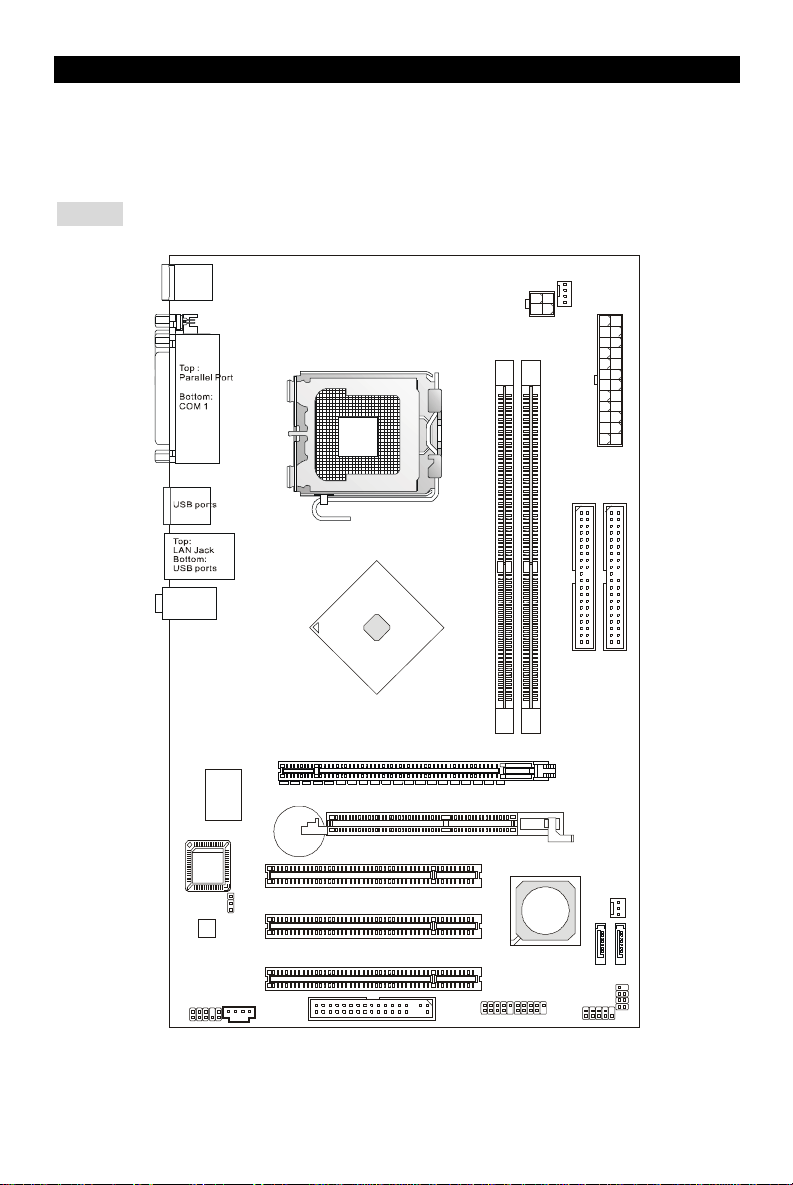
Thank you for choosing the 649 Neo-V (MS-7113 v1.X) Series ATX mainboard. The 649 Neo-V
Series is based on SiS® 649 & SiS® 965L chipsets for optimal system efficiency. Designed to fit
the advanced Intel® P4 Prescott 533/ 800MHz processors in LGA775 package, the 649 Neo-V
Series delivers a high performance and professional desktop platform solution.
Layout
T: mouse
B: keyboard
CPUFAN1
JPW1
IDE2
ATX1
IDE1
T:
Line-In
Line-Out
M:
B:Mic
SiS
649
Chipset
Winbond
W83627THF
PCI_E 1
Codec
JBAT1
+
PCI Slot 1
SYSFAN1
PCI Slot 2
SiS
965L
Chipset
JUSB2
SATA2
JFP1
SATA1
JFP2
JAUD1
CD1
PCI Slot 3
FDD1
JUSB1
1
Page 6

Specifications
CPU
l Supports Intel Pentium 4 / Celeron D Prescott processors in LGA775 package.
l Supports up to Pentium 4 3XX, 5XX and 6XX sequence processor or higher speed.
l Supports Intel Hyper-Threading Technology.
l For the latest information about CPU, please visit
http://www.msi.com.tw/program/products/mainboard/mbd/pro_mbd_cpu_support.php
Chipset
l SiS® 649 chipset
- Supports FSB 533/ 800 MHz.
- Supports PCI Express x 16 interface.
- Supports DDR333/ DDR400 memory interface.
l SiS® 965L chipset
- Hi-Speed USB (USB2.0) controller, 480Mb/sec, 8 ports.
- 2 Serial ATA ports with transfer rate up to 1.5Gb/s
- 2 channel Ultra ATA 66/100/ 133 bus Master IDE controller.
- PCI Master v2.3, I/O APIC.
- Supports both ACPI and legacy APM power management.
Main Memory
l Supports two unbuffered DIMM of DDR SDRAM.
l Supports up to 2GB memory size without ECC.
l Supports DDR333/ DDR400 MHz.
(For the updated supporting memory modules, please visit
http://www.msi.com.tw/program/products/mainboard/mbd/pro_mbd_trp_list.php )
Slots
l One PCI Express x16 slot (supports PCI Express Bus specification v1.0a compliant).
l One AGR (Advance Graphics Riser) slot for compatible AGP VGA cards.
l Three PCI 2.3 32-bit PCI bus slots (support 3.3v/5v PCI bus interface).
On-Board IDE
l One Ultra DMA 66/100/133 IDE controller integrated in 965L.
- Supports PIO, Bus Master operation modes
- Can connect up to four Ultra ATA drives.
l Serial ATA/150 controller integrated in 965L
- Up to 150MB/sec transfer speeds.
- Can connect up to two Serial ATA drives.
2
Page 7

On-Board Peripherals
l On-Board Peripherals includes:
- 1 floppy port supports 1 FDDs with 360K, 720K, 1.2M, 1.44M and 2.88Mbytes.
- 1 serial ports (Rear * 1) and 1 parallel port supports SPP/EPP/ECP mode.
- 8 USB 2.0 ports (Rear * 4/ Front * 4).
- 3 audio (Line-In/Line-Out/Mic) jacks.
- 1 RJ-45 LAN Jack.
Audio
l AC97 link controller integrated in 965L chipset.
l 6-channel audio codec ADI AD1888.
- Compliance with AC97 v2.3 Spec.
- Meet PC2001 audio performance requirement.
LAN
l Broadcom AC131
- Integrated Fast Ethernet PHY.
- Supports 10Mb/s and 100Mb/s.
- Compliance with PCI 2.2.
- Supports ACPI Power Management.
BIOS
l The mainboard BIOS provides “Plug & Play” BIOS which detects the peripheral devices and
expansion cards of the board automatically.
l The mainboard provides a Desktop Management Interface (DMI) function that records your
mainboard specifications.
Dimension
l ATX Form Factor: 30.5 cm x 18.5 cm.
Mounting
l 6 mounting holes.
Others
l Supports PS/2 Keyboard/Mouse
l Hardware monitor is to monitor temperature and voltage.
3
Page 8
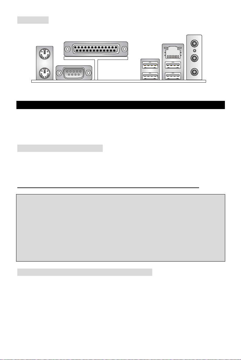
Rear Panel
Parallel port
Line ln
Line Out
MIC
The rear panel provides the following connectors:
Mouse
LAN
USB ports
Keyboard
COM port
USB ports
Hardware Setup
This chapter tells you how to install the CPU, memory modules, and expansion cards, as well as
how to setup the jumpers on the mainboard. It also provides the instructions on connecting the
peripheral devices, such as the mouse, keyboard, etc. While doing the installation, be careful in
holding the components and follow the installation procedures.
Central Processing Unit: CPU
The mainboard supports Intel Pentium 4 / Celeron D Prescott processor. The mainboard uses a
CPU socket called LGA775. When you are installing the CPU, make sure to install the cooler to
prevent overheating. If you do not have the CPU cooler, contact your dealer to purchase and
install them before turning on the computer. For the latest information about CPU, please visit
http://www.msi.com.tw/program/products/mainboard/mbd/pro_mbd_cpu_support.php
MSI Reminds You...
Overheating
Overheating will seriously damage the CPU and system, always make sure the cooling fan can
work properly to protect the CPU from overheating.
Overclocking
This motherboard is designed to support overclocking. However, please make sure your
components are able to tolerate such abnormal setting, while doing overclocking. Any attempt to
operate beyond product specifications is not recommended. We do not guarantee the damages
or risks caused by inadequate operation or beyond product specifications.
LGA775 CPU Installation (CPU Clip is optional)
When you are installing the CPU, make sure the CPU has a cooler attached on the top to prevent
overheating. If you do not have the cooler, contact your dealer to purchase and install them
before turning on the computer. Meanwhile, do not forget to apply some silicon heat transfer
compound on CPU before installing the cooler for better heat dispersion.
Follow the steps below to install the CPU & cooler correctly. Wrong installation will cause the
damage of your CPU & mainboard.
4
Page 9
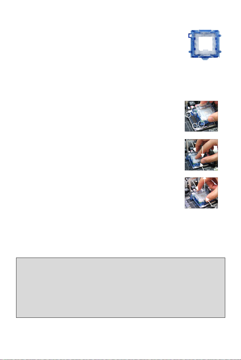
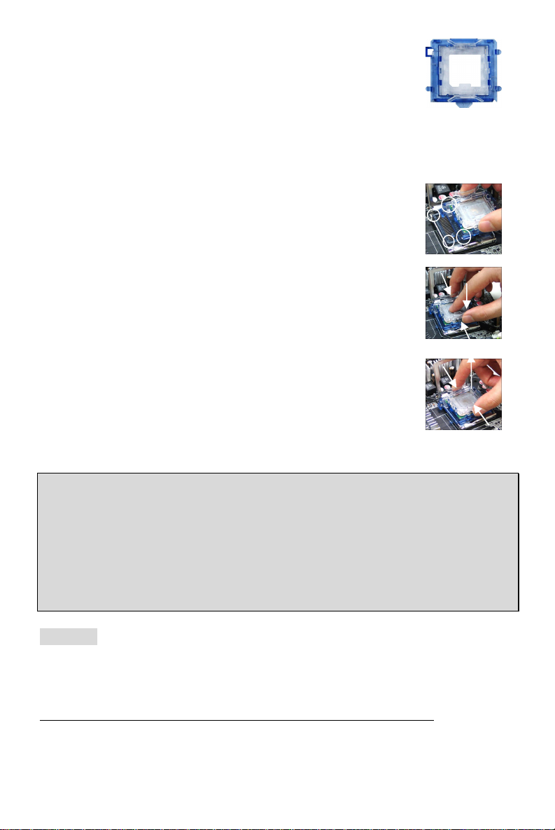
1. The CPU has a land side cover on the bottom to protect the CPU contact from damage.
Rotate it to make the pin 1 indicator (yellow triangle) in the left-bottom
corner. The availability of it depends on the CPU packing.
2. Take out the accompanying CPU Clip (shown in the right) and rotate it
for the same direction as the CPU (Pin 1 indicator is in the left-bottom
corner).
3. Use 2 hands to remove the land side cover (if any). Please note not to touch the pins.
4. Align the two pin 1 indicators (the triangles on the CPU & the CPU Clip), and use the CPU
Clip to clip the CPU up, pressing the clips on both sides to the center, as the arrows
shown.
5. The CPU has a plastic cap on it to protect the contact from damage. Before you have
installed the CPU, always cover it to protect the socket pin.
6. Remove the cap from lever hinge side. The pins of socket reveal.
7. Lift the load lever up and open the load plate.
8. Correctly align the triangle of CPU Clip with the CPU chamfer, and
the square on the CPU Clip to the hook of the socket.
9. Use your thumb and the middle fingers to push the clips to release
the CPU, then press down the CPU with your index finger to allow
the whole module to be installed onto the CPU socket.
10. The CPU is installed well on the CPU socket.
11. Visually inspect if the CPU is seated well into the socket, then
remove the CPU Clip with 2 fingers. Then cover the load plate onto
the package.
12. Press down the load lever lightly onto the load plate, and then secure
the lever with the hook under retention tab.
13. Align the holes on the mainboard with the cooler. Push down the
cooler until its four clips get wedged into the holes of the mainboard.
14. Press the four hooks down to fasten the cooler. Then rotate the locking switch (refer to the
correct direction marked on it) to lock the hooks.
15. Turn over the mainboard to confirm that the clip-ends are correctly inserted.
Note: If you want to uninstall the CPU, align the 4 points (see Point 8 for details) again and push
the clip to lift up the CPU.
MSI Reminds You...
1. Confirm if your CPU cooler is firmly installed before turning on your system.
2. Check the information in H/W Monitor in BIOS for the CPU temperature.
3. Do not touch the CPU socket pins to avoid damaging.
4. Whenever CPU is not installed, always protect your CPU socket pin with the plastic cap
covered to avoid damaging.
5. Please note that the mating/unmating durability of the CPU is 20 cycles. Therefore we suggest
you do not plug/unplug the CPU too often.
5
Page 10
Memory
Notch
Volt
1
3
4
2
GND
GND
1
12
24
13
+3.3V
+3.3V
PS-ON#
PWR OK
The mainboard provides two 184-pin unbuffered DDR333 / DDR400 DDR SDRAM, and supports
the memory size up to 2GB. To operate properly, at least one DIMM module must be installed.
(For the updated supporting memory modules, please visit
http://www.msi.com.tw/program/products/mainboard/mbd/pro_mbd_trp_list.php)
Install at least one DIMM module on the slots. Memory modules can be installed on the slots in
any order. You can install either single- or double-sided modules to meet your own needs.
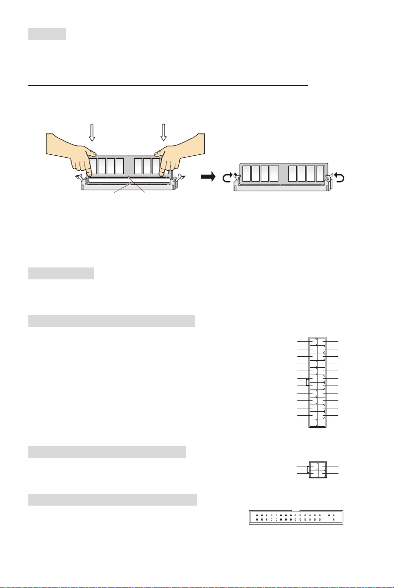
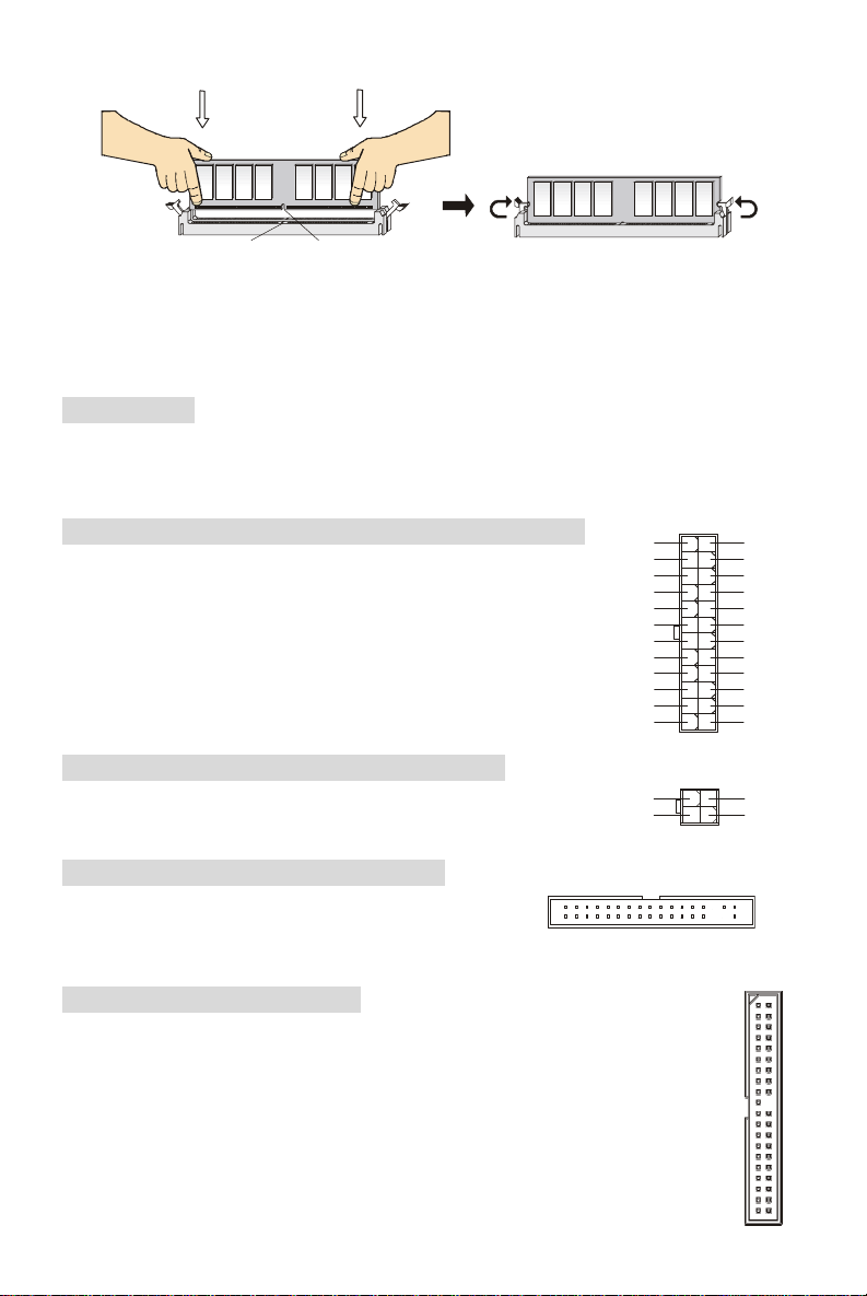
Installing DDR Modules
1. The DDR DIMM has only one notch on the center of module. The module will only fit in the
right orientation.
2. Insert the DIMM memory module vertically into the DIMM slot. Then push it in until the
golden finger on the memory module is deeply inserted in the socket.
3. The plastic clip at each side of the DIMM slot will automatically close.
Power Supply
The mainboard supports ATX power supply for the power system. Before inserting the power
supply connector, always make sure that all components are installed properly to ensure that no
damage will be caused. A 300W or above power supply is suggested.
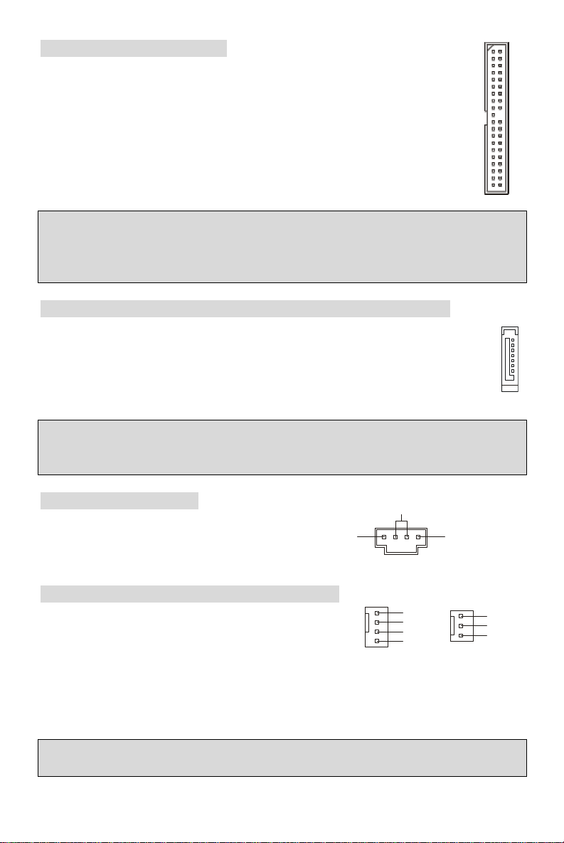
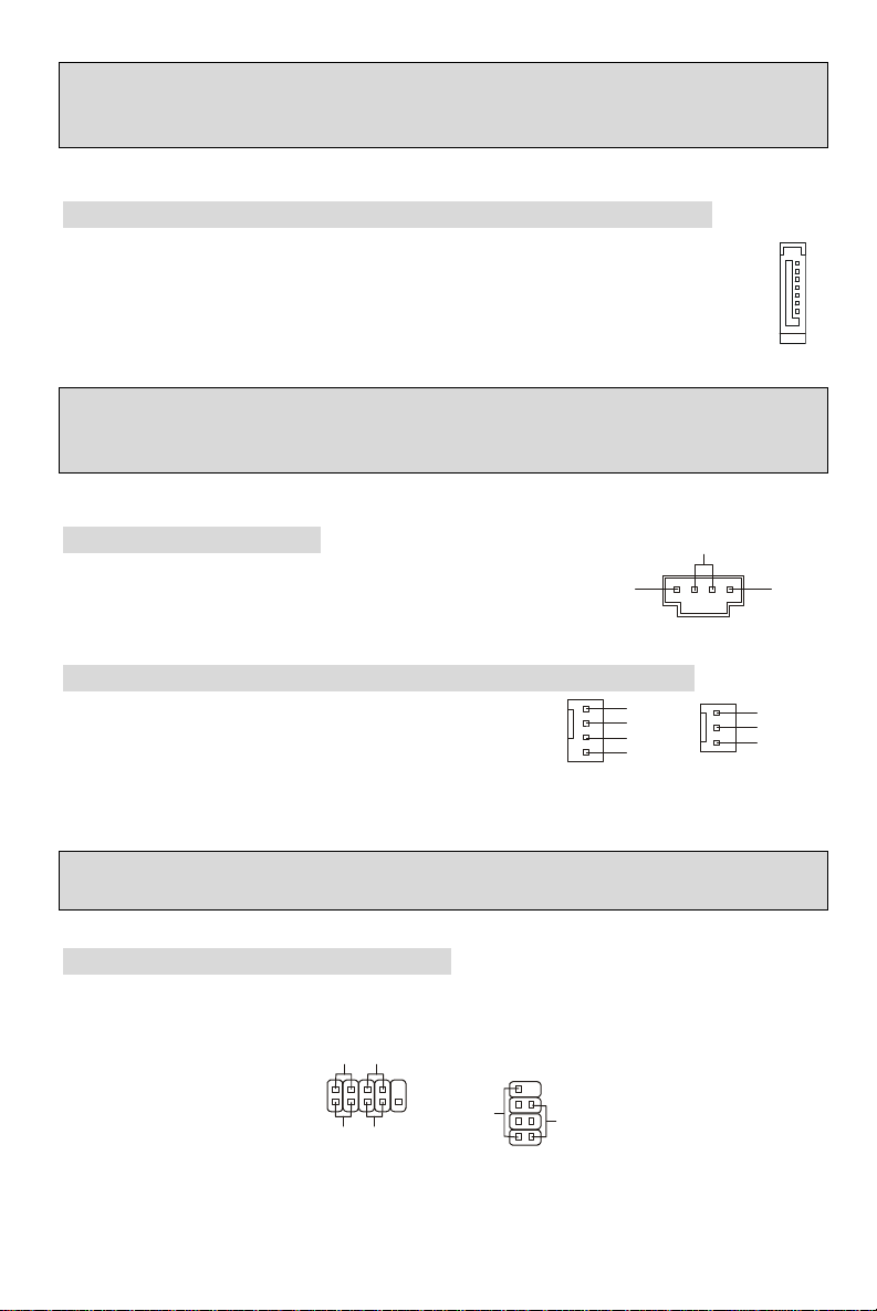
ATX 24-Pin Power Connector: ATX1
This connector allows you to connect an ATX 24-pin power supply. To
connect the ATX 24-pin power supply, make sure the plug of the
power supply is inserted in the proper orientation and the pins are
aligned. Then push down the power supply firmly into the connector.
You may use the 20-pin ATX power supply power supply as you like.
If you’d like to use the 20-pin ATX power supply, please plug your
power supply along with pin 1 & pin 13 (refer to the image at the right
hand). There is also a foolproof design on pin 11, 12, 23 & 24 to
avoid wrong installation.
+3.3V
-12V
GND GND
GND GND
GND +5V
GND GND
Res
+5V 5VSB
+5V +12V
+5V +12V
GND NC
+5V
ATX 12V Power Connector: JPW1
This 12V power connector is used to provide power to the CPU.
12V
12V
Floppy Disk Drive Connector: FDD1
The mainboard provides a standard floppy disk drive
connector that supports 360K, 720K, 1.2M, 1.44M and
2.88M floppy disk types.
6
Page 11
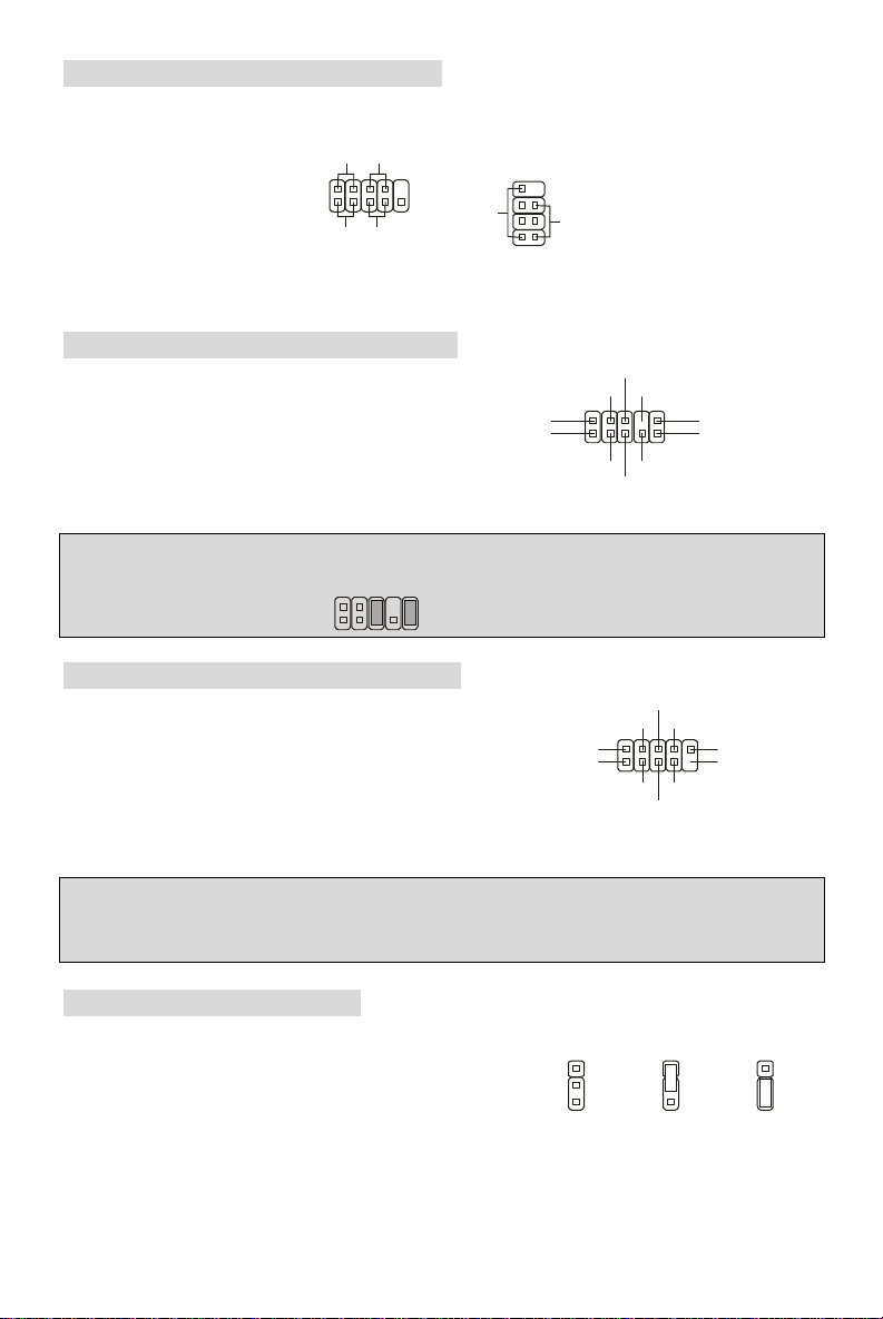
IDE Connectors: IDE1/ IDE2
GND
+12V
1
R
GND
Sensor
Control
The mainboard has a 32-bit Enhanced PCI IDE and Ultra DMA 66/100/133 controller
that provides PIO mode 0~4, Bus Master, and Ultra DMA 66/100/133 function. You
can connect up to four IDE interface devices as Hard Disk, CD-ROM, 120MB Floppy,
etc.
The first hard drive should always be connected to IDE1. IDE1 can connect a Master
and a Slave drive. You must configure second hard drive to Slave mode by setting the
jumper accordingly.
MSI Reminds You...
If you install two hard disks on cable, you must configure the second drive to Slave mode by
setting its jumper. Refer to the hard disk documentation supplied by hard disk vendors for jumper
setting instructions.
Serial ATA Connectors controlled by SiS 965L: SATA1/SATA2
The Southbridge of this mainboard is SiS 965L, which supports two serial connectors
SATA1~2.
SATA1~2 are dual high-speed Serial ATA interface ports. Each supports 1st generation
serial ATA data rates of 150 MB/s. All SATA connectors are fully compliant with Serial
ATA 1.0 specifications. Each Serial ATA connector can connect to 1 hard disk device.
MSI Reminds You...
Please do not fold the serial ATA cable in a 90-degree angle, which will cause the loss of data
during transmission.
7
CD-In Connector: JCD1
The connector is for CD-ROM audio connector.
L
Fan Power Connectors: CPUFAN1/SYSFAN1
The 4-pin CPUFAN1 (processor fan) and 3-pin SYSFAN1
(system fan) support system cooling fan with +12V. CPUFAN1
can support three- or four-pin head connector. When
connecting the wire to the connectors, always take note that the red wire is the positive and
should be connected to the +12V, the black wire is Ground and should be connected to GND. If
the mainboard has a System Hardware Monitor chipset on-board, you must use a specially
designed fan with speed sensor to take advantage of the CPU fan control.
MSI Reminds You...
Always consult the vendors for proper CPU cooling fan.
7
GND
+12V
NC
Page 12
Front Panel Connectors: JFP1/JFP2
9210
USB0+
USB1+
USB0C(10)
1
133
322
2
Keep Data
Clear Data
JFP1
Power
Switch
Power
Switch
10
JFP2
Power
8
AUD_RET_R
AUD_RET_L(10)
AUD_FPOUT_L(9)
The mainboard provides two front panel connectors for electrical connection to the front panel
switches and LEDs. JFP1 is compliant with Intel Front Panel I/O Connectivity Design Guide.
LED
2
1 9
HDD
Reset
LED
Speaker
LED
172
Front Panel Audio Connector: JAUD1
The front panel audio connector allows you to
connect to the front panel audio and is
compliant with Intel® Front Panel I/O
Connectivity Design Guide.
(2)AUD_GND
(1)AUD_MIC
AUD_MIC_BIAS
AUD_VCC
Key
HP_ON
AUD_FPOUT_R
MSI Reminds You...
If you do not want to connect to the front audio header, pins 5 & 6, 9 & 10 have to be jumpered in
order to have signal output directed to the rear audio ports. Otherwise, the Line-Out connector on
the back panel will not function.
Front USB Connector: JUSB1/ JUSB2
The mainboard provides two standard USB 2.0 pin
headers JUSB1 & JUSB2. USB2.0 technology increases
data transfer rate up to a maximum throughput of 480Mbps,
which is 40 times faster than USB 1.1, and is ideal for
connecting high-speed USB interface peripherals such as
USB HDD, digital cameras, MP3 players, printers, modems and the like.
MSI Reminds You...
Please note that the pins of VCC & GND must be connected correctly, or it may cause some
damage.
Clear CMOS Jumper: JBAT1
There is a CMOS RAM on board that has a power supply from external battery to keep the data
of system configuration. With the CMOS RAM, the system
can automatically boot OS every time it is turned on. If you
want to clear the system configuration, use the JBAT1
(Clear CMOS Jumper) to clear data. Follow the instructions
in the image to clear the data.
1
USB1- GND
(2)VCC
(1)VCC Key(9)
GND
USB0-
1
8
Page 13

MSI Reminds You...
You can clear CMOS by shorting 2-3 pin while the system is off. Then return to 1-2 pin position.
Avoid clearing the CMOS while the system is on; it will damage the mainboard.
PCI Express x16 Slot
The PCI Express x16 slot, as a high-bandwidth, low pin count, serial, interconnect technology,
support Intel highest performance desktop platforms utilizing the Intel Pentium 4 processor with
HT Technology.
PCI Express architecture provides a high performance I/O infrastructure for Desktop Platforms
with transfer rates starting at 2.5 Giga transfers per second over a PCI Express x1 lane for
Gigabit Ethernet, TV Tuners, 1394 controllers, and general purpose I/O. Also, desktop platforms
with PCI Express Architecture will be designed to deliver highest performance in video, graphics,
multimedia and other sophisticated applications. Moreover, PCI Express architecture provides a
high performance graphics infrastructure for Desktop Platforms doubling the capability of existing
AGP8x designs with transfer rates of 4.0 GB/s over a PCI Express x16 lane for graphics
controllers, while PCI Express x1 supports transfer rate of 250 MB/s.
You can insert the expansion cards to meet your needs. When adding or removing expansion
cards, make sure that you unplug the power supply first.
PCI (Peripheral Component Interconnect) Slots
The PCI slots allow you to insert the expansion cards to meet your needs. When adding or
removing expansion cards, make sure that you unplug the power supply first. Meanwhile, read
the documentation for the expansion card to make
any necessary hardware or software settings for the
expansion card, such as jumpers, switches or BIOS
configuration.
PCI Interrupt Request Routing
The IRQ, abbreviation of interrupt request line and pronounced I-R-Q, are hardware lines over
which devices can send interrupt signals to the microprocessor. The PCI IRQ pins are typically
connected to the PCI bus INT A# ~ INT D# pins as follows:
Order1 Order2 Order3 Order4
PCI Slot 1 INT B# INT C# INT D# INT A#
PCI Slot 2 INT C# INT D# INT A# INT B#
PCI Slot 3 INT D# INT A# INT B# INT C#
AGR (Advance Graphics Riser) Slot
The AGR (Advance Graphics Riser) slot is a
special design that only supports compatible
AGP VGA cards.
9
Page 14
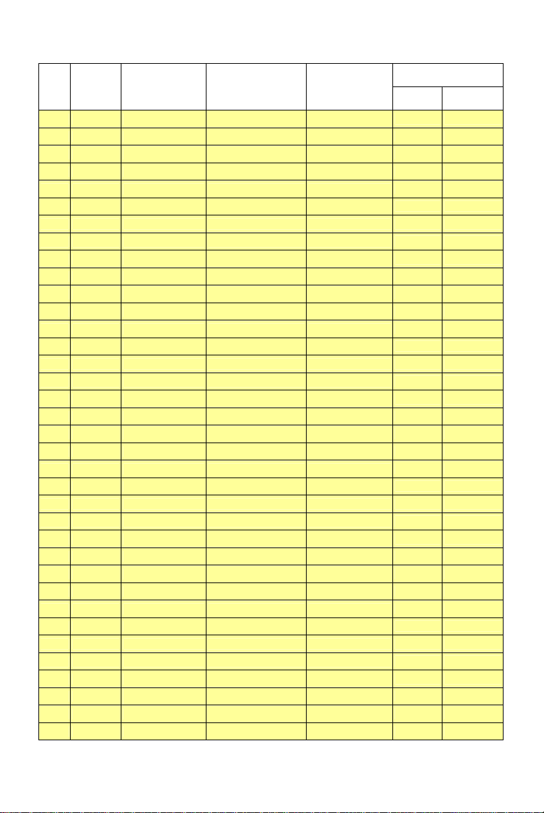
Compatible VGA Card List
VGA CARD
No.
Vender
1 Alvatron FX5700U GeForce FX5700 Ultra 128MB/DDR SDRAM
2 ATI Fire GL 8800 Fire GL 8800 128MB/SDRAM
3 ATI Radeon 9800 XT Radeon 9800 XT 256MB/DDR SDRAM
4 GAINWARD GFX 5900 Ultra GeForce 4 FX 5900 U 256MB/DDR SDRAM
5 Gigabyte GV-R9200 Radeon 9200 128MB/DDR SDRAM
6 Gigabyte GV-N57L128D GeForce FX5700LE 128MB/DDR SDRAM
7 Leadtek Winfast A360LE TD GeForce FX5700LE 128MB/DDR SDRAM
8 Leadtek Winfast A400GT TDH GeForce 6800GT 256MB/DDR SDRAM
9 MSI MS-8863 GeForce 4 MX 460 64MB/SDRAM
10 MSI MS-8907 GeForce FX 5200 64MB/DDR SDRAM
11 MSI MS-8911 GeForce FX 5200 128MB/DDR SDRAM
12 MSI MS-8919 GeForce FX 5200 128MB/DDR SDRAM
13 MSI MS-8923 GeForce FX 5200 Ultra 128MB/DDR SDRAM
14 MSI MS-8929 GeForce FX 5900 128MB/DDR SDRAM
15 MSI MS-8931 GeForce FX 5600 Ultra 128MB/DDR SDRAM
16 MSI MS-8936 GeForce4 MX4000 64MB/DDR SDRAM
17 MSI MS-8936 GeForce FX5500 128MB/DDR SDRAM
18 MSI MS-8946 GeForce FX 5950 Ultra 256MB/DDR SDRAM
19 MSI MS-8959 GeForce FX5700LE 128MB/DDR SDRAM
20 MSI MS-8975 Nvidia GeForce 6800 128MB/DDR SDRAM
21 Unika FX5200 SP5208 GeForce FX5200 64MB/DDR SDRAM
22 MSI MS-8952 ATI Radeon 9250 128MB/DDR SDRAM
23 Power Color R92U-LC3 Radeon 9250 128MB/DDR SDRAM
24 Power Color RV6DE-NB3 Radeon 7000 64MB/DDR SDRAM
25 ATI Radeon LE Radeon LE DDR 32MB/DDR SGRAM
26 ATI Radeon 7500 LE Radeon DDR 64MB/SDRAM
27 ATI Fire GL 8700 Fire GL 8700 64MB/DDR SDRAM
28 ATI Radeon 9000 Pro Radeon DDR 64MB/DDR SDRAM
29 ATI Radeon 9500 Radeon 9500 64MB/DDR SDRAM
30 ATI Radeon 9700 Radeon 9700 128MB/DDR SDRAM
31 ASUS AGP-V7700 Deluxe GeForce 2 GTS 32MB/DDR SGRAM
32 ASUS V8440 GeForce 4 Ti 4400 128MB/SDRAM
33 ASUS V8460 Ultra GeForce 4 Ti 4600 128MB/SDRAM
34 Creative
35 ELSA Gladiac 517 SV GeForce 4 MX420 64MB/SDRAM
36 ELSA Gladiac 528 Ultra GeForce 4 Ti 4200 128MB/DDR SDRAM
Model name VGA Chip VGA Memory
3D Blaster 5 RX9700
Radeon 9700 128MB/SGRAM
MS-7113
Result Driver Ver.
Pass 6.14.10.7125
Pass 6.12.10.3056
Pass 6.14.10.6476
Pass 6.14.10.7125
Pass 6.14.10.6512
Pass 6.14.10.7125
Pass 6.14.10.7125
Pass 6.14.10.7125
Pass 6.14.10.2958
Pass 6.14.10.7125
Pass 6.14.10.7125
Pass 6.14.10.7125
Pass 6.14.10.7125
Pass 6.14.10.7125
Pass 6.14.10.7125
Pass 6.14.10.6681
Pass 6.14.10.7125
Pass 6.14.10.7125
Pass 6.14.10.7125
Pass 6.14.10.7125
Pass 6.14.10.7125
Pass 6.14.10.6512
Pass 6.14.10.6505
Pass 6.13.10.6476
Pass 6.13.10.6153
Pass 6.13.10.6153
Pass 6.12.10.3051
Pass 6.14.10.6458
Pass 6.14.10.6458
Pass 6.14.10.6458
Pass 6.14.10.2958
Pass 6.14.10.2958
Pass 6.14.10.2958
Pass 6.14.10.6458
Pass 6.14.10.2958
Pass 6.14.10.6681
10
Page 15

37 GAINWARD GeForce 4 MX460 64MB/DDR
38 GAINWARD GeForce 4 MX440T 64MB/SDRAM
39 GAINWARD GeForce 4 MX440 64MB/DDR SDRAM
40 Leadtek Winfast GeForce3 Titanium 500 TD 64MB/SDRAM
41 Leadtek Winfast A170 TH GeForce 4 MX 420 64MB/SDRAM
42 Leadtek Winfast A250 TD GeForce 4 4400 Ti 128MB/SDRAM
43 MSI MS-8806 Nvidia RIVA TNT2 32MB/SDRAM
44 MSI MS-8831 GeForce GTS Pro 64MB/SDRAM
45 MSI MS-8847 GeForce 4 MX 440 64MB/DDR SDRAM
46 MSI MS-8851 GeForce 3 Ti 200 64MB/SDRAM
47 MSI MS-8852 GeForce 2 MX 100/200 32MB/SDRAM
48 MSI MS-8860 GeForce 4 MX 440 64MB/SDRAM
49 MSI MS-8861 GeForce 4 MX 440 64MB/SDRAM
50 MSI MS-8870 GForce 4 Ti 4200 64MB/DDR SDRAM
51 MSI MS-8872 GeForce 4 Ti 4600 128MB/DDR SDRAM
52 MSI MS-8879 GeForce 4 Ti 4200 64MB/DDR SDRAM
53 MSI MS-8883 GeForce 4 MX 460 128MB/DDR SDRAM
54 MSI MS-8888 GeForce 4 MX 440 64MB/DDR SDRAM
55 MSI MS-8889 GeForce 4 Ti 4200 128MB/DDR SDRAM
56 MSI MS-8890 GeForce 4 MX 440 64MB/DDR SDRAM
57 MSI MS-8891 GeForce 4 MX 440 128MB/DDR SDRAM
58 MSI MS-8894 GeForce 4 Ti 4200 128MB/DDR SDRAM
59 MSI MS-8895 GeForce 4 MX 440 64MB/DDR SDRAM
60 MSI MS-8900 GeForce 4 Ti 4800 SE 128MB/DDR SDRAM
61 MSI MS-8904 GeForce FX 5800 128MB/DDR SDRAM
62 MSI MS-8948 GeForce FX 5700 128MB/DDR SDRAM
63 NS GF4 MX440 GeForce 4 MX 440 64MB/DDR SDRAM
64 Pixel View MVGA-NBG25GA GeForce 4 Ti 4200 128MB/SDRAM
65 Triplex Xabre Pro 64MB/SDRAM
66 Triplex Millennium Silver GeForce 4 MX 440 64MB/DDR
67 Triplex SIS Sabre 600 Ultra 64MB/DDR SDRAM
68 VINIX VINIX VX-3340 XABRE400 64MB/DDR SDRAM
69 MSI MS-8988 GeForce 6600 256MB/DDR SDRAM
Pass 6.14.10.5673
Pass 6.14.10.2958
Pass 6.14.10.6681
Pass 6.14.10.2958
Pass 6.14.10.2958
Pass 6.14.10.2958
Pass 6.14.10.6681
Pass 6.14.10.2958
Pass 6.14.10.5673
Pass 6.14.10.6681
Pass 6.14.10.6681
Pass 6.14.10.2958
Pass 6.14.10.2958
Pass 6.14.10.2958
Pass 6.14.10.2958
Pass 6.14.10.2958
Pass 6.14.10.2958
Pass 6.14.10.5673
Pass 6.14.10.6681
Pass 6.14.10.5673
Pass 6.14.10.6681
Pass 6.14.10.6681
Pass 6.14.10.6681
Pass 6.14.10.6681
Pass 6.14.10.5673
Pass 6.14.10.6681
Pass 6.14.10.2958
Pass 6.14.10.2958
Pass 6.13.10.3080
Pass 6.14.10.2958
Pass 6.13.10.3080
Pass 6.13.10.3080
Pass 7.1.2.5
Please visit http://www.msi.com.tw/program/products/mainboard/mbd_index.php for updated
information.
11
Page 16
BIOS Setup
Power on the computer and the system will start POST (Power On Self Test) process. When the
message below appears on the screen, press <DEL> key to enter Setup.
DEL: Setup F11: Boot Menu
If the message disappears before you respond and you still wish to enter Setup, restart the
system by turning it OFF and On or pressing the RESET button. You may also restart the system
by simultaneously pressing <Ctrl>, <Alt>, and <Delete> keys.
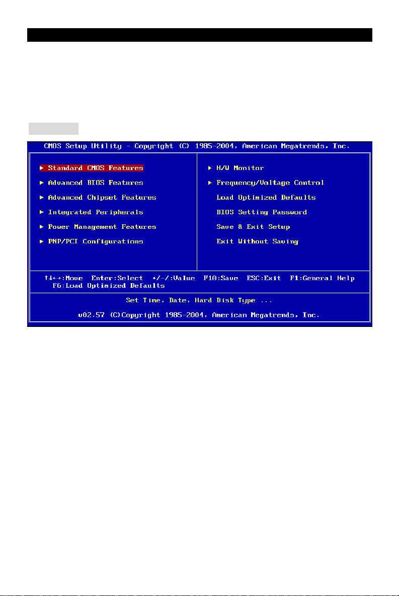
Main Page
Standard CMOS Features
Use this menu for basic system configurations, such as time, date etc.
Advanced BIOS Features
Use this menu to setup the items of AMI special enhanced features.
Advanced Chipset Features
Use this menu to change the values in the chipset registers and optimize your system
performance.
Integrated Peripherals
Use this menu to specify your settings for integrated peripherals.
Power Management Setup
Use this menu to specify your settings for power management.
PNP/PCI Configurations
This entry appears if your system supports PnP/PCI.
H/W Monitor
This entry shows your PC health status.
12
Page 17
Frequency/Voltage Control
Use this menu to specify your settings for frequency/voltage control.
Load Optimized Defaults
Use this menu to load factory optimized default settings into the BIOS for stable system
performance operations.
BIOS Setting Password
Use this menu to set Password.
Save & Exit Setup
Save changes to CMOS and exit setup.
Exit Without Saving
Abandon all changes and exit setup.
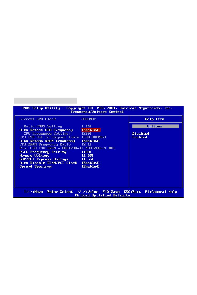
Frequency/Voltage Control
Auto Detect CPU Frequency
This item can auto detect the CPU frequency. When you set this item to “Disabled”, the following
item “CPU Frequency Setting” will be selectable.
CPU Frequency Setting
This item allows you to select the CPU Front Side Bus clock frequency and overclock the
processor by adjusting the FSB clock to a higher frequency. Select the number between
[100]~[355] for needed frequency. The default settings are: [133], [200].
Auto Detect DRAM Frequency
This item can auto detect the DRAM frequency. When you set this item to “Disabled”, the
following item “CPU:DRAM Frequency Ratio” will be selectable.
13
Page 18

CPU:DRAM Frequency Ratio
This item allows you to select the CPU:DRAM frequency ratio. The setting options depend on
CPU and DRAM frequencies.
Spread Spectrum
When the motherboard’s clock generator pulses, the extreme values (spikes) of the pulses
creates EMI (Electromagnetic Interference). The Spread Spectrum function reduces the EMI
generated by modulating the pulses so that the spikes of the pulses are reduced to flatter curves.
If you do not have any EMI problem, leave the setting at [Disabled] for optimal system stability
and performance. But if you are plagued by EMI, set to [Enabled] for EMI reduction. Remember
to disable Spread Spectrum if you are overclocking because even a slight jitter can introduce a
temporary boost in clock speed which may just cause your overclocked processor to lock up.
Load Optimized Defaults
You can load the BIOS Setup default values provided by the mainboard manufacturer for the
stable performance.
For the complete BIOS introduction and setup, please visit MSI website at
http://www.msi.com.tw
14
Page 19

Introduction
BIOS
DIMM1DIMM
2
BATT
AGR Slot
Félicitations, vous venez d’acquérir une carte mère ATX 649 Neo-V (MS-7113 v1.X) Series. Les
649 Neo-V Series sont basées sur les chipsets SiS® 649 & SiS® 965L offrant un système très
performant. La carte fonctionne avec les processeurs Intel® P4 Prescott 533/ 800MHz (LGA775),
les 649 Neo-V Series est très performante et offre une solution adaptée tant aux professionnels
qu’aux particuliers.
Schéma
T: mouse
B: keyboard
CPUFAN1
JPW1
IDE2
ATX1
IDE1
T:
Line-In
Line-Out
M:
B:Mic
SiS
649
Chipset
Winbond
W83627THF
PCI_E 1
Codec
JBAT1
+
PCI Slot 1
SYSFAN1
PCI Slot 2
SiS
965L
Chipset
JUSB2
SATA2
JFP1
SATA1
JFP2
JAUD1
CD1
PCI Slot 3
FDD1
JUSB1
15
Page 20

Spécificités
CPU
l Supporte les processeurs Intel Pentium 4 / Celeron D Prescott LGA775 pour LGA775
l Supporte jusqu’à Pentium 4 3XX, 5XX et 6XX ou plus.
l Supporte la technologie Intel Hyper-Threading.
(Pour les dernières mises à jours concernant les CPU, vous pouvez visiter :
http://www.msi.com.tw/program/products/mainboard/mbd/pro_mbd_cpu_support.php.)
Chipset
l Chipset SiS® 649
- Supporte FSB 533/ 800 MHz.
- Supporte l’interface PCI Express x 16.
- Supporte la mémoire d’interface DDR333/ DDR400.
l Chipset SiS® 965L
- Contrôleur Hi-Speed USB (USB2.0), 480Mb/sec, 8 ports.
- 2 ports Serial ATA avec taux de transfert jusqu’à 1.5Gb/s
- 2 contrôleurs IDE Bus Master channel Ultra ATA 66/100.
- PCI Master v2.3, I/O APIC.
- Supporte à la fois l’ACPI et la gestion de l’alimentation (APM).
Mémoire Principale
l Supporte deux DIMM unbuffered DDR SDRAM
l Supporte jusqu’à 2GB de mémoire non ECC.
l Supporte DDR333/ DDR400 MHz.
(Pour connaître les derniers modules de mémoire supportés, vous pouvez visiter :
http://www.msi.com.tw/program/products/mainboard/mbd/pro_mbd_trp_list.php)
Slots
l Un slot PCI Express x16 (Compatible avec les spécificités Bus PCI Express v1.0a).
l Un slot AGR (Advance Graphics Riser) compatible avec les cartes VGA AGP.
l Trois slots Bus PCI 2.3 32-bit (supporte l’interface bus PCI 3.3v/5v).
IDE Intégré
l Un contrôleur Ultra DMA 66/100/133 IDE intégré dans 965L.
- Supporte les modes opératoires PIO, Bus Master
- Possibilité de connecter jusqu’à quatre disques Ultra ATA.
l Contrôleur Serial ATA/150 intégré dans 965L
- Vitesse de transfert jusqu’à 150MB/sec.
- Possibilité de connecter jusqu’à deux disques Serial ATA.
16
Page 21

Périphériques Intégrés
l Périphériques Intégrés Inclus:
- 1 port floppy supportant 1 FDDs avec 360K, 720K, 1.2M, 1.44M et 2.88Mbytes.
- 1 ports de série (Arrière * 1) et 1 port parallèle supportant les modes SPP/EPP/ECP.
- 8 ports USB 2.0 (Arrière * 4/ Avant * 4).
- 3 ports audio (Line-In/Line-Out/Mic).
- 1 RJ-45 LAN Jack.
Audio
l Contrôleur AC97 link intégré dans chipset 965L.
l 6 canaux audio codec ADI AD1888.
- Compatible avec les spec AC97 v2.3.
- Réponds aux exigences audio PC2001.
LAN
l Broadcom AC131
- Fast Ethernet PHY intégré.
- Supporte 10Mb/s et 100Mb/s.
- Compatible avec PCI 2.2.
- Supporte l’ACPI Power Management.
BIOS
l La carte procure un BIOS “Plug & Play” qui détecte automatiquement les cartes d’extension
ou les périphériques.
l La carte offre une interface DMI (Desktop Management Interface) qui enregistre les
spécificités de la carte mère.
Dimension
l Format ATX: 30.5 cm x 18.5 cm.
Montage
l 6 trous de montage.
Autres
l Supporte Clavier/Souris PS/2.
l Le « Hardware monitor » permet de surveiller la temperature & voltage.
17
Page 22

Panneau Arrière
Parallel port
Line ln
Line Out
MIC
Le panneau arrière procure les connecteurs suivants:
Mouse
LAN
USB ports
Keyboard
COM port
USB ports
Installation Matériel
Ce chapitre vous indique comment installer le processeur, barrettes de mémoire et cartes
d’extension. Lors de l’installation des matériels, veuillez suivre les instructions de montage pour
éviter d’endommager quoi que ce soit.
Central Processing Unit: CPU
La carte supporte les processeurs Intel Pentium 4 / Celeron D Prescott. Elle utilise le socket CPU
LGA775. , Assurez-vous que vous possédez bien un ventilateur + dissipateur pour éviter la
surchauffe. Si vous ne savez pas quel ventilateur utiliser, veuillez contacter votre revendeur
avant de mettre en marche votre PC. (Pour une mise à jour sur les CPU, veuillez visiter
http://www.msi.com.tw/program/products/mainboard/mbd/pro_mbd_cpu_support.php)
MSI Vous Rappelle...
Surchauffe
Une surchauffe endommagera sérieusement le CPU et le système. Soyez toujours sur du bon
fonctionnement des ventilateurs et radiateurs pour protéger le CPU d’une surchauffe.
Overclocking
Cette carte mère a été cr éée pour supporter l’overclocking. Assurez vous que vos composants
sont capables de tolérer de tels réglages, avant d’overclocker le système. Tout essais au delà
des spécifications des produits n’est pas recommandé. Nous ne garantissons pas les
dommages causés par une mauvaise opération ou au delà des spécifications du produit.
CPU LGA775 et installation Ventilateur (Le Clip CPU est optionnel)
Quand vous installerez votre CPU, assurez vous que le CPU possède un système de
refroidissement pour prévenir les surchauffes. Si vous ne possédez pas de système de
refroidissement, contactez votre revendeur pour vous en procurer un et installez le avant
d’allumer l’ordinateur.
1. Le CPU possède un capuchon de protection pour éviter de l’endommager (à enlever avant
installation). Effectuer une rotation du CPU pour aligner la broche n°1 (triangle jaune) avec
le coin en bas à gauche du socket.
18
Page 23
2. Prendre le CPU Clip bleu de MSI et le faire tourner afin qu’il s’aligne
avec le socket.
3. Il faut ensuite retirer la protection qui se trouve sur le socket de la carte
mère. Veuillez ne pas toucher aux broches du socket.
4. Aligner les indicateurs de couleur jaune (triangle sur le CPU & sur le
clip), et utiliser le clip MSI pour fixer le processeur sur le socket en pratiquant de la façon
indiquée sur la photo.
5. Le CPU possède un capot plastique le protégeant. Ne jamais retirer le capot avant que le
CPU ne soit installé.
6. Retirer la protection socket. Les broches du socket sont visibles.
7. Tirer le levier et ouvrir le plateau.
8. Aligner correctement les marques (clip + CPU).
9. Utilisez vos doigts pour assurer la connexion du CPU sur le socket.
10. Le CPU est bien installé sur le socket.
11. Regarder si le CPU est bien positionné dans le socket. Sinon, retirez
le CPU et installez le de nouveau. Refermer le plateau.
12. Abaisser le levier, puis le sécuriser en l’attachant au mécanisme de
rétention.
13. Aligner les trous de la carte mère avec le ventilateur. Appuyer sur le
ventilateur jusqu’à ce que les clips soient dans les trous de la carte.
14. Appuyer sur les 4 parties (comme indiqué) puis effectuer une rotation
(se référer aux marques) pour sécuriser.
15. Retourner la carte mère pour s’assurer que les clips sont bien insérés.
A Noter: Si vous désirez retirer le processeur, aligner les 4 points comme indiqué précédemment,
et utiliser le clip pour retirer le CPU.
MSI Vous Rappelle...
1. Vérifier la connexion du ventilateur de CPU avant de démarre le PC.
2. Vérifier les informations dans le BIOS H/W Monitor au sujet de la température du CPU.
3. Ne pas toucher les broches du CPU pour éviter de les endommager.
4. Le CPU possède un capot plastique le protégeant. Ne jamais retirer le capot avant que le CPU
ne soit installé pour éviter les dommages.
5. Attention, vous ne pouvez installer/retirer le CPU qu’un nombre de fois limitée à environ 20
cycles, par conséquent veuillez ne pas effectuer cette opération trop souvent.
Mémoire
La carte mère possède deux slots (184 broches) pour modules de mémoire DDR333 / DDR400
DDR SDRAM, et supporte un maximum de mémoire jusqu’à 2GB. Pour fonctionner
correctement, il faut au moins installer un module de mémoire DIMM. (Pour les dernières mises
à jours de mémoire supportées, merci de visiter
http://www.msi.com.tw/program/products/mainboard/mbd/pro_mbd_trp_list.php)
Installer au moins un module DIMM sur les slots. L’installation des modules de mémoires n ’a pas
de sens particulier. Vous pouvez installer soit des modules simples ou doubles faces selon vos
besoins.
19
Page 24
Notch
Volt
1
3
4
2
GND
GND
1
12
24
13
+3.3V
+3.3V
PS-ON#
PWR OK
1. Le DDR DIMM ne possède qu’une encoche en son centre. Ainsi il n’est possible de monter
le module que dans un seul sens.
2. Insérez le module de mémoire DIMM verticalement dans le slot. Puis appuyez dessus
3. Le clip en plastique situé de chaque côté du module va se fermer automatiquement.
Alimentation
La carte mère supporte les alimentations ATX. Avant de brancher le connecteur d’alimentation,
Il faut toujours vous assurer que tous les composants sont bien installés afin de ne pas les
endommager. Une alimentation 300W ou supérieur est préconisée.
Connecteur d’Alimentation ATX 24 Broches : ATX1
Ce connecteur vous permet de connecter l’alimentation ATX. Pour ce
faire assurez-vous que le connecteur est bien positionné dans le bon
sens. Puis appuyer sur le câble.
Vous pouvez aussi utiliser une alimentation 20 broches, le
détrompeur permettra de ne pas connecter l’alimentation sur les
broches 11, 12, 23 & 24.
+3.3V
-12V
GND GND
GND GND
GND +5V
GND GND
Res
+5V 5VSB
+5V +12V
+5V +12V
GND NC
+5V
Connecteur d’Alimentation ATX 12V: JPW1
Le connecteur d’alimentation 12V est utilisé pour alimenter le CPU
12V
12V
Connecteur Floppy Disk Drive: FDD1
La carte offre un connecteur standard floppy disk drive
(lecteur de disquette) qui supporte les disques 360K, 720K,
1.2M, 1.44M et 2.88M.
Connecteurs IDE: IDE1/ IDE2
La carte mère possède un contrôleur 32-bit Enhanced PCI IDE et Ultra DMA
66/100/133 qui procure les fonctions PIO mode 0~4, Bus Master, et Ultra DMA
33/66/100/133. Vous pouvez connecter jusqu’à 4 matériels (disques durs, CD-ROM,
120MB Floppy).
Le premier disque dur doit être connecté sur l’IDE1. L’IDE1 peut recevoir un matériel
Maître et un Esclave. Vous devez configurer le second disque en mode Esclave et ce
à l’aide du cavalier situé à l’arrière
20
Page 25
MSI Vous Rappelle...
GND
+12V
1
R
GND
Sensor
Control
JFP1
Power
Switch
Power
Switch
10
JFP2
Power
8
Si vous voulez installer deux disques durs, vous devez configurer le second en Esclave en
configurant le cavalier. Se référer à la documentation du disque dur pour les instructions.
Connecteurs Serial ATA contrôlés par SiS 965L: SATA1/SATA2
Le Southbridge de cette carte est SiS 965L, qui supporte quatre connecteurs SATA1~2.
SATA1~2 sont deux ports d’interface dual high-speed Serial ATA. Chacun supporte la
1e génération de serial ATA (taux de transfert 150 MB/s). Ces quatre connecteurs sont
entièrement compatibles avec le Serial ATA 1.0. Chaque connecteur peut être connecté
à un disque dur.
MSI Vous Rappelle...
Ne pas tordre le câble à 90° afin de ne pas l’endommager et éviter les pertes de données lors du
transfert.
7
Connecteur CD-In: JCD1
Le connecteur est destiné au branchement audio du CD-ROM
L
Connecteurs d’alimentation ventilateur: CPUFAN1/SYSFAN1
Le CPUFAN1 4 broches (ventilateur de processeur) et
SYSFAN1 (system fan) 3 broches supportent le +12V.
CPUFAN1 peut supporter 3 ou 4 broches. Lors de la
connexion du câble, assurez-vous que le fil rouge soit connecté au +12V et le fil noir connecté
au “GND“. Si la carte mère possède un système de gestion intégré, vous devez utiliser un
ventilateur ayant ces caractéristiques si vous voulez contrôler le ventilateur du CPU.
MSI Vous rappelle...
Il faut toujours consulter votre revendeur au sujet du ventilateur.
GND
+12V
NC
Connecteurs Front Panel: JFP1/JFP2
La carte mère procure 2 connecteurs pour les branchements électriques (LED disque dur…).
JFP1 est compatible avec le Design Intel Front Panel I/O Connectivity.
LED
2
1 9
HDD
Reset
LED
Speaker
LED
172
21
Page 26

Connecteur Audio Front Panel: JAUD1
9210
1
133
322
2
Keep Data
Clear Data
AUD_RET_R
AUD_RET_L(10)
AUD_FPOUT_L(9)
Le connecteur audio JAUD1 vous permet de
connecter l’audio en façade et est compatible
avec l’ntel
®
Front Panel I/O Connectivity.
(2)AUD_GND
(1)AUD_MIC
AUD_MIC_BIAS
AUD_VCC
Key
HP_ON
AUD_FPOUT_R
MSI Vous rappelle...
Si vous ne voulez pas connecter l’audio en façade à l’aide des broches 5 & 6, 9 & 10 doivent être
recouvertes par un cavalier pour envoyer le signal vers les ports audio à l’arrière. Autrement le
connecteur Line-Out à l’arrière ne fonctionnera pas.
1
Connecteur Front USB: JUSB1/ JUSB2
La carte mère procure deux connecteurs standard 2.0
JUSB1&JUSB2. La technologie USB 2.0 accroît le taux de
transfert jusqu’à 480Mbps, ce qui est 40 fois plus rapide que l’
USB 1.1. Idéal pour connecter des périphériques gourmand en
bande passante (appareil photo numérique, caméra numérique
etc).
MSI Vous Rappelle...
A noter que les broches VCC et GND doivent être correctement connecter afin d’éviter tout
endommagement.
Cavalier Clear CMOS: JBAT1
La CMOS RAM intégré possède reçoit une alimentation d’une batterie externe qui permet de
garder les données de configuration du système. Avec la CMOS RAM, le système peut
automatiquement booter avec les paramètres personnalisés du BIOS à chaque fois que le PC
est allumé. Si vous voulez effacer la configuration du
système, utilisez le CLR_CMOS1 (Cavalier Clear CMOS)
pour effacer les données. Suivez les instructions de l’image
pour effacer les données.
MSI Vous Rappelle...
Vous pouvez effacer les données en positionnant le cavalier sur les broches 2-3 quand le PC
n’est pas allumé. Puis il faut remettre le cavalier en position 1-2. Ne surtout pas effacer les
données (Position 2-3) lorsque le PC est en fonction, cela endommagera la carte mère.
1
22
Page 27

Slot PCI Express x16
Les slots PCI Express 16x possèdent une large bande passante, supportent les plateformes
desktop Intel haute performances utilisant le processeur Intel Pentium 4 avec la Technologie HT.
L’architecture PCI Express procure une infrastructure performante pour le graphique et double la
capacité de l’AGP 8X avec un taux de transfert de données de 4.0 GB/s sur un PCI Express x16
pour contrôleur graphique alors que le PCI Express x 1 supporte un taux de transfert de 250
MB/s.
Vous pouvez insérer des cartes d’ expansion selon vos besoins. Lorsque vous ajoutez ou enlever
une carte d’expansion, assurez-vous que le PC n’est pas relié au secteur
Slots PCI (Peripheral Component Interconnect)
Les slots PCI vous permettent d’insérer des cartes d’expansion selon vos besoins. Lorsque vous
ajoutez ou enlever une carte d’expansion, assurez-vous que le PC n’est pas relié au secteur
Si la carte PCI nécessite des réglages, veuillez vous
reporter à la documentation fournie avec cette
dernière.
PCI Interrupt Request Routing
IRQ est l’abréviation de “interrupt request line”. Les IRQ sont des signaux émis par des matériels.
Les PCI IRQ sont connectés généralement au broches PCI bus INT A# ~ INT D# comme
suivant:
Order1 Order2 Order3 Order4
PCI Slot 1 INT B# INT C# INT D# INT A#
PCI Slot 2 INT C# INT D# INT A# INT B#
PCI Slot 3 INT D# INT A# INT B# INT C#
Slot AGR (Advance Graphics Riser)
Le slot AGR vous permet de connecter une
carte graphique AGP.
23
Page 28

Compatible VGA Card List
VGA CARD
No.
Vender
1 Alvatron FX5700U GeForce FX5700 Ultra 128MB/DDR SDRAM
2 ATI Fire GL 8800 Fire GL 8800 128MB/SDRAM
3 ATI Radeon 9800 XT Radeon 9800 XT 256MB/DDR SDRAM
4 GAINWARD GFX 5900 Ultra GeForce 4 FX 5900 U 256MB/DDR SDRAM
5 Gigabyte GV-R9200 Radeon 9200 128MB/DDR SDRAM
6 Gigabyte GV-N57L128D GeForce FX5700LE 128MB/DDR SDRAM
7 Leadtek Winfast A360LE TD GeForce FX5700LE 128MB/DDR SDRAM
8 Leadtek Winfast A400GT TDH GeForce 6800GT 256MB/DDR SDRAM
9 MSI MS-8863 GeForce 4 MX 460 64MB/SDRAM
10 MSI MS-8907 GeForce FX 5200 64MB/DDR SDRAM
11 MSI MS-8911 GeForce FX 5200 128MB/DDR SDRAM
12 MSI MS-8919 GeForce FX 5200 128MB/DDR SDRAM
13 MSI MS-8923 GeForce FX 5200 Ultra 128MB/DDR SDRAM
14 MSI MS-8929 GeForce FX 5900 128MB/DDR SDRAM
15 MSI MS-8931 GeForce FX 5600 Ultra 128MB/DDR SDRAM
16 MSI MS-8936 GeForce4 MX4000 64MB/DDR SDRAM
17 MSI MS-8936 GeForce FX5500 128MB/DDR SDRAM
18 MSI MS-8946 GeForce FX 5950 Ultra 256MB/DDR SDRAM
19 MSI MS-8959 GeForce FX5700LE 128MB/DDR SDRAM
20 MSI MS-8975 Nvidia GeForce 6800 128MB/DDR SDRAM
21 Unika FX5200 SP5208 GeForce FX5200 64MB/DDR SDRAM
22 MSI MS-8952 ATI Radeon 9250 128MB/DDR SDRAM
23 Power Color R92U-LC3 Radeon 9250 128MB/DDR SDRAM
24 Power Color RV6DE-NB3 Radeon 7000 64MB/DDR SDRAM
25 ATI Radeon LE Radeon LE DDR 32MB/DDR SGRAM
26 ATI Radeon 7500 LE Radeon DDR 64MB/SDRAM
27 ATI Fire GL 8700 Fire GL 8700 64MB/DDR SDRAM
28 ATI Radeon 9000 Pro Radeon DDR 64MB/DDR SDRAM
29 ATI Radeon 9500 Radeon 9500 64MB/DDR SDRAM
30 ATI Radeon 9700 Radeon 9700 128MB/DDR SDRAM
31 ASUS AGP-V7700 Deluxe GeForce 2 GTS 32MB/DDR SGRAM
32 ASUS V8440 GeForce 4 Ti 4400 128MB/SDRAM
33 ASUS V8460 Ultra GeForce 4 Ti 4600 128MB/SDRAM
34 Creative
35 ELSA Gladiac 517 SV GeForce 4 MX420 64MB/SDRAM
36 ELSA Gladiac 528 Ultra GeForce 4 Ti 4200 128MB/DDR SDRAM
Model name VGA Chip VGA Memory
3D Blaster 5 RX9700
Radeon 9700 128MB/SGRAM
MS-7113
Result Driver Ver.
Pass 6.14.10.7125
Pass 6.12.10.3056
Pass 6.14.10.6476
Pass 6.14.10.7125
Pass 6.14.10.6512
Pass 6.14.10.7125
Pass 6.14.10.7125
Pass 6.14.10.7125
Pass 6.14.10.2958
Pass 6.14.10.7125
Pass 6.14.10.7125
Pass 6.14.10.7125
Pass 6.14.10.7125
Pass 6.14.10.7125
Pass 6.14.10.7125
Pass 6.14.10.6681
Pass 6.14.10.7125
Pass 6.14.10.7125
Pass 6.14.10.7125
Pass 6.14.10.7125
Pass 6.14.10.7125
Pass 6.14.10.6512
Pass 6.14.10.6505
Pass 6.13.10.6476
Pass 6.13.10.6153
Pass 6.13.10.6153
Pass 6.12.10.3051
Pass 6.14.10.6458
Pass 6.14.10.6458
Pass 6.14.10.6458
Pass 6.14.10.2958
Pass 6.14.10.2958
Pass 6.14.10.2958
Pass 6.14.10.6458
Pass 6.14.10.2958
Pass 6.14.10.6681
24
Page 29

37 GAINWARD GeForce 4 MX460 64MB/DDR
38 GAINWARD GeForce 4 MX440T 64MB/SDRAM
39 GAINWARD GeForce 4 MX440 64MB/DDR SDRAM
40 Leadtek Winfast GeForce3 Titanium 500 TD 64MB/SDRAM
41 Leadtek Winfast A170 TH GeForce 4 MX 420 64MB/SDRAM
42 Leadtek Winfast A250 TD GeForce 4 4400 Ti 128MB/SDRAM
43 MSI MS-8806 Nvidia RIVA TNT2 32MB/SDRAM
44 MSI MS-8831 GeForce GTS Pro 64MB/SDRAM
45 MSI MS-8847 GeForce 4 MX 440 64MB/DDR SDRAM
46 MSI MS-8851 GeForce 3 Ti 200 64MB/SDRAM
47 MSI MS-8852 GeForce 2 MX 100/200 32MB/SDRAM
48 MSI MS-8860 GeForce 4 MX 440 64MB/SDRAM
49 MSI MS-8861 GeForce 4 MX 440 64MB/SDRAM
50 MSI MS-8870 GForce 4 Ti 4200 64MB/DDR SDRAM
51 MSI MS-8872 GeForce 4 Ti 4600 128MB/DDR SDRAM
52 MSI MS-8879 GeForce 4 Ti 4200 64MB/DDR SDRAM
53 MSI MS-8883 GeForce 4 MX 460 128MB/DDR SDRAM
54 MSI MS-8888 GeForce 4 MX 440 64MB/DDR SDRAM
55 MSI MS-8889 GeForce 4 Ti 4200 128MB/DDR SDRAM
56 MSI MS-8890 GeForce 4 MX 440 64MB/DDR SDRAM
57 MSI MS-8891 GeForce 4 MX 440 128MB/DDR SDRAM
58 MSI MS-8894 GeForce 4 Ti 4200 128MB/DDR SDRAM
59 MSI MS-8895 GeForce 4 MX 440 64MB/DDR SDRAM
60 MSI MS-8900 GeForce 4 Ti 4800 SE 128MB/DDR SDRAM
61 MSI MS-8904 GeForce FX 5800 128MB/DDR SDRAM
62 MSI MS-8948 GeForce FX 5700 128MB/DDR SDRAM
63 NS GF4 MX440 GeForce 4 MX 440 64MB/DDR SDRAM
64 Pixel View MVGA-NBG25GA GeForce 4 Ti 4200 128MB/SDRAM
65 Triplex Xabre Pro 64MB/SDRAM
66 Triplex Millennium Silver GeForce 4 MX 440 64MB/DDR
67 Triplex SIS Sabre 600 Ultra 64MB/DDR SDRAM
68 VINIX VINIX VX-3340 XABRE400 64MB/DDR SDRAM
69 MSI MS-8988 GeForce 6600 256MB/DDR SDRAM
Pour de plus amples informations, vous pouvez visiter
http://www.msi.com.tw/program/products/mainboard/mbd_index.php.
25
Pass 6.14.10.5673
Pass 6.14.10.2958
Pass 6.14.10.6681
Pass 6.14.10.2958
Pass 6.14.10.2958
Pass 6.14.10.2958
Pass 6.14.10.6681
Pass 6.14.10.2958
Pass 6.14.10.5673
Pass 6.14.10.6681
Pass 6.14.10.6681
Pass 6.14.10.2958
Pass 6.14.10.2958
Pass 6.14.10.2958
Pass 6.14.10.2958
Pass 6.14.10.2958
Pass 6.14.10.2958
Pass 6.14.10.5673
Pass 6.14.10.6681
Pass 6.14.10.5673
Pass 6.14.10.6681
Pass 6.14.10.6681
Pass 6.14.10.6681
Pass 6.14.10.6681
Pass 6.14.10.5673
Pass 6.14.10.6681
Pass 6.14.10.2958
Pass 6.14.10.2958
Pass 6.13.10.3080
Pass 6.14.10.2958
Pass 6.13.10.3080
Pass 6.13.10.3080
Pass 7.1.2.5
Page 30

Setup du BIOS
Lorsque le PC démarre le processus de POST (Power On Self Test) se met en route. Quand le
message ci-dessous apparaît, appuyer sur <DEL> pour accéder au Setup.
DEL: Setup F11: Boot Menu
Si le message disparaît avant que n’ayez appuyé sur la touche, redémarrez le PC à l’aide du
bouton RESET. Vous pouvez aussi redémarrer en utilisant la combinaison de touches <Ctrl>,
<Alt>, et <Delete>.
Page Principale
Standard CMOS Features
Cette fonction permet le paramétrage des éléments standard du BIOS.
Advanced BIOS Features
Cette fonction permet de paramétrer des éléments avancés du Bios.
Advanced Chipset Features
Cette option vous permet de paramétrer les éléments relatifs au registre du chipset, permettant
ainsi d’optimiser les performances de votre système.
Integrated Peripherals
Utiliser ce menu pour paramétrer les périphériques intégrés.
Power Management Setup
Utilisez ce menu pour appliquer vos choix en ce qui concerne le power management.
PNP/PCI Configurations
Apparaît si votre système supporte PNP/PCI.
H/W Monitor
Cette entrée montre le statut de votre CPU, ventilateur.
26
Page 31

Frequency/Voltage Control
Utiliser ce menu pour configurer vos paramètres de pour le contrôle de la fréquence et du
voltage.
Load Optimized Defaults
Utiliser ce menu pour charger les paramètres par défaut du BIOS.
BIOS Setting Password
Utiliser ce menu pour entrer un mot de passe
Save & Exit Setup
Sauvegarder les changements du CMOS et sortir de l’utilitaire de Setup.
Exit Without Saving
Abandonner tous les changements et sortir de l’utilitaire de Setup.
Frequency/Voltage Control
Auto Detect CPU Frequency
Cet élément permet de détecter automatiquement la fréquence du CPU. En position “Disabled”,
“CPU Frequency Setting” pourra être sélectionné.
CPU Frequency Setting
Cet élément permet de choisir la fréquence FSB du CPU et d’overclocker le processeur en
modifiant le FSB pour une fréquence supérieure. Choisir un nombre entre [100]~[355] selon vos
besoins. Par défaut : [133], [200].
Auto Detect DRAM Frequency
Cet élément permet de détecter la fréquence de la DRAM. En position “Disabled”, vous pourrez
sélectionner “CPU:DRAM Frequency Ratio”.
27
Page 32

CPU:DRAM Frequency Ratio
Cet élément permet de sélectionner le ration CPU:DRAM. Les options dépendent de la
fréquence CPU et de la DRAM.
Spread Spectrum
Les cartes mères créent des EMI (Electromagnetic Interference). La fonction de Spread
Spectrum réduit ces EMI. Si vous n’avez pas de problème d’EMI, laisser l’option sur Disabled,
ceci vous permet une stabilité du système et des performances optimales. Dans le cas contraire,
choisissez Enabled pour réduire les EMI. N’oubliez pas de désactiver cette fonction si vous
voulez faire de l’overclocking, afin d’éviter tout problème. Les options : [Disabled], [Enabled].
Load Optimized Default
Vous pouvez charger les paramètres par défaut procurés par le constructeur de la carte mère
pour une performance stable.
Pour des informations complètes sur le BIOS, vous pouvez visiter : http://www.msi.com.tw.
28
Page 33

Einführung
BIOS
DIMM1DIMM
2
BATT
AGR Slot
Danke, dass Sie das 649 Neo-V (MS-7113 V1.X) Series ATX Mainboard gewählt haben. Dieses
Mainboard basiert auf den SiS® 649 und SiS® 965L Chipsätzen und ermöglicht so ein optimales
und effizientes System. Entworfen, um die fortschrittlichen Intel® P4 Prescott 533/ 800MHz
Prozessoren im LGA775 Package aufzunehmen, stellt das 649 Neo-V Series die ideale Lösung
zum Aufbau eines professionellen Hochleistungsdesktopsystems dar.
Layout
T: mouse
B: keyboard
CPUFAN1
JPW1
IDE2
ATX1
IDE1
T:
Line-In
Line-Out
M:
B:Mic
SiS
649
Chipset
PCI Slot 1
PCI Slot 2
PCI Slot 3
PCI_E 1
FDD1
JUSB1
Chipset
JUSB2
SiS
965L
SATA2
JFP1
SYSFAN1
SATA1
JFP2
Winbond
W83627THF
Codec
+
JBAT1
CD1
JAUD1
29
Page 34

Spezifikationen
CPU
l Unterstützt Intel Pentium 4 / Celeron D Prescott LGA775 Prozessoren im LGA775
Package.
l Unterstützt Prozessoren der Pentium 4 Serien 3XX, 5XX und 6XX oder höher.
l Unterstützt Intel Hyper-Threading Technology.
l Um die neuesten Informationen zu unterstützten Prozessoren zu erhalten, besuchen Sie
bitte http://www.msi.com.tw/program/products/mainboard/mbd/pro_mbd_cpu_support.php
Chipsatz
l SiS® 649 Chipsatz
- Unterstützt FSB 533/ 800 MHz.
- Unterstützt PCI Express x 16 Schnittstelle.
- Unterstützt DDR333/ DDR400 Speicher.
l SiS® 965L Chipsatz
- Hochgeschwindigkeits- USB (USB2.0) Kontroller, 480Mb/sec, 8 Anschlüsse.
- 2 Serial ATA Anschlüsse mit Übertragungsraten von bis zu 1.5GB/s
- 2 Kanal Ultra ATA 66/100/133 Bus Master IDE Kontroller.
- PCI Master V2.3, Ein-/ Ausgabe APIC.
- Unterstützt ACPI und ist rückwärtskompatibel zum APM Stromsparbetrieb.
Hauptspeicher
l Unterstützt zwei ungepufferte DDR SDRAM DIMMs.
l Unterstützt den Speicherausbau auf bis zu 2GB ohne ECC.
l Unterstützt DDR333/ DDR400 MHz.
(Um den letzten Stand bezüglich der unterstützten Speichermodule zu erhalten, besuchen Sie
bitte http://www.msi.com.tw/program/products/mainboard/mbd/pro_mbd_trp_list.php )
Schnittstellen
l Ein PCI Express x16 Slot (unterstützt PCI Express Bus, gemäß der Spezifikation V1.0a).
l Ein AGR (Advance Graphics Riser) Sockel für kompatible AGP Grafikkarten.
l Drei 32-Bit V2.3 PCI Sockel (3,3V/5V PCI Bus unterstützt).
On-Board IDE
l In den 965L integrierter Ultra DMA 66/100/133 IDE Kontroller.
- Unterstützt die Betriebsmodi PIO und Bus Mastering.
- Bis zu vier Ultra ATA Geräte anschließbar.
l In den 965L integrierter Serial ATA/150 Kontroller.
- Übertragungsgeschwindigkeit bis zu 150MB/Sek.
- Bis zu zwei Serial ATA Laufwerke anschließbar.
30
Page 35

Peripherieanschlüsse onboard
l hierzu gehören:
- 1 Anschluss für ein Diskettenlaufwerk mit 360 KB, 720 KB, 1,2 MB, 1,44 MB oder 2,88
MB
- 1 Serielle Schnittstelle (1 hintere) und 1 Parallele Schnittstelle, die die Betriebsmodi
SPP/EPP/ECP unterstützt
- 8 USB 2.0 Anschlüsse (4 hintere/ 4 vordere)
- 3 Audioanschlüsse (Eingang/ Ausgang/ Mikrofon).
- 1 RJ45 LAN Buchse
Audio
l In den 965L Chipsatz integrierter AC97 Anschlusskontroller.
l 6-Kanal Audio Codec ADI AD1888.
- Erfüllt die Anforderungen der Spezifikationen gemäß AC97 V2.3
- Genügt den Audio- Leistungsanforderungen nach PC2001.
LAN
l Broadcom AC131
- Integrierter Fast Ethernet PHY.
- Unterstützt Betrieb mit 10Mb/s oder 100Mb/s.
- Erfüllt die Anforderungen gemäß dem Standard PCI V2.2
- Unterstützt ACPI Stromsparfunktionalität.
BIOS
l Das Mainboard- BIOS verfügt über “Plug & Play”- Funktionalität, mit der angeschlossene
Peripheriegeräte und Erweiterungskarten automatisch erkannt werden.
l Das Mainboard stellt ein Desktop - Management - Interface (DMI) zur Verfügung, welches
automatisch die Spezifikationen Ihres Mainboards aufzeichnet.
Abmessungen
l ATX Form Faktor: 30,5 cm x 18,5 cm.
Montage
l 6 Montagebohrungen.
Sonstiges
l Unterstützt PS/2 Tastatur/Maus.
l Verfügt über einen Chipsatz zur Überwachung der Temperatur & Spannung.
31
Page 36

Hinteres Anschlusspaneel
Serie
lle
Schnittstelle
Line ln
Das hintere Paneel verfügt über folgende Anschlüsse:
Maus
Tastatur
Parallele Schnittstelle
VGA Anschluss
USB Anschlüsse
LAN
Line Out
Hardware Setup
Dieses Kapitel informiert Sie darüber, wie Sie die CPU, Speichermodule und Erweiterungskarten
einbauen, des weiteren darüber, wie die Steckbrücken auf dem Mainboard gesetzt werden.
Zudem bietet es Hinweise darauf, wie Sie Peripheriegeräte anschließen, wie z.B. Maus, Tastatur,
usw. Handhaben Sie die Komponenten während des Einbaus vorsichtig und halten Sie sich an
die vorgegebene Vorgehensweise beim Einbau.
Hauptprozessor: CPU
Das Mainboard unterstützt Intel Pentium 4 / Celeron D Prescott Prozessoren, es verwendet
hierzu einen CPU Sockel mit der Bezeichnung LGA775. Achten Sie beim Einbau bitte darauf,
dass die CPU immer mit einem Kühler versehen sein muss, um Überhitzung zu vermeiden.
Verfügen Sie über keinen Kühler, setzen Sie sich bitte mit Ihrem Händler in Verbindung, um
einen solchen zu erwerben und danach zu installieren, bevor Sie Ihren Computer anschalten.
Um die neuesten Informationen zu unterstützten Prozessoren zu erhalten, besuchen Sie bitte
http://www.msi.com.tw/program/products/mainboard/mbd/pro_mbd_cpu_support.php
MSI weist darauf hin...
Überhitzung
Überhitzung beschädigt die CPU und das System nachhaltig, stellen Sie stets eine korrekte
Funktionsweise des CPU Kühlers sicher, um die CPU vor Überhitzung zu schützen.
Übertakten
Dieses Motherboard wurde so entworfen, dass es Übertakten unterstützt. Stellen Sie jedoch bitte
sicher, dass die betroffenen Komponenten mit den abweichenden Einstellungen während des
Übertaktens zurecht kommen. Von jedem Versuch des Betriebes außerhalb der
Produktspezifikationen kann nur abgeraten werden. Wir übernehmen keinerlei Garantie für die
Schäden und Risiken, die aus unzulässigem oder Betrieb jenseits der Produktspezifikationen
resultieren.
32
Page 37

Einbau von CPU und Kühler beim LGA775 (CPU Clip optional)
Wenn Sie die CPU einbauen, stellen Sie bitte sicher, dass Sie auf der CPU einen Kühler
anbringen, um Überhitzung zu vermeiden. Verfügen Sie über keinen Kühler, setzen Sie sich bitte
mit Ihrem Händler in Verbindung, um einen solchen zu erwerben und danach zu installieren,
bevor Sie Ihren Computer anschalten. Vergessen Sie nicht, etwas Siliziumwärmeleitpaste auf
die CPU aufzutragen, bevor Sie den Prozessorkühler installieren, um eine Ableitung der Hitze zu
erzielen.
Folgen Sie den Schritten unten, um die CPU und den Kühler ordnungsgemäß zu installieren. Ein
fehlerhafter Einbau führt zu Schäden an der CPU und dem Mainboard.
1. Die CPU verfügt über eine Abdeckung auf der Anschlussfläche an der Unterseite, um die
Kontakte der CPU vor Schaden zu bewahren. Drehen Sie sie bis die Markierung am Pin 1
(das gelbe Dreieck) sich in der linken unteren Ecke befindet. In wie fern
diese zugänglich ist, hängt von der Verkleidung der CPU ab.
2. Entnehmen Sie bitte den mitgelieferten CPU Clip (Bild rechts) und drehen
Sie Ihn in die gleiche Ausrichtung wie die CPU (Markierung Pin 1 in der
linken unteren Ecke).
3. Bitte verwenden Sie zwei Hände, um die Abdeckung der Kontaktfläche (sofern vorhanden)
zu entfernen. Bitte achten Sie darauf, die Kontakte nicht zu berühren.
4. Richten Sie die zwei Markierungen am Pin 1 aus (die Dreiecke auf CPU und CPU Clip), und
verwenden Sie den CPU Clip um die CPU aufzunehmen, indem Sie die Klammern an
beiden Seiten zur Mitte hin drücken, wie die Pfeile es anzeigen.
5. Um die Kontakte vor Schäden zu schützen, ist der CPU-Sockel auf der Oberseite mit einer
Plastikkappe versehen. Lassen Sie ihn stets abgedeckt, um die Sockelpins zu schützen, bis
Sie die CPU einbauen.
6. Entfernen Sie die Kappe von der Seite des Hebelgelenks her. Die Pins
des Sockels werden frei gelegt.
7. Heben Sie den Ladehebel an und öffnen Sie die Ladeplatte.
8. Richten Sie das Dreieck auf dem CPU Clip korrekt mit der Schräge der
CPU aus und ebenso das Quadrat auf dem CPU Clip mit dem Haken des Sockels.
9. Verwenden Sie Ihren Daumen und Mittelfinger, um durch Druck auf die
Klammern die CPU frei zu geben, verwenden Sie dann den
Zeigefinger um die CPU herunter zu drücken und so das ganze Modul
auf dem CPU Sockel zu installieren.
10. Die CPU ist nun gut in den CPU Sockel eingesetzt.
11. Vergewissern Sie sich durch Augenschein, ob die CPU gut im Sockel sitzt, dann
entnehmen Sie den CPU Clip bitte mit 2 Fingern. Schließen Sie durch Umlegen die
Ladeplatte auf dem Package.
12. Schließen Sie den Hebel unter leichtem Druck auf die Ladeplatte und
sichern Sie danach den Hebel mit dem Haken unter der
Rückhalteklappe.
13. Richten Sie zunächst die Öffnungen des Mainboards mit dem
Kühlkörper aus. Drücken Sie den Kühler nach unten bis die vier Klips in den Öffnungen des
Mainboards einrasten.
33
Page 38

14. Drücken Sie die vier Haken herab, um den Kühlkörper zu befestigen. Drehen Sie danach
Kerbe
Volt
die Riegel, um die Haken erneut zu verriegeln. (Beachten Sie die Richtungsmarkierungen
auf den Riegeln)
15. Drehen Sie das Mainboard um, um sicher zu stellen, dass die Klipps korrekt sitzen.
Anmerkung: Wenn Sie die CPU ausbauen wollen, richten Sie die 4 Punkte erneut aus
(entnehmen Sie Punkt 8 die Details) und drücken Sie den Clip auf, um die CPU herauszuheben.
MSI weist darauf hin...
1. Stellen Sie den festen Sitz Ihres CPU- Kühlers fest, bevor Sie das System anschalten.
2. Überprüfen Sie die Temperatur der CPU im “Health Status” der Hardwareüberwachung (H/W
Monitor) im BIOS.
3. Um Schäden zu vermeiden, berühren Sie keinesfalls die Pins des CPU Sockels.
4. Schützen Sie die Pins des CPU Sockels stets vor Schaden, indem Sie sie mit der
Plastikkappe abdecken, immer wenn keine CPU installiert ist.
5. Beachten Sie bitte, dass die CPU nur für maximal 20 Ein-/und Ausbauten entworfen wurde.
Aus diesem Grund schlagen wir vor, dass Sie sie nicht allzu häufig entnehmen und wieder
einsetzen
Speicher
Das Mainboard verfügt über zwei Sockel für ungepufferte 184-Pin DDR333 / DDR400 DDR
SDRAM DIMMs und unterstützt den Speicherausbau auf bis zu 2 GB. Um einen
ordnungsgemäßen Betrieb zu ermöglichen, muss mindestens ein DIMM- Speichermodul
eingesetzt sein.
(Um den letzten Stand bezüglich der unterstützten Speichermodule zu erhalten, besuchen Sie
bitte http://www.msi.com.tw/program/products/mainboard/mbd/pro_mbd_trp_list.php)
Setzen Sie mindestens ein Speichermodul in einen Stecksockel. Die Module können in
beliebiger Reihenfolge eingesetzt werden. Gemäß Ihren Anforderungen können Sie entweder
einseitige oder doppelseitige Module verwenden.
Vorgehensweise beim Einbau von DDR Modulen
1. DDR DIMMs haben nur eine Kerbe in der Mitte des Moduls. Sie passen nur in einer
Richtung in den Sockel.
2. Setzen Sie den DIMM- Speicherbaustein senkrecht in den DIMM- Sockel, dann drücken Sie
ihn hinein, bis die goldenen Kontakte tief im Sockel sitzen.
3. Die Plastikklammern an den Seiten des DIMM- Sockels schließen sich automatisch..
34
Page 39

Stromversorgung
1
3
4
2
GND
GND
1
12
24
13
+3.3V
+3.3V
PS-ON#
PWR OK
Das Mainboard unterstützt zur Stromversorgung ATX Netzteile. Bevor Sie den Netzteilstecker
einstecken, stellen Sie stets sicher, dass alle Komponenten ordnungsgemäß eingebaut sind, um
Schäden auszuschließen. Es wird ein Netzteil mit 300W oder mehr empfohlen.
ATX 24-Pin Stromanschluss: ATX1
Hier können Sie ein ATX 24-Pin Netzteil anschließen. Wenn Sie die
Verbindung herstellen, stellen Sie sicher, dass der Stecker in der
korrekten Ausrichtung eingesteckt wird und die Pins ausgerichtet
sind. Drücken Sie dann den Netzteilstecker fest in den Steckersockel.
Sie können auch ein 20-Pin ATX Netzteil verwenden, wenn Sie
möchten. Wenn Sie ein 20-Pin ATX Netzteil einsetzen möchten,
stecken Sie bitte Ihr Netzteil beginnend bei den Pins 1 und 13 ein
(Siehe Grafik rechts). Zudem sind zur Vermeidung einer falschen
Installation die Pins 11, 12, 23 und 24 vertauschungssicher gestaltet.
+3.3V
-12V
GND GND
GND GND
GND +5V
GND GND
Res
+5V 5VSB
+5V +12V
+5V +12V
GND NC
+5V
ATX 12V Stromanschluss: JPW1
Dieser 12V Stromanschluss wird verwendet, um die CPU mit Strom zu
versorgen.
12V
12V
Anschluss des Diskettenlaufwerks FDD1
Das Mainboard verfügt über einen Standardanschluss für
Diskettenlaufwerke mit 360 KB, 720 KB, 1,2 MB, 1,44 MB oder
2,88 MB Kapazität.
IDE Festplattenanschluss: IDE1/ IDE2
Das Mainboard besitzt einen erweiterten 32-Bit PCI DIE und Ultra DMA 66/100/133
Kontroller, der die PIO Modi 0- 4 bereitstellt, Bus Mastering beherrscht und Ultra DMA
66/100/133 Funktionalität bietet. Es können bis zu 4 Festplatten, CD-ROM-, 120MB
Disketten-Laufwerke und andere Geräte angeschlossen werden. Die erste Festplatte
sollte immer an IDE1 angeschlossen werden. IDE1 kann ein Master- und ein SlaveLaufwerk verwalten. Das zweite Laufwerk muss durch das entsprechende Setzen
einer Steckbrücke als Slave eingestellt werden.
MSI weist darauf hin...
Verbinden Sie zwei Laufwerke über ein Kabel, müssen Sie das zweite Laufwerk im Slave-Modus
konfigurieren, indem Sie entsprechend den Jumper setzen. Entnehmen Sie bitte die Anweisungen zum Setzen des Jumpers der Dokumentation der Festplatte, die der Festplattenhersteller
zur Verfügung stellt.
35
Page 40

Serial ATA Anschlüsse gesteuert durch den SiS 965L: SATA1/SATA2
GND
+12V
1
R
GND
Sensor
Control
JFP 1
System
Fest
-
System
9 2 10
Laut-
1
7
2 8
Bei der Southbridge dieses Mainboards handelt es sich um den SiS 965L, der die 2
Serial ATA Anschlüsse SATA1~2 unterstützt.
SATA1~2 sind Zweikanal - Serial ATA Hochgeschwindigkeitsschnittstellen. Jede
unterstützt Serial ATA der 1sten Generation mit einem Datendurchsatz von 150 MB/s.
Jeder der Anschlüsse erfüllt vollständig die Serial ATA 1.0 Spezifikationen. An jedem
Serial ATA Anschluss kann eine Festplatte angeschlossen werden.
MSI weist darauf hin...
Bitte falten Sie das Serial ATA Kabel nicht in einem Winkel von 90 Grad, da dies zu
Datenverlusten während der Datenübertragung führt.
7
CD-Eingang: JCD1
Hier kann das Audiokabel des CD-ROM
Laufwerkes angeschlossen werden.
L
Stromanschlüsse für Lüfter: CPUFAN1/SYSFAN1
Der vierpolige Anschluss CPUFAN1 (Prozessorlüfter) und der
dreipolige Anschluss SYSFAN1 (Systemlüfter) unterstützen
aktive Systemlüfter mit + 12V. CPUFAN1 kann drei- und
vierpolige Stecker unterstützen.
Wenn Sie den Stecker mit dem Anschluss verbinden, sollten Sie immer darauf achten, dass der
rote Draht der positive Pol ist und mit +12V verbunden werden sollte, der schwarze Draht ist der
Erdkontakt und sollte mit GND verbunden werden. Ist Ihr Mainboard mit einem Chipsatz zur
Überwachung der Systemhardware und Steuerung der Lüfter versehen, dann brauchen Sie
einen speziellen Lüfter mit Tacho, um diese Funktion zu nutzen.
MSI weist darauf hin...
Bitten Sie stets Ihren Händler bei der Auswahl des geeigneten CPU Kühlers um Hilfe.
GND
+12V
NC
Frontpaneel Anschlüsse: JFP1/JFP2
Das Mainboard verfügt über zwei Anschlüsse für das Frontpaneel, diese dienen zum Anschluss
der Schalter und LEDs des Frontpaneels. JFP1 erfüllt die Anforderungen des “Intel Front Panel
I/O Connectivity Design Guide“.
LED
1
platten
LED
Schalter
Reset
Schalter
sprecher
System-
JFP 2
LED
36
Page 41

Audioanschluss des Frontpaneels: JAUD1
USB0+
USB1+
USB0C(10)
AUD_RET_R
AUD_RET_L(10)
AUD_FPOUT_L(9)
1 1 1
3 3 2 2 2
Daten
Daten
9210
Der Audio Vorderanschluss ermöglicht den
Anschluss von Audioein- und -ausgängen
eines Frontpaneels. Der Anschluss entspricht
den Richtlinien des “Intel® Front Panel I/O
Connectivity Design Guide”.
(2)AUD_GND
(1)AUD_MIC
AUD_VCC
AUD_MIC_BIAS
MSI weist darauf hin...
Wenn Sie die vorderen Audioanschlüsse nicht verwenden, müssen die Pins 5 & 6 und 9 & 10 mit
sog. „Jumpern“ gebrückt werden, um die Signalausgabe auf die hinteren Audioanschlüsse
umzuleiten. Andernfalls ist der Line -Out Ausgang im hinteren Anschlussfeld ohne Funktion
1
.
Key
HP_ON
AUD_FPOUT_R
USB Vorderanschluss: JUSB1/ JUSB2
Das Mainboard verfügt über zwei Standard- USB- 2.0Anschlüsse in Form der Stift- Blöcke JUSB1 und JUSB2.
Die USB 2.0 Technologie erhöht den Datendurchsatz auf
maximal 480Mbps, 40 mal schneller als USB 1.1, und ist
bestens geeignet, Hochgeschwindigkeits- USBPeripheriegeräte anzuschließen, wie z.B. USB Festplattenlaufwerke, Digitalkameras,
MP3-Player, Drucker, Modems und ähnliches.
MSI weist darauf hin...
Bitte beachten Sie, dass Sie die mit VCC (Stromführende Leitung) und GND (Erdleitung)
bezeichneten Pins korrekt verbinden müssen, ansonsten kann es zu Schäden kommen.
USB1- GND
(2)VCC
(1)VCC Key(9)
GND
USB0-
Steckbrücke zur CMOS-Löschung: JBAT1
Auf dem Mainboard gibt es einen sogenannten CMOS Speicher (RAM), der über eine Batterie
gespeist wird und die Daten der Systemkonfiguration
enthält. Er ermöglicht es dem Betriebssystem, mit jedem
Einschalten automatisch hochzufahren. Wollen Sie die
Systemkonfiguration löschen, verwenden Sie hierfür JBAT1
3
erhalten
löschen
(Clear CMOS Jumper - Steckbrücke zur CMOS Löschung).
Halten Sie sich an die Anweisungen in der Grafik, um die
Daten löschen.
MSI weist darauf hin...
Sie können den CMOS löschen, indem Sie die Pins 2-3 verbinden, während das System
ausgeschaltet ist. Kehren Sie danach zur Pinposition 1-2 zurück. Löschen Sie den CMOS nicht,
solange das System angeschaltet ist, dies würde das Mainboard beschädigen.
37
Page 42
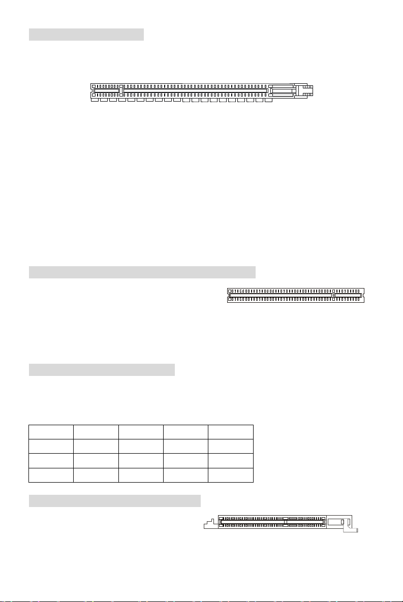
PCI Express x16 Sockel
Der PCI Express x16 Slot verwendet eine serielle Anschlusstechnologie, die sich durch eine
hohe Bandbreite und eine niedrige Anzahl an Pins auszeichnet und die Intels Plattform für
Hochleistungsdesktops mit dem Intel Pentium 4 Prozessor mit HT Technologie unterstützen.
Die PCI Express Architektur stellt eine Hochleistungs- Ein-/Ausgabe- Infrastruktur für Desktop
Plattformen mit Datendurchsätzen zur Verfügung, die bei 2,5 Giga- Übertragungen pro Sekunde
über eine PCI Express x1 Leitung für Gigabit- Lan, TV -Karten, 1394 Kontroller und allgemeine
Ein- und Ausgabe anfängt. Zudem werden Desktopplattformen mit PCI Express Architektur
entworfen, um Höchstleistungen in Bezug auf Videodarstellung, Grafik, Multimedia- und weitere
hoch entwickelte Anwendungen zu bieten. Ferner offeriert die PCI Express Architektur eine
Hochleistungsgrafikinfrastruktur für Desktopplattformen, die die Leistungsfähigkeit bestehender
AGP8x Designs mit Übertragungsraten von 4.0 Gbit/Sek über eine PCI Express 16-fach Leitung
für Grafikkarten verdoppelt, während PCI Express 1-fach Übertragungsraten von 250 MBit/Sek
unterstützt.
Hier können Sie Erweiterungskarten gemäß Ihren Anforderungen einsetzen. Stellen Sie sicher
zuerst den Netzstecker zu ziehen, bevor Sie Erweiterungskarten ein- oder ausbauen.
PCI (Peripheral Component Interconnect) Slots
Die PCI Steckplätze ermöglichen Ihnen den Einsatz
von PCI- Karten, um das System Ihren
Anforderungen anzupassen. Stellen Sie vor dem Einsetzen oder Entnehmen von Karten sicher,
dass Sie den Netzstecker gezogen haben. Studieren Sie bitte die Anleitung zur
Erweiterungskarte, um jede notwendige Hard - oder Softwareeinstellung für die
Erweiterungskarte vorzunehmen, sei es an Steckbrücken (“Jumpern”), Schaltern oder im BIOS.
PCI Interrupt Request Routing
Die IRQs (Interrupt Request Lines) sind Hardwareverbindungen, über die Geräte
Interruptsignale an den Prozessor senden können. Die PCI IRQ Pins sind typischer Weise in der
folgenden Art mit den PCI Bus Pins INT A# ~ INT D# verbunden:
Reihenf.1 Reihenf.2 Reihenf.3 Reihenf.4
PCI Slot 1 INT B# INT C# INT D# INT A#
PCI Slot 2 INT C# INT D# INT A# INT B#
PCI Slot 3 INT D# INT A# INT B# INT C#
AGR (Advance Graphics Riser) Slot
Beim AGR (Advance Graphics Riser) Sockel
handelt es sich um eine spezielle Entwicklung,
die nur hierzu kompatible AGP Grafikkarten
unterstützt.
38
Page 43

Liste kompatibler Grafikkarten
No. Hersteller Modelbezeichnung
1 Alvatron FX5700U GeForce FX5700 Ultra 128MB/DDR SDRAM
2 ATI Fire GL 8800 Fire GL 8800 128MB/SDRAM
3 ATI Radeon 9800 XT Radeon 9800 XT 256MB/DDR SDRAM
4 GAINWARD GFX 5900 Ultra GeForce 4 FX 5900 U 256MB/DDR SDRAM
5 Gigabyte GV-R9200 Radeon 9200 128MB/DDR SDRAM
6 Gigabyte GV-N57L128D GeForce FX5700LE 128MB/DDR SDRAM
7 Leadtek Winfast A360LE TD GeForce FX5700LE 128MB/DDR SDRAM
8 Leadtek Winfast A400GT TDH GeForce 6800GT 256MB/DDR SDRAM
9 MSI MS-8863 GeForce 4 MX 460 64MB/SDRAM
10 MSI MS-8907 GeForce FX 5200 64MB/DDR SDRAM
11 MSI MS-8911 GeForce FX 5200 128MB/DDR SDRAM
12 MSI MS-8919 GeForce FX 5200 128MB/DDR SDRAM
13 MSI MS-8923 GeForce FX 5200 Ultra 128MB/DDR SDRAM
14 MSI MS-8929 GeForce FX 5900 128MB/DDR SDRAM
15 MSI MS-8931 GeForce FX 5600 Ultra 128MB/DDR SDRAM
16 MSI MS-8936 GeForce4 MX4000 64MB/DDR SDRAM
17 MSI MS-8936 GeForce FX5500 128MB/DDR SDRAM
18 MSI MS-8946 GeForce FX 5950 Ultra 256MB/DDR SDRAM
19 MSI MS-8959 GeForce FX5700LE 128MB/DDR SDRAM
20 MSI MS-8975 Nvidia GeForce 6800 128MB/DDR SDRAM
21 Unika FX5200 SP5208 GeForce FX5200 64MB/DDR SDRAM
22 MSI MS-8952 ATI Radeon 9250 128MB/DDR SDRAM
23 Power Color R92U-LC3 Radeon 9250 128MB/DDR SDRAM
24 Power Color RV6DE-NB3 Radeon 7000 64MB/DDR SDRAM
25 ATI Radeon LE Radeon LE DDR 32MB/DDR SGRAM
26 ATI Radeon 7500 LE Radeon DDR 64MB/SDRAM
27 ATI Fire GL 8700 Fire GL 8700 64MB/DDR SDRAM
28 ATI Radeon 9000 Pro Radeon DDR 64MB/DDR SDRAM
29 ATI Radeon 9500 Radeon 9500 64MB/DDR SDRAM
30 ATI Radeon 9700 Radeon 9700 128MB/DDR SDRAM
31 ASUS AGP-V7700 Deluxe GeForce 2 GTS 32MB/DDR SGRAM
32 ASUS V8440 GeForce 4 Ti 4400 128MB/SDRAM
33 ASUS V8460 Ultra GeForce 4 Ti 4600 128MB/SDRAM
34 Creative
35 ELSA Gladiac 517 SV GeForce 4 MX420 64MB/SDRAM
36 ELSA Gladiac 528 Ultra GeForce 4 Ti 4200 128MB/DDR SDRAM
3D Blaster 5 RX9700
VGA Chip VGA Speicher
Radeon 9700 128MB/SGRAM
MS-7113
Ergebnis Treiber Ver.
Pass 6.14.10.7125
Pass 6.12.10.3056
Pass 6.14.10.6476
Pass 6.14.10.7125
Pass 6.14.10.6512
Pass 6.14.10.7125
Pass 6.14.10.7125
Pass 6.14.10.7125
Pass 6.14.10.2958
Pass 6.14.10.7125
Pass 6.14.10.7125
Pass 6.14.10.7125
Pass 6.14.10.7125
Pass 6.14.10.7125
Pass 6.14.10.7125
Pass 6.14.10.6681
Pass 6.14.10.7125
Pass 6.14.10.7125
Pass 6.14.10.7125
Pass 6.14.10.7125
Pass 6.14.10.7125
Pass 6.14.10.6512
Pass 6.14.10.6505
Pass 6.13.10.6476
Pass 6.13.10.6153
Pass 6.13.10.6153
Pass 6.12.10.3051
Pass 6.14.10.6458
Pass 6.14.10.6458
Pass 6.14.10.6458
Pass 6.14.10.2958
Pass 6.14.10.2958
Pass 6.14.10.2958
Pass 6.14.10.6458
Pass 6.14.10.2958
Pass 6.14.10.6681
39
Page 44

37 GAINWARD GeForce 4 MX460 64MB/DDR
38 GAINWARD GeForce 4 MX440T 64MB/SDRAM
39 GAINWARD GeForce 4 MX440 64MB/DDR SDRAM
40 Leadtek Winfast GeForce3 Titanium 500 TD 64MB/SDRAM
41 Leadtek Winfast A170 TH GeForce 4 MX 420 64MB/SDRAM
42 Leadtek Winfast A250 TD GeForce 4 4400 Ti 128MB/SDRAM
43 MSI MS-8806 Nvidia RIVA TNT2 32MB/SDRAM
44 MSI MS-8831 GeForce GTS Pro 64MB/SDRAM
45 MSI MS-8847 GeForce 4 MX 440 64MB/DDR SDRAM
46 MSI MS-8851 GeForce 3 Ti 200 64MB/SDRAM
47 MSI MS-8852 GeForce 2 MX 100/200 32MB/SDRAM
48 MSI MS-8860 GeForce 4 MX 440 64MB/SDRAM
49 MSI MS-8861 GeForce 4 MX 440 64MB/SDRAM
50 MSI MS-8870 GForce 4 Ti 4200 64MB/DDR SDRAM
51 MSI MS-8872 GeForce 4 Ti 4600 128MB/DDR SDRAM
52 MSI MS-8879 GeForce 4 Ti 4200 64MB/DDR SDRAM
53 MSI MS-8883 GeForce 4 MX 460 128MB/DDR SDRAM
54 MSI MS-8888 GeForce 4 MX 440 64MB/DDR SDRAM
55 MSI MS-8889 GeForce 4 Ti 4200 128MB/DDR SDRAM
56 MSI MS-8890 GeForce 4 MX 440 64MB/DDR SDRAM
57 MSI MS-8891 GeForce 4 MX 440 128MB/DDR SDRAM
58 MSI MS-8894 GeForce 4 Ti 4200 128MB/DDR SDRAM
59 MSI MS-8895 GeForce 4 MX 440 64MB/DDR SDRAM
60 MSI MS-8900 GeForce 4 Ti 4800 SE 128MB/DDR SDRAM
61 MSI MS-8904 GeForce FX 5800 128MB/DDR SDRAM
62 MSI MS-8948 GeForce FX 5700 128MB/DDR SDRAM
63 NS GF4 MX440 GeForce 4 MX 440 64MB/DDR SDRAM
64 Pixel View MVGA-NBG25GA GeForce 4 Ti 4200 128MB/SDRAM
65 Triplex Xabre Pro 64MB/SDRAM
66 Triplex Millennium Silver GeForce 4 MX 440 64MB/DDR
67 Triplex SIS Sabre 600 Ultra 64MB/DDR SDRAM
68 VINIX VINIX VX-3340 XABRE400 64MB/DDR SDRAM
69 MSI MS-8988 GeForce 6600 256MB/DDR SDRAM
Für neueste Informationen suchen Sie bitte
http://www.msi.com.tw/program/products/mainboard/mbd_index.php auf.
40
Pass 6.14.10.5673
Pass 6.14.10.2958
Pass 6.14.10.6681
Pass 6.14.10.2958
Pass 6.14.10.2958
Pass 6.14.10.2958
Pass 6.14.10.6681
Pass 6.14.10.2958
Pass 6.14.10.5673
Pass 6.14.10.6681
Pass 6.14.10.6681
Pass 6.14.10.2958
Pass 6.14.10.2958
Pass 6.14.10.2958
Pass 6.14.10.2958
Pass 6.14.10.2958
Pass 6.14.10.2958
Pass 6.14.10.5673
Pass 6.14.10.6681
Pass 6.14.10.5673
Pass 6.14.10.6681
Pass 6.14.10.6681
Pass 6.14.10.6681
Pass 6.14.10.6681
Pass 6.14.10.5673
Pass 6.14.10.6681
Pass 6.14.10.2958
Pass 6.14.10.2958
Pass 6.13.10.3080
Pass 6.14.10.2958
Pass 6.13.10.3080
Pass 6.13.10.3080
Pass 7.1.2.5
Page 45

BIOS Setup
Nach dem Einschalten beginnt der Computer den POST (Power On Self Test Selbstüberprüfung nach Anschalten). Sobald die Meldung unten erscheint, drücken Sie die Taste
<Entf>(<Del>), um das Setup aufzurufen.
DEL: Setup F11: Boot Menu
Wenn die Nachricht verschwindet, bevor Sie reagieren und Sie möchten immer noch ins Setup,
starten Sie das System neu, indem Sie es erst AUS- und danach wieder ANSCHALTEN, oder die
“RESET”-Taste am Gehäuse betätigen. Sie können das System außerdem neu starten, indem
Sie gleichzeitig die Tasten <Strg>,<Alt> und <Entf> drücken (bei manchen Tastaturen
<Ctrl>,<Alt> und <Del>).
Hauptmenü
Standard CMOS Features
In diesem Menü können Sie die Basiskonfiguration Ihres Systems anpassen, so z.B. Uhrzeit,
Datum usw.
Advanced BIOS Features
Verwenden Sie diesen Menüpunkt, um Award -eigne weitergehende Einstellungen an Ihrem
System vorzunehmen.
Advanced Chipset Features
Verwenden Sie dieses Menü, um die Werte in den Chipsatzregistern zu ändern und die
Leistungsfähigkeit Ihres Systems zu optimieren.
Integrated Peripherals
Verwenden Sie dieses Menü, um die Einstellungen für in das Board integrierte Peripheriegeräte
vorzunehmen.
41
Page 46

Power Management Setup
Verwenden Sie dieses Menü, um die Einstellungen für die Stromsparfunktionen vorzunehmen.
PNP/PCI Configurations
Dieser Eintrag erscheint, wenn Ihr System Plug and Play- Geräte am PCI-Bus unterstützt.
H/W Monitor
Dieser Eintrag gibt den „Gesundheitszustand“ Ihres PCs wieder.
Frequency/Voltage Control
Hier können Sie Einstellungen zu Taktfrequenz und Spannung vornehmen.
Load Optimized Defaults
In diesem Menü können Sie die werkseitigen Einstellungen für stabilen Betrieb laden.
BIOS Setting Password
Verwenden Sie dieses Menü, um das Anwenderkennwort einzugeben.
Save & Exit Setup
Abspeichern der BIOS-Änderungen im CMOS und verlassen des BIOS.
Exit Without Saving
Verlassen des BIOS´ ohne Speicherung, vorgenommene Änderungen verfallen.
Frequency/Voltage Control
Auto Detect CPU Frequency
Ist diese Option aktiv, wird die CPU Frequenz automatisch erkannt. Wird diese Option deaktiviert,
kann die CPU Frequenz manuell über das neue Feld „CPU Frequency Setting” eingestellt
werden.
42
Page 47

CPU Frequency Setting
Dieser Eintrag erlaubt die Einstellung der Frequenz für den Front Side Bus (FSB), wie auch
Übertaktung des Prozessors durch einen höhere Taktung der FSB Frequenz. Wählen Sie eine
Einstellung zwischen [100]~[355] MHz. Standardeinstellungen sind: [133], [200].
Auto Detect DRAM Frequency
Dieser Eintrag dient der Einstellung der DRAM Frequenz. Ist diese Option deaktiviert, kann über
den Eintrag “CPU:DRAM Frequency Ratio” die Einstellung manuell vorgenommen werden.
CPU:DRAM Frequency Ratio
Der Eintrag „CPU:DRAM Frequency Ratio” erlaubt das Einstellen des Frequenzverhältnisses zu
CPU:DRAM. Die Parameter ergeben sich aus den CPU und DRAM Frequenzen.
Spread Spectrum
Pulsiert der Taktgenerator des Motherboards, erzeugen die Extremwerte (Spitzen) der Pulse EMI
(Elektromagnetische Interferenzen). Die Spread Spectrum Funktion reduziert die erzeugten EMI,
indem die Pulse so moduliert werden, das die Pulsspitzen zu flacheren Kurven reduziert werden.
Sollten Sie keine Probleme mit Interferenzen haben, belassen Sie es bei der Einstellung
[Disabled] (ausgeschaltet), um bestmögliche Systemstabilität und -leistung zu gewährleisten.
Stellt für sie EMI ein Problem dar, aktivieren Sie („Enabled“) zur Verringerung Spread Spectrum.
Denken Sie daran Spread Spectrum zu deaktivieren, wenn Sie übertakten, da sogar eine leichte
Schwankung eine vorübergehende Taktsteigerung erzeugen kann, die gerade ausreichen mag,
um Ihren übertakteten Prozessor zum einfrieren zu bringen.
43
Page 48

Load Optimized Defaults
Hier können Sie die BIOS- Voreinstellungen für den stabilen Betrieb laden, die der
Mainboardhersteller vorgibt.
Um eine komplette Einführung in das BIOS und seine Einstellungen zu erhalten, suchen Sie bitte
die MSI Website http://www.msi.com.tw auf.
44
Page 49

简介
BIOS
DIMM1DIMM
2
BATT
AGR Slot
感谢您购买 649 Neo-V(MS-7113 v1.X)Series ATX 主板。649 Neo-V Series 是基于 SiS® 649
和 SiS® 965L 芯片组,为 LGA775封装的 Intel ® P4 Prescott 533MHz/800MHz 处理器量身定做的
高性能主板,649 Neo-V Series 提供了高性能、专业化的桌面平台解决方案。
布局
T: mouse
B: keyboard
CPUFAN1
JPW1
ATX1
IDE1
IDE2
T:
Line-In
Line-Out
M:
B:Mic
SiS
649
Chipset
Winbond
W83627THF
Codec
+
JBAT1
JAUD1
CD1
PCI Slot 1
PCI Slot 2
PCI Slot 3
PCI_E 1
FDD1
JUSB1
Chipset
JUSB2
SiS
965L
SATA2
JFP1
SYSFAN1
SATA1
JFP2
45
Page 50

规格
CPU
l 支持 LGA775 封装的 Intel Pentium 4 / Celeron D Prescott 处理器
l 支持到 Pentium 4 3XX, 5XX, 6XX 或更高频率处理器
l 支持 Intel Hyper-Threading 超线程技术
l 要了解关于 CPU 的最新信息,请访问
http://www.msi.com.tw/program/products/mainboard/mbd/pro_mbd_cpu_support.php
芯片组
l SiS® 649 芯片组
- 支持 FSB 533/ 800 MHz.
- 支持 PCI Express x 16界面
- 支持 DDR333/ DDR400 内存界面
l SiS® 965L 芯片组
- 高速 USB(USB2.0)控制器,480Mb/sec, 8 个端口
- 2个Serial ATA 端口,传输速度可高达 1.5Gb/s
- 2通道 Ultra ATA 66/100 总线 Master IDE 控制器
- PCI Master v2.3,I/O APIC
- 支持 ACPI 和传统 APM 电源管理
主内存
l 支持 2 条无缓冲的 DDR SDRAM 模组
l 支持无 ECC 的内存,最高容量为 2GB
l 支持 DDR333/ DDR400 MHz
(要了解内存模组支持的更新详情,请访问
http://www.msi.com.tw/program/products/mainboard/mbd/pro_mbd_trp_list.php )
插槽
l 1条PCI Express x16 插槽(支持 PCI Express Bus 规格 v1.0a)
l 1条AGR(高级图像扩展卡)插槽,兼容 AGP VGA 卡
l 3条PCI 2.3 32-bit PCI 总线插槽(支持 3.3v/5v PCI 总线界面)
板载 IDE
l 1条Ultra DMA 66/100/133 IDE 控制器集成于 965L 中
- 支持 PIO、Bus Master 工作模式
- 最多可支持 4 个 Ultra ATA 设备
l Serial ATA/150 控制器集成于 965L 中
- 传输速度可高达 150MB/sec
- 最多可支持 2 个 Serial ATA 设备
46
Page 51

板载周边
l 板载周边包括:
- 1个软驱接口,支持 1 台 360K, 720K, 1.2M, 1.44M 和 2.88 Mbytes 的软驱
- 1个串行端口(后置* 1)和 1个支持 SPP/EPP/ECP 模式的并行端口
- 8个USB 2.0 端口(后置* 4/ 前置* 4)
- 3个音频(Line-In/Line-Out/Mic)插孔
- 1个RJ-45 LAN 插孔
音频
l AC97连接控制器,集成于 965L 芯片组
l 6-声道音频编解码 ADI AD1888
- 符合 AC97 v2.3规格
- 满足 PC2001音频性能要求
LAN
l Broadcom AC131
- 集成了 Fast Ethernet PHY
- 支持 10Mb/和 100Mb/s
- 兼容 PCI 2.2
- 支持 ACPI 电源管理
BIOS
l 主板的 BIOS 提供“Plug & Play”(即插即用)功能,能够自动侦测周边设备和连接于主板上
的扩展卡
l 主板提供了桌面管理界面(DMI)功能,可记录您主板的规格
规格
l ATX规格尺寸:30.5 cm x 18.5 cm.
固定孔
l 6个固定孔
其他
l 支持 PS/2键盘/鼠标
l 对温度和电压进行硬件监视
47
Page 52

后置面板
Parallel port
Line ln
Line Out
MIC
后置面板提供了以下接口:
Mouse
LAN
USB ports
Keyboard
COM port
USB ports
硬件安装
这一章主要告诉您如何安装 CPU、内存、扩展卡,也会告诉您怎样设置主板上的跳线,并提供连
接外围设备的指导,如鼠标,键盘等。安装时,请谨慎拿各零部件并且按照安装说明的步骤进行。
中央处理器:CPU
本主板支持 LGA775 封装的 Pentium 4 / Celeron D Prescott 处理器。主板使用的是 LGA775封装
的 CPU 插槽,可使 CPU 安装过程简化。当您在安装 CPU 时,请务必确认您使用的 CPU 带有防
过热的散热片和降温风扇。如果您的 CPU 没有散热片和降温风扇,请与销售商联系,购买或索取
以上设备,并在开机之前妥善安装。要了解关于 CPU 的最新信息,请访问
http://www.msi.com.tw/program/products/mainboard/mbd/pro_mbd_cpu_support.php
微星提醒您...
温度过高
温度过高会严重损害
以免过热烧毁。
超频
此主板的设计支持超频。但是,请先确认您的组件在超频过程中可支持非正常设定。我们并不推荐
您在标准规格以外的情况下运行此设备。对于任何非正常的设定或在标准规格以外运行本设备所造
成的损失,我们不予担保。
LGA775 CPU 和风扇的安装(CPU夹子为选配)
当您安装CPU时,请确认CPU带有散热片和风扇放置在CPU顶部,以防止CPU过热。如果您没有
散热片和风扇,请联系经销商以购买和安装。然而请不要忘记使用一些散热胶涂在CPU表面,使
它更好地散热。
请根据以下步骤正确安装 CPU 和风扇。错误的安装可能会引起您 CPU 和主板的损毁。
1. CPU 底部有一个底座保护片,可保护 CPU 底座避免损害。旋转 CPU,使得针脚 1的指示标
2. 取出随带的 CPU 夹子(如右图所示), 并 旋转至与 CPU 相同的方向(针
3. 用双手取下 CPU 的底座保护片(若有的话)。请勿触碰针脚。
CPU
和系统,请务必确认所使用的降温风扇始终能够正常工作,保护
志(黄色三角形)位于左下角。具体情况要根据 CPU 的包装而定。
脚 1的指示标志位于左下角)。
48
CPU
Page 53
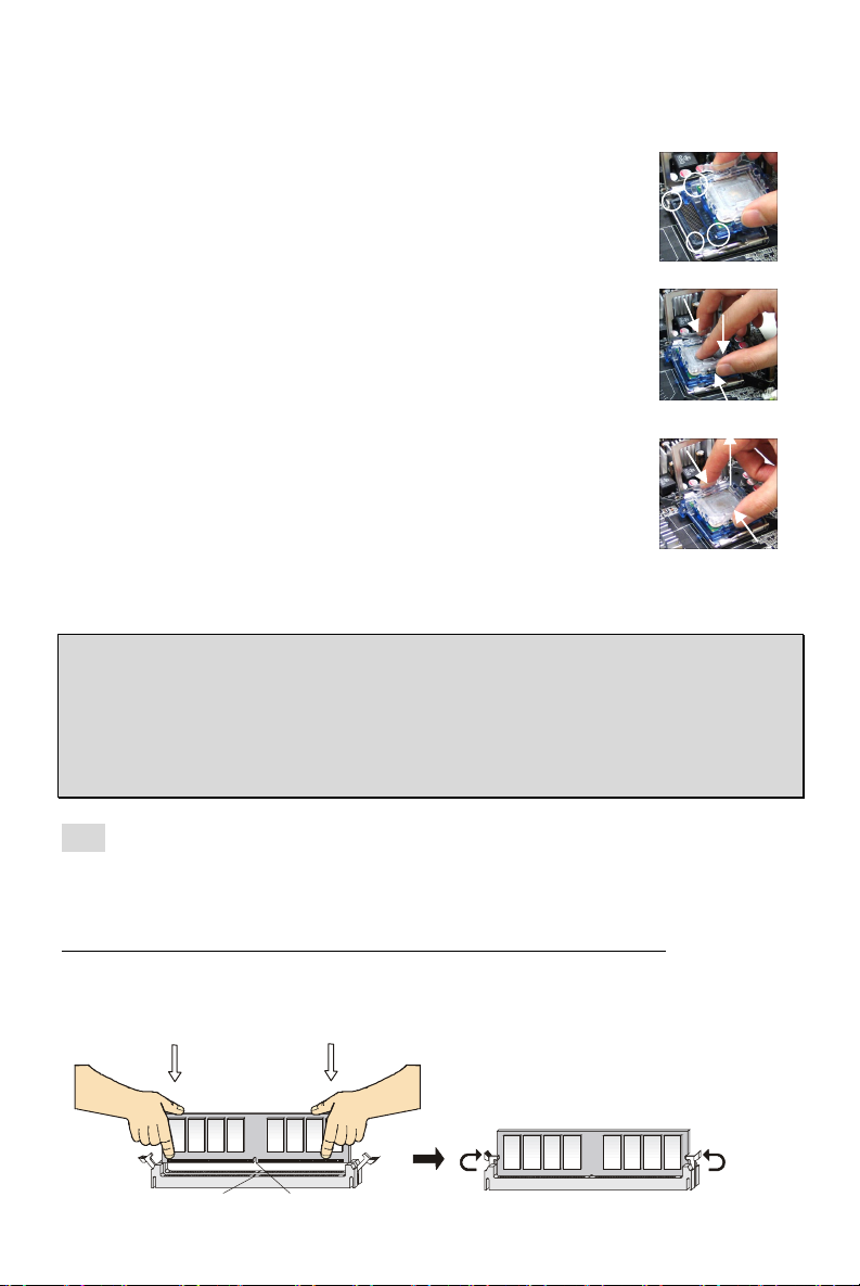
4. 对齐两个针脚 1的指示标志(CPU 和 CPU 夹子上的三角形), 然 后 使 用 CPU 夹子夹在 CPU
Notch
Volt
上方,把夹子两边向中间按,如下图所示。
5. CPU 插槽上有一个塑料保护盖,可保护 CPU 针座避免损害。在安装 CPU 之前,请不要 取 下
此塑料保护盖,以防针脚受损。
6. 取下塑料保护盖,会看到针脚的插槽。
7. 抬起拉杆,打开盖盘。
8. 对齐 CPU 夹子上的三角形标记与 CPU 斜边,对齐 CPU 夹子边缘与插
槽上的钩子。
9. 用拇指和中指把夹子向中间推,以松开 CPU,然后把 CPU 向下按,使
整个模块安装到 CPU 插槽上。
10. CPU 已经安装到插槽中。
11. 目测查看 CPU 是否已固定在插槽中,再用双指取下 CPU 夹子。然后盖
上盖盘。
12. 目测查看 CPU 是否已固定在插槽中,再用双指取下 CPU 夹子。然后盖
上盖盘。
13. 先对齐散热风扇和主板上的孔。把风扇向下推,直到它的 4 个钉钩插入
主板的孔中。
14. 先对齐散热风扇和主板上的孔。把风扇向下推,直到它的 4 个钉钩插入
主板的孔中。
15. 翻转主板,确认钉钩的一端已被正确插入。
注意:若您要取下 CPU,请再次对齐 4 点(请查看第 8 步骤), 并用夹子夹住 CPU 向上提起,以
取出。
微星提醒您…
1.
在您开启系统之前,确认您的
2.
请在
BIOS中H/W Monitor的PC Health Status
3.
请勿触摸
4.
只要
5.
请注意
CPU
插槽针脚,以避免受损。
CPU
尚未安装,请把塑料盖覆在
CPU
的安插/拔取的寿命为20次。因此我们建议您不要频繁地插拔
CPU
风扇已正确安装。
CPU
查看
CPU
温度。
插槽上,以免插槽的针脚受损。
CPU。
内存
主板提供 2 条插槽,可以插入 184-pin无缓冲的 DDR333 / DDR400 DDR SDRAM 内存,支持的
内存最大容量为 2GB。您 至少要安装一条内存在插槽,以保证系统正常工作。(要了解内存模组支
持的更新,请访问
http://www.msi.com.tw/program/products/mainboard/mbd/pro_mbd_trp_list.php )
至少要安装一条内存模组在插槽。内存条可以按任何次序被安装。您 也 可以根据自己的需要,来 安
装单面或双面的内存模组。
安装 DDR 内存
49
Page 54

1. DDR DIMM 内存条的中央仅有一个缺口。
1
3
4
2
GND
GND
1
12
24
13
+3.3V
+3.3V
PS-ON#
PWR OK
1
2. 将 DDR 内存垂直插入 DDR 插槽中,并确保缺口的正确位置。
3. DIMM 插槽两边的塑料卡口会自动闭合。
电源适配器
主板使用 ATX 结构的电源适配器给主板供电。在连接电源适配器之前,请务必确认所有的组件都
已正确安装,并且不会造成损坏。建议您使用功率为 300W 或以上的电源。
ATX 24-Pin 电源接口:ATX1
此接口可连接 ATX 24-Pin电源适配器。在与 ATX 24-Pin 电源适配器
相连时,请务必确认,电源适配器的接头安装方向正确,针脚对应顺
序也准确无误。将电源接头插入,并使其与主板电源接口稳固连接。
若您喜欢,可以使用 20-pin 的 ATX 电源适配器。若您要使用 20-pin
的 ATX 电源适配器,请顺着 pin 1 和 pin 13 插上电源适配器(参阅右
示图例)。 pin 11, 12, 23 和 24 具有防呆设计,以避免安装错误。
ATX 12V 电源接口:JPW1
此 12V 电源接口用于为 CPU供电。
12V
12V
+3.3V
-12V
GND GND
GND GND
GND +5V
GND GND
Res
+5V 5VSB
+5V +12V
+5V +12V
GND NC
+5V
软盘驱动器接口:FDD1
主板提供了一个标准的软盘驱动器接口 FDD,支持 360K, 720K, 1.2M,
1.44M 和 2.88M 的软盘驱动器。
IDE 接口:IDE1/ IDE2
主板有 2 个 32-bit增强 PCI IDE 和 Ultra DMA 66/100 控制器,支持 PIO 模式 0~4, Bus
Master 和 Ultra DMA 66/100 工作模式,且它最多可连接 4个设备,如硬盘、CD-ROM、
120MB 软驱和其他设备。
第一个硬盘必须与 IDE1 接口相连。IDE1可以连接 1 个 Master(主)设备和 1 个 Slave
(从)设备。通过跳线的正确设置,您可以配置第二个硬盘到 Slave(从)模式。
微星提醒您...
如果您打算在一条硬盘线上连接两个硬盘,您必须将第二个硬盘设为从盘。请参考硬盘所附的说明
手册设定主/从盘模式。
由 SiS 965L 控制的 Serial ATA 接口:SATA1/SATA2
此主板的南桥芯片是 SiS 965L,它支持 serial 接口 SATA1、SATA2。
SATA1、SATA2 是高速串行 Serial ATA 端口。每个接口都支持第一代 Serial ATA,数据
速率达到 150 MB/s。两个接口都兼容 Serial ATA1.0 规格。
微星提醒您...
请勿把
serial ATA
数据线折成90度,否则会造成传输时数据的丢失。
7
50
Page 55

CD-In 接口:JCD1
9210
GND
+12V
USB0+
USB1+
USB0C(10)
R
GND
Sensor
Control
JFP1
Power
Switch
Power
Switch
10
JFP2
Power
728
AUD_RET_R
AUD_RET_L(10)
AUD_FPOUT_L(9)
此接口为 CD-ROM 的音频接口。
L
风扇电源接口:CPUFAN1/SYSFAN1
此 4-pin 的 CPUFAN1(处理器风扇)和 3-pin 的 SYSFAN1(系
统风扇)支持+12V 的系统散热风扇,可使用 3-pin 或 4-pin 的
接头。当您将接线接到风扇接头时,请注意红色线为正极,必须接到+12V,而黑色线是接地,必
须接到 GND。如果您的主板有系统硬件监控芯片,您必须使用一个特别设计的支持速度侦测的风
扇方可使用此功能。
微星提醒您...
请询问厂商以使用适当的
CPU
降温风扇。
前置面板接口:JFP1/JFP2
主板提供了 2 组机箱面板和电源开关、指示灯的连接接口 JFP1 和 JFP2。JFP1 是符合 Intel ® I/O
面板连接设计向导的。
LED
2
1 9
HDD
Reset
LED
Speaker
前置音频接口:JAUD1
您可以在前置面板接口 JAUD1 上连接一个音频接口,
JAUD1 是符合 Intel
®
I/O 面板连接设计向导的。
(2)AUD_GND
(1)AUD_MIC
AUD_MIC_BIAS
微星提醒您...
如果您不想使用前置音频,针脚
音频端口。否则后面的
Line-Out
前置 USB 接口:JUSB1/ JUSB2
主板提供 2 个 USB2.0 的接口 JUSB1、JUSB2。USB 2.0 技术提
高数据传输速度,达到 480Mbps,是 USB1.1的 40 倍。它可连接
高速数据传输速率的 USB界面周边设备,如 USB HDD、数码相机、
MP3播放器、打印机、调制解调器等。
微星提醒您...
请勿把
serial ATA
数据线折成90度,否则会造成传输时数据的丢失。
5 & 6, 9 & 10
必须用跳线帽短接,这样输出信号才会转到后面的
音频接口将不起作用。
1
GND
+12V
LED
1
AUD_VCC
Key
HP_ON
AUD_FPOUT_R
USB1- GND
(2)VCC
(1)VCC Key(9)
GND
USB0-
NC
51
Page 56

清除 CMOS 跳线:JBAT1
1
133
322
2
Keep Data
Clear Data
主板上建有一个 CMOS RAM,其中保存的系统配置数据需要通
过一枚外置电池来维持。CMOS RAM 是在每次启动计算机的时
候引导操作系统的。若您想清除保存在 CMOS RAM 中的系统配
置信息,可使用 JBAT1(清除 CMOS 跳线)清除数据。请按照
以下方法清除数据:
微星提醒您...
在系统关闭时,您可通过短接
避免在系统开机时清除
2-3
针脚来清除
CMOS
,这样可能会对主板造成损害。
CMOS
数据。然后,返回到
1
1-2
针短接的状态。请
PCI Express x16 插槽
PCI Express x16 插槽具有高带宽、针脚数目少、串行、相互连接技术等特性,支持使用 HT 超线
程技术、Intel Pentium 4 处理器的 Intel高性能的台式机。
PCI Express 结构为台式机提供了高性能 I/O 基本架构,起始的传输速度为每秒 2.5 Giga,PCI
Express x1 可用于 Gigabit Ethernet(千兆网卡)、 TV 转接卡、1394控制器和普通用途 I/O。同样,
具有 PCI Express 结构的台式机会被应用于视频、图像、多媒体和其他复杂的应用程序。此外,
PCI Express 结构用于图像控制器为台式机提供了高性能的图像基本架构,通 过 PCI Express x16,
性能是现有 APG8x的 2 倍,传输速度达到 4.0 GB/s,而 PCI Express x1 支持的传输速度为 250
MB/s。
您可以根据自己的需要插入扩展卡。要插拔扩展卡,请务必先拔除电源适配器。
PCI(周边设备连接)插槽
PCI 插槽可安装您所需要的扩展卡。当您在安装或拆卸扩展
卡的时候,请务必确认已将电源插头拔除。同时,请仔细阅
读扩展卡的说明文件,安装和设置此扩展卡必须的硬件和软件,比如跳线或 BIOS 设置。
PCI 中断请求队列
IRQ 是中断请求队列和中断请求确认的缩写,将设备的中断信号送到微处理器的硬件列表。PCI
的 IRQ 针脚一般都是连接到如下表所示的 PCI 总线的 INT A# ~ INTD# 引脚:
Order1 Order2 Order3 Order4
PCI Slot 1 INT B# INT C# INT D# INT A#
PCI Slot 2 INT C# INT D# INT A# INT B#
PCI Slot 3 INT D# INT A# INT B# INT C#
52
Page 57

AGR(高级图像扩展卡)插槽
10
11
12
13
14
15
16
17
18
19
20
21
22
23
24
25
26
27
28
29
30
31
32
33
AGR(高级图像扩展卡)插槽可支持 AGP VGA 卡。
兼容的 VGA卡列表
VGA 显卡
No.
制造商
1
Alvatron FX5700U GeForce FX5700 Ultra 128MB/DDR SDRAM
2
ATI Fire GL 8800 Fire GL 8800 128MB/SDRAM
3
ATI Radeon 9800 XT Radeon 9800 XT 256MB/DDR SDRAM
4
GAINWARD GFX 5900 Ultra GeForce 4 FX 5900 U 256MB/DDR SDRAM
5
Gigabyte GV-R9200 Radeon 9200 128MB/DDR SDRAM
6
Gigabyte GV-N57L128D GeForce FX5700LE 128MB/DDR SDRAM
7
Leadtek Winfast A360LE TD GeForce FX5700LE 128MB/DDR SDRAM
8
Leadtek Winfast A400GT TDH GeForce 6800GT 256MB/DDR SDRAM
9
MSI MS-8863 GeForce 4 MX 460 64MB/SDRAM
MSI MS-8907 GeForce FX 5200 64MB/DDR SDRAM
MSI MS-8911 GeForce FX 5200 128MB/DDR SDRAM
MSI MS-8919 GeForce FX 5200 128MB/DDR SDRAM
MSI MS-8923 GeForce FX 5200 Ultra 128MB/DDR SDRAM
MSI MS-8929 GeForce FX 5900 128MB/DDR SDRAM
MSI MS-8931 GeForce FX 5600 Ultra 128MB/DDR SDRAM
MSI MS-8936 GeForce4 MX4000 64MB/DDR SDRAM
MSI MS-8936 GeForce FX5500 128MB/DDR SDRAM
MSI MS-8946 GeForce FX 5950 Ultra 256MB/DDR SDRAM
MSI MS-8959 GeForce FX5700LE 128MB/DDR SDRAM
MSI MS-8975 Nvidia GeForce 6800 128MB/DDR SDRAM
Unika FX5200 SP5208 GeForce FX5200 64MB/DDR SDRAM
MSI MS-8952 ATI Radeon 9250 128MB/DDR SDRAM
Power Color R92U-LC3 Radeon 9250 128MB/DDR SDRAM
Power Color RV6DE-NB3 Radeon 7000 64MB/DDR SDRAM
ATI Radeon LE Radeon LE DDR 32MB/DDR SGRAM
ATI Radeon 7500 LE Radeon DDR 64MB/SDRAM
ATI Fire GL 8700 Fire GL 8700 64MB/DDR SDRAM
ATI Radeon 9000 Pro Radeon DDR 64MB/DDR SDRAM
ATI Radeon 9500 Radeon 9500 64MB/DDR SDRAM
ATI Radeon 9700 Radeon 9700 128MB/DDR SDRAM
ASUS AGP-V7700 Deluxe GeForce 2 GTS 32MB/DDR SGRAM
ASUS V8440 GeForce 4 Ti 4400 128MB/SDRAM
ASUS V8460 Ultra GeForce 4 Ti 4600 128MB/SDRAM
型号名称 VGA芯片 VGA 内存
MS-7113
结果 驱动版本
Pass 6.14.10.7125
Pass 6.12.10.3056
Pass 6.14.10.6476
Pass 6.14.10.7125
Pass 6.14.10.6512
Pass 6.14.10.7125
Pass 6.14.10.7125
Pass 6.14.10.7125
Pass 6.14.10.2958
Pass 6.14.10.7125
Pass 6.14.10.7125
Pass 6.14.10.7125
Pass 6.14.10.7125
Pass 6.14.10.7125
Pass 6.14.10.7125
Pass 6.14.10.6681
Pass 6.14.10.7125
Pass 6.14.10.7125
Pass 6.14.10.7125
Pass 6.14.10.7125
Pass 6.14.10.7125
Pass 6.14.10.6512
Pass 6.14.10.6505
Pass 6.13.10.6476
Pass 6.13.10.6153
Pass 6.13.10.6153
Pass 6.12.10.3051
Pass 6.14.10.6458
Pass 6.14.10.6458
Pass 6.14.10.6458
Pass 6.14.10.2958
Pass 6.14.10.2958
Pass 6.14.10.2958
53
Page 58

34
35
36
37
38
39
40
41
42
43
44
45
46
47
48
49
50
51
52
53
54
55
56
57
58
59
60
61
62
63
64
65
66
67
68
69
Creative
ELSA Gladiac 517 SV GeForce 4 MX420 64MB/SDRAM
ELSA Gladiac 528 Ultra GeForce 4 Ti 4200 128MB/DDR SDRAM
GAINWARD GeForce 4 MX460 64MB/DDR
GAINWARD GeForce 4 MX440T 64MB/SDRAM
GAINWARD GeForce 4 MX440 64MB/DDR SDRAM
Leadtek Winfast GeForce3 Titanium 500 TD 64MB/SDRAM
Leadtek Winfast A170 TH GeForce 4 MX 420 64MB/SDRAM
Leadtek Winfast A250 TD GeForce 4 4400 Ti 128MB/SDRAM
MSI MS-8806 Nvidia RIVA TNT2 32MB/SDRAM
MSI MS-8831 GeForce GTS Pro 64MB/SDRAM
MSI MS-8847 GeForce 4 MX 440 64MB/DDR SDRAM
MSI MS-8851 GeForce 3 Ti 200 64MB/SDRAM
MSI MS-8852 GeForce 2 MX 100/200 32MB/SDRAM
MSI MS-8860 GeForce 4 MX 440 64MB/SDRAM
MSI MS-8861 GeForce 4 MX 440 64MB/SDRAM
MSI MS-8870 GForce 4 Ti 4200 64MB/DDR SDRAM
MSI MS-8872 GeForce 4 Ti 4600 128MB/DDR SDRAM
MSI MS-8879 GeForce 4 Ti 4200 64MB/DDR SDRAM
MSI MS-8883 GeForce 4 MX 460 128MB/DDR SDRAM
MSI MS-8888 GeForce 4 MX 440 64MB/DDR SDRAM
MSI MS-8889 GeForce 4 Ti 4200 128MB/DDR SDRAM
MSI MS-8890 GeForce 4 MX 440 64MB/DDR SDRAM
MSI MS-8891 GeForce 4 MX 440 128MB/DDR SDRAM
MSI MS-8894 GeForce 4 Ti 4200 128MB/DDR SDRAM
MSI MS-8895 GeForce 4 MX 440 64MB/DDR SDRAM
MSI MS-8900 GeForce 4 Ti 4800 SE 128MB/DDR SDRAM
MSI MS-8904 GeForce FX 5800 128MB/DDR SDRAM
MSI MS-8948 GeForce FX 5700 128MB/DDR SDRAM
NS GF4 MX440 GeForce 4 MX 440 64MB/DDR SDRAM
Pixel View MVGA-NBG25GA GeForce 4 Ti 4200 128MB/SDRAM
Triplex Xabre Pro 64MB/SDRAM
Triplex Millennium Silver GeForce 4 MX 440 64MB/DDR
Triplex SIS Sabre 600 Ultra 64MB/DDR SDRAM
VINIX VINIX VX-3340 XABRE400 64MB/DDR SDRAM
MSI MS-8988 GeForce 6600 256MB/DDR SDRAM
3D Blaster 5 RX9700
Radeon 9700 128MB/SGRAM
Pass 6.14.10.6458
Pass 6.14.10.2958
Pass 6.14.10.6681
Pass 6.14.10.5673
Pass 6.14.10.2958
Pass 6.14.10.6681
Pass 6.14.10.2958
Pass 6.14.10.2958
Pass 6.14.10.2958
Pass 6.14.10.6681
Pass 6.14.10.2958
Pass 6.14.10.5673
Pass 6.14.10.6681
Pass 6.14.10.6681
Pass 6.14.10.2958
Pass 6.14.10.2958
Pass 6.14.10.2958
Pass 6.14.10.2958
Pass 6.14.10.2958
Pass 6.14.10.2958
Pass 6.14.10.5673
Pass 6.14.10.6681
Pass 6.14.10.5673
Pass 6.14.10.6681
Pass 6.14.10.6681
Pass 6.14.10.6681
Pass 6.14.10.6681
Pass 6.14.10.5673
Pass 6.14.10.6681
Pass 6.14.10.2958
Pass 6.14.10.2958
Pass 6.13.10.3080
Pass 6.14.10.2958
Pass 6.13.10.3080
Pass 6.13.10.3080
Pass 7.1.2.5
要了解更新的信息,请访问 http://www.msi.com.tw/program/products/mainboard/mbd_index.php
54
Page 59

BIOS 设置
计算机加电后,系统将会开始 POST (加电自检)过程。当屏幕上出现以下信息时,按<DEL>键
即可进入设定程序。
DEL: Setup F11: Boot Menu
如果信息在您做出反应前就消失了,而您仍需 要 进 入 Setup,请关机后再开机或按机箱上的 Reset
键, 重启您的系统。您也可以同时按下<Ctrl>、<Alt>和<Delete>键来重启系统。
主页面
Standard CMOS Features(标准 CMOS 特性设定)
使用此菜单可对基本的系统配置进行设定。如时间,日期等。
Advanced BIOS Features(高级 BIOS 特性设定)
使用此菜单可对 AMI®系统的高级特性进行设定。
Advanced Chipset Features(高级芯片组特性设定)
使用此菜单可以修改芯片组寄存器的值,优化系统的性能表现。
Power Management Setup(电源管理特性设定)
使用此菜单可以对系统电源管理进行特别的设定。
PNP/PCI Configurations(PnP/PCI配置)
此项仅在您系统支持 PnP/PCI 时才有效。
Integrated Peripherals(整合周边设定)
使用此菜单可以对周边设备进行特别的设定。
H/W Monitor(硬件监控状态)
此项显示了您 PC 的健康状态。
55
Page 60

Frequency/Voltage Control(频率/电压控制)
使用此菜单可以进行频率和电压的特别设定。
Set Supervisor Password(设置管理员密码)
使用此菜单可进行管理员密码设置。
Set User Password(设置用户密码)
使用此菜单可进行用户密码设置。
Load High Performance Defaults(载入高性能设置缺省值)
使用此菜单可以载入系统优化性能设置的 BIOS 值,但此缺省值可能会影响系统的稳定性。
Load BIOS Setup Defaults(载入 BIOS 缺省值)
选择此项可载入工厂设置的 BIOS 系统设定缺省值。
Save & Exit Setup(保存后退出)
保存对 CMOS 的修改,然后退出 Setup 程序。
Exit Without Saving(不保存退出)
放弃对 CMOS 的修改,然后退出 Setup 程序。
56
Page 61

频率/电压控制
Auto Detect CPU Frequency(自动侦测 CPU频率)
此项可让系统自动侦测 CPU 频率。当您设置此项为[Disabled],则以下的“CPU Frequency Setting”
项可调整。
CPU Frequency Setting(CPU 频率设置)
此项可让您选择 CPU 的前端系统总线时钟频率,通过调整前端系统总线到较高频率以进行超频。
选择范围:[100]~[355]。缺省设定值有:[133], [200]。
Auto Detect DRAM Frequency(自动 侦测 DRAM 频率)
此项可自动侦测 DRAM 频率。当您设置此项为[Disabled],则以下的“CPU:DRAM Frequency
Ratio”项可调整。
CPU:DRAM Frequency Ratio(CPU:DRAM 倍频)
此项可让您调整 CPU:DRAM的倍频。此设定选项是根据 CPU 和 DRAM 的频率而定。
Spread Spectrum(频展)
当主板上的时钟震荡发生器工作时,脉冲的极值(尖峰)会产生 EMI(电磁干扰)。频率范围设定
功能可以降低脉冲发生器所产生的电磁干扰,所以脉冲波的尖峰会衰减为较为平滑的曲线。如 果 您
没有遇到电磁干扰问题,将此项设定为[Disabled],这样可以优化系统的性能表现和稳定性。但是
如果您被电磁干扰问题困扰,请将此项设定为[Enabled],这样可以减少电磁干扰。注意,若您超
频使用,必须将此项禁用。因为即使是微小的峰值漂移(抖动)也会引入时钟速度的短暂突发,这
样会导致您超频的处理器锁死。
57
Page 62

载入 BIOS 设置缺省值
您可载入主板制造商提供的 BIOS 设置缺省值,以得到最稳定的系统性能。
要了解完整的 BIOS 简介和设置信息,请访问微星网站 http://www.msi.com.tw.
58
Page 63

簡介
BIOS
DIMM1DIMM
2
BATT
AGR Slot
感謝您選購 649 Neo-V (MS-7113 v1.X) ATX 系列主機板,649 Neo-V 系列主機板係採用SiS® 649
及 SiS® 965L 晶片組,以期提供系統最佳化效能。並針對新一代的 Intel® P4 Prescott 533/
800MHz(LGA775插槽)處理器來設計的,故 649 Neo-V 系列可提供您高效能及專業的桌上型電腦
平台解決方案。
主機板配置圖
T: mouse
B: keyboard
CPUFAN1
JPW1
IDE2
ATX1
IDE1
T:
Line-In
Line-Out
M:
B:Mic
SiS
649
Chipset
PCI Slot 1
PCI Slot 2
PCI Slot 3
PCI_E 1
FDD1
JUSB1
Chipset
JUSB2
SiS
965L
SATA2
JFP1
SYSFAN1
SATA1
JFP2
Winbond
W83627THF
+
Codec
JBAT1
CD1
JAUD1
59
Page 64

主機板規格
中央處理器
l 支援 LGA775 封裝的 Intel Pentium 4/ Celeron Prescott 處理器。
l 支援至 Pentium 4 3XX, 5XX, 6XX 系列處理器或更高時脈。
l 支援 Intel Hyper-Threading(超執行緒)技術。
l 有關最新的 CPU 訊息,請您至微星科技網站
http://www.msi.com.tw/program/products/mainboard/mbd/pro_mbd_cpu_support.php
晶片組
l SiS® 649 晶片
- 支援 FSB 533/ 800 MHz外頻時脈。
- 支援 PCI Express x 16界面卡。
- 支援 DDR333/ DDR400 等記憶體。
l SiS® 965L 晶片
- 高速 USB (萬用串列匯流排2.0 版)控制器,480Mb/秒,八個連接埠。
- 二個 Serial ATA 連接埠傳輸速度可達 1.5Gb/秒。
- 二個 Ultra ATA 66/100/133 主控模式 IDE 匯流排控制器。
- PCI 主控模式 v2.3 版, I/O APIC。
- 同時支援 ACPI進階電源管理方式及支援 APM 傳統的電源管理方式。
記憶體
l 支援兩條 unbuffered 的 DDR SDRAM 記憶體(DIMM模組)。
l 支援高達 2GB 的記憶體容量(non-ECC)。
l 支援雙通道DDR333/ DDR400 MHz 的記憶體。
(有關最新的記憶體模組訊息,請您至微星科技網站
http://www.msi.com.tw/program/products/mainboard/mbd/pro_mbd_trp_list.php )
插槽
l 一個 PCI Express x16 插槽(支援 PCI Express 遵循匯流排 1.0a 版規格)。
l 一個 AGR (進階繪圖卡座) 同時相容於 AGP VGA 繪圖加速卡。
l 三個 PCI 2.3,32-位元 PCI匯流排插槽(支援 3.3v/5v PCI 匯流排介面卡)。
內建 IDE
l 一個 Ultra DMA 66/100/133 IDE 控制器整合於 965L晶片之中。
- 支援 PIO、主控式匯流排操作模式。
- 可連接多達二部 Ultra ATA 裝置。
l 串列式(SATA),Serial ATA/150 控制器亦整合於 965L 晶片之中。
- 高逹 150MB/每秒的傳輸速度。
- 可連接至二部 SATA 裝置。
60
Page 65

內建週邊輸出
l 內建週邊包括:
- 一個軟碟機埠,可支援一部 360K/720K/1.2M/1.44M/2. 88MB 規格的軟碟機。
- 一個序列埠(背板*1)及一個平行埠,可支援 SPP/EPP/ECP 模式。
- 八個 USB2.0 版連接埠(背板*4/面板*4)。
- 三個音效輸入/音效輸出/麥克風輸入埠。
- 一個 RJ-45 網路連接埠。
音效
l AC97連接控制器整合在 965L 晶片之中。
l 6通道音效晶片(ADI AD1888)。
- 符合 AC97 v2.3規格。
- 符合 PC2001規格對聲音效能的要求。
區域網路 LAN
l 寬頻通訊 Broadcom AC131
- 整合了高速乙太網路 Fast Ethernet PHY 於單晶片之中。
- 支援 10Mb/s 及 100Mb/s 兩種模式。
- 遵從 PCI v2.2。
- 支援 ACPI 電源管理模式。
BIOS
l 主機板 BIOS 提供「隨插即用」功能,可自動偵測板上的週邊裝置及擴充卡。
l 本主機板提供桌面管理介面(DMI)功能,可記錄主機板的規格。
尺寸
l ATX規格:30.5 公分(長)x 18.5公分(寬)。
裝機孔
l 六個裝機孔。
其他
l 支援 PS/2介面滑鼠/鍵盤。
l 硬體監控,監控温度及電壓。
61
Page 66

背板
連接埠
音效輸入
音效輸出
區域
主機板後面的背板提供下列各項連接器:
滑鼠
平行埠
網路
USB
連接埠
麥克風
鍵盤
序列埠
USB
硬體安裝
本章將教您安裝中央處理器、記憶體模組、擴充卡及設定主機板上的跨接器,附帶並告訴您如何連
接滑鼠鍵盤等週邊裝置,進行安裝時請小心處理零組件並遵守安裝步驟。
中央處理器(CPU)
本主機板支援 Intel Pentium 4/ Celeron D Prescott處理器,所使用的 CPU 插槽稱之為 LGA775。
當您在安裝 CPU 時,請確認附有散熱器與冷卻風扇以防止 CPU 過熱。如果沒找到散熱器與冷卻
風扇,請洽詢經銷商購買,並在啟動電腦之前,將散熱器正確地安裝在您的主機板上。
有關最新的 CPU 訊息,請您至微星科技網站:
http://www.msi.com.tw/program/products/mainboard/mbd/pro_mbd_cpu_support.php.
MSI 提醒您...
溫度過高
溫度過高將會嚴重損壞您的
發生過熱的情形。
超頻使用
本主機板儘管設計成為可超頻運作。然而當您將其調整為超頻運作時,請確認您的系統元件及週邊
是可以忍受如此非正常的設定。任何在非本產品規格建議下的運作方式,我們將不保證其造成的損
壞及運轉時的風險。
安裝 LGA775 規格的中央處理器及風扇(CPU 扣環是選擇性備配)
當您在安裝 CPU 時,請確認附有散熱器與冷卻風扇以防止 CPU 過熱。如果沒找到散熱器與冷卻
風扇,請洽詢經銷商購買,並在啟動電腦之前,將散熱器正確地安裝在您的主機板上。同時,別忘
了在處理器(CPU)上均勻的塗上散熱器所附的散熱膏以提昇散熱的效果。
下列步驟將會正確地引導您 CPU 散熱風扇的安裝,錯誤的安裝方式將導致您主機板及 CPU 的損
壞。
1. 在主機板的CPU 底座上有一個方蓋子保護著 CPU 底座的接腳避免受損。把第一腳指示器(黃
2. 取出 CPU 所附的環扣(如右圖所示) 然後將其轉至與 CPU 相同的方向(第
3. 以雙手移去方形保護蓋,請注意不要觸碰到針腳。
CPU
及系統,請確保您的散熱風扇可以正常運作,以保護
色的三角形)翻轉至左方底部,如此一來方能便於CPU 的安裝。
一腳指示器是在左方底部)。
CPU
,避免
62
Page 67

4. 對齊兩個針腳 1 指示器(在CPU 及 CPU 環扣上的三角形),用 CPU 環扣將 CPU 夾起來,從
Notch
Volt
環扣的兩側往內壓,如箭頭所示。
5. CPU 底座上有一個方蓋子保護著 CPU 底座的接腳避免受損。在您未安裝CPU的情況下, 務
必將其蓋住以保護底座針腳避免受損。
6. 從側邊的拉桿移去蓋子,就看得到底座針腳。
7. 將裝載拉桿拉起然後打開裝載盤。
8. 正確地對準 CPU環扣上的三角點於 CPU 溝槽,而且 CPU 的方形環扣
對準底座固定鈎。
9. 用您的姆指及中指將環扣卡入CPU 底座,然後食指向下壓住讓整個模
組完整的安裝在底座。
10. 如此一來,處理器已完整地安裝在底座上。
11. 目視查看一下 CPU 是否緊密的安裝在底座,然後以兩指移去 CPU 環
扣,再來蓋上裝載盤。
12. 輕輕的壓下裝載拉桿,且確定拉桿有卡入固定鈎之中。
13. 將散熱器與主機板的洞對齊,壓下散熱器直到其4 個扣環與主機板的洞
密合。
14. 壓下四邊鈎子固定住散熱器,然後轉動卡榫(依照上面標記的正確方
向)。定住鈎子。
15. 翻轉一下主機板以確認環扣已正確的安插完畢。
請注意:若您要移除處理器,請遵照 4 要點(詳見上述第 8 點)壓下環扣將處理器取上來。
MSI 提醒您...
1.
在您打開電源之前,請確認您的散熱器已穩固的安裝在處理器上。
2. 在BIOS
3.
不要去碰觸處理器插座的針腳,以避免造成損壞。
4.
當您沒有安裝處理器時,一定要將塑膠蓋放回插座以保護處理器插座的針腳。
5.
請記得插座能讓您插換處理器約20次,在此建議您更換次數勿太頻繁。
畫面之中找到有關硬體監控的選項(檢查處理器的温度)。
.
記憶體
本主機板提供兩條 184-接腳非緩衝式的 DDR333 / DDR400 DDR SDRAM 模組插槽,最高可支援
到 2GB 記憶體容量,為了正常運作,您必須安裝至少一個以上的記憶體模組(有關最新的記憶體模
組訊息,請您至微星科技網站:
http://www.msi.com.tw/program/products/mainboard/mbd/pro_mbd_trp_list.php)
請至少要安裝一組 DIMM 模組在主機板上;記憶模組可選任一插槽插入,您可依所需安裝「單面」
或是「雙面」的記憶模組。
63
Page 68

1. DDR DIMM 模組上有一個凹槽。模組只能以一個方向安裝。
1
3
4
2
GND
GND
1
12
24
13
+3.3V
+3.3V
PS-ON#
PWR OK
2. 將 DIMM 模組垂直插入 DIMM 插槽,請確認凹槽的方向正確,直到記憶體模組上的金手指牢
固地插入主機板的插槽上。
3. 記憶體插槽兩側的塑膠卡榫會自動卡上。
電源供應器
本主機板的電源系統支援 ATX 電源。在插入電源連接器之前,請務必確認所有的零組件均安裝妥
善,以免造成損壞。建議您使用 300 瓦以上的電源供應器。
ATX 24-接腳電源連接器:ATX1
此連接器讓您連上 24 接腳的 ATX電源供應器,連接 ATX 24 接腳電源
供應器時,請確認電源插頭插入的方向正確並對準腳位,然後將電源
緊密地壓入連接器內。
您也可以使用 20 接腳的 ATX 電源供應器,若您 要 使用 20 接腳的 ATX
電源供應器,請將 您的電源接頭插入靠近第一及第十三接腳的那一邊,
(請參照右圖所指示的)。同時,在第 11、12、23 及 24 接腳均有防呆
設計,以避免安裝時誤插。
+3.3V
-12V
GND GND
GND GND
GND +5V
GND GND
Res
+5V 5VSB
+5V +12V
+5V +12V
GND NC
+5V
ATX 12V 電源連接器:JPW1
12V 的電源連接器是供中央處理器使用。
12V
12V
軟碟機連接器:FDD1
本主機板提供了標準的軟碟機連接器,可以連接以下類型的軟碟
機:360KB、720KB、1.2MB、1.44MB 及 2.88MB。
IDE 連接器:IDE1/ IDE2
本主機板具有二個 32 位元增強型 PCI IDE 及 Ultra DMA 66/100/133控制器,可提供
PIO 模式 0~4、主控匯流排以及 Ultra DMA 66/100/133等功能。你可透過 IDE 連接線
連接最多四部硬碟、CD-ROM、120MB 軟碟機及其他的IDE 裝置。
第一部硬碟必須連接到 IDE1,IDE1 可以連接一部主要裝置及一部隸屬裝置。您必須根
據跳線設定將第二部裝置設定為隸屬裝置。
MSI 提醒您...
假如您在同一條連接線上安裝了兩組硬碟,您必須設定硬碟的跨接器(
定到隸屬模式。關於硬碟的設定方式,請參考硬碟廠商所提供之說明。
Jumper
),將第二組硬碟指
64
Page 69

Intel ICH6 的串列式 ATA 連接器(SATA):SATA1/SATA2
1
R
GND
GND
+12V
Sensor
Control
JFP1
Power
Switch
Power
Switch
10
JFP2
Power
8
AUD_RET_R
AUD_RET_L(10)
AUD_FPOUT_L(9)
本主機的南橋晶片(SiS® 965L)支援二個串列式 ATA 連接器,SATA1/SATA2 是雙通道高
速介面埠,均支援第一代的 SATA 介面規格,每秒逹 150 MB 的傳輸速度。所有的 SATA
均完全符合 Serial ATA 1.0 版的規格,每一個 SATA 連接器均可連接一個硬碟設備。
7
MSI 提醒您...
請勿將
SATA
的排線轉折超過90度以上,否則會導致資料傳輸上的錯誤。
CD-In 輸入連接器:JCD1
此連接器是供光碟機的音訊連接器使用。
L
冷卻風扇連接器:CPUFAN1/SYSFAN1
在 4 針腳的 CPUFAN1 (處理器冷卻風扇)及 3 針腳 SYSFAN1
(系統冷卻風扇)這兩個連接器以+12V 的電壓供應電力給系統的
冷卻風扇。CPUFAN1 支援 3 針或 4 針的接頭。當您將電線連
接到連接器時,請務必記得紅色線是正極,一定要連接到+12V,而黑色線是接地線,必須要連接
到 GND。假如主機板上內建有系統硬體監控器晶片組,你必須使用具有速度感應器的特殊設計冷
卻風扇才能夠使用CPU 冷卻風扇控制功能。
MSI 提醒您...
請洽詢供應商選擇合適的
CPU
風扇。
GND
+12V
NC
面板連接器 JFP1/JFP2
主機板提供兩個面板連接器,連接到面板開關及 LED 指示燈。 JFP1 的規格符合 Intel 面板輸入/
輸出設計指南。
LED
2
1 9
HDD
Reset
LED
Speaker
LED
172
面板音效連接器:JAUD1
面板音效連接器可讓您連接到面板音效,其規格符合 Intel
®
面板輸入/輸出設計指南。
(2)AUD_GND
(1)AUD_MIC
AUD_VCC
Key
AUD_MIC_BIAS
HP_ON
AUD_FPOUT_R
65
Page 70

9210
USB0+
USB1+
USB0C(10)
1
133
322
2
Keep Data
Clear Data
MSI 提醒您...
如果您不想連接到此面板音效連接器,則必須用跨接器將連接器上的第 5、6、9 及
以將音訊輸出導引至背板音效埠。否則,背板音效埠將會失去其功能。
1
10
腳短路,
面板 USB 連接器:JUSB1/ JUSB2
主機板提供二個面板 USB2.0 標準的連接器接頭 JUSB1 &
JUSB2。USB2.0 技術可大幅提昇資料傳輸速率,最高可達
480Mbps,為 USB1.1 的40 倍,適用於高速 USB介面的週
邊裝置,例如:USB 硬碟、數位相機、MP3 播放器、印表
機、數據機及相關週邊裝置。
MSI 提醒您...
請您注意,
VCC及GND
的針腳位置必須正確的連接,否則可能造成損壞。
USB1- GND
(2)VCC
(1)VCC Key(9)
GND
USB0-
清除 CMOS 跨接器:JBAT1
主機板上有一個 CMOS RAM,它是利用主機板上的水銀電池
來保存 BIOS 的設定。CMOS RAM 可以讓系統在每次開機的
時候,依照使用者設定的 BIOS 來開機。如果你想要將 BIOS
回復到原廠的設定值,可以使用 JBAT1跨接器,請依右圖所
指示的方法,清除 CMOS 的資料。
MSI 提醒您...
當系統關閉時,您可以將
2-3
腳位短路以清除
CMOS
資料,然後再放回
機的狀態下進行資料的清除,否則將可能導致主機板受損。
1
1-2
腳位。請避免在系統開
PCI Express 插槽
PCI Express 插槽,乃是一高寬頻、低針腳數、串列、交互連接的技術,支援 Intel Pentium 4處理
器(超緒技術)。
PCI Express 架構提供了高效能的 I/O 基礎,可將傳輸效能拉昇至每秒 2.5Giga,特別是在 Gigabit
的乙太網路、TV 視訊轉換、1394控制器及一般高速的 I/O。再者,PCI Express 架構在設計時,
是專門針對視訊、圖形處理、多媒體及其它複雜的應用而生的。更甚者,PCI Express 架構提供了
高效能的繪圖基礎,是 AGP 架構的繪圖卡兩倍的效能,每秒達 4.0 GB 的傳輸量,而 PCI
Express_x1 亦有每秒 250 MB的傳輸量。
您可在其上安置您所需的擴充卡,當您要增加或移除擴充卡時,請務必確認您已拔掉了電源線。
66
Page 71

PCI (Peripheral Component Interconnect)插槽
此插槽可以讓您安裝各類擴充卡,以滿足您的使用需求,當您要安裝或是移除擴充卡時,請先確認
電源已切斷。另外,請詳讀擴充卡的使用說明,以確
認在使用擴充卡時所需要變更的硬體或軟體設定,例
如跨接器、開關或 BIOS 的組態與設定。
PCI 的中斷請求表
IRQ 是中斷請求(Interrupt Request)的英文縮寫,它是一個可讓裝置傳送中斷訊號至微處理器的硬
體線路。PCI 的 IRQ 腳位通常都連接到 PCI 匯流排的 INT A#~INT D#腳位,如下所示:
Order1 Order2 Order3 Order4
PCI Slot 1 INT B# INT C# INT D# INT A#
PCI Slot 2 INT C# INT D# INT A# INT B#
PCI Slot 3 INT D# INT A# INT B# INT C#
AGR (Advance Graphics Riser)插槽
AGR(Advance Graphics Riser)插槽能讓您安
裝 AGP 顯示卡,AGR的設計是一個可提升 3D
繪圖處理效能的介面規格。
AGR插欗相容的 VGA 卡列表
VGA 卡
編號
廠商
1 Alvatron FX5700U GeForce FX5700 Ultra 128MB/DDR SDRAM
2 ATI Fire GL 8800 Fire GL 8800 128MB/SDRAM
3 ATI Radeon 9800 XT Radeon 9800 XT 256MB/DDR SDRAM
4 GAINWARD GFX 5900 Ultra GeForce 4 FX 5900 U 256MB/DDR SDRAM
5 Gigabyte GV-R9200 Radeon 9200 128MB/DDR SDRAM
6 Gigabyte GV-N57L128D GeForce FX5700LE 128MB/DDR SDRAM
7 Leadtek Winfast A360LE TD GeForce FX5700LE 128MB/DDR SDRAM
8 Leadtek Winfast A400GT TDH GeForce 6800GT 256MB/DDR SDRAM
9 MSI MS-8863 GeForce 4 MX 460 64MB/SDRAM
10 MSI MS-8907 GeForce FX 5200 64MB/DDR SDRAM
11 MSI MS-8911 GeForce FX 5200 128MB/DDR SDRAM
12 MSI MS-8919 GeForce FX 5200 128MB/DDR SDRAM
13 MSI MS-8923 GeForce FX 5200 Ultra 128MB/DDR SDRAM
14 MSI MS-8929 GeForce FX 5900 128MB/DDR SDRAM
15 MSI MS-8931 GeForce FX 5600 Ultra 128MB/DDR SDRAM
16 MSI MS-8936 GeForce4 MX4000 64MB/DDR SDRAM
17 MSI MS-8936 GeForce FX5500 128MB/DDR SDRAM
型號 VGA晶片 VGA記憶體
MS-7113
測試
結果
Pass 6.14.10.7125
Pass 6.12.10.3056
Pass 6.14.10.6476
Pass 6.14.10.7125
Pass 6.14.10.6512
Pass 6.14.10.7125
Pass 6.14.10.7125
Pass 6.14.10.7125
Pass 6.14.10.2958
Pass 6.14.10.7125
Pass 6.14.10.7125
Pass 6.14.10.7125
Pass 6.14.10.7125
Pass 6.14.10.7125
Pass 6.14.10.7125
Pass 6.14.10.6681
Pass 6.14.10.7125
驅動程式
版本
67
Page 72

18 MSI MS-8946 GeForce FX 5950 Ultra 256MB/DDR SDRAM
19 MSI MS-8959 GeForce FX5700LE 128MB/DDR SDRAM
20 MSI MS-8975 Nvidia GeForce 6800 128MB/DDR SDRAM
21 Unika FX5200 SP5208 GeForce FX5200 64MB/DDR SDRAM
22 MSI MS-8952 ATI Radeon 9250 128MB/DDR SDRAM
23 Power Color R92U-LC3 Radeon 9250 128MB/DDR SDRAM
24 Power Color RV6DE-NB3 Radeon 7000 64MB/DDR SDRAM
25 ATI Radeon LE Radeon LE DDR 32MB/DDR SGRAM
26 ATI Radeon 7500 LE Radeon DDR 64MB/SDRAM
27 ATI Fire GL 8700 Fire GL 8700 64MB/DDR SDRAM
28 ATI Radeon 9000 Pro Radeon DDR 64MB/DDR SDRAM
29 ATI Radeon 9500 Radeon 9500 64MB/DDR SDRAM
30 ATI Radeon 9700 Radeon 9700 128MB/DDR SDRAM
31 ASUS AGP-V7700 Deluxe GeForce 2 GTS 32MB/DDR SGRAM
32 ASUS V8440 GeForce 4 Ti 4400 128MB/SDRAM
33 ASUS V8460 Ultra GeForce 4 Ti 4600 128MB/SDRAM
34 Creative
35 ELSA Gladiac 517 SV GeForce 4 MX420 64MB/SDRAM
36 ELSA Gladiac 528 Ultra GeForce 4 Ti 4200 128MB/DDR SDRAM
37 GAINWARD GeForce 4 MX460 64MB/DDR
38 GAINWARD GeForce 4 MX440T 64MB/SDRAM
39 GAINWARD GeForce 4 MX440 64MB/DDR SDRAM
40 Leadtek Winfast GeForce3 Titanium 500 TD 64MB/SDRAM
41 Leadtek Winfast A170 TH GeForce 4 MX 420 64MB/SDRAM
42 Leadtek Winfast A250 TD GeForce 4 4400 Ti 128MB/SDRAM
43 MSI MS-8806 Nvidia RIVA TNT2 32MB/SDRAM
44 MSI MS-8831 GeForce GTS Pro 64MB/SDRAM
45 MSI MS-8847 GeForce 4 MX 440 64MB/DDR SDRAM
46 MSI MS-8851 GeForce 3 Ti 200 64MB/SDRAM
47 MSI MS-8852 GeForce 2 MX 100/200 32MB/SDRAM
48 MSI MS-8860 GeForce 4 MX 440 64MB/SDRAM
49 MSI MS-8861 GeForce 4 MX 440 64MB/SDRAM
50 MSI MS-8870 GForce 4 Ti 4200 64MB/DDR SDRAM
51 MSI MS-8872 GeForce 4 Ti 4600 128MB/DDR SDRAM
52 MSI MS-8879 GeForce 4 Ti 4200 64MB/DDR SDRAM
53 MSI MS-8883 GeForce 4 MX 460 128MB/DDR SDRAM
54 MSI MS-8888 GeForce 4 MX 440 64MB/DDR SDRAM
55 MSI MS-8889 GeForce 4 Ti 4200 128MB/DDR SDRAM
56 MSI MS-8890 GeForce 4 MX 440 64MB/DDR SDRAM
57 MSI MS-8891 GeForce 4 MX 440 128MB/DDR SDRAM
3D Blaster 5 RX9700
Radeon 9700 128MB/SGRAM
Pass 6.14.10.7125
Pass 6.14.10.7125
Pass 6.14.10.7125
Pass 6.14.10.7125
Pass 6.14.10.6512
Pass 6.14.10.6505
Pass 6.13.10.6476
Pass 6.13.10.6153
Pass 6.13.10.6153
Pass 6.12.10.3051
Pass 6.14.10.6458
Pass 6.14.10.6458
Pass 6.14.10.6458
Pass 6.14.10.2958
Pass 6.14.10.2958
Pass 6.14.10.2958
Pass 6.14.10.6458
Pass 6.14.10.2958
Pass 6.14.10.6681
Pass 6.14.10.5673
Pass 6.14.10.2958
Pass 6.14.10.6681
Pass 6.14.10.2958
Pass 6.14.10.2958
Pass 6.14.10.2958
Pass 6.14.10.6681
Pass 6.14.10.2958
Pass 6.14.10.5673
Pass 6.14.10.6681
Pass 6.14.10.6681
Pass 6.14.10.2958
Pass 6.14.10.2958
Pass 6.14.10.2958
Pass 6.14.10.2958
Pass 6.14.10.2958
Pass 6.14.10.2958
Pass 6.14.10.5673
Pass 6.14.10.6681
Pass 6.14.10.5673
Pass 6.14.10.6681
68
Page 73

58 MSI MS-8894 GeForce 4 Ti 4200 128MB/DDR SDRAM
59 MSI MS-8895 GeForce 4 MX 440 64MB/DDR SDRAM
60 MSI MS-8900 GeForce 4 Ti 4800 SE 128MB/DDR SDRAM
61 MSI MS-8904 GeForce FX 5800 128MB/DDR SDRAM
62 MSI MS-8948 GeForce FX 5700 128MB/DDR SDRAM
63 NS GF4 MX440 GeForce 4 MX 440 64MB/DDR SDRAM
64 Pixel View MVGA-NBG25GA GeForce 4 Ti 4200 128MB/SDRAM
65 Triplex Xabre Pro 64MB/SDRAM
66 Triplex Millennium Silver GeForce 4 MX 440 64MB/DDR
67 Triplex SIS Sabre 600 Ultra 64MB/DDR SDRAM
68 VINIX VINIX VX-3340 XABRE400 64MB/DDR SDRAM
69 MSI MS-8988 GeForce 6600 256MB/DDR SDRAM
Pass 6.14.10.6681
Pass 6.14.10.6681
Pass 6.14.10.6681
Pass 6.14.10.5673
Pass 6.14.10.6681
Pass 6.14.10.2958
Pass 6.14.10.2958
Pass 6.13.10.3080
Pass 6.14.10.2958
Pass 6.13.10.3080
Pass 6.13.10.3080
Pass 7.1.2.5
請參閱網址 http://www.msi.com.tw/program/products/mainboard/mbd_index.php有更新的相關訊
息。
69
Page 74

BIOS 設定
打開電腦的電源後,系統就會開始 POST(開機自我測試)程序。當下列訊息出現在螢幕上時,按下
<DEL>鍵進入設定程式。
DEL: Setup F11: Boot Menu
如果此訊息在您反應之前就已消失,而您還想要進入設定時,將系統關閉重新啟動或是按下 RESET
按鈕。您也可以同時按下<Ctrl>、<Alt>及<Delete>鍵重新啟動系統。
主選單
Standard CMOS Features(標準 CMOS 設定)
使用此選單設定基本的系統組態,例如時間、日期等。
Advanced BIOS Features(進階 BIOS 設定)
使用此選單設定 Award特殊的進階功能選項。
Advanced Chipset Features(進階晶片組功能)
使用此選單變更晶片組暫存器中的數值,並將系統效能最佳化。
Integrated Peripherals(整合型週邊)
使用此選單指定整合型週邊裝置的設定。
Power Management Setup(電源管理設定)
使用此選單指定電源管理的設定。
PNP/PCI Configurations(PNP / PCI組態)
如果系統支援 PnP / PCI,本選項便會出現。
H/W Monitor(硬體狀況)
此選單可顯示您電腦目前的硬體及健康的狀態。
70
Page 75

Frequency/Voltage Control(頻率/電壓控制)
使用此選單指定您的頻率/電壓控制設定。
Load Optimized Defaults(載入出廠最佳預設值)
使用此功能清單載入 BIOS 的出廠最佳預設值,以獲得最穩定的系統作業。
BIOS Setting Password(BIOS 設定密碼)
使用此選單設定 BIOS 密碼。
Save & Exit Setup(儲存並離開設定)
將變更儲存到 CMOS並離開設定程式。
Exit Without Saving(離開但不儲存)
放棄所有CMOS 變更並離開設定程式。
71
Page 76

頻率/電壓控制
Auto Detect CPU Frequency(自動偵測 CPU 時脈)
這個項目可讓你自動偵測CPU 頻率,並自動顯示頻率在 “CPU Frequency Setting” 項目。當設定
為 ”Disabled” 時,下 面的 ”CPU Frequency Setting” 將會有作用並可供選擇,可設定值:[Enabled
啟用]、[Disabled 關閉]。
CPU Frequency Setting(CPU 頻率顯示及設定)
此項目可讓您為 CPU 頻率做調整,當您欲超頻運作時則可將之時脈往上調整,設定範圍為
[100~355]。而其基本預設值為:[133], [200]。
Auto Detect DRAM Frequency(自動偵測 DRAM 時脈)
這個項目可讓你自動偵測DRAM 頻率。當設定為 ”Disabled” 時,下 面的 ”CPU:DRAM Frequency
Ratio” 將會有作用並可供選擇,可設定值:[Enabled 啟用]、[Disabled 關閉]。
CPU:DRAM Frequency Ratio(CPU 與 DRAM 頻率的比例)
此項目可讓您為CPU 與 DRAM 頻率的比例做調整。而本項目可設定值是依使用者所安裝的 CPU
與 DRAM 頻率而定。
Spread Spectrum(頻譜擴散)
當主機板的時脈產生脈衝時,會同時產生額 外的 EMI (電磁波干擾),頻 譜擴散功能乃在於減少電磁
波的干擾。因此若您沒有電磁波干擾的問題,則將其設為[Disabled 關閉],以期系統的穩定及最佳
效能。若您要防止電磁波干擾,則開啟此選項以降低電磁的干擾。請記得,若想要執行超頻的動作
時,您可將之設定為[Disabled 關閉],因為即使調整一點點時脈也可能導致超頻的 CPU鎖住。
72
Page 77
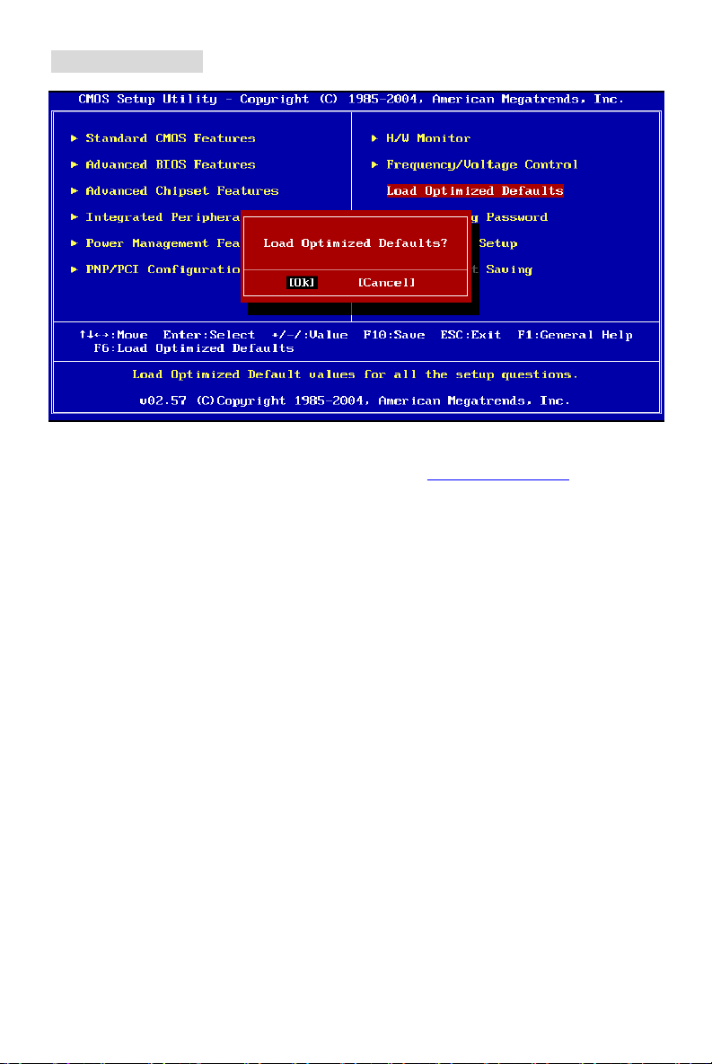
載入 BIOS 預設值
您可以使用此功能載入 BIOS 的出廠(主機板廠商)預設值,以獲得最佳化的系統作業。
若您需要更詳細的 BIOS 介紹與設定,請您至微星科技網站 http://www.msi.com.tw.
73
 Loading...