

MSD Power Grid Power Module 77643, Power Grid Power Module 7764 Installation Instructions Manual
Page 1
INSTALLATION INSTRUCTIONS
1
MSD Power Grid Power Module
PN 7764/77643
ONLINE PRODUCT REGISTRATION: Register your MSD product online. Registering your product
will help in case of a warranty or recall. Go to www.msdperformance.com/registration.
Parts Included:
1-MSD Power Module
1-Main Wiring Harness
1-Mounting Kit
1-MSDView Software
1-USB Cable
1-Loctite 242 packet
Optional: Temperature Sensor PN 2934
WARNING: During installation, disconnect the battery cables. When disconnecting the battery always
remove the Negative cable rst and install it last.
OPERATION
The Power Grid Power Module contains four channels of programmable 20 Ampere solid state relays.
Each output can be controlled independently, or simultaneously, giving great exibility. Each channel
can use Time, Engine Speed, or a Temperature sensor to activate fans, fuel pumps, or NOS systems.
The Power Grid’s data logger within the PN7730 can record all functions of the Power Module.
All four outputs of the Power Module have the identical properties and features.
WIRING
Power Grid
When using the Power Module (PN7764)
with the Power Grid (PN7730), connect
to the Power Grid via the CAN connector.
This increases control options over the
outputs and utilizes the Data Recorder.
Stand Alone
In stand alone mode, a separate pigtail
is offered that will connect to the MSD
CAN-BUS pigtail for the 12V and Ground
required to enable solid state relays.
A Loctite® Threadlocker 242® packet
is included to fasten the threaded screw
for the main power feed.
Apply a small amount of the Loctite
242. It will penetrate the thread grooves,
and bond within 10 minutes. Do not
apply too much Loctite, applying too
much can insulate the wire and cause
problems.
The medium strength bond can be
broken with hand tools, if necessary.
WIRING FEATURES
MAIN HARNESS (16 PIN)
A RED 12GA OUTPUT 1
B RED 20GA INPUT 1
C-F NOT USED
G ORANGE 20GA INPUT 2
H ORANGE 12GA OUTPUT 2
J PINK 12GA OUTPUT 3
K PINK 20GA INPUT 3
L BROWN 20GA TEMP SENSOR
REFERENCE (GROUND)
M WHITE 20GA TEMP SENSOR SIGNAL
N,P NOT USED
R YELLOW 20GA INPUT 4
S YELLOW 12GA OUTPUT 4
CAN CONNECTOR (6 PIN)
1 BLACK 22GA CAN LO
2 YELLOW (SLV) 22GA SHIELD
3 BLACK 18GA GROUND
4 RED 22GA CAN HI
5 RED 18GA POWER (12V)
6 NOT USED
MSD • WWW.MSDPERFORMANCE.COM • (915) 857-5200 • FAX (915) 857-3344
Page 2
2
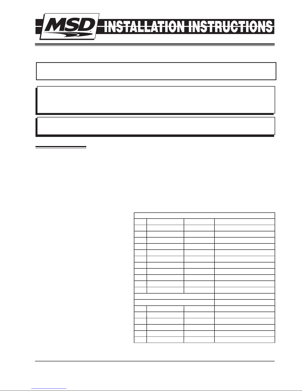
FASTENING SCREW
FOR MAIN POWER FEED
APPLY A SMALL AMOUNT
OF SUPPLIED LOCTITE 242
TO FASTENING SCREW
DISCONNECT
FROM
BATTERY
BEFORE
REMOVING
CAUTION
SEALED
MINI USB &
COVER
CAUTION!
DISCONNECT WIRE
FROM THE BATTERY
BEFORE INSTALLING.
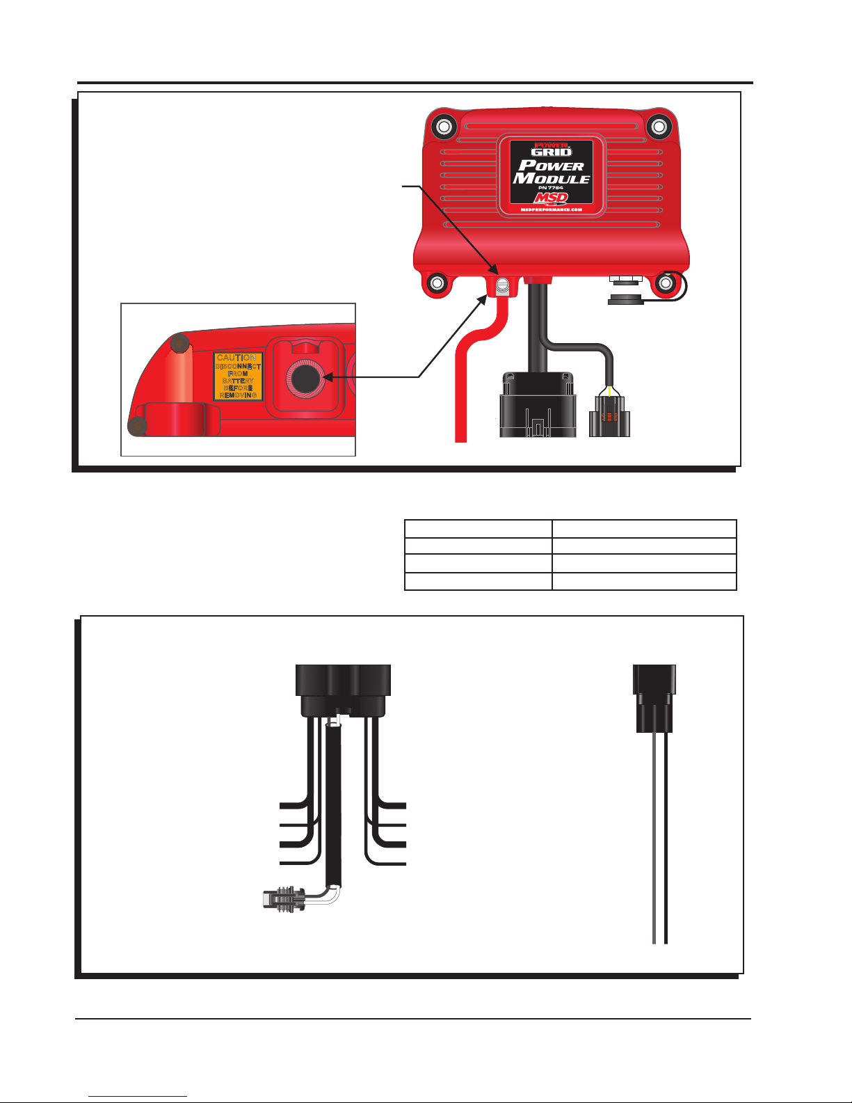
TOTO BATTERY +
BROWN - TEMP SENSOR
REFERENCE (GND) (20GA)
WHITE - SENSOR SIGNAL (20GA)
GROUND
INSTALLATION INSTRUCTIONS
Figure 1 PN 7764 Power Grid Power Module
A power wire must be installed to the Power
Module from the positive Battery Terminal
with an Automotive grade wire rated for heat
and uid resistance.
ORANGE - OUTPUT 2 (12GA)
ORANGE - INPUT 2 (20GA)
PINK - OUTPUT 3 (12GA)
PINK - INPUT 3 (20GA)
WIRE SIZE SELECTION GUIDE
Current Rating AMP Minimum Wire Size AWG
80 4
60 6
20 12
POWER SUPPLIED
WITH CAN PIGTAIL
(WHEN THE POWER GRID
IS NOT USED)
RED - OUTPUT 1 (12GA)
RED - INPUT 1 (20GA)
YELLOW - OUTPUT 4 (12GA)
YELLOW - INPUT 4 (20GA)
ECT
(ENGINE COOLANT
TEMPERATURE SENSOR)
MSD • WWW.MSDPERFORMANCE.COM • (915) 857-5200 • FAX (915) 857-3344
12V
Figure 2 Power Module Harness
Page 3

INSTALLATION INSTRUCTIONS
3
MOUNTING
The Power Module must be mounted in a sturdy, dry location and away from extreme heat. The Power
Module should be mounted using the included rubber mounts to limit excessive vibration. The unit
should not be immersed or subjected to direct spray from a power washer.
MSDVIEW
The MSDView software allows editing of the Output Settings, Timing and Data Acquisition tabs, as
well as turning features on/off and setting up and retrieving data logs.
The following information provides a brief explanation of each function or feature.
While using the software, you can mouse over each item for a brief on-screen explanation. When the
system controller is con nected to a PC via USB, MSDView will automatically recognize it and load
the settings stored in the available modules.
INSTALLATION OF THE MSDVIEW SOFTWARE
1. Insert the installation Flashdrive into available USB port.
2. Locate the ‘autorun.exe’ le on the Flashdrive.
3. Click on “Install MSD View Software”. Click ‘Yes’ when asked ‘Do you want the following program
to make changes to this computer?’.
4. Click ‘Next’ in the ‘Setup - MSD View’ window.
Accept the License Agreement and click ‘Next’.
Choose to accept the desktop icon then click ‘Install’.
Click ‘Finish’ to run application.
5. Connect the Power Module via the USB cable and wait for it to be listed in the product window.
Select the Controller by highlighting the line or checking the box and clicking the ‘View/Hide’ button.
Note: The software may display a prompt window for the latest updates to be installed.
The latest version of the MSDView Software can be downloaded from www.msdperformance.com.
SAVES AND TRANSFERS
Changes to the Power Module via MSDView are made in real time. You can create and save numerous
different setting les to your PC and load them back into the unit for different applications.
The following will go through a general description of the software for the Power Grid Power Module
PN 7764 Controller.
OPERATION
The 7764 Power Grid Power Module is a fully programmable 4-channel solid state relay. The use
of the Power Module eliminates electromechanical relays and fuses. Any of the four outputs can
be congured as a digital output (i.e ON/OFF) or can be congured as a Pulse Width Modulated
output (i.e. PWM) with user-programmable frequencies up to 10 Kilohertz. The solid state switches
are protected from over-current and over-temperature conditions and can handle currents up to 20
Amperes continuously. The user has the ability to program a lower current limit.
Any of the four input wires or the signal from an external temperature sensor can be used to control
any one of the outputs. Moreover, the Power Module can be used in conjunction with the Power Grid
(PN7730) to expand its programmable options. For instance, when connected to the Power Grid, the
outputs can be controlled by the launch wire signal or as a function of engine speed (RPM).
All the programmable features are congured using the MSDView software provided.
The Power Module has two modes of operation: When the CAN bus is functional, it will operate in
POWER-GRID mode. Otherwise it will operate in STAND-ALONE mode.
Note: The Power Module self detects the mode of operation by the way it is connected in the circuit.
STAND-ALONE
The user can control any of the four outputs independently using any of the four input wires or the
MSD • WWW.MSDPERFORMANCE.COM • (915) 857-5200 • FAX (915) 857-3344
Page 4

4
INSTALLATION INSTRUCTIONS
temperature reading from an external temperature sensor. Also, the selected input wire can be used
to trigger a time counter, like a launch wire, and control the time of activation as well as the duration
of the output. The state of the inputs and outputs can be observed in the monitor window in real time.
POWER GRID MODE
The Power module is connected to the Power Grid (PN7730) via the CAN connector.
In Power-Grid mode, the Power Module retains all the features available in Stand-Alone mode and
expands the control and programmable features. In addition to the four input wires, the user can
select the “launch wire” signal from the Power Grid as the activation source. Also, the output control
can be enabled/disabled based on the engine speed (RPM) reading from the Power Grid.
In addition to providing expanded control over the outputs, Power Grid Mode utilizes the Power Grid
data recorder.
Another feature the Power Grid adds to the Power Module is the ability to control ignition timing retard
as a function of “Time From Activation”. Time from activation is the time elapsed since the activation
of the selected Power Module input wire. A 2-D plot of “timing retard vs time from activation” is
provided for this feature.
Note: For more information on the features and settings, please refer to the “SETTINGS” section below.
PROGRAMMABLE FEATURES
OUTPUT SETTINGS
These settings allows control over the behavior of each output. Each one of the four outputs has an
“OUTPUT SETTINGS” sub-tab and is congured independently.
SETTINGS
Features, such as the frequency, current limit and activation source, can be congured under this tab.
Frequency: Signal frequency of the Solid state relay output in PWM mode only.
Current Limit: When the solid state output current exceeds the set value, the output will turn OFF until
the next turn-on command. Note: Continuous load current over 20 Amps may overheat the
driver that consequently will turn OFF to protect itself.
Temperature Control: Sets the method that the external temperature sensor controls the
corresponding output of the solid state relay.
Disable: The temperature sensor signal does not affect the output.
ON/OFF: The output will be ON when the sensor temperature is above the value in the
“Temperature Setting” or OFF when the sensor temperature is below it. If “AC Input” is used
, the AC is ON the output will be ON irrespective of the sensor temperature.
PWM: The output will have a varying duty cycle between 50 and 100%, or 0% to control the
temperature until it reaches the desired value. A value of 0% is valid only if “AC Input is OFF
or not used. Otherwise, the minimum value is 50% duty cycle.
Temperature Setting: The output state will change to maintain the value set here. For example
in “ON/OFF” mode the output will be ON when the measured sensor temperature is above
this setting and the output will turn OFF when the sensor temperature is below this setting.
Note: when the “AC Input” is ON, the output will be ON regardless of the temperature.
AC Input: Selects the wire that will indicate AC ON. When the AC is ON the output will be at
least 50% ON in PWM mode or fully ON in ON/OFF mode. The “AC Input” setting is available
only in “Temperature Control” mode.
Wire Activation Source 1 - 4,: Determines which of the inputs must activate for the output to be ON.
All non-disabled inputs except the Launch must be ON for the output to be ON. If the Launch
is selected, the Launch mode must be OFF for the output to be ON.
Note: The inputs selected act as an AND function. Meaning: All the dened inputs must be ON at
the same time to enable the output wire
Timer During Wire Disable: Determines the status of the Channel’s Timer while the output is
MSD • WWW.MSDPERFORMANCE.COM • (915) 857-5200 • FAX (915) 857-3344
Page 5

INSTALLATION INSTRUCTIONS
5
disabled by one of the wires. This setting is available only if “Launch” is selected as the ”Wire
Activation Source 1”. The timer of every output will reset to 0 during launch mode if “Launch”
is used as a condition for activation.
Possible options:
Continue: Timer will continue to increment even when the output is disabled due to
one of the wires.
Pause: Timer will pause, or “freeze”, when the output is disabled due to one of the wires.
Restart: Timer will clear, or become 0, when the output is disabled due to one of the
wires.
Note: Launch mode can be selected as the activation source only in "Wire Activation Source 1" and
if the Power Module is in Power Grid Mode.
Time Setting: Determines if the output will be controlled directly by the “Activation Source” or by the
“Time from Activation”.
Possible options:
ON/OFF: The output relay is directly controlled by the activation wires.
Time Setting: The output will become active (ON) when the time from activation
exceeds the “Activation Time” value and will stay active for the number of seconds
specied in the “Activation Duration” setting. Note: Activation Duration value of '0'
means: indenite.
Graph: The output will activate at a duty cycle set in the corresponding graph.
RPM Setting: Enables or disables the use of Engine Speed (RPM) as a condition for activating the
output. The “RPM Setting” is available only in Power Grid mode.
Activation: Allows the output to become active only when the Engine Speed exceeds this setting.
Deactivation: When set above the “Activation” speed, the output will deactivate when the engine
speed is above the “Deactivation” speed (Window control). Alternatively, when the
“Deactivation” is set below the “Activation”, the output will deactivate when the engine speed
drops below the “Deactivation” speed (Hysteresis).
Note: Each output within the Power Module can activate engine timing retard similar to the step retard
within the Power Grid. Therefore, with the use of the Power Module there are effectively, up
to four additional Step Retard inputs. The retard functionality timers are tied to the status of
the solid state relay.
Total Retard: The maximum ignition timing to be removed from the engine when the output is activated.
Minimum Engine RPM: The minimum engine speed that must be met to enable the total retard.
Note: The timing retard here is controlled by the state of the output relay
ON Ramp Time: The time it takes to reach the full “Total Retard”. For example, with 10 degrees
of “Total Retard” and 1 second “Ramp Time”, the controller will retard 1 degree every 0.1
seconds until the full 10 degrees of timing has been pulled out. This timer will start only after
the “Minimum Engine RPM” condition is achieved.
OFF Delay: The time the “Total Retard” remains in effect after the output turns completely OFF (or
0% duty cycle).
OFF Ramp Time: The time it takes to decay the “Total Retard”, ramping timing back into the motor
RPM Setting: This setting enables/disables the ability to control the output as a function of engine
speed (RPM).
Activation: The output activates when the engine speed exceeds this value.
Deactivation: When set above the “Activation” speed, the output will deactivate when the
engine speed is above the “Deactivation” speed. On the other hand, when the “Deactivation”
is set below the “Activation”, the output will deactivate when the engine speed drops below
the “Deactivation” speed.
Note: “Total Retard” and “RPM Setting” are only available in Power Grid Mode (i.e. when the Power
module is connected to a Power Grid PN7730).
DUTY CYCLE
This plot controls the output duty cycle as a function of “Time From Activation”. Note: This plot is
functional only when the “Time Setting” is set to “Graph”.
MSD • WWW.MSDPERFORMANCE.COM • (915) 857-5200 • FAX (915) 857-3344
Page 6

6
INSTALLATION INSTRUCTIONS
TIMING
This plot controls the amount of timing retard applied to the engine as a function of “Time From
Activation”.
Note: This timing is only available in Power Grid Mode (i.e. when the Power module is connected to
a Power Grid PN7730).
DATA ACQUISITION
The data acquisition system works in conjunction with the Power Grid (PN7730) data recorder. It allows
the user to record input activations as well as the state of any of the outputs and temperature
The 'Temperature Setting' and
'AC Input' features will be enabled
when 'ON/OFF' or 'PWM' are
selected.
The 'Timer During Wiring Disable'
setting will show when 'Launch' is
selected
Figure 3 Settings.
Figure 4 Output Duty Cycle vs Time From Activation.
MSD • WWW.MSDPERFORMANCE.COM • (915) 857-5200 • FAX (915) 857-3344
Page 7

INSTALLATION INSTRUCTIONS
7
sensor while going down the track. When connected to the Power Grid, the Power Module
sends the enabled channels over the CAN bus to be recorded by the Power Grid. The channels
will be recorded at a rate of 5 samples per second.
Figure 5 Timing Retard vs Time From Activation
MONITORS
MONITOR DESCRIPTION
Engine RPM* Engine speed (RPM) received from PN7730
Ignition Timing* Ignition timing referenced to Top Dead Center (TDC) received from
PN7730
Timing Retard* Total retard currently applied
Temperature External temperature sensor reading
Time From Activation* Time from release of the activation source
Ignition Voltage Voltage supplied on the ignition wire
1-Red Input Input 1 (Red) status (ON or OFF)
1-Red Output Duty Cycle Output 1 (Red) duty cycle. When selected as a digital output,
ON is 100% and OFF is 0%
2-Orange Input Input 2 (Orange) status (ON or OFF)
2-Orange Output Duty Cycle Output 2 (Orange) duty cycle. When selected as a digital output,
ON is 100% and OFF is 0%
3-Pink Input Input 3 (Pink) status (ON or OFF)
3-Pink Output Duty Cycle Output 3 (Pink) duty cycle. When selected as a digital output,
ON is 100% and OFF is 0%
4-Yellow Input Input 4 (Yellow) status (ON or OFF)
4-Yellow Output Duty Cycle Output 4 (Yellow) duty cycle. When selected as a digital output,
ON is 100% and OFF is 0%
* This monitor is only available in Power Grid mode
MSD • WWW.MSDPERFORMANCE.COM • (915) 857-5200 • FAX (915) 857-3344
Page 8

8 INSTALLATION
8
INSTALLATION INSTRUCTIONS
CHANNELS
CHANNEL DESCRIPTION
1-Red Input Input 1 (Red) status (ON or OFF)
1-Red Output Output 1 (Red) duty cycle. When selected as a digital output, ON is
100% and OFF is 0%
2-Orange Input Input 2 (Orange) status (ON or OFF)
2-Orange Output Output 2 (Orange) duty cycle. When selected as a digital output,
ON is 100% and OFF is 0%
3-Pink Input Input 3 (Pink) status (ON or OFF)
3-Pink Output Output 3 (Pink) duty cycle. When selected as a digital output, ON
is 100% and OFF is 0%
4-Yellow Input Input 4 (Yellow) status (ON or OFF)
4-Yellow Output Output 4 (Yellow) duty cycle. When selected as a digital output, ON
is 100% and OFF is 0%
Temperature External temperature sensor reading
ALERTS
ALERT DESCRIPTION
Over current Output 1 Output 1 was disabled because the output current exceeded the set limit
Over current Output 2 Output 2 was disabled because the output current exceeded the set limit
Over current Output 3 Output 3 was disabled because the output current exceeded the set limit
Over current Output 4 Output 4 was disabled because the output current exceeded the set limit
EEPROM write error Error writing to EEPROM
EEPROM CRC error EEPROM data corrupted
Service
In case of malfunction, this MSD component will be repaired free of charge according to the terms of the warranty.
When returning MSD components for warranty service, Proof of Purchase must be supplied for verication. After
the warranty period has expired, repair service is based on a minimum and maximum fee.
All returns must have a Return Material Authorization (RMA) number issued to them before
being returned. To obtain an RMA number please contact MSD Customer Service at 1 (888) MSD-7859 or visit
our website at www.msdperformance.com/rma to automatically obtain a number and shipping information.
When returning the unit for repair, leave all wires at the length in which you have them installed. Be sure to include
a detailed account of any problems experienced, and what components and accessories are installed on the vehicle.
The repaired unit will be returned as soon as possible using Ground shipping methods (ground shipping is covered
by warranty). For more information, call MSD at (915) 855-7123. MSD technicians are available from 7:00 a.m. to
5:00 p.m. Monday - Friday (mountain time).
Limited Warranty
M
SD warrants this product to be free from defects in material and workmanship under its intended normal use*,
when properly installed and purchased from an authorized MSD dealer, for a period of one year from the date of
the original purchase. This warranty is void for any products purchased through auction websites. If found to be
defective as mentioned above, it will be repaired or replaced at the option of MSD. Any item that is covered under
this warranty will be returned free of charge using Ground shipping methods.
This shall constitute the sole remedy of the purchaser and the sole liability of MSD. To the extent permitted by
law, the foregoing is exclusive and in lieu of all other warranties or representation whether expressed or implied,
including any implied warranty of merchantability or tness. In no event shall MSD or its suppliers be liable for special
or consequential damages.
*Intended normal use means that this item is being used as was originally intended and for the original application
as sold by MSD. Any modications to this item or if it is used on an application other than what MSD markets the
product, the warranty will be void. It is the sole responsibility of the customer to determine that this item will work
for the application they are intending. MSD will accept no liability for custom applications.
MSD • WWW.MSDPERFORMANCE.COM • (915) 857-5200 • FAX (915) 857-3344
FRM 32531 Revised 02/18
© 2016 MSD LLC
 Loading...