

Page 1
MSD-8 Plus Ignition
PN 7805
ONLINE PRODUCT REGISTRATION: Register your MSD product online and you’ll be entered
in our monthly 8.5mm Super Conductor Spark Plug Wire give-away! Registering your product
will help if there is ever a warranty issue with your product and helps the MSD R&D team create
new products that you ask for! Go to www.msdperformance.com/registration.
Note: Solid Core spark plug wires cannot be used with an MSD Ignition.
Parts Included:
1 - MSD-8 Plus Ignition
1 - Mag Pickup Extension Harness, PN 8860
4 - Vibration Mounts and Hardware
4 - RPM Modules: 3K, 7K, 8K and 9K
WARNING: Before installing the MSD Distributor, disconnect the battery cables. When disconnecting
the battery cables, always remove the Negative (-) cable first and install it last.
1 - PN 8830 Filter
1 - Coil Harness
1 - Power Harness
1 - Parts Bag, Mounts, Terminals, etc.
FEATURES
SINGLE OR DUAL COIL OUTPUT
The MSD-8 Plus Ignition Control is intended for racing use only. The Ignition has the ability to be
used with single or dual coil systems. Note that when using a single coil, both coil positive wires must
be connected to the coil.
RPM LIMITERS
The MSD-8 Plus Ignition is equipped with a 2-Step Rev Control. The Ignition will accept two rpm
modules so two different rev limits can be set. One rev limit can be used for over-rev protection while
the second limit can be activated on the starting line for a lower rpm limit to assist in staging and for
consistent holeshots. When 12 volts are applied
to the 2-Step terminal (2’S’), Module 1 is active.
Module 2 is active when there is no 12 volts.
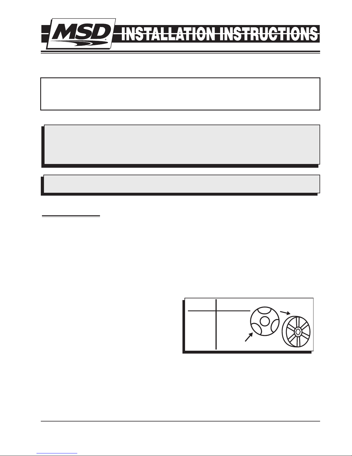
CYLINDER SELECT
This ignition can be used on 2, 4, 6 (even-fire)
or 8-cylinder engines. The ignition is set for
8-cylinder operation. To program the unit for
other engines, remove the one screw that holds
the cover to reveal three wire loops (Figure
1). Cutting a wire loop determines the cylinder
selection.
Cylinders Loops to Cut
8 None
6 One
4 Two
2 Three
Figure 1 Cylinder Programming.
Cut loops
Remove cap
SPARK LED
When the coil fires, current is sensed and this LED will flash. These LEDs confirm that the ignition
has received a trigger signal and that the ignition is working properly. Each time a coil fires, current
is sensed and the corresponding LED will flash. (If the coil is not connected, the LED will not flash.)
When the engine is running, it will appear solid.
M S D • W W W . M S D P E R F O R M A N C E . C O M • ( 9 1 5 ) 8 5 7 - 5 2 0 0 • F A X ( 9 1 5 ) 8 5 7 - 3 3 4 4
Page 2
2 INST A L L A TION I N S TRUCT I O N S
GENERAL INFORMATION
BATTERY
An MSD-8 Plus Ignition Control will operate on any negative ground, 12 volt electrical system with a
distributor. The MSD can be used with 16 volt batteries and can withstand a momentary 24 volts in
case of jump starts. The Ignitions will deliver full voltage with a supply of 10-18 volts.
If your application does not use an alternator, allow at least 30 amp/hour for every half hour of
operation. If the engine is cranked with the same battery or other accessories such as an electric fuel
or water pump, the amp/hour rating should be higher.
COILS
The MSD-8 Plus Ignition must be used with an MSD Pro Power Series Coil. The Pro Power HVC, PN
8251, Pro Power HVC II, PN 8261 or for short duration racing, the PN 8201 Pro Power Coil. If you
have any questions concerning coils, contact our Customer Service Department at (915) 855-7123.
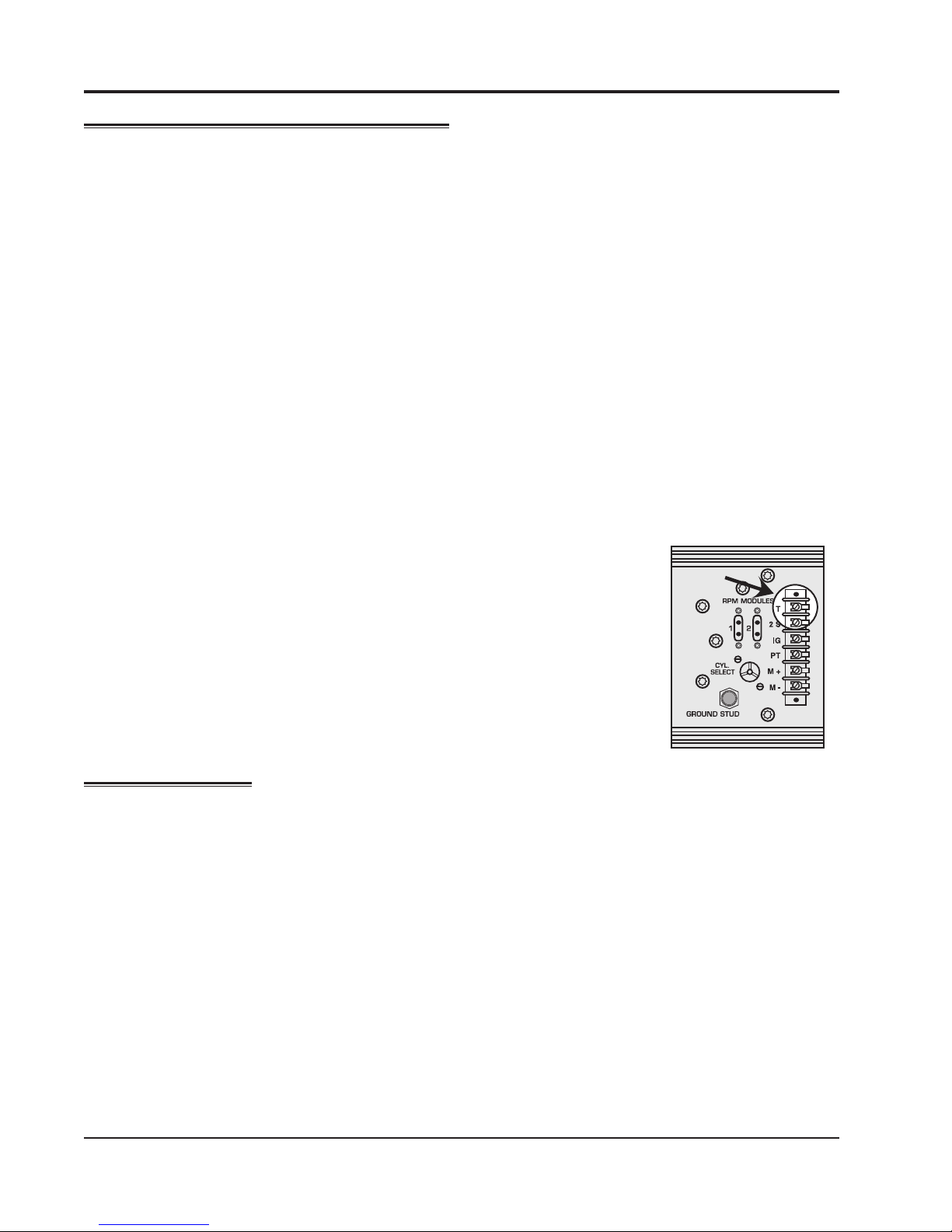
TACHOMETERS
The MSD Ignition features a Tach Output Terminal on the terminal strip. This terminal provides a
trigger signal for tachometers, a shift light or other add-on rpm activated devices. The Tach Output
Terminal produces a 12 volt square wave signal with a 20% duty cycle.
SPARK PLUGS AND WIRES
Spark plug wires are very important to the operation of your ignition system. A good quality, helically
wound wire and proper routing are required to get the best performance
from your ignition, such as the MSD Heli-Core or 8.5mm Super Conductor.
TACH
Note: Solid Core spark plug wires cannot be used with an MSD Ignition.
TERMINAL
A helically, or spiral wound wire must be used. This style wire provides
a good path for the spark to follow while keeping Electro Magnetic
Interference (EMI) to a minimum. Excessive EMI, such as the amount that
solid core wires produce, will interfere with the operation of the MSD and
other electronics on your car.
MOUNTING
Figure 2 Tach Terminal.
The MSD can be mounted in most positions. It can be mounted in the engine compartment as long
as it is away from direct engine heat sources. It is not recommended to mount the unit in an enclosed
area such as the glovebox.
When you find a suitable location to mount the unit, make sure the wires of the ignition reach their
connections. Hold the Ignition in place and mark the location of the mounting holes. Use a 1/4” drill
bit to drill the holes. Install the vibration mounts to the ignition and mount the unit.
M S D • W W W . M S D P E R F O R M A N C E . C O M • ( 9 1 5 ) 8 5 7 - 5 2 0 0 • F A X ( 9 1 5 ) 8 5 7 - 3 3 4 4
Page 3
INST A L L A TION I N S TRUCT I O N S 3
Terminal Wire
Function
ORANGE
Connects to the positive (+) terminal of the second coil.This is the only
wire that makes electrical contact with the coil positive terminal.
COIL 2 +
BLACK
Connects to the negative (-) terminal of the second coil. This is the only
wire that makes electrical contact with the coil negative terminal.
COIL 2-
HEAVY
BLACK
This wire connects to a good ground, either at the battery negative (-) terminal
or to the engine.
BAT -
HEAVY
RED
GRAY
BAT +
TACHTACH
2-STEP
IGNITION
Connects to a switched 12 volt source. Such as the ignition key or switch.
RED
WHITE
This wire is used to connect to the points, electronic ignition amplifier output
or to the Yellow wire of an MSD Timing Accessory. When this wire is used,
the Magnetic Pickup connector is not used.
POINTS
VIOLETMAG +
GREENMAG -
DARK
BLUE
This wire connects directly to the battery positive (+) terminal or to a positive
battery junction or the positive side of the starter solenoid. Note: Never
connect to the alternator.
This terminal delivers a 12 volt square wave signal as an output for a
tachometer or devices that require an rpm signal.
When this terminal is connected to 12 volts, RPM module 1 is active. When
there is no 12 volts, RPM module 2 is active.
These wires are routed together in one harness from the Magnetic Pickup
connector. The connector plugs directly into an MSD Distributor or Crank
Trigger. It will also connect to factory magnetic pickups or other aftermarket
pickups (Figure 4). The Violet wire is pos. (+) and the Green is neg. (-).
When these wires are used, the Points Terminal is not.
ORANGECOIL 1 +
BLACKCOIL 1-
Connects to the positive (+) terminal of the coil.This is the only wire that
makes electrical contact with the coil positive terminal.
Connects to the negative (-) terminal of the coil. This is the only wire that
makes electrical contact with the coil negative terminal.
WIRING
GENERAL WIRING INFORMATION
Wire Length: All of the wires of the MSD Ignition may be shortened as
long as quality connectors are used or soldered in place. To lengthen the
wires, use one size bigger gauge wire (10 gauge for the power leads and
16 gauge for the other wires) with the proper connections. All connections
must be soldered and sealed.
Grounds: A poor ground connection can cause many frustrating problems.
When a wire is specified to go to ground, it should be connected to the
battery negative terminal, engine block or chassis. There should always
be a ground strap between the engine and the chassis. Always securely
connect the ground wire to a clean, paint free metal surface.
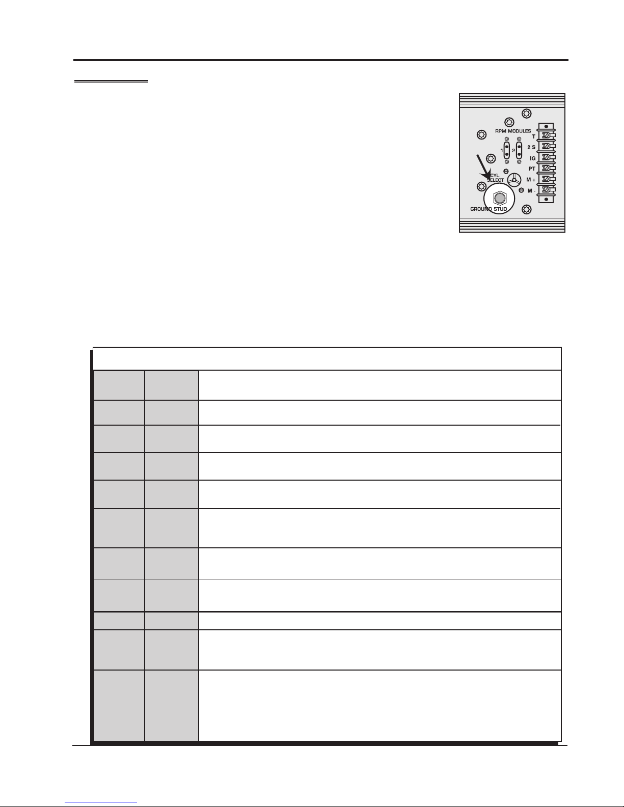
The MSD-8 Plus has a ground stud just to the left of the terminal strip. Use this to ground other MSD
accessories (Figure 3).
Coil Connections: When using a single coil, both coil positive terminals must be connected to the
coil. Either connect both orange wires to the coil, or use the supplied jumper to connect the two coil
positive termianls at the terminal strip.
GROUND
Figure 3 Ground Stud.
M S D • W W W . M S D P E R F O R M A N C E . C O M • ( 9 1 5 ) 8 5 7 - 5 2 0 0 • F A X ( 9 1 5 ) 8 5 7 - 3 3 4 4
Page 4

4 INST A L L A TION I N S TRUCT I O N S
ROUTING WIRES
The MSD wires should be routed away from direct heat sources such as exhaust manifolds and
headers and any sharp edges. The trigger wires should be routed separate from the other wires
and spark plug wires. It is best if they are routed along a ground plane such as the block or firewall
which creates an electrical shield. The magnetic pickup wires should always be routed separately
and should be twisted together to help reduce extraneous interference (the harness supplied is
already twisted).
The chart shows the polarity of other common magnetic pickups. If using a different magnetic pickup,
use the MSD 2-Pin connector, available as PN 8824, for a direct plug-in installation.
WARNING: The MSD-8-Series Ignitions are capacitive
discharge ignitions. High voltage is present
at the coil primary terminals. Do not touch
the coil or connect test equipment to the
terminals.
PRESTART CHECK LIST
• The only wires connected to the coil terminals are the MSD
Common Mag Pickup Wires
Distributor Colors
Mag+ MagMSD Org/Blk Vio/Blk
MSD Crank Trigger Org/Blk Vio/Blk
Ford Orange Purple
46/48000
Accel
Accel
Chrysler Org/Wht Black
Mallory Org/Blk Vio/Blk
Series Org/Blk Vio/Blk
51/61000
Series Red Black
Orange to coil positive and Black to coil negative.
• The small Red wire of the MSD is connected to a switched
Figure 4 Common Mag Pickup Wires.
12 volt source.
• The MSD power leads are connected directly to the battery positive and negative terminals.
• The battery is connected and fully charged if not using an alternator.
• The engine is equipped with at least one ground strap to the chassis.
TROUBLESHOOTING
Every MSD Ignition undergoes numerous quality control checks including a four hour burn-in test.
If you experience a problem with your MSD, our research has shown that the majority of problems
are due to improper installation or poor connections.
The Troubleshooting section has several checks and tests you can perform to ensure proper
installation and operation of the MSD. If you have any questions concerning your MSD, call our
Customer Support Department at (915) 855-7123, 7 - 6 mountain time.
MISSES AND INTERMITTENT PROBLEMS
Experience at the races has shown that if your engine is experiencing a miss or hesitation at higher
rpm, it is usually not directly ignition related. Most probable causes include a coil or plug wire
failure, arcing from the cap or boot plug to ground or spark ionization inside the cap. Several items
to inspect are:
• Always inspect the plug wires at the cap and at the plug for a tight connection and visually
inspect for cuts, abrasions or burns.
• Inspect the Primary Coil Wire connections. Because the MSD is a Capacitive Discharge
ignition and it receives a direct 12 volt source from the battery, there will not be any
voltage at the Coil Positive (+) terminal even with the key turned On. During cranking
or while the engine is running, very high voltage will be present and no test equipment
should be connected.
• Make sure that the battery is fully charged and the connections are clean and tight. If you
are not running an alternator this is an imperative check. If the battery voltage falls below
10 volts during a race, the MSD output voltage will drop.
M S D • W W W . M S D P E R F O R M A N C E . C O M • ( 9 1 5 ) 8 5 7 - 5 2 0 0 • F A X ( 9 1 5 ) 8 5 7 - 3 3 4 4
Page 5

INST A L L A TION I N S TRUCT I O N S 5
GRE EN
JUM PER
WIRE
VI OLET
MAGNETIC PICKUP TRIGGER
WHITE WIRE TRIG G E R
WARNING: Do not touch the coil terminals during cranking or while the engine is running.
• Is the engine running lean or excessively rich? Inspect the spark plugs and fuel system.
• Inspect all wiring connections for corrosion or damage. Remember to always use proper
connections followed by soldering and seal the connections completely.
LED: The LED on the ignition will assist in troubleshooting. If the LED does not flash, there is
no current through the primary coil wires. This could be due to poor connections at the
coil, the coil itself or the ignition. Once you confirm that the trigger signal is working, try a
different coil. See below to test for spark.
If everything checks positive, use the following procedure to test for spark. MSD also offers an
Ignition Tester, PN 8998. This tool allows you to check your complete ignition system while it is in
the car as well as the operation of rpm limits, activated switches and shift lights.
CHECKING FOR SPARK
If triggering the ignition with the White wire:
1. Make sure the ignition switch is in the “Off” position.
2. Remove the coil wire from the distributor cap and set
the terminal approximately 1/2” from ground.
3. Disconnect the MSD White wire from the distributor’s
points or ignition amplifier.
4. Turn the ignition to the "On" position. Do not crank
the engine.
5. Rapidly tap the White wire to ground several times
(the first 3-4 times will not spark). When the wire is
pulled from ground, a spark should jump from the
coil wire to ground. If spark is present, the ignition is
working properly. If there is no spark skip to step 6
on page 6:
Figure 5 Checking for Spark with a White Wire.
If triggering with the Magnetic Pickup:
1. Make sure the ignition switch is in the “Off” position.
2. Remove the coil wire from the distributor cap and
set the terminal approximately 1/2” from ground.
3. Disconnect the MSD magnetic pickup wires from
the distributor.
4. Turn the ignition to the "On" position. Do not crank
the engine.
5. With a small jumper wire, short the MSD’s Green
and Violet magnetic pickup wires together several
times (the first 3-4 times will not spark). Each time you break this ground (rapidly), a spark
should jump from the coil wire to ground. If spark is present, the ignition is working properly. If
there is no spark skip to step 6 on page 6.
M S D • W W W . M S D P E R F O R M A N C E . C O M • ( 9 1 5 ) 8 5 7 - 5 2 0 0 • F A X ( 9 1 5 ) 8 5 7 - 3 3 4 4
Figure 6 Checking for Spark with Magnetic Pickup.
Page 6

6 INST A L L A TION I N S TRUCT I O N S
6. If there is no spark:
A. Inspect all of the wiring.
B. Substitute another coil and repeat the test. If there is now spark, the coil is at fault.
C. If there is still no spark, check to make sure there is 12 volts on the small Red wire from the
MSD when the key is in the "On" position. If 12 volts is not present, find another switched 12 volt
source and repeat the test.
D. If, after following the test procedures and inspecting all of the wiring, there is still no spark, the
MSD Ignition is in need of repair. See the Warranty and Service section for information.
If there is no spark, but the LED flashes, check for a coil problem.
The following wiring diagrams illustrate numerous installations on different vehicles and applications.
If you experience difficulties when installing your MSD, contact our Customer Support Department at
(915) 855-7123 (7 - 6 Mountain time) or e-mail us at: msdtech@msdignition.com
COIL TERMINALS
MSD supplies heavy duty, nickel plated terminals for the
connections. There is also a piece of heat-shrink sleeve to
cover the wire crimp.
MSD SYSTEMS Installing to an MSD Distributor/Crank Trigger.
BLACK
ORANGE
COIL 1-
COIL 1+
COIL 2+
COIL 2-
SUPPLIED JUMPER*
GRAY
BLUE
HEAVY RED TO BATTERY POSITIVE
HEAVY BLACK TO BATTERY NEGATIVE
TO CHASSIS
*NOTE: WHEN USING A SINGLE COIL, BOTH COIL POSITIVE
TERMINALS MUST BE CONNECTED TO THE COIL.
EITHER CONNECT BOTH ORANGE WIRES TO THE COIL,
OR USE THE SUPPLIED JUMPER TO CONNECT THE
COIL POSITIVE TERMIANLS AT THE TERMINAL STRIP.
TO 12 VOLTS
TO SWITCHED
12 VOLTS
M S D • W W W . M S D P E R F O R M A N C E . C O M • ( 9 1 5 ) 8 5 7 - 5 2 0 0 • F A X ( 9 1 5 ) 8 5 7 - 3 3 4 4
Page 7

INST A L L A TION I N S TRUCT I O N S 7
MSD SYSTEMS Single coil with an MSD Timing Control.
PN 8261
BLACK
ORANGE
COIL 1-
COIL 1+
COIL 2+
COIL 2-
SUPPLIED JUMPER*
SUPPIED JUMPER
HEAVY RED TO
BATTERY POSITIVE
HEAVY BLACK TO
BATTERY NEGATIVE
GRAY
TO CHASSIS
MSD SYSTEMS With an MSD Timing Control.
PN 8261
BLUE
TO SWITCHED
12 VOLTS
*NOTE: WHEN USING A SINGLE COIL, BOTH COIL POSITIVE
TERMINALS MUST BE CONNECTED TO THE COIL.
EITHER CONNECT BOTH ORANGE WIRES TO THE COIL,
OR USE THE SUPPLIED JUMPER TO CONNECT THE
COIL POSITIVE TERMIANLS AT THE TERMINAL STRIP.
PN 8261
BLACK
ORANGE
COIL 1-
COIL 1+
COIL 2+
COIL 2-
BLACK
ORANGE
GRAY
HEAVY RED TO
BATTERY POSITIVE
HEAVY BLACK TO
BATTERY NEGATIVE
TO CHASSIS
BLUE
TO SWITCHED
12 VOLTS
M S D • W W W . M S D P E R F O R M A N C E . C O M • ( 9 1 5 ) 8 5 7 - 5 2 0 0 • F A X ( 9 1 5 ) 8 5 7 - 3 3 4 4
Page 8

MSD SYSTEM Installing to a Programmable Digital 7, PN 7531
THE MSD-8 PLUS CAN BE USED IN TANDEM WITH A
PROGRAMMABLE 7-PLUS. THIS SYSTEM DELIVERS THE
POWER OF THE MSD-8 WITH THE ADVANCED PC TUNING
CAPABILITIES OF THE PN 7531 IGNITION.
Gray
Plugs into number
2 module only
HEAVY BLACK TO BATTERY
Programmable
R
DIGITAL-7 PLUS
TO APM
SENSOR
3 N PI
C B A
TDA A
U P TO T U
NOTE:
Change following in ProdataTest Spark ON => Test Spark OFF
CylCnt Tach Trigger => Tach Timing
RevMax OutCam => OutRev
Gray
Pink - Step 1 Retard/Gear 2
Violet - Step 2 Retard/Gear 3
Tan - Step 3 Retard/Gear 4
Red - To switched 12 volts
White - Amplifier Trigger
Yellow - Shift Light
Brown/White - RPM/Time/PSI Switch
Dark Blue -
Light Blue -
LT BLUE
GREEN
VIOLET
GREEN
TO CAM SYNC
PICKUP
PN 8860
HARNESS
Launch Rev Limit to Line Lock or Clutch Switch
Reset for Shift Light, Gear Indicator, Launch Ramp,
Gear Curve, Disables Slew when Activated.
Burnout Rev Limit overrides other rev limits,
Disables Launch History and Slew Rev Limit
(Wire to outside source to be switched by crew.)
VIOLET
GREEN
Service
In case of malfunction, this MSD component will be repaired free of charge according to the terms of the warranty.
When returning MSD components for warranty service, Proof of Purchase must be supplied for verification. After
the warranty period has expired, repair service is based on a minimum and maximum fee.
All returns must have a Return Material Authorization (RMA) number issued to them before
being returned. To obtain an RMA number please contact MSD Customer Service at 1 (888) MSD-7859 or visit
our website at www.msdperformance.com/rma to automatically obtain a number and shipping information.
When returning the unit for repair, leave all wires at the length in which you have them installed. Be sure to include
a detailed account of any problems experienced, and what components and accessories are installed on the vehicle.
The repaired unit will be returned as soon as possible using Ground shipping methods (ground shipping is covered
by warranty). For more information, call MSD at (915) 855-7123. MSD technicians are available from 7:00 a.m. to
5:00 p.m. Monday - Friday (mountain time).
Limited Warranty
M
SD warrants this product to be free from defects in material and workmanship under its intended normal use*,
when properly installed and purchased from an authorized MSD dealer, for a period of one year from the date of
the original purchase. This warranty is void for any products purchased through auction websites. If found to be
defective as mentioned above, it will be repaired or replaced at the option of MSD. Any item that is covered under
this warranty will be returned free of charge using Ground shipping methods.
This shall constitute the sole remedy of the purchaser and the sole liability of MSD. To the extent permitted by
law, the foregoing is exclusive and in lieu of all other warranties or representation whether expressed or implied,
including any implied warranty of merchantability or fitness. In no event shall MSD or its suppliers be liable for special
or consequential damages.
*Intended normal use means that this item is being used as was originally intended and for the original application
as sold by MSD. Any modifications to this item or if it is used on an application other than what MSD markets the
product, the warranty will be void. It is the sole responsibility of the customer to determine that this item will work for
the application they are intending. MSD will accept no liability for custom applications.
M S D • W W W . M S D P E R F O R M A N C E . C O M • ( 9 1 5 ) 8 5 7 - 5 2 0 0 • F A X ( 9 1 5 ) 8 5 7 - 3 3 4 4
FRM29363 Revised 04/12 Printed in U.S.A.
© 2012 Autotr onic Con trols Cor poration
 Loading...