

Page 1
Flying Magnet Crank Trigger Kit
General Wiring
ONLINE PRODUCT REGISTRATION: Register your MSD product online and you’ll be entered
in our monthly 8.5mm Super Conductor Spark Plug Wire give-away! Registering your product
will help if there is ever a warranty issue with your product and helps the MSD R&D team create
new products that you ask for! Go to www.msdperformance.com/registration.
These instructions cover the wiring and general installation tips of all the MSD Flying Magnet Crank
Trigger Kits. For installation of the brackets and trigger wheel refer to the enclosed Installation
Instructions for each specific kit.
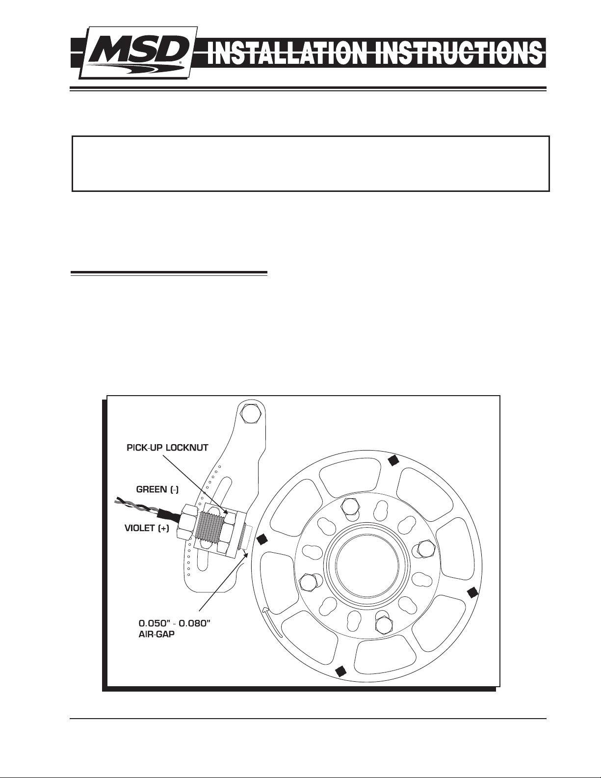
SETTING THE AIR-GAP
The air-gap between the trigger wheel and the non-magnetic pickup is important to the operation of
the crank trigger system, however its adjustment does not affect engine power or performance. The
proper air-gap will result in a good trigger signal at cranking rpm through high rpm with no interference
to the wheel. The optimum setting is generally between 0.050" – 0.080".
With the brackets and trigger wheel mounted (with the arrow on the wheel facing out) position the
pickup within 0.050" – 0.080" from the wheel then tighten the locknut (Figure 1). Do not over tighten
the locknut.
Figure 1 Setting the Air-Gap.
M S D • W W W . M S D P ER F O R M A N C E . C O M • ( 9 1 5) 8 5 7 - 5 2 0 0 • F A X ( 91 5 ) 8 57 - 3 3 4 4
Page 2
2
INSTALLATION INSTRUCTIONS
WIRING
The non-magnetic pickup acts much like a coil. The wires are wound around a small piece of iron so
that when the magnet passes the pickup a voltage signal is created. This signal is what triggers the
MSD Ignition Control. Before completing the wiring, review these tips to ensure the best performance
from your crank trigger system.
Like other pickups, the wiring is polarity sensitive. The Violet wire is Positive and the Green wire
is Negative. The resistance of the pickup should be 65 - 85 ohms. MSD offers replacement NonMagnetic Pickups as PN 8276 for Crank Triggers.
Twist the wires of the pickup together several times before connecting it to the MSD wiring harness.
Twisting these wires together helps reduce the chances of Electro Magnetic Interference (EMI).
Route the pickup harness along the chassis or engine block. This provides a ground plane that
protects against EMI.
Do not run the trigger wires along the coil primary wiring or spark plug wires. There are high
voltages running through these wires so they should not be close to the pickup wires.
Never use solid core spark plug wires with an MSD Ignition system or crank trigger. A helically or
spiral wound suppression wire such as MSD’s Heli-Core or 8.5mm Super Conductor Wire must
be used.
If you are running a digital ignition control or aftermarket EFI system, it is highly recommended
to use a shielded harness, PN 8862, to prevent the chance of EMI interfering with the trigger
signals.
The following diagrams show how to wire the crank trigger to MSD Ignition systems.
SETTING UP THE DISTRIBUTOR
If your distributor is equipped with a centrifugal advance assembly, it must be locked out by welding
or bolting the advance mechanism. The distributor has nothing to do with the engine ignition timing
when using a crank trigger system. Its function is to distribute the high voltage spark to the spark
plugs. To achieve maximum performance from the ignition, the rotor should be properly phased to
the distributor cap as explained in the supplied Tech Bulletin on Rotor Phasing.
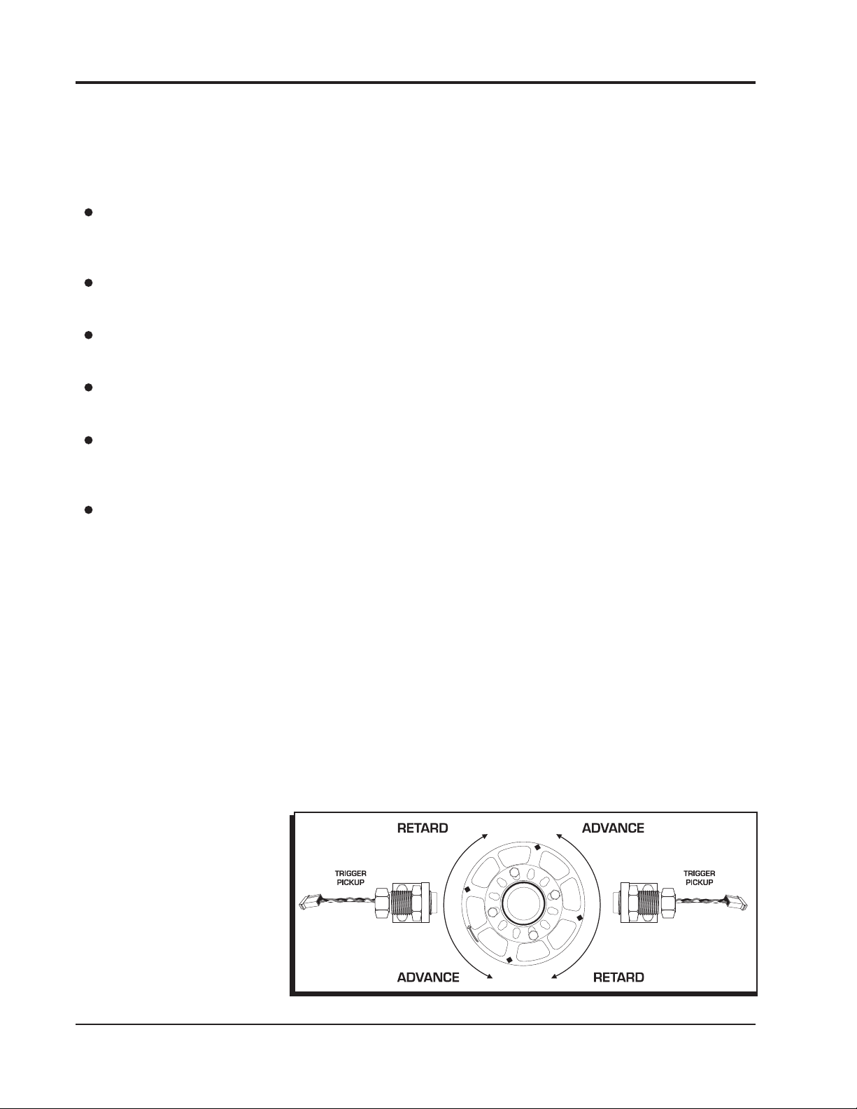
TIMING THE IGNITION SYSTEM
The timing can be adjusted by sliding the pickup holder assembly up or down in the bracket slot. To
retard the timing, move the pickup holder assembly in the direction that the crank trigger wheel rotates.
To advance the timing, move the pickup holder assembly in the opposite direction of the trigger wheel
rotation (Figure 2). Check the
air-gap whenever the timing is
changed.
Note: Do not attempt to adjust
the timing while the engine is
running.
Figure 2 Adjusting the Timing.
M S D • W W W . M S D P ER F O R M A N C E . C O M • ( 9 1 5) 8 5 7 - 5 2 0 0 • F A X ( 91 5 ) 8 57 - 3 3 4 4
Page 3
INSTALLATION INSTRUCTIONS
3
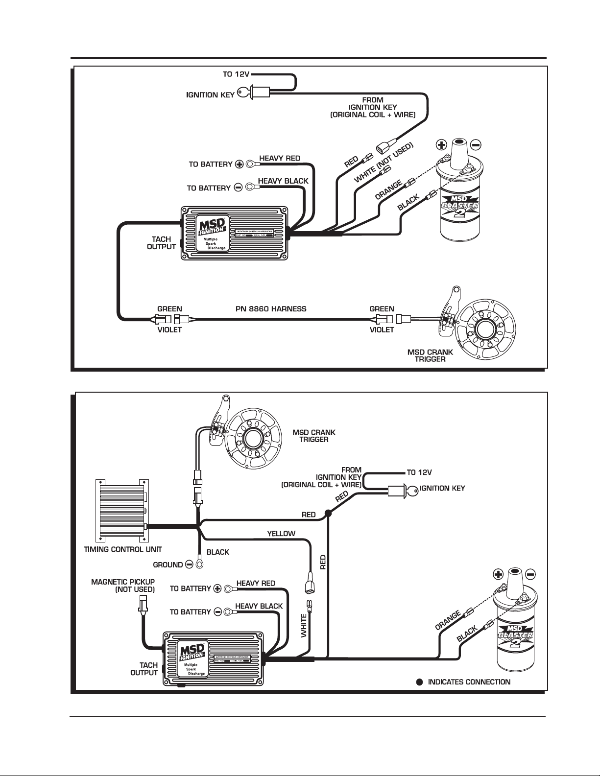
Figure 3 Wiring to an MSD 6AL Ignition Control.
Figure 4 Wiring to an MSD 6AL Ignition and Timing Control.
M S D • W W W . M S D P ER F O R M A N C E . C O M • ( 9 1 5) 8 5 7 - 5 2 0 0 • F A X ( 91 5 ) 8 57 - 3 3 4 4
Page 4

4
INSTALLATION INSTRUCTIONS
Figure 5 Wiring to an MSD Digital-6 Plus or Digital-7 Plus Ignition Control.
Figure 6 Wiring to an MSD 7AL-2 Ignition Control.
M S D • W W W . M S D P ER F O R M A N C E . C O M • ( 9 1 5) 8 5 7 - 5 2 0 0 • F A X ( 91 5 ) 8 57 - 3 3 4 4
Page 5

INSTALLATION INSTRUCTIONS
5
Figure 7 Wiring to an MSD 7AL-2 Ignition and Timing Control.
Figure 8 Wiring to an MSD Programmable Digital-7 Series Ignition Control.
M S D • W W W . M S D P ER F O R M A N C E . C O M • ( 9 1 5) 8 5 7 - 5 2 0 0 • F A X ( 91 5 ) 8 57 - 3 3 4 4
Page 6

6
INSTALLATION INSTRUCTIONS
Figure 9 Wiring to an MSD 8 Ignition Control.
Figure 10 Wiring to an MSD 10 PLUS Ignition.
M S D • W W W . M S D P ER F O R M A N C E . C O M • ( 9 1 5) 8 5 7 - 5 2 0 0 • F A X ( 91 5 ) 8 57 - 3 3 4 4
Page 7

INSTALLATION INSTRUCTIONS
7
Figure 11 Wiring to an MSD Pro Mag 12.
M S D • W W W . M S D P ER F O R M A N C E . C O M • ( 9 1 5) 8 5 7 - 5 2 0 0 • F A X ( 91 5 ) 8 57 - 3 3 4 4
Page 8

TECH NOTES
_________________________________________________________________________________________________________________________
_________________________________________________________________________________________________________________________
_________________________________________________________________________________________________________________________
_________________________________________________________________________________________________________________________
_________________________________________________________________________________________________________________________
_________________________________________________________________________________________________________________________
_________________________________________________________________________________________________________________________
_________________________________________________________________________________________________________________________
_________________________________________________________________________________________________________________________
_________________________________________________________________________________________________________________________
_________________________________________________________________________________________________________________________
_________________________________________________________________________________________________________________________
_________________________________________________________________________________________________________________________
_________________________________________________________________________________________________________________________
_________________________________________________________________________________________________________________________
_________________________________________________________________________________________________________________________
_________________________________________________________________________________________________________________________
_________________________________________________________________________________________________________________________
Service
In case of malfunction, this MSD component will be repaired free of charge according to the terms of the warranty.
When returning MSD components for warranty service, Proof of Purchase must be supplied for verification. After
the warranty period has expired, repair service is based on a minimum and maximum fee.
All returns must have a Return Material Authorization (RMA) number issued to them before
being returned. To obtain an RMA number please contact MSD Customer Service at 1 (888) MSD-7859 or visit
our website at www.msdperformance.com/rma to automatically obtain a number and shipping information.
When returning the unit for repair, leave all wires at the length in which you have them installed. Be sure to include
a detailed account of any problems experienced, and what components and accessories are installed on the vehicle.
The repaired unit will be returned as soon as possible using Ground shipping methods (ground shipping is covered
by warranty). For more information, call MSD at (915) 855-7123. MSD technicians are available from 7:00 a.m. to
5:00 p.m. Monday - Friday (mountain time).
Limited Warranty
M
SD warrants this product to be free from defects in material and workmanship under its intended normal use*,
when properly installed and purchased from an authorized MSD dealer, for a period of one year from the date of
the original purchase. This warranty is void for any products purchased through auction websites. If found to be
defective as mentioned above, it will be repaired or replaced at the option of MSD. Any item that is covered under
this warranty will be returned free of charge using Ground shipping methods.
This shall constitute the sole remedy of the purchaser and the sole liability of MSD. To the extent permitted by
law, the foregoing is exclusive and in lieu of all other warranties or representation whether expressed or implied,
including any implied warranty of merchantability or fitness. In no event shall MSD or its suppliers be liable for special
or consequential damages.
*Intended normal use means that this item is being used as was originally intended and for the original application
as sold by MSD. Any modifications to this item or if it is used on an application other than what MSD markets the
product, the warranty will be void. It is the sole responsibility of the customer to determine that this item will work for
the application they are intending. MSD will accept no liability for custom applications.
M S D • W W W . M S D P ER F O R M A N C E . C O M • ( 9 1 5) 8 5 7 - 5 2 0 0 • F A X ( 91 5 ) 8 57 - 3 3 4 4
© 2012 Autotr onic Co ntrol s Corporation
FRM28731 Revised 12/11 Printed in U.S.A.
 Loading...