

Page 1
MSD Dual Hall HVC Pro-Billet Distributor
Chevrolet - PN 83921, Ford 351W – PN 83922
SB Chrysler - PN 83923, Toyota - PN 83924,
Chevrolet R07 - PN 83925, Dodge - PN 83926
Parts Included:
1 - Distributor
1 - Wire Retainer
1 - Coil Wire Retainer
2 - Retainer Screws
1 - Gasket (Chevy Only)
2 - O-Rings (Chevy Only)
1 - O-Ring (Ford/Chrysler/Toyota Only)
Parts Required:
Distributor Gear
Harness Assembly, PN 8857
HVC Distributor Reluctor Removal
Tool, PN 83492
Note: The HVC Pro-Billet Distributor is NOT supplied with a gear. See page 2 for gears.
IMPORTANT
The MSD HVC Pro-Billet Distributors are the most advanced racing
distributors available. Take the time to read these instructions thoroughly
before installing the distributor. There are a variety of adjustments that
can be made to improve the performance of your engine and should be
understood prior to running the engine.
Use of a distributor spin machine (or equivalent), is recommended to
take full advantage of the HVC's adjustable features. With a degree
wheel and pointer, you will be able to easily and accurately set the
timing of the secondary pickup.
WIRING
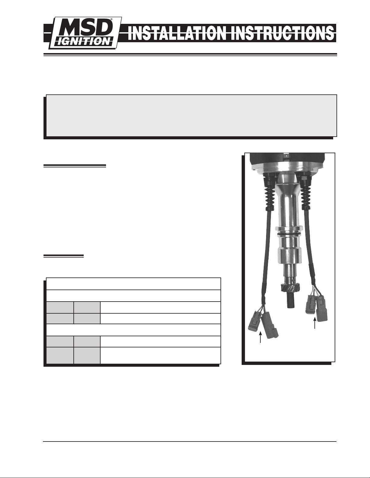
These Distributors have four 2-wire Deutsch connectors that connect
to the ignition control.
2-PIN CONNECTORS
MALE CONNECTOR
BLACK Pin 1 Connect to a common ground.
RED Pin 2 12-volt input. Connect to switched 12 volts.
FEMALE CONNECTOR
BROWN Pin 1 Shielded Ground. Connect to Ground.
WHITE Pin 2 Trigger Wire. Connect to the points input
(White) wire of the MSD Ignition Control.
PICKUP ALIGNMENT AND ADJUSTMENTS
PRIMARY
NON-ADJUSTABLE
PICKUP
Figure 1 Separate Pickup Connectors.
SECONDARY
ADJUSTABLE
PICKUP
The HVC Pro-Billet Distributor features a primary and secondary pickup.
These are stacked together with the primary positioned on the bottom. The primary is fixed while the
secondary pickup is adjustable +/- 8°. The pickups are aligned at the factory at 0° advance/retard. The
position of the secondary pickup will need to be set to your specifications.
When installing the distributor there is an alignment indicator (Figure 3). By aligning the reluctor paddle with
the indicator, the timing will be within approximately +/- 3° of the desired amount. To adjust the secondary
pickup, loosen the two allen head screws on the top pickup. Next, turn the eccentric using an 11/32" wrench
to move the pickup (Figure 3). Secure the screws when the desired timing is reached.
M S D I G N I T I O N • w ww . ms di g ni ti o n. co m • ( 91 5) 8 57 -5 20 0 • F AX ( 91 5) 85 7- 3 34 4
Page 2

2 INSTALLATION INSTRUCTIONS
RED
INDICATES CONNECTION
RED
TO
IGNITION
SWITCH
12VOLTS
AUTOMATIC COIL
SELECTOR
PN 8210
SPDT SWITCH
PN 8807
PRIMARY
GROUND
BROWN
TO TACH*
BROWN
TO TACH*
COIL
GROUND
ORANGE (+)
BLACK (-)
ORANGE (+)
BLACK (-)
HEAVY RED
TO BATTERY (+)
TO GROUND (-)
HEAVY BLACK
WHITE
TO REV CONTROL PN 8738
HEAVY RED
TO BATTERY (+)
TO GROUND (-)
HEAVY BLACK
WHITE
TO REV CONTROL PN 8738
COIL
BLACK
BLACK
* TO SWITCH TACH SIGNALS, MSD OFFERS A TACH SPLITTER, PN 8911.
SECONDARY
MAG PICKUP
(NOT USED)
MAG PICKUP
(NOT USED)
WHITE
BROWN
BROWN
RED
RED
WHITE
TO GROUND
PN 8857 HARNESS KIT
HVC PRO-BILLET
DISTRIBUTOR
Figure 2 Wiring a Complete Redundant System.
SERVICE
ADJUSTING
ECCENTRIC
MSD designed the HVC Pro-Billet Distributor to be completely
serviceable. Replacement parts are listed below.
SERVICE PARTS:
4 - Pin Deutsch Connector - PN 8181
Rotor - PN 8484
Extension Harness (set) - PN 8857
Reluctor Installation/Removal Tool - PN 83492
Finished Reluctor - PN 8349
Unfinished Reluctor - PN 83491
Pickup Assemblies
CW - Lower Chevrolet - PN 87571
CW - Upper Chevrolet - PN 87573
CCW - Lower Ford/Mopar/Toyota - PN 87572
CCW - Upper Ford/Mopar/Toyota - PN 87574
An unfinished reluctor, PN 83491 is available. This reluctor does not have
the individual cylinder paddles machined. Individual cylinder timing values
can be determined on the dyno using our electronic controls. These values
can then be machined into the reluctor.
SERVICE PROCEDURE
LOWER HOUSING
To replace the distributor bearings and seals, the lower housing must be disassembled. Both disassembly
and re-assembly require the lower housing to be heated for proper clearance. Review the following procedure
before starting the service. Figures 5 and 6 show exploded views of the five distributors available.
M S D I G N I T I O N • w ww . ms di g ni ti o n. co m • ( 91 5) 8 57 -5 20 0 • F AX ( 91 5) 85 7- 3 34 4
Bronze Gears
Chevrolet
Standard - PN 8471
+0.006" - PN 8472
+0.009" - PN 84722
+0.012" - PN 84723
+0.015" - PN 84724
Ford Windsor
Standard - PN 8585
Chrysler
Standard - PN 8525
+0.006" - PN 8526
Toyota
N/A: Contact TRD for
information
Figure 3 Adjusting the Secondary Pickup.
Figure 4 Unfinished
Reluctor, PN 83491.
SECONDARY
PICKUP
ALIGNMENT
INDICATOR
Page 3

HOUSING
MSD 20793
CHEVY
PN 83921
SHAFT
ASY 27223
BEARING
HDW 20788
SEAL
HDW 10080
BUSHING
HDW 10081
SLIP
COLLAR
ASSEMBLY
(PN 8539)
SEAL
HDW 11143
HOUSING
MSD 20885
FORD
PN 83922
BEARING
HDW 20788
SHAFT
ASY 27224
SPACER
MSD 21553
BEARING
HDW 11142
SEAL
HDW 10080
HOUSING
MSD 21262
CHRYSLER
PN 83923
BEARING
HDW 20788
SHAFT
ASY 27225
SPACER
MSD 21717
SHIM
MSD 11082
BEARING
HDW 13913
HOUSING
MSD 27433
SEAL
HDW 11143
TOYOTA
PN 83924
BEARING
HDW 20788
SHAFT
ASY 27226
SPACER
MSD 27646
BEARING
HDW 11142
8-32 X 1.25 SHCS
SCW 15508
#8 WASHER
WAS 21181
PICKUP UPPER
SEE SERVICE
PARTS PAGE 2.
PICKUP LOWER
SEE SERVICE
PARTS PAGE 2.
#10 WASHER
WAS 21186
HOUSING
MSD 27231
ARP-STUD
SCW 27285
STRAIN RELIEF
HDW 21491
10-32 x .625 SHCS
SCW 11067
NUT-ECCENTRIC
MSD 27230
SCREW - PLASTITE
SCW 20311
COIL WIRE
RETAINER
MSD 25843
SEE SERVICE PARTS PAGE 2.
PN 8408 CAP AND
RETAINER KIT
SCREW
10-32 X 1.50 PAN-PHIL
SCW 20168
BOLT-DOWN
MSD 23940
WASHER
WAS 23066
10-32 X .625 SHCS
SCW 11067
CAP-A-DAPT
MSD 22256
HOLD-DOWN
MSD 22582
ROTOR
PN 8484
1/4 - 28 NUT
NUT 27286
RELUCTOR
MSD 27229
SEE SERVICE PARTS PAGE 2.
PN 8408 CAP AND
RETAINER KIT
HOUSING
MSD 20793
CHEVY
PN 83921
SHAFT
ASY 27223
BEARING
HDW 20788
SEAL
HDW 10080
BUSHING
HDW 10081
SLIP
COLLAR
ASSEMBLY
(PN 8539)
SEAL
HDW 11143
HOUSING
MSD 20885
FORD
PN 83922
BEARING
HDW 20788
SHAFT
ASY 27224
SPACER
MSD 21553
BEARING
HDW 11142
SEAL
HDW 10080
HOUSING
MSD 21262
CHRYSLER
PN 83923
BEARING
HDW 20788
SHAFT
ASY 27225
SPACER
MSD 21717
SHIM
MSD 11082
BEARING
HDW 13913
HOUSING
MSD 27443
SEAL
HDW 11143
TOYOTA
PN 83924
CHEVROLET R07
PN 83925
DODGE
PN 83926
BEARING
HDW 20788
SHAFT
ASY 27226
SPACER
MSD 27646
BEARING
HDW 11142
HOUSING
MSD 28865
SEAL
HDW 10080
BEARING
HDW 20788
SHAFT
ASY 27226
SPACER
MSD 27646
BEARING
HDW 13913
SEAL
HDW 10080
HOUSING
MSD 28156
BEARING
HDW 20788
SHAFT
ASY 28155
BUSHING
HDW 10081
INSTALLATION INSTRUCTIONS 3
1. Remove dist rib utor
cap.
2. Remove the reluctor. Use
the installation/removal
tool PN 83492 to prevent
the shaft from turning
(Figure 7). Remove
the reluctor attaching
bolt using a 5/16", 12pt
deepwell socket.
3. Remove the two bolts
that retain the pickups.
4. Remove the four bolts
retaining the upper
housing and take it off.
5. Remove the distributor
gear and any spacers if
so equipped.
6. The upper bearing is
an interference fit and
needs to be heated to
be removed. Place the
lower housing and shaft
assembly in an oven at
300°F for approximately
30 minu tes. When
heated, the shaft and
bearing assembly
should slide out of the aluminum housing. A slight tap on the shaft may be necessary.
7. If distributor is equipped with a lower bearing remove it while the housing is hot. If equipped with a lower
bushing, it can be replaced if necessary.
Figure 5 Upper Housing Exploded Views.
8. Remove and replace the two seals in the housing. The new seals install with their flat sides facing each
other. Lubricate the seals with grease (Figure 8).
9. Place the lower housing in an oven at 250° for approximately 30 minutes.
M S D I G N I T I O N • w ww . ms di g ni ti o n. co m • ( 91 5) 8 57 -5 20 0 • F AX ( 91 5) 85 7- 3 34 4
Figure 6 Lower Housing Exploded Views.
Page 4

10. While the lower housing
is heating, install the
new bearing on the
shaft (Figure 9).
11. I n s t a l l t h e sha f t
3/4"
WRENCH
5/16"
SOCKET
FLAT SIDES OF
SEALS MUST
FACE EACH
OTHER.
ass embl y int o the
lower housing. It is
fully seated when the
bea ring pr otru des
approximately 0.005”
– 0.010” out of the
TOOL
PN 83492
Figure 7 Removing the Reluctor.
housing (Figure 10). If the clearance is more, the
housing may have cooled too much before the bearing was fully
Figure 8 Installing New Seals.
installed.
12. Install the gear.
a. Chevrolet – Check clearance between gear and housing. It should be
greater than 0.015”. If under 0.015” the bearing may not be seated
correctly (Figure 11).
b. Ford – Install gear spacer. Press on gear leaving 0.005” clearance
between it and the spacer.
c. Mopar R5 – Install gear spacer and shim. Check clearance between
gear and spacer. It should be between 0.005”-0.010”. If under 0.005”
the bearing may not be seated correctly.
Figure 9 Installing the New
Bearing.
d. Toyota – Install gear spacer with roll pin. Press on gear until it stops against the spacer.
13. Assemble the upper housing.
14. Install Pickup screws.
15. Install reluctor using special tool PN 83492. Apply moly lube to the nut and torque to 10 lb-ft. (Figure 7).
16. Adjust pickup phasing and tighten the pickup bolts.
BEARING SHOULD
PROTRUDE BY
0.005"-0.010"
GREATER THAN
0.015"
Figure 10 Checking Bearing to Housing Clearance.
Figure 11 Checking Gear to Housing Clearance.
Service
In case of malfunction, this MSD component will be repaired free of charge according to the terms of the warranty.
When returning MSD components for warranty service, Proof of Purchase must be supplied for verification. After
the warranty period has expired, repair service is based on a minimum and maximum fee.
All returns must have a Return Material Authorization (RMA) number issued to them before
being returned. To obtain an RMA number please contact MSD Customer Service at 1 (888) MSD-7859 or
visit our website at www.msdignition.com/rma to automatically obtain a number and shipping information.
When returning the unit for repair, leave all wires at the length in which you have them installed. Be sure to include
a detailed account of any problems experienced, and what components and accessories are installed on the vehicle.
The repaired unit will be returned as soon as possible using Ground shipping methods (ground shipping is covered
by warranty). For more information, call MSD Ignition at (915) 855-7123. MSD technicians are available from 7:00
a.m. to 6:00 p.m. Monday - Friday (mountain time).
M S D I G N I T I O N • w ww . ms di g ni ti o n. co m • ( 91 5) 8 57 -5 20 0 • F AX ( 91 5) 85 7- 3 34 4
© 2007 Autotronic Con trols Corpo ration
FRM28906 Revised 08/07 Printed in U.S.A.
 Loading...