

Page 1
MSD Pro-Billet Ready-to-Run
Chrysler V8 Distributor
PN 8388; 318, 340, 360, PN 8386; 383, 400
PN 8387; 426, 440
ONLINE PRODUCT REGISTRATION: Register your MSD product online and you’ll be entered
in our monthly 8.5mm Super Conductor Spark Plug Wire give-away! Registering your product
will help if there is ever a warranty issue with your product and helps the MSD R&D team create
new products that you ask for! Go to www.msdperformance.com/registration.
Important: Read these instructions before attempting the installation.
Parts Included:
1 - Pro-Billet Distributor
1 - Rotor, PN 8467
1 - Distributor Cap
1 - Advance Kit
1 - O-ring Seal
Note: The PN 8386 and PN 8387 distributors feature HEI style plug wire terminals. You may need to
change the terminals and boots of your wires. MSD offers a kit, PN 8848, that comes with nine
HEI style boots and terminals.
TIMING FUNCTIONS
Before continuing with the installation, here are a few definitions you should be aware of:
Initial Timing: This is the base timing (also referred to as idle timing) of the engine before the
centrifugal advance begins.
1 - Gray Tach Jumper
1 - Parts Bag
Replacement Cap
Distributor PN 8386, PN 8387 - PN 8431
Distributor PN 8388 - PN 8437 or PN 8433
:
Centrifugal Advance: The centrifugal (or mechanical) advance mechanism is made up of weights,
springs, advance cams, and an advance stop bushing. The amount and rate of advance that your
distributor is capable of is determined by the centrifugal timing. If you ever wish to lock out the
centrifugal advance, refer to the centrifugal advance section.
Total Timing: This is the total of the initial timing pl u s the centri f u g a l advance added tog e t h e r.
Example: 10° Initial + 25° centrifugal = 35° Total Timing (When checking Total timing, disconnect
anc cap the vacuum canister and plug the vacuum line).
Vacuum Advance: The vacuum advance will advance the timing up to 10° during partial throttle driving (with
15 lbs. of vacuum). The vacuum line should be routed to a ported vacuum outlet above the throttle plates.
RPM LIMIT AND TACHOMETER INFORMATION
Tach Signal: The Ready-to-Run Distributor features a Gray Tach Output wire which provides a clean signal
for most tachometers and even some aftermarket fuel injection systems. The signal output
is a 12 volt square wave, 20° duty cycle. This wire is also responsible for programming the
built-in rev limiter.
Rev Limiter: The Ready-to-Run Distributor has a built-in rev limit that can easily be adjusted from 2,000
rpm to over 10,000 rpm. The default is 10,000 rpm. To set the rev limiter, run the engine to half
the desired rpm then ground the Gray tach wire (a jumper is supplied) for approximately one
second. Every time the key is turned to the On position, the tach will display the programmed
rpm limit. See page 8 for the programming procedure.
M S D • W W W . M S D P E R F O R M A N C E . C O M • ( 9 1 5 ) 8 5 7 - 5 2 0 0 • F A X ( 9 1 5 ) 8 5 7 - 3 3 4 4
Page 2

2 INSTALLATION INSTRUCTIONS
CHOOSING AN ADVANCE CURVE
The function of the advance curve is to match the ignition timing to the burning rate of the fuel and
speed (rpm) of the engine. Any factor that changes the burning rate of the fuel or the engine speed
can cause a need for an ignition timing change. Figure 1 shows some of the factors that will affect
engine timing.
FACTOR Advance Timing Retard Timing
For For
Cylinder Pressure Low High
Vacuum High Low
Energy of Ignition Low High
Fuel Octane High Low
Mixture (Air/Fuel) Rich Lean
Temperature Cool Hot
Combustion Chamber Shape Open Compact
Spark Plug Location Offset Center
Combustion Turbulence Low High
Load Light Heavy
Figure 1 Ignition Timing Factors.
As you can see from the chart, most factors will change throughout the range of the engine operation.
The timing mechanism of the distributor must make timing changes based on these factors.
Example: An engine has 11:1 compression, a high energy ignition and turns 5,500 rpm. With the
specifications given, you will have to retard the timing for the high compression, low rpm and high
energy ignition. By comparing the engine’s specifications against the chart, a usable timing guideline
can be found. Engines with a combination of items from both columns will require a timing that is
set in the mid range.
Obviously a full technical explanation of correct ignition timing would be very complicated. The best
way to arrive at a suitable ignition curve for your engine is to use the Ignition Timing Factors Chart
as a guide and compare it to the Advance Graphs in Figure 4 until a suitable curve is found. When
selecting your advance curve, use detonation (engine ping) as an indicator of too much advance,
and a decrease in power as an indicator of too little advance.
TIPS ON SELECTING AN ADVANCE CURVE
• Use as much initial advance as possible without encountering excessive starter load.
• Start the centrifugal advance just above the idle rpm.
• The starting point o f the centrifugal advance c urve is controlled by the installed length and
tension of the spring.
• How quickly the centrifugal advance (slope) comes in is controlled by the spring stiffness. The
stiffer the spring, the slower the advance curve.
• The amount of advance is controlled by the advance bushing. The bigger the bushing, the
smaller the amount of advance.
M S D • W W W . M S D P E R F O R M A N C E . C O M • ( 9 1 5 ) 8 5 7 - 5 2 0 0 • F A X ( 9 1 5 ) 8 5 7 - 3 3 4 4
Page 3
INSTALLATION INSTRUCTIONS 3
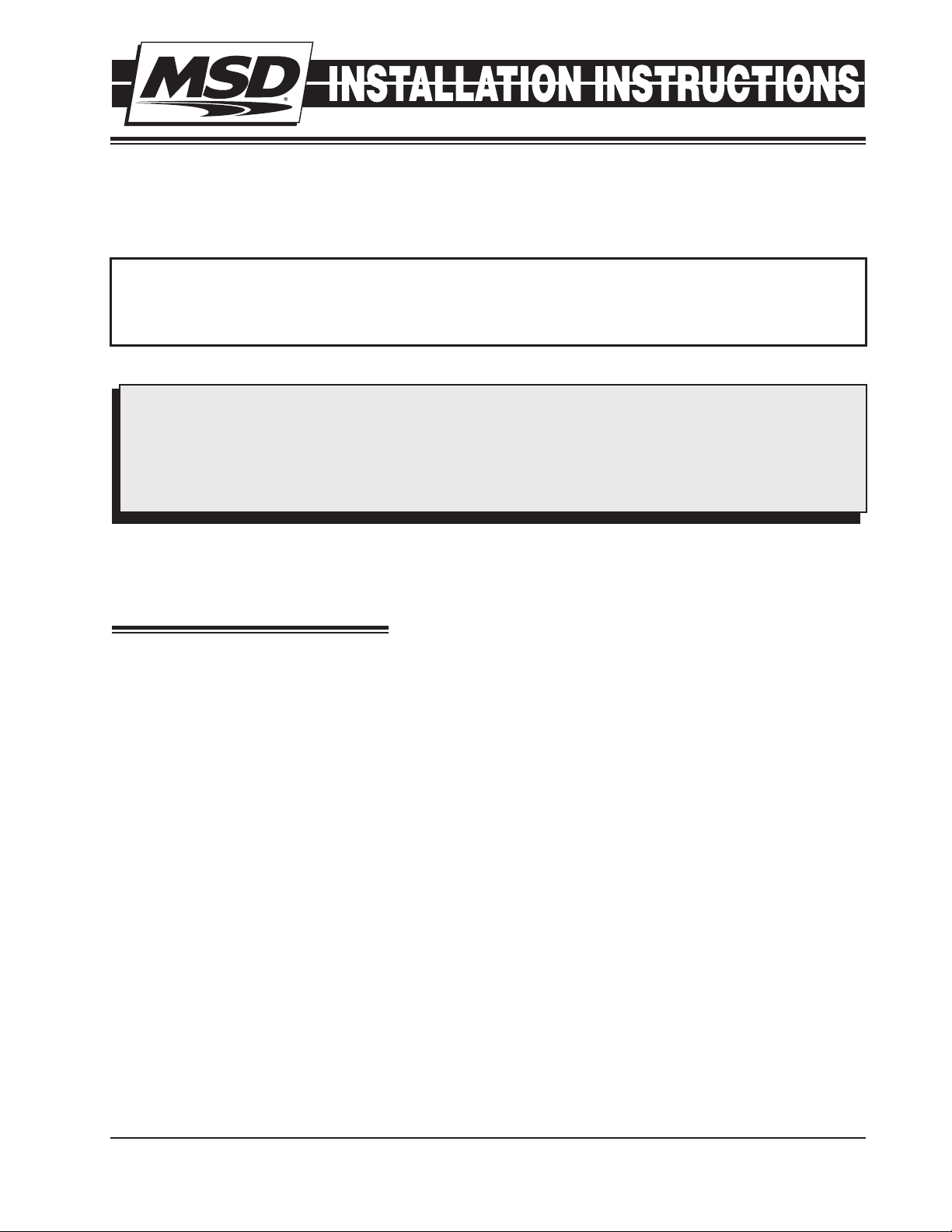
CENTRIFUGAL ADVANCE CURVE
SELECTING THE ADVANCE SPRINGS
The rate, or how quick the advance comes in
is determined by the type of springs which are
installed on the distributor. The MSD distributors
are equip ped with two Heavy Silver springs
install ed. These will give you the slowest
advance curve possible. The parts kit contains
two additional sets of springs which can be used
to match the advance curve to your particular
application. Refer to the Spring Combination
Chart (Figure 3) for combinations tha t can be
achieved.
To change the springs, remove the cap and rotor
and use needlenose pliers to remove the springs.
Be sure the new springs seat in the groove on
the pin.
Timing Curve From Factory
Figure 2 The Factory Equipped Curve.
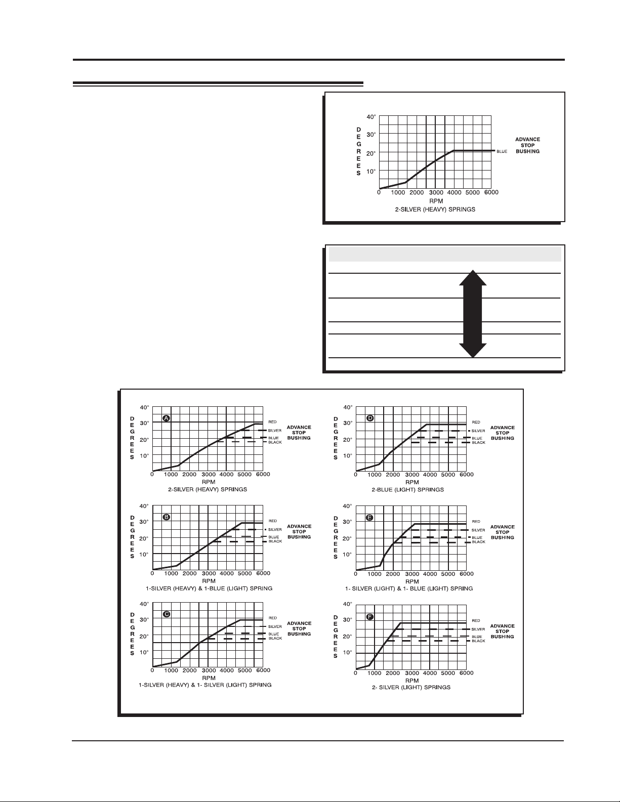
SPRING COMBINATION RATE OF ADVANCE FIGURE 4
2- Heavy Silver SLOWEST A
1- Heavy Silver B
1- Light Blue
1-Heavy Silver C
1-Light Silver
2- Light Blue D
1- Light Silver E
1- Light Blue
2- Light Silver FASTEST F
Figure 3 Spring Combination Chart.
Figure 4 Advance Curves.
M S D • W W W . M S D P E R F O R M A N C E . C O M • ( 9 1 5 ) 8 5 7 - 5 2 0 0 • F A X ( 9 1 5 ) 8 5 7 - 3 3 4 4
Page 4

4 INSTALLATION INSTRUCTIONS
SELECTING THE ADVANCE STOP
BUSHING
Three different advance stop bushings are supplied
in the distributor kit. The distributor comes with a
Blue (21°) bushing already installed. If a different
amount of centrifugal advance is desired, follow the
next procedure to change the bushings. The chart
in Figure 5 gives the size and approximate degrees
for the corresponding bushings.
CHANGING THE ADVANCE STOP
BUSHINGS
1. Remove the distributor cap and rotor.
2. Remove the locknut and washer on the bottom
of the advance assembly (Figure 6).
3. Remove the bushing and install the new one.
Install the washer and locknut.
BUSHING SIZE APPROXIMATE
CRANKSHAFT
DEGREES
Red-Smallest - 0.283" 28
Silver - 0.313" 25
Blue - 0.343" 21
Black-Largest - 0.375" 18
Figure 5 Advance Stop Bushing Chart.
Figure 6 Changing the Advance Stop Bushing.
LOCKING OUT THE CENTRIFUGAL
ADVANCE
1. Remove the cap and rotor.
2. R e move th e a dvan c e s p ring s , w e ight s
and the advance stop bushing from the
advance assembly.
3. Remove the roll-pin from the shaft and slide the
retaining sleeve down (Figure 7).
4. Slide the shaft two inches out of the housing.
5. R ot at e t h e s ha ft 18 0 ° a n d i ns er t t h e
advance stop bushing pin into the small
hole on the advance plate (Figure 8).
6. I n st a ll the loc k nu t an d wash e r to th e
advance stop bushing pin.
7. Install the retaining sleeve and roll-pin.
Figure 7 Removing the Retaining Sleeve.
Figure 8 Locking Out the Centrifugal Advance.
M S D • W W W . M S D P E R F O R M A N C E . C O M • ( 9 1 5 ) 8 5 7 - 5 2 0 0 • F A X ( 9 1 5 ) 8 5 7 - 3 3 4 4
Page 5

INSTALLATION INSTRUCTIONS 5
OPTIONAL VACUUM ADVANCE LOCKOUT
If you do not want to use the vacuum advance canister
of the MSD Distributor, MSD has supplied the distributor
with a lockout mechanism. The Lockout bolts in the
position of the vacuum canister and will hold the pickup
assembly firmly in place. The installation is easiest with
the distributor out of the engine.
1. Remove the two Allen head screws that hold the
advance canister (Figure 9).
2. Remove the snap ring that holds the magnetic
pickup assembly in place. This is easy to do with
a set of snap ring pliers by straddling one of the
reluctor paddles.
3. Gently lift up on the mag pickup plate and slide the
vacuum canister out.
4. Install the Lockout Plate in place of the canister.
Install the two retaining screws.
5. Install the supplied screw and washer through the
Lockout and tighten. It is important to make sure
the pickup plate is parallel with the housing of the
distributor (Figure 10). If it is cocke d or slanted,
the paddles of the reluctor may contact the pickup.
Check the clearance by rotating the distributor shaft.
If necessary, use the supplied shims under the
Lockout hold-down to correctly position the pickup
plate.
RELUCTOR
PADDLES
CANISTER
SCREWS
Figure 9 Removing the Vacuum Canister.
MAG PICK-UP
PLATE
SNAP
RING
Note: If no shims were r equired, use one beneath
the washer of the Lock-Out Hold Down Screw.
6. Aft er checking the reluctor to pickup clearance,
tighten the Lockout retaining screws and install the
snap ring.
7. Install the distributor, rotor and cap. Check the
timing when complete.
Note: Do not forget to plug the original va cuum
advance hose.
Figure 10 Checking Installation of the Lockout Plate.
M S D • W W W . M S D P E R F O R M A N C E . C O M • ( 9 1 5 ) 8 5 7 - 5 2 0 0 • F A X ( 9 1 5 ) 8 5 7 - 3 3 4 4
Page 6

6 INSTALLATION INSTRUCTIONS
INSTALLING THE DISTRIBUTOR
1. Remove the existing distributor cap without
disconnecting any of the spark plug wires.
2. With the cap off, crank the engine until the
rotor is aimed at a fixed point on the engine.
Note this position by making a mark (Figure
11).
3. Place the distributor cap b ack on and
note which plug wire the rotor is pointing
to. MARK THE SPARK PLUG WIRES and
remove the distributor cap.
4. Disconnect the wiring from the distributor.
5. Loosen the distributor hold-down clamp,
slide the clamp out of the way and lift the
distributor out of the engine.
6. Install the supplied O-ring seal in the groove
on the distributor land. Apply a thin layer
of oil to the housing O-ring.
7. Install the distributor making sure that the
rotor comes to rest pointing at the fixed
mark. If the distributor will not fully seat with
the rotor pointing to the marked position,
you may need to rotate the oil pump shaft
until the rotor lines up and the distributor
fully seats.
8. Position and tighten the hold-down clamp onto the distributor.
9. Install the rotor and distributor cap. It is recommended to use a drop of Blue Loctite on the distributor
cap hold down bolts.
10. Install the spark plug wires from the old cap one at a time to ensure correct location.
11. Connect the supplied wiring harness to the distributor. Route the wires to their connections as
shown in Figure 12.
12. Page 8 shows how to set the rev limiter and connect the tachometer.
Figure 11 Marking the Rotor Location.
Figure 11 Connecting an MSD Ignition Control.
M S D • W W W . M S D P E R F O R M A N C E . C O M • ( 9 1 5 ) 8 5 7 - 5 2 0 0 • F A X ( 9 1 5 ) 8 5 7 - 3 3 4 4
Page 7

INSTALLATION INSTRUCTIONS 7
GRAY TO
TACH INPUT
Figure 12 Wiring the Ready-to-Run Chrysler Distributor.
GRAY TO
TACH INPUT
Figure 13 Connecting an MSD Ignition Control.
M S D • W W W . M S D P E R F O R M A N C E . C O M • ( 9 1 5 ) 8 5 7 - 5 2 0 0 • F A X ( 9 1 5 ) 8 5 7 - 3 3 4 4
Page 8

TACHOMETER INFORMATION
The MSD Ready-to-Run has a Gray wire that provides a 12 volt square wave, 20° duty cycle tachometer
signal that will trigger most tachometers. It is recommended to connect this lead to your tach’s trigger
input wire and check its operation. Note that the rpm limiter is extremely accurate and due to the variety
of tachometers available, there may be differences in the displayed rpm.
PROGRAMMING THE REV LIMIT
A tachometer is required to set the rev limit. The limit is programmed by
running the engine at half the desired rpm, then momentarily grounding
the Gray tach output wire from the MSD. A Gray jumper wire is supplied
to connect to the tach with another tee-splice coming off to use for
programming. A switch may also be installed to ease adjustments of
the limiter (Figure 14). The default rpm limit is 10,000 rpm and the limit
is adjustable from 2,000 - over 10,000 rpm..
1. Start the engine and bring the rpm to half the desired rev limit (for a
6,000 rpm limit, raise and hold the rpm to 3,000).
2. While holding the rpm steady, short the Gray tach wire to ground
for approximately one second. Note that the tach will go to zero
while grounded.
3. The tach will now display the programmed rev limit amount for two
seconds. If this value does not register on the tach, repeat the procedure and try a different ground
source.
4. To confirm the rev limit value, turn the ignition key to the On position (without cranking the engine). The
rev limit value will be displayed for two seconds on the tachometer.
OPTIONAL
PROGRAMMING
SWITCH
TO
TACH
Figure 14 Setting the Rev Limiter.
JUMPER GRAY
Note: This rpm confirmation only displays when the Gray wire is being used to trigger the tachometer.
Service
In case of malfunction, this MSD component will be repaired free of charge according to the terms of the warranty.
When returning MSD components for warranty service, Proof of Purchase must be supplied for verification. After
the warranty period has expired, repair service is based on a minimum and maximum fee.
All returns must have a Return Material Authorization (RMA) number issued to them before
being returned. To obtain an RMA number please contact MSD Customer Service at 1 (888) MSD-7859 or visit
our website at www.msdperformance.com/rma to automatically obtain a number and shipping information.
When returning the unit for repair, leave all wires at the length in which you have them installed. Be sure to include
a detailed account of any problems experienced, and what components and accessories are installed on the vehicle.
The repaired unit will be returned as soon as possible using Ground shipping methods (ground shipping is covered
by warranty). For more information, call MSD at (915) 855-7123. MSD technicians are available from 7:00 a.m. to
5:00 p.m. Monday - Friday (mountain time).
Limited Warranty
M
SD warrants this product to be free from defects in material and workmanship under its intended normal use*,
when properly installed and purchased from an authorized MSD dealer, for a period of one year from the date of
the original purchase. This warranty is void for any products purchased through auction websites. If found to be
defective as mentioned above, it will be repaired or replaced at the option of MSD. Any item that is covered under
this warranty will be returned free of charge using Ground shipping methods.
This shall constitute the sole remedy of the purchaser and the sole liability of MSD. To the extent permitted by
law, the foregoing is exclusive and in lieu of all other warranties or representation whether expressed or implied,
including any implied warranty of merchantability or fitness. In no event shall MSD or its suppliers be liable for special
or consequential damages.
*Intended normal use means that this item is being used as was originally intended and for the original application
as sold by MSD. Any modifications to this item or if it is used on an application other than what MSD markets the
product, the warranty will be void. It is the sole responsibility of the customer to determine that this item will work for
the application they are intending. MSD will accept no liability for custom applications.
M S D • W W W . M S D P E R F O R M A N C E . C O M • ( 9 1 5 ) 8 5 7 - 5 2 0 0 • F A X ( 9 1 5 ) 8 5 7 - 3 3 4 4
© 2012 Autotr onic Con trols Corporation
FRM30249 Revised 01/12 Printed in U.S.A.
 Loading...