

Page 1
MSD Pro-Billet Dual Pickup Ford Distributor
PN 8380; 351C-460, PN 8384; 351W
PN 8382; 289/302
Important: Read these Instructions before attempting the installation.
Parts Included:
1 - Pro-Billet Distributor 1 - O-ring Seal
1 - Rotor, PN 8423 1 - Tube of Gear Lubricant
1 - Distributor Cap, PN 8408 2 - 1.5" Self Tapping Screws
1 - Advance Kit 1 - Wire Retainer
Note: The Dual Pickup Distributors must be used with an MSD Ignition Control(s).
TIMING FUNCTIONS
Before continuing with the installation, here are a few definitions you should be aware of:
Initial Timing: This is the base timing (also referred to as idle timing) of the engine before the
centrifugal advance begins.
Centrifugal Advance: The centrifugal (or mechanical) advance mechanism is made up of weights,
springs, advance cams, and an advance stop bushing. The amount and rate of advance that
your distributor is capable of is determined by the centrifugal timing. If you ever wish to lock out
the centrifugal advance, refer to the centrifugal advance section.
Total Timing: This is the total of the initial timing plus the centrifugal advance added together.
Example: 10° Initial + 25° centrifugal = 35° Total Timing.
Note: MSD Distributors are supplied with the heavy (slow) advance springs installed. This is to
prevent detonation in certain applications. Review the information on pages 2-3 to
determine the best advance curve for your application.
AUTOTRONIC CONTROLS CORPORATION • 1490 HENRY BRENNAN DR., EL PASO, TEXAS 79936 • (915) 857-5200 • FAX (915) 857-3344
Page 2

2 INSTALLATION INSTRUCTIONS
CHOOSING AN ADVANCE CURVE
The function of the advance curve is to match the ignition timing to the burning rate of the fuel
and speed (rpm) of the engine. Any factor that changes the burning rate of the fuel or the
engine speed can cause a need for an ignition timing change. Figure 1 shows some of the
factors that will affect engine timing.
FACTOR Advance Timing Retard Timing
For For
Cylinder Pressure Low High
Vacuum High Low
Energy of Ignition Low High
Fuel Octane High Low
Mixture (Air/Fuel) Rich Lean
Temperature Cool Hot
Combustion Chamber Shape Open Compact
Spark Plug Location Offset Center
Combustion Turbulence Low High
Load Light Heavy
Figure 1 Ignition Timing Factors.
As you can see from the chart, most factors will change throughout the range of the engine
operation. The timing mechanism of the distributor must make timing changes based on these
factors.
By comparing the engine’s specifications against the chart, a usable timing guideline can be
found. Engines with a combination of items from both columns will require a timing that is set in
the mid range.
Obviously a full technical explanation of correct ignition timing would be very complicated. The
best way to arrive at a suitable ignition curve for your engine is to use the Ignition Timing Factors
Chart as a guide and compare it to the Advance Graphs in Figure 4 until a suitable curve is found.
When selecting your advance curve, use detonation (engine ping) as an indicator of too much
advance, and a decrease in power as an indicator of too little advance.
TIPS ON SELECTING AN ADVANCE CURVE
• Use as much initial advance as possible without encountering excessive starter load.
• Start the centrifugal advance just above the idle rpm.
• The starting point of the centrifugal advance curve is controlled by the installed length and
tension of the spring.
• How quickly the centrifugal advance (slope) comes in is controlled by the spring stiffness. The
stiffer the spring, the slower the advance curve.
• The amount of advance is controlled by the advance bushing. The bigger the bushing, the
smaller the amount of advance.
AUTOTRONIC CONTROLS CORPORATION • 1490 HENRY BRENNAN DR., EL PASO, TEXAS 79936 • (915) 857-5200 • FAX (915) 857-3344
Page 3
INSTALLATION INSTRUCTIONS 3
CENTRIFUGAL ADVANCE CURVE
SELECTING THE ADVANCE
SPRINGS
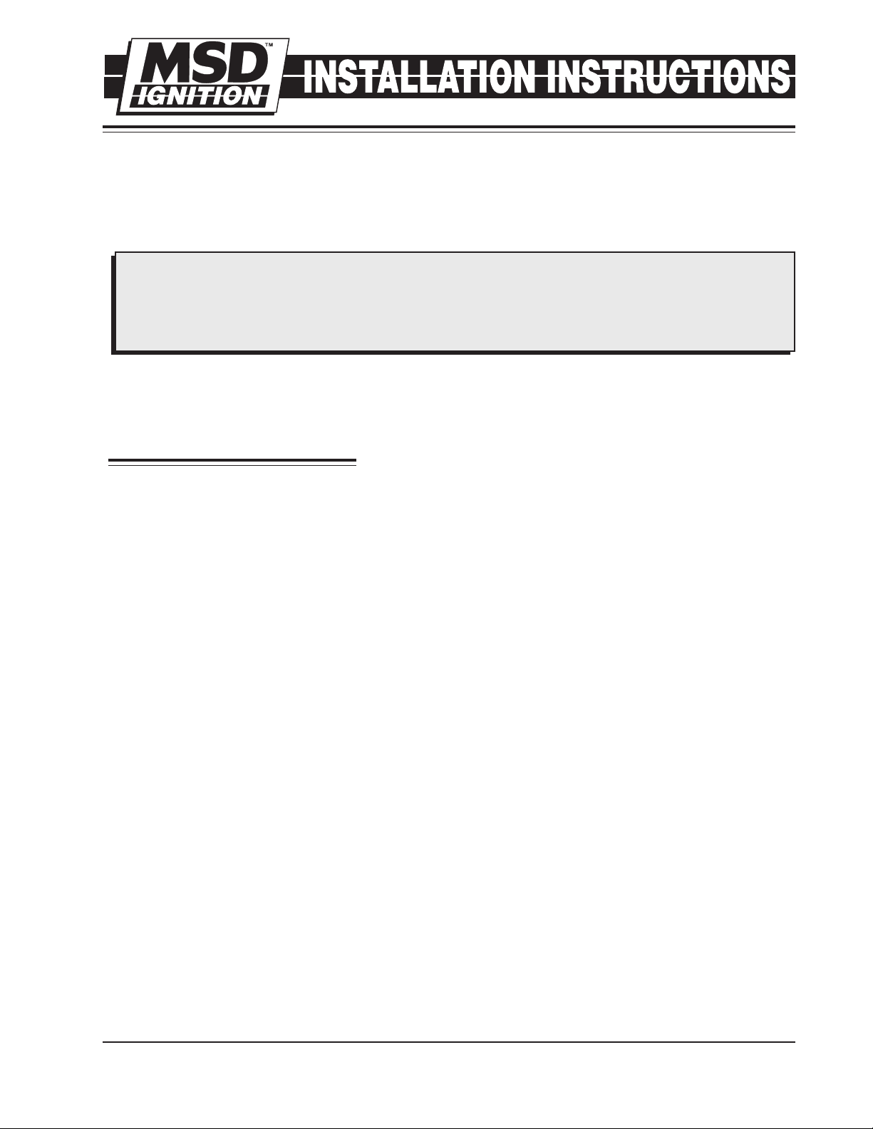
The rate, or how quick the advance comes
in is determined by the type of springs
which are installed on the distributor. The
MSD distributors are equipped with two
Heavy Silver springs installed. These will
give you the slowest advance curve
possible (Figure 2). The parts kit contains
two additional sets of springs which can be
used to match the advance curve to your
particular application. Refer to the Spring
Combination Chart (Figure 3) for
combinations that can be achieved.
To change the springs, remove the cap and
rotor and use needlenose pliers to remove
the springs. Be sure the new springs seat in
the groove on the pin.
Timing Curve From Factory
Figure 2 The Factory Equipped Curve.
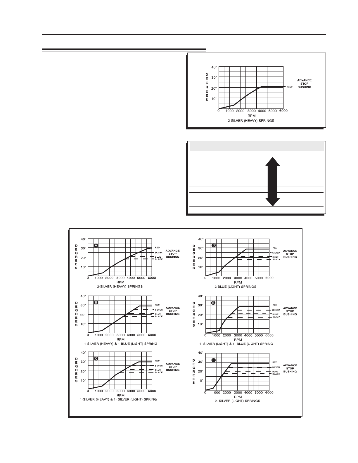
SPRING COMBINATION RATE OF ADVANCE FIGURE 4
2- Heavy Silver SLOWEST A
1- Heavy Silver B
1- Light Blue
1-Heavy Silver C
1-Light Silver
2- Light Blue D
1- Light Silver E
1- Light Blue
2- Light Silver FASTEST F
Figure 3 Spring Combination Chart.
Figure 4 Advance Curves.
AUTOTRONIC CONTROLS CORPORATION • 1490 HENRY BRENNAN DR., EL PASO, TEXAS 79936 • (915) 857-5200 • FAX (915) 857-3344
Page 4

4 INSTALLATION INSTRUCTIONS
SELECTING THE ADVANCE STOP
BUSHING
Three different advance stop bushings are
supplied in the distributor kit. The distributor
comes with a Blue (21°) bushing already installed.
If a different amount of centrifugal advance is
desired, follow the next procedure to change the
bushings. The chart in Figure 5 gives the size
and approximate degrees for the corresponding
bushings.
CHANGING THE ADVANCE STOP
BUSHINGS
1. Remove the distributor cap and rotor.
2. Remove the locknut and washer on the bottom
of the advance assembly (Figure 6).
3. Remove the bushing and install the new one.
Install the washer and locknut.
BUSHING SIZE APPROXIMATE
CRANKSHAFT
DEGREES
Red-Smallest 28
Silver 25
Blue 21
Black-Largest 18
Figure 5 Advance Stop Bushing Chart.
Figure 6 Changing the Advance Stop Bushing.
LOCKING OUT THE CENTRIFUGAL
ADVANCE
1. Remove the cap and rotor.
2. Remove the advance springs, weights and the
advance stop bushing from the advance
assembly.
3. Remove the roll-pin from the shaft and slide
the retaining sleeve down. It should not be
necessary to remove the gear (Figure 7).
4. Slide the shaft two inches out of the housing.
5. Rotate the shaft 180° and insert the advance
stop bushing pin into the small hole on the
advance plate (Figure 8).
6. Install the locknut and washer to the advance
stop bushing pin.
7. Install the retaining sleeve and roll-pin.
Figure 7 Removing the Retaining Sleeve.
Figure 8 Locking Out the Centrifugal Advance.
AUTOTRONIC CONTROLS CORPORATION • 1490 HENRY BRENNAN DR., EL PASO, TEXAS 79936 • (915) 857-5200 • FAX (915) 857-3344
Page 5

INSTALLATION INSTRUCTIONS 5
INSTALLING THE DISTRIBUTOR
1. Remove the existing distributor cap
without disconnecting any of the
spark plug wires.
2. With the cap off, crank the engine
until the rotor is aimed at a fixed point
on the engine. Note this position by
making a mark (Figure 9).
3. Place the distributor cap back on and
note which plug wire the rotor is
pointing to. MARK THE SPARK PLUG
WIRES and remove the distributor
cap.
4. Disconnect the wiring from the
distributor.
5. Loosen the distributor hold-down
clamp,slide the clamp out of the way
and lift the distributor out of the
engine.
6. Install the supplied O-ring seal in the
groove on the distributor land. Apply a thin layer of oil to the housing O-ring.
7. Apply a liberal amount of the supplied break-in lubricant to the gear.
8. Install the distributor making sure that the rotor comes to rest pointing at the fixed mark. If
the distributor will not fully seat with the rotor pointing to the marked position, you may
need to rotate the oil pump shaft until the rotor lines up and the distributor fully seats.
9. Position and tighten the hold-down clamp onto the distributor.
10. Install the rotor and distributor cap. Install the spark plug wires from the old cap one at a
time to ensure correct location.
11. An optional wire retainer is supplied to secure the wires in place. Align the mounting bosses
and use the two self-tapping screws to hold the retainer in place.
Figure 9 Marking the Rotor Location.
AUTOTRONIC CONTROLS CORPORATION • 1490 HENRY BRENNAN DR., EL PASO, TEXAS 79936 • (915) 857-5200 • FAX (915) 857-3344
Page 6

6 INSTALLATION INSTRUCTIONS
Figure 11 Wiring with MSD 6TN, 6ALN, or 6-HVC Ignition Controls.
TECH NOTES
________________________________________________________________________________________________________________________
________________________________________________________________________________________________________________________
________________________________________________________________________________________________________________________
________________________________________________________________________________________________________________________
________________________________________________________________________________________________________________________
________________________________________________________________________________________________________________________
________________________________________________________________________________________________________________________
________________________________________________________________________________________________________________________
________________________________________________________________________________________________________________________
________________________________________________________________________________________________________________________
________________________________________________________________________________________________________________________
________________________________________________________________________________________________________________________
________________________________________________________________________________________________________________________
________________________________________________________________________________________________________________________
________________________________________________________________________________________________________________________
________________________________________________________________________________________________________________________
AUTOTRONIC CONTROLS CORPORATION • 1490 HENRY BRENNAN DR., EL PASO, TEXAS 79936 • (915) 857-5200 • FAX (915) 857-3344
Page 7

INSTALLATION INSTRUCTIONS 7
Figure 12 Wiring with MSD 6A Series Ignition Controls.
TECH NOTES
________________________________________________________________________________________________________________________
________________________________________________________________________________________________________________________
________________________________________________________________________________________________________________________
________________________________________________________________________________________________________________________
________________________________________________________________________________________________________________________
________________________________________________________________________________________________________________________
________________________________________________________________________________________________________________________
________________________________________________________________________________________________________________________
________________________________________________________________________________________________________________________
________________________________________________________________________________________________________________________
________________________________________________________________________________________________________________________
________________________________________________________________________________________________________________________
________________________________________________________________________________________________________________________
________________________________________________________________________________________________________________________
________________________________________________________________________________________________________________________
________________________________________________________________________________________________________________________
AUTOTRONIC CONTROLS CORPORATION • 1490 HENRY BRENNAN DR., EL PASO, TEXAS 79936 • (915) 857-5200 • FAX (915) 857-3344
Page 8

TECH NOTES
________________________________________________________________________________________________________________________
________________________________________________________________________________________________________________________
________________________________________________________________________________________________________________________
________________________________________________________________________________________________________________________
________________________________________________________________________________________________________________________
________________________________________________________________________________________________________________________
________________________________________________________________________________________________________________________
________________________________________________________________________________________________________________________
________________________________________________________________________________________________________________________
________________________________________________________________________________________________________________________
________________________________________________________________________________________________________________________
________________________________________________________________________________________________________________________
________________________________________________________________________________________________________________________
________________________________________________________________________________________________________________________
________________________________________________________________________________________________________________________
________________________________________________________________________________________________________________________
Service
In case of malfunction, this MSD component will be repaired free of charge according to the terms
of the warranty. When returning MSD components for service, Proof of Purchase must be supplied for
warranty verification. After the warranty period has expired, repair service is charged based on a minimum
and maximum charge.
Send the unit prepaid with proof of purchase to the attention of: Customer Service Department,
Autotronic Controls Corporation, 12120 Esther Lama, Suite 114, El Paso, Texas 79936.
When returning the unit for repair, leave all wires at the length in which you have them installed.
Cutting wires close to the unit will void your warranty. Be sure to include a detailed account of any
problems experienced, and what components and accessories are installed on the vehicle.
The repaired unit will be returned as soon as possible after receipt, COD for any charges. For more
information, call the MSD Customer Service Line (915) 855-7123. MSD technicians are available from
8:00 a.m. to 5:00 p.m. Monday - Friday (mountain time).
Limited Warranty
A
utotronic Controls Corporation warrants MSD Ignition products to be free from defects in material
and workmanship under normal use and if properly installed for a period of one year from date of
purchase. If found to be defective as mentioned above, it will be replaced or repaired if returned prepaid
along with proof of date of purchase. This shall constitute the sole remedy of the purchaser and the sole
liability of Autotronic Controls Corporation. To the extent permitted by law, the foregoing is exclusive
and in lieu of all other warranties or representations whether expressed or implied, including any implied
warranty of merchantability or fitness. In no event shall Autotronic Controls Corporation be liable for
special or consequential damages.
AUTOTRONIC CONTROLS CORPORATION • 1490 HENRY BRENNAN DR., EL PASO, TEXAS 79936 • (915) 857-5200 • FAX (915) 857-3344
FRM23365 Revised 12/02 Printed In U.S.A.
 Loading...