

Page 1
MSD HEAT Digital HEI Module
PN 83647
ONLINE PRODUCT REGISTRATION: Register your MSD product online and you’ll be entered in our
monthly 8.5mm Super Conductor Spark Plug Wire give-away! Registering your product will help if there
is ever a warranty issue with your product and helps the MSD R&D team create new products that you
ask for! Go to www.msdperformance.com/registration.
This Module is a performance replacement for GM’s 4-Pin HEI Module. It features a programmable
rev limiter for overrev protection. The Module will mount in a stock HEI housing (by removing the
original condenser assembly) or in MSD’s Pro-Billet HEI Distributor, PN 8365. A GM Coil can be used
or for maximum performance, use MSD’s HEI Coil, PN 8225.
Parts Included:
1 - HEI Module, PN 83647
1 - Tube of Heat Sink Compound
Note: A tachometer is required to program the rev limit.
INSTALLATION
1. Mark the location of the spark plug wires on the cap prior to removal.
2. Remove the cap, rotor, module and condenser (if equipped) from the original distributor.
3. Apply a liberal coat of the Heat Sink Compound to the aluminum base of the Module.
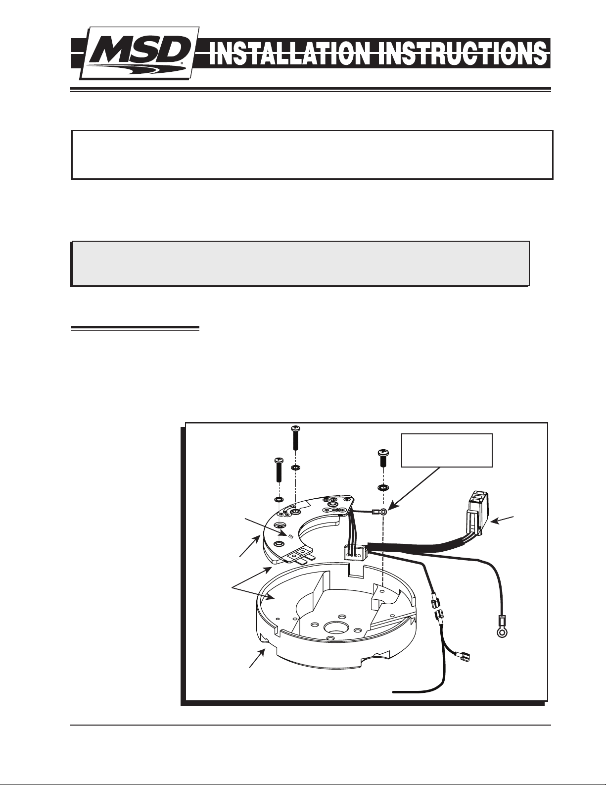
4. Route the wiring harness out of the housing and position the short Black wire to ground with one
of the mounting screws (Figure 1).
5. Position the module in the distributor then locate the two screws and star washers to secure the
module (Figure 1).
6. Reinstall the rotor
and cap.
REV LIMIT
BYPASS
JUMPER
1 - Gray Tach Wire
2 - Mounting Screws and Star Washers
1 - Low Resistance Rotor Bushing, PN 8412
SCREWS AND
STAR WASHERS
CONNECT SHORT
BLACK WIRE
TO GROUND
CONNECTOR
CAP
DIGITAL
HEI MODULE
APPLY
HEAT SINK
COMPOUND
DISTRIBUTOR
HOUSING
TO TACH
GRAY
TACH
OUTPUT
USE TO
PROGRAM TACH
Figure 1 Installing the Module.
M S D • W W W . M S D P E R F O R M A N C E . C O M • ( 9 1 5 ) 8 5 7 - 5 2 0 0 • F A X ( 9 1 5 ) 8 5 7 - 3 3 4 4
Page 2
2 INSTALLATION INSTRUCTIONS
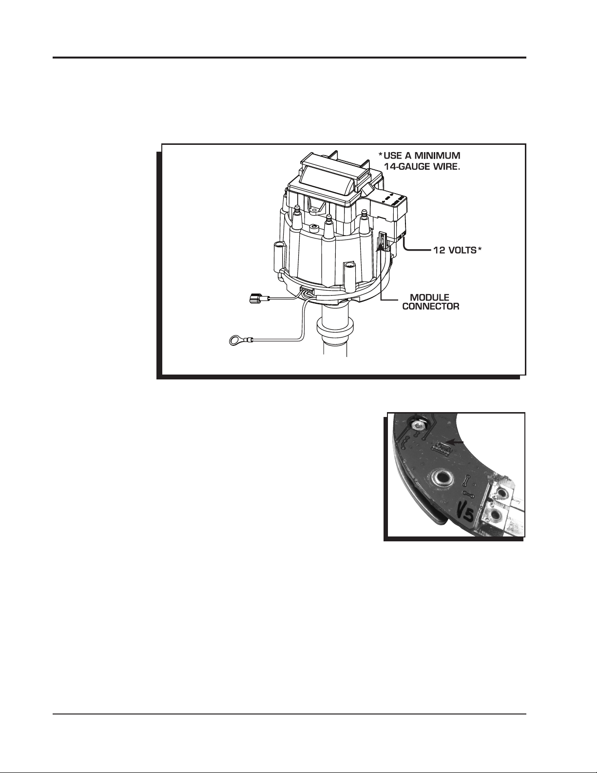
7. Connect the HEI Module harness to the Distributor Cap followed by the 12 volt (BAT) wire. This
wire should be at least 14-gauge (Figure 2).
8. Connect the long black wire to the engine block for a solid ground.
9. See the next page for tachometer and rev limit programming.
10. It is recommended to install the supplied low resistance rotor bushing. This improves the spark
transfer from the coil to the rotor tip. Remove the coil cover and coil. Replace the rotor bushing.
GRAY
TO TACH
OUTPUT
LONG BLACK
TO ENGINE
GROUND
Figure 2 Connecting the Module and Tach Lead.
TACHOMETER INFORMATION
The HEAT Digital HEI Module has a Gray wire that provides a 12 volt
square wave, 20° tachometer signal that will trigger most tachometers.
It is recommended to connect this lead to your tach’s trigger input
wire and check its operation. If the tach requires a higher voltage
signal, connect its input wire to the Tach terminal on the HEI Cap
(Coil-/Tach). Note that the rpm limiter is extremely accurate and due
to the variety of tachometers available, there may be differences in
the displayed rpm.
No Rev Limit: To disable the rev limit function, cut and remove the
jumper shown in Figure 3.
JUMPER
Figure 3 Disable the Rev Limit.
M S D • W W W . M S D P E R F O R M A N C E . C O M • ( 9 1 5 ) 8 5 7 - 5 2 0 0 • F A X ( 9 1 5 ) 8 5 7 - 3 3 4 4
Page 3

INSTALLATION INSTRUCTIONS 3
PROGRAMMING THE REV LIMIT
A tachometer is required to set the rev limit. The limit is
programmed by running the engine at half the desired
rpm, then momentarily grounding the Gray tach output
wire from the MSD. A Gray jumper wire is supplied to
connect to the tach with another tee-splice coming off to
use for programming. A switch may also be installed to
ease adjustments of the limiter (Figure 4). The default rpm
limit is 10,000 rpm.
OPTIONAL
PROGRAMMING
SWITCH
1. Start the engine and bring the rpm to half the desired
rev limit (for a 6,000 rpm limit, raise the rpm to 3,000).
2. While holding the rpm steady, short the Gray tach wire
TO
TACH
GRAY
to ground for approximately one second. Note that the
tach will go to zero while grounded.
3. The tach will now display the programmed rev limit
amount for two seconds. If this value does not register
Figure 4
on the tach, repeat the procedure and try a different
ground source.
Note: This rpm confirmation only displays when the HEI Gray wire is being used to trigger the
tachometer.
REV LIMITER VERIFICATION
The MSD HEAT HEI Module has an optional built-in Rev Limiter Verification feature. When the key
is in the On position (not cranking or running), an rpm signal is sent to the tachometer to verify the
unit's rev limit setting. With this function users can be sure of their rev limit settings before each drive
To enable this feature, follow the procedure below.
Note: It is important to note that this feature should not be used with EFI systems. When activated,
an rpm signal is sent to the tachometer. With an aftermarket EFI system, this could activate the
injectors causing a flooding situation.
ENABLE REV LIMIT VERIFICATION
1. With the ignition switch in the off position, ground the Gray tach output wire.
2. With the Gray wire connected to ground, turn the ignition on without starting the engine.
3. Hold the Gray tach output wire to ground for seven seconds. (AT LEAST five seconds.)
4. Release the wire from ground before ten seconds have passed.
5. To confirm the process has worked, cycle turn the key On. The tachometer should sweep to the
rpm limit set on the ignition.
To deactivate the verification feature, repeat the process.
Playback Tach: If you use a playback tach, be sure to check the high rpm value prior to turning the
key to the On position. When the key is in the On position, the rev limit will be displayed and may
override the tach memory.
M S D • W W W . M S D P E R F O R M A N C E . C O M • ( 9 1 5 ) 8 5 7 - 5 2 0 0 • F A X ( 9 1 5 ) 8 5 7 - 3 3 4 4
Page 4

TECH NOTES
_________________________________________________________________________________________________________________________
_________________________________________________________________________________________________________________________
_________________________________________________________________________________________________________________________
_________________________________________________________________________________________________________________________
_________________________________________________________________________________________________________________________
_________________________________________________________________________________________________________________________
_________________________________________________________________________________________________________________________
_________________________________________________________________________________________________________________________
_________________________________________________________________________________________________________________________
_________________________________________________________________________________________________________________________
_________________________________________________________________________________________________________________________
_________________________________________________________________________________________________________________________
_________________________________________________________________________________________________________________________
_________________________________________________________________________________________________________________________
_________________________________________________________________________________________________________________________
_________________________________________________________________________________________________________________________
_________________________________________________________________________________________________________________________
_________________________________________________________________________________________________________________________
Service
In case of malfunction, this MSD component will be repaired free of charge according to the terms of the warranty.
When returning MSD components for warranty service, Proof of Purchase must be supplied for verification. After
the warranty period has expired, repair service is based on a minimum and maximum fee.
All returns must have a Return Material Authorization (RMA) number issued to them before
being returned. To obtain an RMA number please contact MSD Customer Service at 1 (888) MSD-7859 or visit
our website at www.msdperformance.com/rma to automatically obtain a number and shipping information.
When returning the unit for repair, leave all wires at the length in which you have them installed. Be sure to include
a detailed account of any problems experienced, and what components and accessories are installed on the vehicle.
The repaired unit will be returned as soon as possible using Ground shipping methods (ground shipping is covered
by warranty). For more information, call MSD at (915) 855-7123. MSD technicians are available from 7:00 a.m. to
5:00 p.m. Monday - Friday (mountain time).
Limited Warranty
M
SD warrants this product to be free from defects in material and workmanship under its intended normal use*,
when properly installed and purchased from an authorized MSD dealer, for a period of one year from the date of
the original purchase. This warranty is void for any products purchased through auction websites. If found to be
defective as mentioned above, it will be repaired or replaced at the option of MSD. Any item that is covered under
this warranty will be returned free of charge using Ground shipping methods.
This shall constitute the sole remedy of the purchaser and the sole liability of MSD. To the extent permitted by
law, the foregoing is exclusive and in lieu of all other warranties or representation whether expressed or implied,
including any implied warranty of merchantability or fitness. In no event shall MSD or its suppliers be liable for special
or consequential damages.
*Intended normal use means that this item is being used as was originally intended and for the original application
as sold by MSD. Any modifications to this item or if it is used on an application other than what MSD markets the
product, the warranty will be void. It is the sole responsibility of the customer to determine that this item will work for
the application they are intending. MSD will accept no liability for custom applications.
M S D • W W W . M S D P E R F O R M A N C E . C O M • ( 9 1 5 ) 8 5 7 - 5 2 0 0 • F A X ( 9 1 5 ) 8 5 7 - 3 3 4 4
© 2012 Autotr onic Co ntrols Corpor ation
FRM30524 Revised 04/12 Printed in U.S.A.
 Loading...