

Page 1
MSD Power Grid System Controller
PN 7730/77303
ONLINE PRODUCT REGISTRATION: Register your MSD product online. Registering your product
will help if there is ever a warranty issue with your product and helps the MSD R&D team create
new products that you ask for! Go to www.msdperformance.com/registration.
Parts Included:
1 - System Controller, PN 7730 / PN 77303
1 - 4Gb SD Card
1 - Micro-USB Cable
1 - MSD View CD-Rom
1 - Fiber Optic Plug
Accessories (Purchased Separately):
Inductive Cam Sync Kit, PN 7555
Hub Connector, PN 7740 / PN 77403
Slew Rate and Time Based Rev Limiter, PN 7761
Boost Retard Module, PN 7762
Manual Launch Controller, PN 7751
WARNING: During installation, disconnect the battery cables. When disconnecting, always remove
the Negative cable first and install it last.
Note: Solid core spark plug wires cannot be used with an MSD Ignition Control.
Note: A crank trigger is recommended to supply the input signal to the Power Grid Ignition System to
ensure the most precise timing and rpm control.
1 - CAN Terminator Cap
1 - Power Cable-Loose
1 - Mag Cable
1 - 2-pin Legacy Cable
1 - Main Cable Loose
1 - Parts Bag
Racepak V-Net Tee
9” - 280-CA-VM-T009
18” - 280-CA-VM-T018
36” - 280-CA-VM-T036
OPERATION
DIGITAL OPERATION
The MSD Power Grid System Controller uses a high speed RISC microcontroller to control the ignition’s
output while constantly analyzing the various inputs such as launch, burnout, and step wires; trigger signals,
rpm, and CAN-Bus data. The high speed controller can make extremely quick updates to the ignition output,
timing, and rpm limits while maintaining +/- 0.1° timing and +/- 1 rpm resolution. The circuits and controller of
this system have been designed for superior protection against Electro Magnetic Interference (EMI).
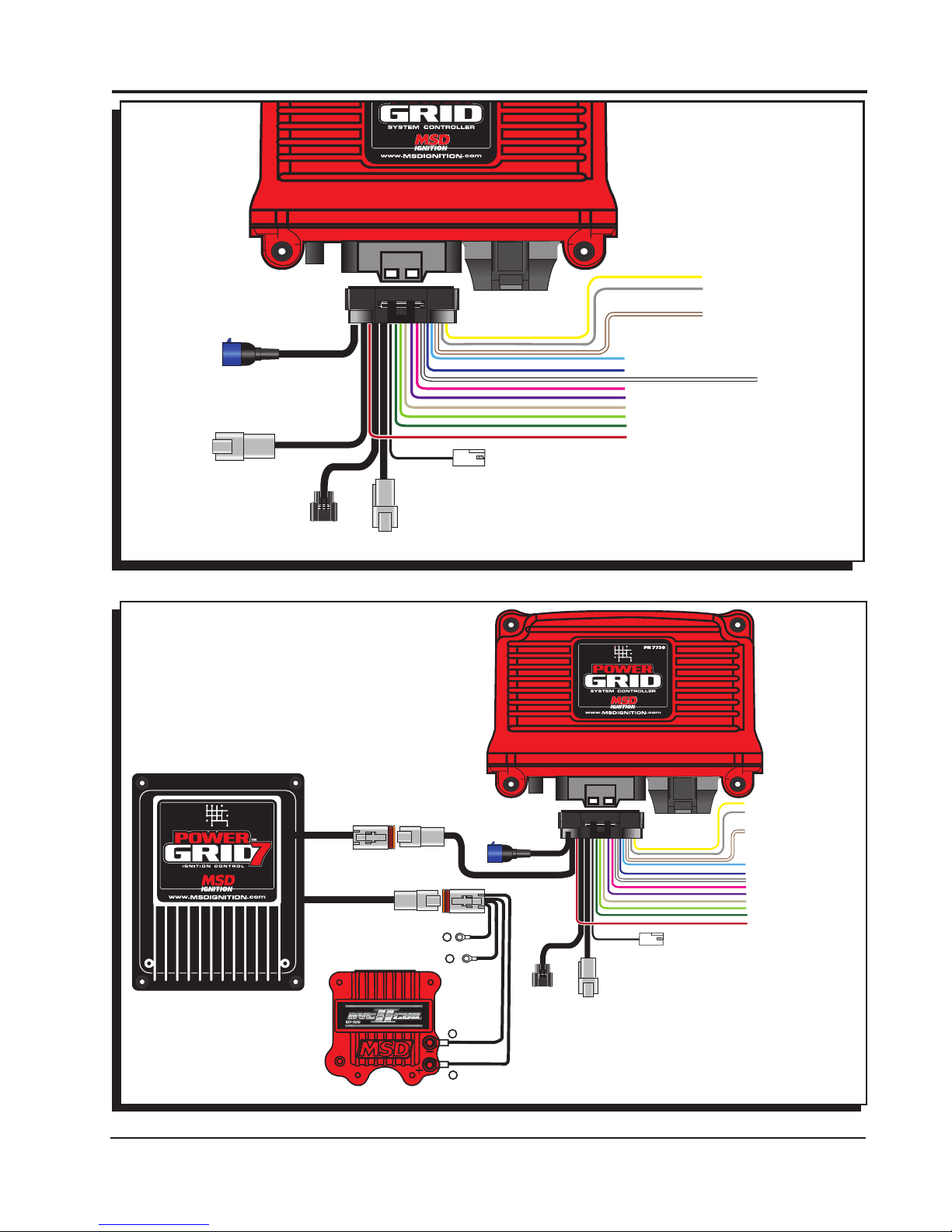
The Power Grid System Controller, PN 7730 / PN 77303, is designed to be used with the Power Grid-7
Ignition Control, PN 7720. This is a high output CD ignition control. The Ignition System allows for the System
Controller to be mounted on top of the Power Grid-7 to save space and provide a neat, compact installation.
The System Controller can also be used with other MSD Ignitions such as the 7AL-2, MSD 8-Plus, and the
Pro-Mag series. In order to use the rev limiting features of the System Controller the paired ignition must
have a built-in Soft Touch Rev Control that uses plug-in RPM modules. Pages 10-12 show wiring diagrams
for a variety of different ignition options.
MSD • WWW.MSDPERFORMANCE.COM • (915) 855-7123 • FAX (915) 857-3344
Page 2

2 INSTALLATION INSTRUCTIONS
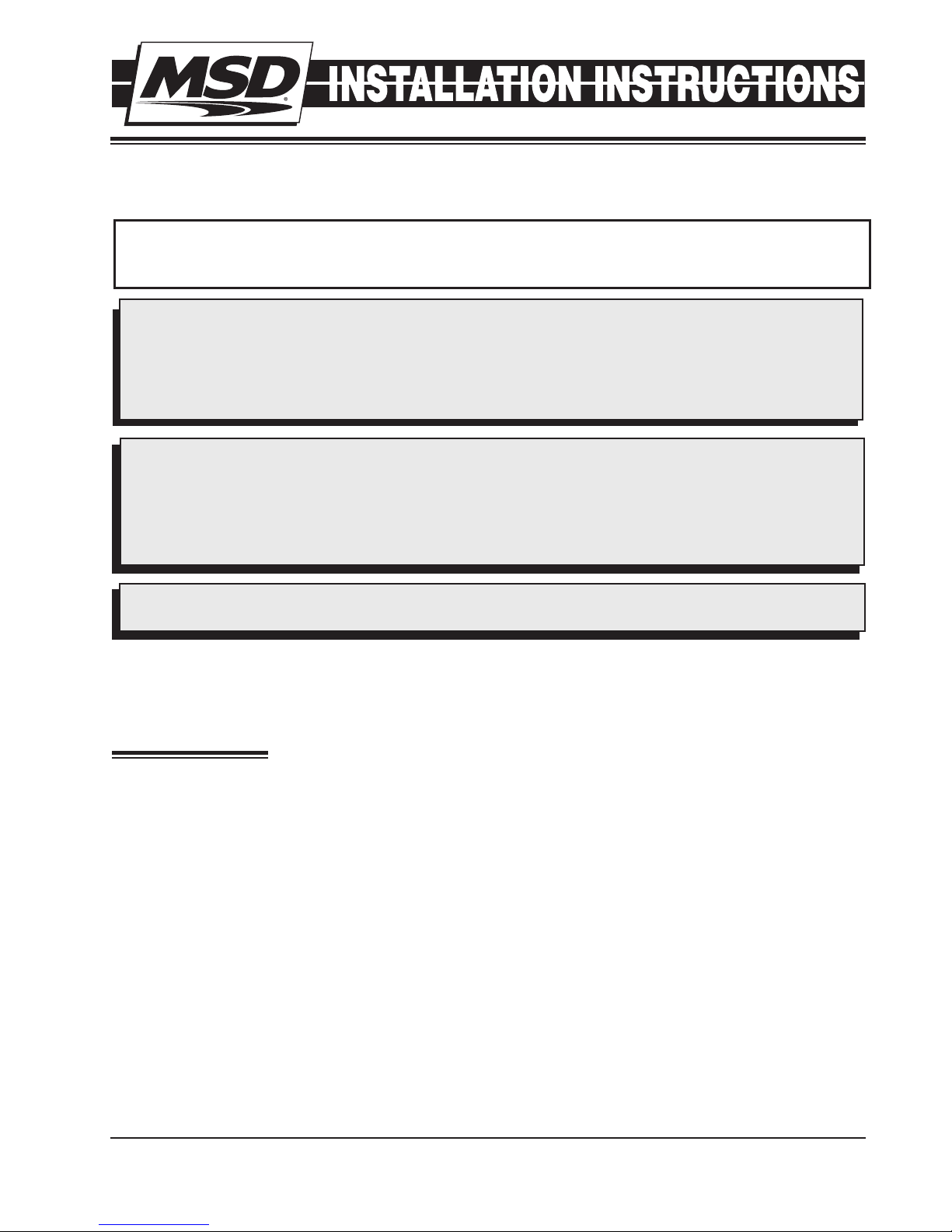
WIRING FEATURES
Leading
Group
4-Pin
Connector
(to PN 7720
or Power
Cable if not
used with
PN 7720)
LOOSE
WIRES
2-Pin
Connector
(Legacy)
3-Pin
Connector
Racepak
Assembly
6-Pin
Connector
(to Hub/
Modules)
Wire
Color PIN Function Description
BLACK 16 GROUND Ignition supply Ground wire. Connect to battery negative (-) terminal
or engine block.
ORANGE 17 BATT POWER Battery supply wire. Connects to battery positive (+) terminal or battery
junction. Note: Do not connect to the alternator.
YEL/WHT 33 TRIGGER OUT Trigger output for electronic ignition amplifiers.
RED 34 POWER OUT On/Off switch wiring. This wire supplies switched 12V power to the
7720.
RED 15 IGN 12V switched (Ignition)
GRAY 18 TACH Tach output. This wire will provide a 12 volt square wave tach signal.
WHITE 32 POINTS IN Trigger input from electronic ignition amplifiers, an ECU’s trigger or
points.
YELLOW 1 SHIFT LIGHT Shift Light output wire. It can handle up to 3 amps continuous to ground
when enabled.
LT BLUE 4 BURN OUT Burnout Rev Limit. When 12 volts are applied the Burnout Rev Limit is
active. This disables the Slew Rate rev limits and overrides other rev limits.
It is recommended to have this wire switched from an outside source, such
as the crew chief before the burnout and while staging the car.
DK BLUE 21 LAUNCH This wire activates the Launch Rev Limit and is the main reset wire for
several features of the Ignition. When 12 volts are applied to this wire it
will activate the Launch Rev Limit. It also resets the shift light, the gear
indicator to first gear, the Launch Retard curve and select Gear 1 curve.
When 12 volts is removed, the Launch Time begins as does the Gear 1
curve. When 12 volts are applied the Slew Rate Rev limit will be disabled
as well as the Time-Based Rev Limit curve.
PINK 22 STEP 1 Step 1 retard enabled with +12 volt input AND above Step 1 Rpm value
OR Gear 2 Select.
VIOLET 5 STEP 2 Step 2 retard enabled with +12 volt input AND above Step 2 Rpm value
OR Gear 3 Select.
TAN 23 STEP3 Step 3 retard enabled with +12 volt input AND above Step 3 Rpm value
OR Gear 4 Select.
LT GREEN 6 STEP4 Step 4 retard enabled with +12 volt input AND above Step 4 Rpm value
OR Gear 5 Select.
GREEN 10 STEP5 Step 5 retard enabled with +12 volt input AND above Step 5 Rpm value
OR spool rev limiter.
BRN/WHT 19 RPM SW RPM/Time switch output wire. It can switch up to 3 amps continuous
to ground when enabled.
YELLOW 7 RELAY LO Network Ignition Mode: Cam sync output to Racepak systems for
individual cylinder timing.
YELLOW 24 RELAY HI Legacy Ignition Mode: Rev limiter output to legacy ignition..
GREEN 8 MAG- This is a magnetic pickup, 2-pin connector. Plugs into an MSD
VIOLET 9 MAG+ Distributor or Crank Trigger pickup. Violet is positive, Green is negative.
BROWN 25 SHIELD Note: When this connector is used, the white POINTS IN wire is not
connected. Brown connects to ground.
WHITE 11 VNET HI Communicates data acquisition information with RacePak system.
BLACK VNET LO Only used to plug into VNet.
RED 13 MSD CAN HI Supplies 12V switched power to add on module units. Also communicates
BROWN 27 SHIELD
RED 29 POWER OUT
BLACK 30 MSD CAN LO
BLACK 31 MSD CAN GND
between modules and Power Grid System Controller. This connector
is only used with modules added onto the system. This is for the MSD
CAN-Bus accessories. It is only used when adding Power Grid Modules
to the system. The Hub Connector, PN 7769, is required.
or
MSD • WWW.MSDPERFORMANCE.COM • (915) 855-7123 • FAX (915) 857-3344
Page 3
INSTALLATION INSTRUCTIONS 3
BRN/WHITE - RPM/TIME SWITCH
YELLOW - SHIFT LIGHT
GRAY - TACH
V-NET
CABLE
RED - 12V SW OUT
BLACK - BATTERY (-)
ORANGE - BATTERY 12V
WHITE - POINTS OUT
MSD
CAN
MAG PICKUP
CONNECTOR
LEGACY IGNITION
LT. BLUE - BURN OUT
BLUE - LAUNCH
PINK - STEP 1
VIOLET - STEP 2
TAN - STEP 3
LT. GREEN - STEP 4
GREEN - STEP 5
SWITCHED IGNITION 12V
BRN/WHITE - RPM/TIME SWITCH
WHITE - POINTS IN
Figure 1 Wires of the Power Grid System Controller.
RED - 12V SW OUT
BLACK - BATTERY (-)
ORANGE - BATTERY 12V
WHITE - POINTS OUT
TO BATTERY POSITIVE
TO BATTERY NEGATIVE
HEAVY RED
+
HEAVY BLACK
-
-
+
BLACK
ORANGE
V-NET
CABLE
MSD
CAN
MAG PICKUP
CONNECTOR
NOTE: SEE PAGES 10-12 FOR SCHEMATICS
SHOWING INSTALLATION TO OTHER
MSD IGNITION CONTROLS.
YELLOW - SHIFT LIGHT
GRAY - TACH
LT. BLUE - BURN OUT
BLUE - LAUNCH
WHITE - POINTS IN
PINK - STEP 1
VIOLET - STEP 2
TAN - STEP 3
LT. GREEN - STEP 4
GREEN - STEP 5
SWITCHED IGNITION 12V
LEGACY IGNITION
MSD • WWW.MSDPERFORMANCE.COM • (915) 855-7123 • FAX (915) 857-3344
Figure 2 Wiring the Power Grid.
Page 4
4 INSTALLATION INSTRUCTIONS
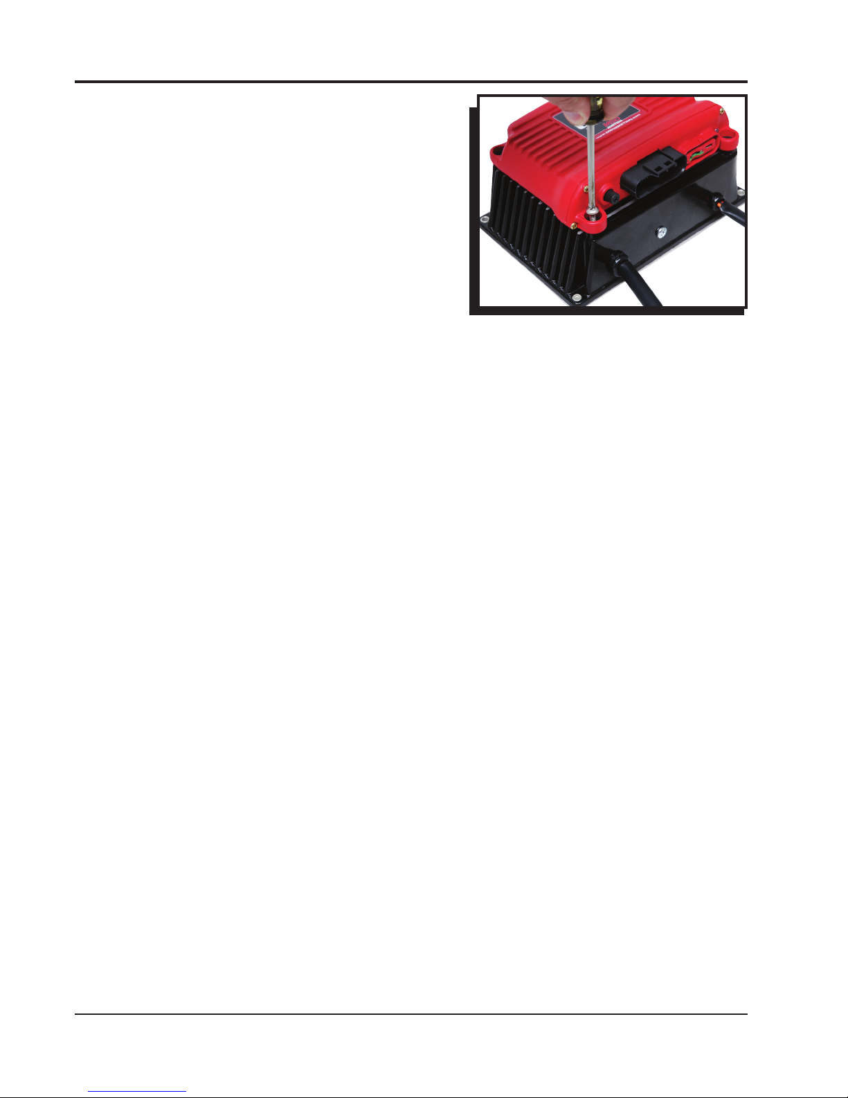
MOUNTING
The Power Grid System Controller should be mounted in a
sturdy, dry location that does not expose the unit to extreme
heat. It is designed to be mounted on top of the PN 7720
Power Grid Ignition. Be sure to mount the Power Grid System
Controller so the USB connector and Micro-SD card are
accessible. The unit comes with thread-turning (aka. Selftapping) screws that will cut into the walls of the pre-drilled
holes on the top corners of the Power Grid-7. If the Power Grid
System Controller, PN 7730 / PN 77303, is not being mounted
on top of the Power Grid-7 the unit should be secured with
the supplied hardware.
Note: Insecure or otherwise improper mounting of the unit
Figure 3 Mounting
could result in damage or failure. Always make sure
the unit is dry, avoids unnecessary excess vibration,
and is not exposed to extreme heat.
MSD VIEW
The MSD View software controls all of the functionality of the Power Grid System Controller. The following
information gives a brief explanation of each function or feature in the system as well as the settings that
control it. While using the program, hover the mouse over a Function to display a brief explanation.
When the system controller is connected to a PC via USB MSD View will automatically recognize it and load
the settings stored in it.
Note: Ensure that MSD View is installed on the PC prior to connecting the Power Grid Ignition Controller.
INSTALLATION OF THE VIEW SOFTWARE
1. Insert the installation CD Rom into the CD drive, wait up to 30 seconds, the CD will auto run, IF THIS
DOES NOT OCCUR:
Locate and open the CD Drive.
Double click on the Setup file.
2. Select “Click here to Install Version X.XX”.
3. Once loaded, your monitor will have an MSD View X.XX logo. Accept the agreement. Drive the installation
to your program files folder, press the enter key. The installation will complete, select OK.
4. A window will be opened with two aliases, double-click on the MSD View alias to launch the software.
5. Connect the system controller via USB. If the software does not recognize the controller and auto-connect,
manually select the Power Grid in the popup window and click Connect.
Note: The View Software can be downloaded from www.msdignition.com.
SAVES AND TRANSFERS
Using the Power Grid System Controller changes are in real time if the computer is linked to the ignition.
You can create and save numerous files on your PC and transfer them for testing purposes or to use for
various locations and conditions.
The following instructions will go through a general description of the use of the Power Grid System Control
following the tab system that you will see in the software.
MSD • WWW.MSDPERFORMANCE.COM • (915) 855-7123 • FAX (915) 857-3344
Page 5

INSTALLATION INSTRUCTIONS 5
PROGRAMMABLE FEATURES AND SETTINGS:
GENERAL
These are the most basic settings of the system. They will need to be set the first time the system is installed
in a vehicle.
Number of Cylinders: This tells the system the number of cylinders. Must be selected correctly for proper
timing and rev limiting.
Maximum Timing Reference: This is the advance that is set with a locked distributor or crank trigger. The
system controller will use this as its base for all timing marks and can never advance past the pre-set
point. It is critical that this advance is set properly.
Note: When using EFI the max timing reference and the main timing must be the same number.
Number of Gears: This tells the system the number of gears used in the transmission. This information can
be used a variety of ways depending on the functions and modules used in the system.
Ignition Type: Found under General Settings, this option allows a user to select between using the Power
Grid Ignition, PN 7720, or one of the MSD legacy ignitions.
DIAGNOSTIC LED INDICATOR
The LED is located on the far right side of the Power Grid Controller, next to the USB/SD Card cover. This
LED allows the user to quickly determine if; all systems are normal, data is being recorded or if there are
any active Alerts.
OFF – Unit is turned off
ORANGE for 1 Second – Power ON LED test
ORANGE for 10 Seconds – ARC Module (PN 7761) has been connected (*see notes below)
ORANGE - blinking – Data recording in process
GREEN - blinking – Input (crank pickup or Points wire) triggered; below 500 rpm, no active Alerts
RED - blinking – Input (crank pickup or Points wire) triggered; below 500 rpm, 1 or more active
Alerts
GREEN - solid – Running; above 500 rpm, no active Alerts
RED - solid – Running; above 500 rpm, 1 or more active Alertys
*NOTE: Many racing organizations (NHRA, IHRA, etc.) use an MSD Power Grid test tool that can check for
the following settings:
1. ARC Module - indicates if an ARC module (PN 7761) has been connected (Holds connection indicator
for the next 60 minutes of engine run time after the ARC codule has been disconnected)
2. Safety Limiter - the RPM that the engine will be limited to if it exceeds the Safety Run Time limit.
3. Safety Run Time - the run time, in seconds, after the Launch input (Blue wire) has been released. Activates
the Safety Limiter when timer reaches 0 seconds.
4. Part Numbers - lists the part numbers of any MSD compatible module connected to the Power Grid system.
5. Over Boost - Boost pressure ignition cut off value of the MSD Boost Controller (PN 7763). If connected.
CAMSHAFT SYNCHRONIZATION
This is used only in applications where the individual cylinder timing is going to be used. The fiber optic
connector communicates when the #1 cylinder fires. With this information, the controller knows which cylinder is being fired allowing for the individual cylinder timing capabilities. Only the MSD Fiber Optic Inductive Pickup Kit, PN 7555 will work for this system. Cam-sync’s cylinder #1 identification is also used in the
data acquisition recordings.
MSD • WWW.MSDPERFORMANCE.COM • (915) 855-7123 • FAX (915) 857-3344
Page 6

6 INSTALLATION INSTRUCTIONS
GEAR SHIFT
In the Gear Shift selection the user can set items such as launch and shift delay so that the system will not
have a false shift detected immediately after launch or a shift should there be an rpm drop for any other reason.
Launch Delay: The amount of time in seconds after the launch that the system will ignore an rpm drop to
prevent false shift detection. This can be set from 0.00 to 10.00 in .01 second increments.
Shift Delay: The amount of time in seconds after sensing a shift that the system will ignore an rpm drop to
prevent false shift detection. This can be set from 0.00 to 10.00 in .01 second increments.
1->2 Shift: By setting the rpm drop the user tells the system how to sense when the car is being shifted
during a run. The setting is controlled by a drop down list with rpm from 200 – 1,500 or can be set
to be activated by a Step Retard wire instead. The number of shifts that is shown is controlled by the
number of gears the system is set to in the Settings – General tab.
SHIFT LIGHT
Using the Shift Light controls opens a variety of options designed to help make sure the light is exactly as
desired. The shift light setting can be set by single rpm increments. In this control tab, each value can be
entered to the exact rpm desired and the light’s intensity can be adjusted so that it is visible without blinding.
The number of gears that appear on this tab will be auto-populated by the program after the number of gears
is set in the general settings. This can also be used with a relay as a transmission shifter. The maximum
current for this circuit is 3 amps.
Light Intensity: This percentage setting controls brightness of the shift light for easy use in both day and
night racing. If being used for anything other than shift light control, the intensity must be 100%.
Power-On Test: Normally set to on but can be turned off if desired. The power-on test turns the shift light on
as soon as the controller receives power to show that the circuit is complete and working.
Launch Light: The Shift Light will turn on if the engine rpm is between the launch low limit and the launch
high limit. The light will blink if rpm is above the launch high limit.
Gear 1-5: A setting can be adjusted for each individual shift. To do this enter the engine RPM that should
turn the Shift Light ON for each gear.
OUTPUT SWITCH
When the switch is activated it will supply ground to a circuit in order to turn an item on by time and/or rpm.
The circuit can maintain up to 2 continuous amps. If more than 2 amps is needed a relay is recommended,
PN 8961.
To activate or deactivate this circuit the system must see a programmed time and/or rpm setting which is
programmed in the Settings – Output. Using both On and Off values will set a window to control the switch.
The output will only be activated while within the set window and will be deactivated as soon as one or both
sides of the windows are not met. All parameters must be met for the output switch to be activated. For
example, if values are entered for both RPM On and Activation Point (timed on) then both of those values
must be reached before the switch is activated. The rpm function becomes active and the time function begins
counting after the Dark Blue launch wire is released.
Note: If using the time activation function a duration MUST be set above 0.00 or the switch will not be
activated by time.
IGNITION TIMING
The user can set the timing from 0 - 60° BTDC. However, actual timing will never advance past the maximum
timing reference nor will the timing retard more than 30° from the max timing reference. MAX and MIN timing
lines will be displayed for convenient reference in the main engine timing tab. (Those lines can be turned off
by unchecking them in the upper left column.)
Note: When using EFI the max timing reference and the main timing must be the same number.
MSD • WWW.MSDPERFORMANCE.COM • (915) 855-7123 • FAX (915) 857-3344
Page 7

INSTALLATION INSTRUCTIONS 7
Engine timing cannot exceed the maximum timing reference. In order to advance timing, the main timing
map must be set below the maximum timing reference. I.E. If the crank trigger is at 40° and the main timing
map is set to 35° there will be up to 5° of advance available.
ENGINE TIMING
Using MSD View software, an entire timing curve can be mapped. The map specifies the actual engine
timing. The Power Grid will retard the input trigger to obtain the correct engine timing. The maximum timing
reference must be set properly for correct engine timing. These maps include changes in 50 rpm increments
and timing changes down to 0.1 degrees. A maximum of 30 points can be set per map.
This map will show all engine timing maps that are drawn based on rpm values such as timing curves per
gear. The information for all of these maps is accumulative in the software. In order to edit a particular timing
curve the user must go into the proper tab per function.
Start Retard: As part of the general engine timing curve, users can specify a start retard. While each engine
responds differently, the typical recommendation for a start retard is to to pull out 10° from 0 - 600
rpm. A variety of other ideas can be applied to a start retard, including ramping timing in as engine
rpm climbs. Use of such techniques is at the discretion of the user.
GEAR CURVES
This program provides the ability to modify the timing curve for each gear. One curve can be created for each
gear, up to six, from 0 – 15,000 rpm in 0.1° increments for every 50 rpm. You can program up to 30 different
points on each Gear Curve. The number of gears shown and how a shift is detected are dependent on the
selected values in the Settings tab.
In the Ignition Timing – Gear Curves tab, an individual curve is plotted for each gear. Each change made for the
gear curves references off of the Main Timing curve are set in the Engine RPM tab, not off of the max timing
reference. Gear curves are NOT cumulative; i.e. Retarding 1° in 2nd gear does not affect 3rd gear settings.
Note: The gear curves are independent of each other. In order to make progressive changes, one gear’s
starting point must match the final timing of the previous gear’s curve. Leaving a gear curve unedited
will result in normal timing for that gear regardless of other gear curves ahead of or behind it.
INDIVIDUAL CYLINDER TIMING
Note: To control ICT an inductive pickup, PN 7555, is required.
To accomplish timing changes per cylinder the engine’s firing order must be entered first. Firing order is
programmed in the tab Ignition Timing – Individual Cylinder – Firing Order by numbering the order into the
Value column. Many common firing orders can also be imported from a database within the software; to do
so simply go to FileImport and open the “firing_order” folder where an engine description can be selected.
Similarly, if an engine uses a firing order not included in these options the settings can be exported to be
saved in the same file.
After the correct firing order is entered individual cylinder timing can be created by editing rules. Up to 10
rules can be entered to control various aspects of timing for a single cylinder at a time. Each rule has six
(6) values that can be controlled; Cylinder, Retard/Advance, Timing, From Gear, Delay, and Ramp Time. To
make a rule the first four control values must be entered, Delay and Ramp Time may be left at the default of
0 if desired. When timing is changed on an individual cylinder, in order to bring the cylinder back to original
timing an equivalent amount of timing must be used to offset (DO NOT use 0°). I.E. If cylinder two is retarded
by 3° in RULE 1, in order to put the timing back in the cylinder must be advanced in a later rule by 3°.
Cylinder: Double click this value to select the cylinder for which timing is to be altered.
Retard / Advance: Enter whether timing will be Retarded or Advanced. After using this option timing changes
will always be entered as a positive number.
Note: Engine timing cannot exceed the maximum timing reference. In order to advance timing, the main
timing map must be set below the maximum timing reference. I.E. If the crank trigger is at 40° the main
timing map is set to 35° there will be up to 5° of advance available.
MSD • WWW.MSDPERFORMANCE.COM • (915) 855-7123 • FAX (915) 857-3344
Page 8

8 INSTALLATION INSTRUCTIONS
Timing Change: Enter the amount of timing that is to be retarded or advanced. This value will always be a
positive number, regardless of whether advance or retard is desired.
From Gear: This setting determines from which gear the timing change will become active. If gear one is
selected the timing change will be active at all times unless a delay is used.
Delay: This is the time, in seconds, that will pass prior to initiating the timing change after the proper gear
change. This setting defaults to 0.0 but can be taken up to 5.0 seconds. If a timing change is desired
during an entire run, but not other times the engine is running, this setting should be entered as 0.1 sec.
Ramp Time: The amount of time it takes for the Individual Cylinder Timing to be fully engaged. During this
time the controller will ramp the timing change from the starting point to full timing.
Note: Changes made in Individual Cylinder Timing are cumulative. If a cylinder’s timing is to be altered for a
duration of time two rules must be made, one to initiate the change and another to reverse the change
at the appropriate time.
LAUNCH RETARD (TIMING BY TIME)
This function allows a user to set an engine timing curve based on the run time from launch (release of the
dark blue wire). It can be programmed from 0° to 20° in 0.1° increments. Up to 30 trace points can be set per
0.01 sec. across the available 10 seconds. When the Launch wire is active, the retard value is the placement
of the first dot. When 12 volts are removed from the Dark Blue wire the engine timing will follow the prescribed
curve added to the base timing set at the engine RPM map.
STEP RETARDS
There are five step wires that control each of the corresponding step retards. These retards can be set so
that they are not active until a specified rpm is reached even if the wire receives voltage. Using this system
a step can activate as soon as the trigger wire receives 12 volts or after the engine reaches a specific rpm
with 12 volts at the trigger wire. Once the retard is activated, timing can be changed in a single step or be
ramped in over a period of time. The retard can also be turned off in a single step or ramp after a prescribed
time after power is removed.
Step Retard Activation Wires
Step 1 Step 2 Step 3 Step 4 Step 5
Pink Violet Tan Light Green Green
Note: These wires can also be used as Gear Select Indicators. See page 5.
Note: The Step-5 wire may be used as a Spool Rev Limiter. When using this wire for a retard and not a Spool
Rev Limiter, the rev limit setting must be set above the max rev setting.
Activation through Wiring: Each step is activated by applying 12 volts to the corresponding wire. When
multiple step retards are enabled at the same time the retard amounts are added together. The
maximum retard allowed by the system is a total of 30° (including other retard amounts from a launch,
boost, gear retard, etc).
Activation through RPM: Each step retard can also be activated through rpm. In order to achieve this,
12 volts must still be applied to the corresponding step retard, and an rpm must be entered in the
respective step retard control. When 12 volts is applied, the retard will not activate until the rpm value
is reached. Note that the retard will remain active until the rpm drops back below the set value. The
step retard is added to all other retards in the system, including other active steps until it is deactivated.
Each of the five step retards has its own tab under the Ignition Timing – Step Retard tab. Within the individual
tabs there are controls for the step retard.
Timing Retard: This is the amount of timing that will be retarded while this step is active. The timing can
be adjusted in 0.01° increments.
Engine RPM: When this setting is used the engine must be above the prescribed RPM before the step
retard will be activated.
On Ramp: The amount of time it takes for the step retard to retard the full amount. During this time the
controller will ramp the timing retard from the starting point to full step retard.
MSD • WWW.MSDPERFORMANCE.COM • (915) 855-7123 • FAX (915) 857-3344
Page 9

INSTALLATION INSTRUCTIONS 9
Off Delay: This feature will set a time based delay to deactivate the step retards. The Off Delay is designed
to keep the timing retarded after the wire is deactivated. This setting defaults to 0.0 sec but can be
taken up to 5.0 sec by the user.
Off Ramp: The amount of time the system takes to turn the step retard off once power is removed from the
step wire and any delay is complete. During this time the controller will ramp the step retard out.
Note: If you prefer to activate the step retards through the activation wires alone without considering rpm the
setting for rpm should be left at the default of 0.
SHIFT RETARD
Using MSD View, a retard can be implemented momentarily to help maintain traction immediately after a
shift. To do this, simply enter the amount of timing retard desired and the length of time the retard should be
active for each shift. Whether using an rpm drop or a step retard activation wire for a trigger, as soon as the
system detects a shift it will retard the timing for the prescribed amount of time.
REV LIMITER
A variety of different rev limits can be programmed per individual vehicle needs. The actual rev limiter will
never exceed the maximum rev limiter.
Burnout Rev Limiter: This limit is activated when 12 volts are applied to the Light Blue wire. It is adjustable
from 1,000 to 15,000 rpm. Note that the Slew Rev Limiter is disabled by the Burnout Limit.
Launch Rev Limit: This limit is activated when 12 volts are applied to the Dark Blue wire. It is adjustable
from 1,000 to 15,000 rpm.
Latching: When this setting is enabled engine rpm must be below 7/8 of the launch limit setting while 12
volts is applied to the Dark Blue wire to engage the Launch Limiter. This allows clutch cars to wire
the Dark Blue wire directly to the clutch switch without the need to use a relay. If Latching is disabled,
the Launch Rev Limiter will be engaged anytime the Dark Blue wire receives 12 volts (such as during
each shift) regardless of engine rpm.
Maximum Rev Limiter: This is the overrev limit to help protect the engine from damage.
Spool/Step 5 Rev Limiter: This program gives turbo cars a fourth rev limit to help the engine spool the
turbo prior to the launch. It is active when 12 volts is applied to both the Light and Dark Blue wires
at the same time or when using the Step 5 retard wire. (The Step 5 wire can allow for activating the
Spool rev Limiter without activating the line-lock.) It is adjustable in 50 rpm increments from 1,000
to 15,000. Default is 12,000 rpm.
Safety Run Time Rev Limiter: Using two settings a safety limiter can be activated in case of incident. If for
any reason the engine is still revving after the set amount of time since the launch limiter is released,
this feature will lower the rev limit to a user specified rpm over 2 seconds. This will help anytime the
throttle is open much longer than it should be, such as a stuck throttle linkage or an accident.
Users have two options to activate the Safety Run Time countdown; the Launch limiter, or the Safety
RPM Start. In either case the Dark Blue wire must be activated so that time down can start upon
its release. Many users will activate the Safety countdown by bringing the engine up on the limiter.
Users who do not wish to use the launch rev limiter can activate the safety run time countdown by
taking the engine rpm equal or higher than the Safety RPM Start setting. This setting act only as a
countdown activator and has no rev limiting ability.
DATA ACQUISITION
The data recorder on the Power Grid System Controller comes with a 2GB micro SD card which will easily
hold more than an entire event’s worth of data. Within the settings for data acquisition on the system controller
there are four tabs that provide options for when and what data is recorded. If a new micro-SD card is needed
or wanted for any reason it is important to get a Class 6 or higher at the minimum, NOT all micro-SD cards
will work. If there is question as to whether an SD card will work test recording should be done prior to a run.
The Power Grid System Controller will also easily send the data it records to compatible Racepak data
acquisition systems. To connect the two systems simply plug the included VNet connector into an available
space on the on the Racepak system. To be compatible the user must have a Racepak Data VNet Logger
using DatLink Software v3.7.4 or higher. Default settings will send 13 channels of data to the RacePak system.
MSD • WWW.MSDPERFORMANCE.COM • (915) 855-7123 • FAX (915) 857-3344
Page 10

10 INSTALLATION INSTRUCTIONS
Settings:
This tab has two possible adjustments. The first setting allows a user to turn the data recording off, if
desired. The second control tells the system what to do if the SD card is full. This setting allows the
system to either stop recording or begin to write over data with the lowest recording name. By default
the system is on and will overwrite once the memory is full.
Channels:
Each available data trace within the PN 7730 / PN 77303 is listed in this tab. Each trace can be
disabled individually in order to remove unneeded traces and generate smaller files. The Ignition In
channel and the Ignition Out channel are high resolution and they generate the most amount of data
at high engine rpm.
Start Recording:
The settings here tell the controller when to start recording data so that only useful information is
stored. The recorder can be started by RPM alone or by adding a function to the RPM. For example,
the default setting starts recording as soon as the Launch Rev wire is activated and the RPM is above
3,000.
Stop Recording:
In this tab the user controls when to stop recording. The recording can be stopped by reaching a lower
rpm limit or a trigger such as a step wire signal. When stopping recording only one of these setting
values must be triggered. There is also a setting to keep recording for some time after the trigger to
ensure that all useful data is captured. Finally, there is a user set maximum recording time limit to
ensure recording stops even if the system is not triggered for any reason.
-
BLACK
+
ORANGE
YELLOW - SHIFT LIGHT
GRAY - TACH
BRN/WHITE - RPM/TIME SWITCH
LT. BLUE - BURN OUT
BLUE - LAUNCH
PINK - STEP 1
VIOLET - STEP 2
TAN - STEP 3
LT. GREEN - STEP 4
GREEN - STEP 5
SWITCHED IGNITION 12V
WHITE - POINTS IN
-
+
ORANGE
BLACK
BATTERY
BATTERY
SUPPLIED JUMPER
WHITE
ORANGE
RED
V-NET
CABLE
LEGACY IGNITION
BLACK
MSD
CAN
GREEN
VIOLET
GREEN
VIOLET
Figure 4 Wiring the Power Grid Controller to MSD 8-Plus.
MSD • WWW.MSDPERFORMANCE.COM • (915) 855-7123 • FAX (915) 857-3344
Page 11

INSTALLATION INSTRUCTIONS 11
V
CHASSIS
GROUND
IGNITION
MSD RPM
RECEPTICAL
VIOLET
BLACKRED
WHITE
TO GROUND
ON CYLINDER HEAD
LEGACY
IGNITION
RED
NOT USED
ORANGE
V-NET
CABLE
BLACK
BATTERY
POSITIVE
+
-
BATTERY
NEGATIVE
YELLOW - SHIFT LIGHT
GRAY - TACH
BRN/WHITE - RPM/TIME SWITCH
LT. BLUE - BURN OUT
BLUE - LAUNCH
WHITE - POINTS IN (NOT USED)
PINK - STEP 1
VIOLET - STEP 2
TAN - STEP 3
LT. GREEN - STEP 4
GREEN - STEP 5
RED - SWITCHWED IGNITION 12
NOT USED
MSD
CAN
GREEN
VIOLET
GREEN
VIOLET
Figure 5 Wiring the Power Grid Controller to Pro-Mag.
MSD • WWW.MSDPERFORMANCE.COM • (915) 855-7123 • FAX (915) 857-3344
Page 12

12 INSTALLATION INSTRUCTIONS
PN 8253
-
BLACK
+
ORANGE
TACH
NOT
USED
IGNITION
Multiple
Spark
Discharge
V-NET
CABLE
AUTOTRONIC CONTROLS CORPORATION
PART NO.
SERIAL NO..
MSD RPM
RECEPTICAL
RED
BLACK
ORANGE BLACK
RED
WHITE
LEGACY IGNITION
INDICATES CONNECTION
BATTERY
POSITIVE
+
-
BATTERY
NEGATIVE
MSD
CAN
Figure 6 Wiring the Power Grid Controller to MSD 6AL.
GREEN
VIOLET
GREEN
VIOLET
YELLOW - SHIFT LIGHT
GRAY - TACH
BRN/WHITE - RPM/TIME SWITCH
LT. BLUE - BURN OUT
BLUE - LAUNCH
WHITE - POINTS IN (NOT USED)
PINK - STEP 1
VIOLET - STEP 2
TAN - STEP 3
LT. GREEN - STEP 4
GREEN - STEP 5
SWITCHED IGNITION 12V
ALERTS:
There are a variety of alerts that can arise in the Power Grid System Controller. If there are any errors or
other causes of alert, the LED on the front of the controller will show red. Any time the red light shows the
alerts should be checked so that errors can be corrected. By default, a pop-up box will appear as soon as
an alert is registered. The pop-up window has a check box to disable the pop-ups if desired.
The alerts window can also be opened manually two ways. On the bottom bar of the program window pane
there is an alert counter that will show the number of alerts present. A single click on the alert counter at
any time will open the alert window. The alert window can also be opened by going to the View menu on
the task bar.
MSD • WWW.MSDPERFORMANCE.COM • (915) 855-7123 • FAX (915) 857-3344
Page 13

INSTALLATION INSTRUCTIONS 13
Alert Alert
ID Text Alert Activation Conditions Description
1 Low Battery Voltage EngineRPM > 500 AND Vbatt < This alert activates when there is low battery voltage
9.0 for 5 seconds with engine RPM. Make sure the 7730/77303 is properly
connected to battery voltage.
2 High Battery Voltage Vbatt > 18.0 This alert activates when there is high battery voltage.
Make sure the 7730/77303 is properly connected to battery voltage
3 Crank Sensor This alert activates due to weak crank sensor signal. Make sure
Voltage Low
5 No CAM Sync Engine RPM > 300 AND This alert activates when individual cylinder timing has been
6 12V Output Current > 3A for 10 ms This alert activates when there is too much load on
Sh utdown the 12V bus that is used to power accessory modules. Make sure
13 Low SDcard Storage This alert activiates when an SDCard is present and there is
14 SDcard Initialization This alert activates when the 7730/77303 cannot initialize the
Error
15 SDcard Write Error This alert activates when the 7730/77303 is unable to write to
16 SDcard Read Error This alert activates when the 7730/77303 is unable to read the
17 SDcard Missing SDcard not present AND data acquisition enabled AND Engine
18 Data Acquisition DAQ memory buffer overflow This alert activates if the interal data acquisition memory buffer
Memory Overflow
19 12V Output Overcurrent Current > 2A for 10 ms This alert occurs when there is too much load on the 12V bus
20 EEPROM CRC Error This alert occurs if the 7730/77303 is unable to recover
21 EEPROM Write Error This alert occurs if the 7730/77303 is unable to write
22 Data Acquisition This alert activates if the internal data acquisition memory
Memory Protection
Weak Crank Sensor
Individual Cylinder Timing Rule
Enabled AND no CAM Sync pulse
detected
SDcard present AND SDCard Free
Storage < 100 MB
SDcard present AND Error
Initializing SDCard
SDcard present AND Error
reading to SDcard
SDcard present AND Error
writing to SDcard
SDcard not present AND
data acquisition enabled AND
EngineRPM > 0
Unable to read MFF data at startup
after 3 attempts
Unable to write any data to
EEPROM after 3 attempts
DAQ memory buffer reaches
90% utilization
the crank sensor is properly located according to the installation
instructions.
configured and no optical CAM sync signal is detected. Make
sure the optical CAM sync cable is properly connected to the
7730/77303.
there are no short circuits and the 12V bus is not overloaded.
less than 100 MB of storage available on the card. Remove
some data from the SDCard to remove this alert.
SDCard. Make sure you are using the MSD factory supplied
SDCard.
the SDCard. Make sure you are using the MSD factory supplied
SDCard.
SDCard. Make sure you are using the MSD factory supplied
SDCard.
is running.
overflows. This will cause a recording to end prematurely. Try
deactivating some data acquisition channels. Make sure you
are using the MSD factory supplied SDCard.
that is used to power accessory modules. Make sure the 12V
bus is not overloaded.
configuration data from its internal EEPROM memory. The
7730/77303 will attempt to recover a back-up stored in its
internal Flash memory. Verify your configuration settings are
correct. If this error occurs frequently, contact MSD tech support
for an RMA.
data to its internal EEPROM memory. If this error occurs
frequently, contact MSD tech support.
buffer reaches a critical limit. This will cause some data
acquisition channels to be automatically disabled. Try
deactivating some data acquisition channels. Make sure
you are using the MSD factory supplied SDCard.
MSD • WWW.MSDPERFORMANCE.COM • (915) 855-7123 • FAX (915) 857-3344
Page 14

14 INSTALLATION INSTRUCTIONS
TECH NOTES
_________________________________________________________________________________________________________________________
_________________________________________________________________________________________________________________________
_________________________________________________________________________________________________________________________
_________________________________________________________________________________________________________________________
_________________________________________________________________________________________________________________________
_________________________________________________________________________________________________________________________
_________________________________________________________________________________________________________________________
_________________________________________________________________________________________________________________________
_________________________________________________________________________________________________________________________
_________________________________________________________________________________________________________________________
_________________________________________________________________________________________________________________________
_________________________________________________________________________________________________________________________
_________________________________________________________________________________________________________________________
_________________________________________________________________________________________________________________________
_________________________________________________________________________________________________________________________
_________________________________________________________________________________________________________________________
_________________________________________________________________________________________________________________________
_________________________________________________________________________________________________________________________
_________________________________________________________________________________________________________________________
_________________________________________________________________________________________________________________________
_________________________________________________________________________________________________________________________
_________________________________________________________________________________________________________________________
_________________________________________________________________________________________________________________________
_________________________________________________________________________________________________________________________
_________________________________________________________________________________________________________________________
_________________________________________________________________________________________________________________________
_________________________________________________________________________________________________________________________
_________________________________________________________________________________________________________________________
_________________________________________________________________________________________________________________________
_________________________________________________________________________________________________________________________
_________________________________________________________________________________________________________________________
_________________________________________________________________________________________________________________________
_________________________________________________________________________________________________________________________
_________________________________________________________________________________________________________________________
_________________________________________________________________________________________________________________________
_________________________________________________________________________________________________________________________
_________________________________________________________________________________________________________________________
_________________________________________________________________________________________________________________________
MSD • WWW.MSDPERFORMANCE.COM • (915) 855-7123 • FAX (915) 857-3344
Page 15

INSTALLATION INSTRUCTIONS 15
TECH NOTES
_________________________________________________________________________________________________________________________
_________________________________________________________________________________________________________________________
_________________________________________________________________________________________________________________________
_________________________________________________________________________________________________________________________
_________________________________________________________________________________________________________________________
_________________________________________________________________________________________________________________________
_________________________________________________________________________________________________________________________
_________________________________________________________________________________________________________________________
_________________________________________________________________________________________________________________________
_________________________________________________________________________________________________________________________
_________________________________________________________________________________________________________________________
_________________________________________________________________________________________________________________________
_________________________________________________________________________________________________________________________
_________________________________________________________________________________________________________________________
_________________________________________________________________________________________________________________________
_________________________________________________________________________________________________________________________
_________________________________________________________________________________________________________________________
_________________________________________________________________________________________________________________________
_________________________________________________________________________________________________________________________
_________________________________________________________________________________________________________________________
_________________________________________________________________________________________________________________________
_________________________________________________________________________________________________________________________
_________________________________________________________________________________________________________________________
_________________________________________________________________________________________________________________________
_________________________________________________________________________________________________________________________
_________________________________________________________________________________________________________________________
_________________________________________________________________________________________________________________________
_________________________________________________________________________________________________________________________
_________________________________________________________________________________________________________________________
_________________________________________________________________________________________________________________________
_________________________________________________________________________________________________________________________
_________________________________________________________________________________________________________________________
_________________________________________________________________________________________________________________________
_________________________________________________________________________________________________________________________
_________________________________________________________________________________________________________________________
_________________________________________________________________________________________________________________________
_________________________________________________________________________________________________________________________
_________________________________________________________________________________________________________________________
MSD • WWW.MSDPERFORMANCE.COM • (915) 855-7123 • FAX (915) 857-3344
Page 16

TECH NOTES
_________________________________________________________________________________________________________________________
_________________________________________________________________________________________________________________________
_________________________________________________________________________________________________________________________
_________________________________________________________________________________________________________________________
_________________________________________________________________________________________________________________________
_________________________________________________________________________________________________________________________
_________________________________________________________________________________________________________________________
_________________________________________________________________________________________________________________________
_________________________________________________________________________________________________________________________
_________________________________________________________________________________________________________________________
_________________________________________________________________________________________________________________________
_________________________________________________________________________________________________________________________
_________________________________________________________________________________________________________________________
_________________________________________________________________________________________________________________________
_________________________________________________________________________________________________________________________
_________________________________________________________________________________________________________________________
_________________________________________________________________________________________________________________________
_________________________________________________________________________________________________________________________
Service
In case of malfunction, this MSD component will be repaired free of charge according to the terms of the warranty.
When returning MSD components for warranty service, Proof of Purchase must be supplied for verification. After
the warranty period has expired, repair service is based on a minimum and maximum fee.
All returns must have a Return Material Authorization (RMA) number issued to them before
being returned. To obtain an RMA number please contact MSD Customer Service at 1 (888) MSD-7859 or
visit our website at www.msdperformance.com/rma to automatically obtain a number and shipping information.
When returning the unit for repair, leave all wires at the length in which you have them installed. Be sure to include
a detailed account of any problems experienced, and what components and accessories are installed on the vehicle.
The repaired unit will be returned as soon as possible using Ground shipping methods (ground shipping is covered
by warranty). For more information, call MSD at (915) 855-7123. MSD technicians are available from 7:00 a.m. to 5:00
p.m. Monday - Friday (mountain time).
Limited Warranty
MSD warrants this product to be free from defects in material and workmanship under its intended normal use*,
when properly installed and purchased from an authorized MSD dealer, for a period of one year from the date of the
original purchase. This warranty is void for any products purchased through auction websites. If found to be defective
as mentioned above, it will be repaired or replaced at the option of MSD. Any item that is covered under this warranty
will be returned free of charge using Ground shipping methods.
This shall constitute the sole remedy of the purchaser and the sole liability of MSD. To the extent permitted by law,
the foregoing is exclusive and in lieu of all other warranties or representation whether expressed or implied, including
any implied warranty of merchantability or fitness. In no event shall MSD or its suppliers be liable for special or
consequential damages.
*Intended normal use means that this item is being used as was originally intended and for the original application
as sold by MSD. Any modifications to this item or if it is used on an application other than what MSD markets the
product, the warranty will be void. It is the sole responsibility of the customer to determine that this item will work for
the application they are intending. MSD will accept no liability for custom applications.
MSD • WWW.MSDPERFORMANCE.COM • (915) 857-5200 • FAX (915) 857-3344
FRM 30299 Revised 04/16
© 2016 MSD LLC
 Loading...