

MSD
Programmable Shift Controller
PN 75591
WARNING: During installation, disconnect the battery cables. When disconnecting, always
remove the Negative cable first and install it last.
Parts Included:
1 – Shift Controller 8 – #10 Screws 10 – Butt Splices
1 – Pro-Data+ Software 4 – #10 Nuts 2 – Ring Terminals
1 – 9-Pin Harness, 10-Feet 4 – #10 Washers
2 – Deutsch Terminated Harnesses 1 – 1-Pin Harness
Note: Solid core spark plug wires cannot be used with this controller.
The MSD Programmable Shift Controller allows you to
program different rpm points to trigger the shift solenoids.
Any transmission configuration may be used up to a six
speed trans. Programming the rpm and options of the Shift
Controller can be done with MSD’s Hand Held Monitor, PN
7550, or with the MSD Pro-Data+ Software on a Windows
based PC.
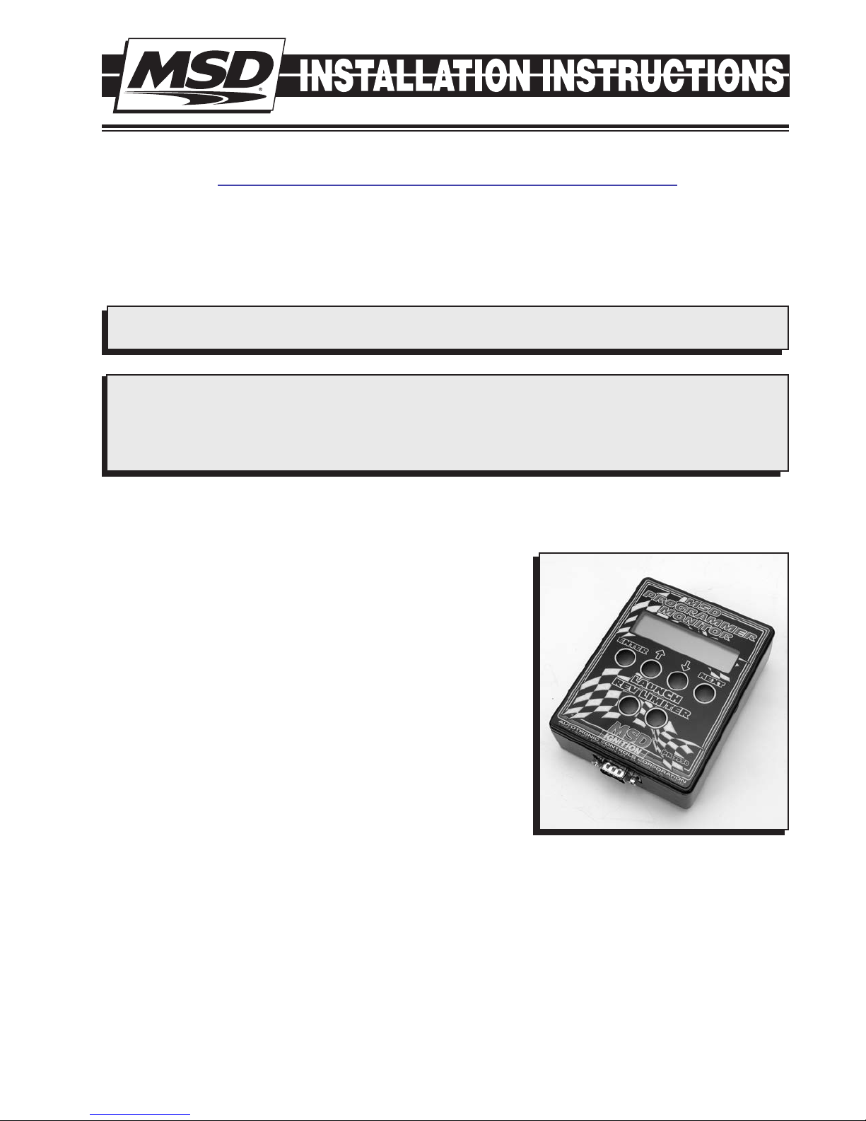
The optional Hand Held Programmer/Monitor, PN 7550,
connects through the 9-pin connector on the Control and
features an LCD display that allows you to walk through the
programs as well as monitor the engine’s rpm, the current
gear, alerts and more (Figure 1).
There is also a computer disk supplied with the MSD
ProData+ software. This software is for PCs running windows
95, 98 or NT. All of the adjustable parameters can be reviewed
and set, then uploaded to the Controller. More information
on using this software begins on page 5.
Figure 1 Hand Held Programmer, PN 7550.

2 INSTALLATION INSTRUCTIONS
PROGRAMMABLE FEATURES
Application
The number of cylinders and number of gears must be programmed. The Cylinder Count (CylCnt)
default is 8-cylinders, and can be programmed for 4 or 6-cylinders. The Transmission needs to
be configured as well. The default is 6-gears and can be programmed for 2, 3, 4, 5 and 6-gear
transmissions on the (LastGear) menu.
Gear Solenoids
There are different shift solenoids available and will need to be selected. The default is a SequenceOn which is activated with 12 volts and remains on. There is also a Pulsed solenoid that receives a
Pulsed signal to activate the solenoid. The time of the Pulse signal is also adjustable from 0.100 to
2.5 seconds in 0.010 increments (The solenoid manufacturer should specify a pulse time).
Shift RPM
The rpm for each gear change needs to be programmed from the Gear Select (GearSel) menu. The
rpm can be programmed from 1,000 to 12,500 rpm in 100 rpm increments.
Launch Wire Activation
This program (LaunchIn) selects the input signal. The Dark Blue wire is the Set/Reset wire and can
be activated by either being grounded or when connected to 12 volts. The default is the ground
setting.
Note:
To test the Dark Blue wire's operation, the engine must be running so the Shift Controller
receives a trigger signal. MSD offers an optional tester, PN 8998, that allows you to test the
Controller without the engine running. See page 6.
Shift Inhibit
This program is programmable from 300 to 600 milliseconds. It will inhibit or delay the next shift from
occurring by the amount of time programmed. This (Inhibit) is used during the launch or in cases of
wheel spin. The default is 300 milliseconds.
Display Default Data Low-High (increments)
Cylcnt $ 8 4/6/8
ShiftLt1 ###00 Rpm 7,000 1,000-12,500 (100)
ShiftLt2 ###00 Rpm 7,500 1,000-12,500 (100)
ShiftLt3 ###00 Rpm 8,000 1,000-12,500 (100)
ShiftLt4 ###00 Rpm 8,500 1,000-12,500 (100)
LastGear # 6 2-6 (1)
LaunchRst Sw $$$ Gnd Gnd/Pwr
OutSel $$$$$ SeqOn SeqOn/Pulse
PulseTime #.## .50 .10-2.50 Sec (.01)
Inhibit ### 300 300-600 ms (10)
AlertsPerScan # 0 0-1 (1)
Figure 2 Default Setting Chart.

INSTALLATION INSTRUCTIONS 3
LEDS
There are six LEDs on the end panel of the Controller. The Red status LED will be on steady when the
unit is turned On. Once the launch reset wire is activated (Dark Blue) this LED will blink rapidly (this
is handy during clutch setup). When the launch reset wire is deactivated the status LED will turn off.
The Green LEDs indicate each shift. Each LED will light up as the gearshift is activated. In SequenceOn mode they stay on until the power is turned Off or the Launch Reset wire is activated again. In
Pulse mode each LED will blink for the gearshift.
If there is a shorted solenoid or an over heated solenoid
driver the status LED will blink a fault code to indicate
which solenoid output is at fault. The fault codes will
continue until the Launch Reset is active or the power
is turned off. The blink codes are:
Two blinks Shift 1 output
Three blinks Shift 2 output
Four blinks Shift 3 output
Five blinks Shift 4 output
Six blinks Shift 5 output
Figure 3 Shift LEDs.
WIRING
Heavy Red To Battery positive (+).
Heavy Black
Violet To 12 volts at the ignition switch.
Dark Blue
Light Blue Shift Override input wire to +12 volts momentary switch.
Pink 12 volt activation output for RPM Module Selectors.
Gray Tach input, 12 volt signal from ignition.
Orange/Yellow
Fuse
Shift Solenoid Wires
Red Wires These five wires provide the positive12 volts to each shift solenoid.
Brown Coil negative (-), Solenoid 1.
White Coil negative (-), Solenoid 2.
Orange
Yellow Coil negative (-), Solenoid 4.
Dark Green Coil negative (-), Solenoid 5.
Red/Green This wire provides the positive 12 volts to the Shift Light. Protected by
To Battery negative (-) or other good ground.
Launch Reset input wire to +12 volts or ground.
This is the signal wire for a shift light.
Mini Blade, 20 Amp fuse.
They are protected by a 20 Amp fuse.
Coil negative (-), Solenoid 3
20 Amp fuse.

4 INSTALLATION INSTRUCTIONS
IGNITION
TM
OR
Hand Held
Programmer
PN 7550
or Laptop with
MSD Pro-Data+
Software
AUTOTRONIC CONTROLS CORPORA
TION
ENTER
NEXT
LAUNCH
REV LIMITER
P
N
75
5
0
ENTER
NEXT
LAUNCH
REV LIMITER
P
N
75
5
0
TM
1490 HENR
Y BRENNAN DR., EL P
ASO, TX 79936
Shift Solenoids
RED
RED
RED
RED
RED
/GREEN
BROWN
WHITE
ORANGE
YELLOW
BATTERY
12 Volts
CLUTCH SWITCH
OR
TRANS BRAKE
ORANGE/YELLOW
DARK BLUE
(RESET)
LIGHT BLUE
(SHIFT OVERRIDE)
RED
DK GREEN
MSD LED
SHIFT LIGHT
PN 7552
VIOLET
12 Volts
IGNITION
SWITCH
TACH
INPUT
GRAY
12
3
4
5
PROGRAMMABLE
SHIFT CONTROLLER
TO IGNITION
20 AMP
FUSE
LEDS
MODULE SELECTOR
MODULE 2 MODULE 1
PN 8739
AUTOTRONIC CONTROLS CORPORATION
1490 HENRY BRENNAN DR, EL PASO, TX 79936
TM
BLACK
GROUND
PINKRED
DARK BLUE IS
PROGRAMMABLE FOR
GROUND OR 12VOLTS
Note: NHRA's rules only allow one wire to be connected to the Trans Brake. Connect the MSD Dark
Blue (reset) to the Trans Brake Switch. The Two or Three Step Activation wire can connect to the
Pink wire of PN 75591.
Figure 4 Wiring the Programmable Shift Controller.

INSTALLATION INSTRUCTIONS 5
MENUS
Monitor Status
Cyl Cnt Shift*
Stat 1 Scan
ScanTime 1Sec
1 TO 9
ScanTime 1SEC
Rpm 12500
S
H
Cylcnt 8
4,6,8
ShiftGears
ShiftRpm
*
LastGear6
Inhibit 300ms
*
300 TO 600
GearSel1
Rpm 12500
1000 TO 12,500
Launch Alerts*
AlertsPer
LaunchRst
2 TO 6
Gearsolenoid
PulseTime
*
Gearsolenoid
Out_SeqOn
Out_SeqOn
Out_Pulse
PulseTime
Sec#.#
0.10 Sec to 2.50 Sec
Sw_Gnd
Sw_Gnd
Sw_Pwr
Alerts
2 Out1
3 Out2
4 Out3
5 Out4
6 Out5
Monitor List
1 ScanTime 1Sec
2 ShiftLt OFF
3 Rpm 12500
4 Gear 1
5 LaunchRst OFF
6 OverRide OFF
Stats List
Same as Monitor
list at left
PRO-DATA+ PROGRAMMING INSTRUCTIONS
Installing the Software
1. Insert the installation CD.
2. In Windows click Start then select Run.
3. In the box type A:\Setup then press Enter.
4. Follow the on-screen instructions.
5. At this point there should be two MSD icons on your desktop.
6. Select the one that says MSD Graph View.
7. In the upper left corner of the screen select File.
8. Select the folder 7559.
9. Select the file that says 7559vXX.IGN (XX means the latest version such as 02).
10. Click on Open.
Saves and Transfers
Whenever a change is made to a program it either must be saved to your PC as part of the file you
are programming or it must be Saved/Transferred to the MSD Controller. The software gives you the
choice of automatically transferring the change to the MSD or the PC.
Save to MSD: By saving the change right to the MSD, the new change is automatically put into the
Controller.
Save to PC: This saves the changes on your PC screen only. The information still must be transferred
to the MSD before it becomes active or saved to a file.
Tachometer
The tachometer on the monitor will show real time rpm when the engine is running with the laptop
connected.
Figure 5 Monitor Screen Menu.

6 INSTALLATION INSTRUCTIONS
IGNITION
TM
OR
Hand Held
Programmer
PN 7550
or Laptop with
MSD Pro-Data+
Software
AUTOTRONIC CONTROLS CORPORA
TION
ENTER
NEXT
LAUNCH
REV LIMITER
P
N
7
5
5
0
ENTER
NEXT
LAUNCH
REV LIMITER
P
N
7
5
5
0
TM
1490 HENR
Y BRENNAN DR., EL P
ASO, TX 79936
Shift Solenoids
RED
RED
RED
RED
RED
/GREEN
BROWN
WHITE
ORANGE
YELLOW
BATTERY
12 Volts
CLUTCH SWITCH
OR
TRANS BRAKE
ORANGE/YELLOW
DARK BLUE
(RESET)
LIGHT BLUE
(SHIFT OVERRIDE)
RED
DK GREEN
MSD LED
SHIFT LIGHT
PN 7552
VIOLET
12 Volts
IGNITION
SWITCH
TACH
INPUT
GRAY
12
3
4
5
PROGRAMMABLE
SHIFT CONTROLLER
20 AMP
FUSE
LEDS
MODULE SELECTOR
MODULE 2 MODULE 1
PN 8739
AUTOTRONIC CONTROLS CORPORATION
1490 HENRY BRENNAN DR, EL PASO, TX 79936
TM
BLACK
GROUND
PINKRED
DARK BLUE IS
PROGRAMMABLE FOR
GROUND OR 12VOLTS
RED
TESTER, PN 8998
WHITE
GRAY
BLACK
Figure 6 Wiring the Programmable Shift Controller.
Testing the Programmable Shift Controller with optional Ignition Tester, PN 8998.
1. Connect the Tester's Red wire to 12 volts and Black wire to ground.
2. Connect the Tester's White wire to the Gray tach input wire of the Shift Controller.
3. Reset the Dark Blue wire to start test.
4. Accelerate the Ignition Tester by rotating the RPM knob to the 1st gear shift point then drop the
RPM. Repeat and check accuracy of desired RPM through all gears.
 Loading...