

Programmable Digital-7 Plus
PN 7531
ONLINE PRODUCT REGISTRATION: Register your MSD product online and you’ll be entered
in our monthly 8.5mm Super Conductor Spark Plug Wire give-away! Registering your product
will help if there is ever a warranty issue with your product and helps the MSD R&D team create
new products that you ask for! Go to www.msdperformance.com/registration.
Parts Included:
1 - Ignition Control, PN 7531
1 - MSD Pro-Data+ CD Rom
4 - Vibration Mounts & Screws
1 - Shielded Cam Sync Harness
1 - 9-Pin Computer Harness
Accessories
Hand Held Monitor, PN 7550
Inductive Cam Sync Pickup Kit, PN 7555
Non-Magnetic Cam Sync Pickup Kit,
PN 2346
Manual Launch RPM Control, PN 7551
Digital Shift Light, PN 7542
WARNING: During installation, disconnect the battery cables. When disconnecting, always remove
the Negative cable first and install it last.
1 - Mag Pickup Harness, PN 8860
1 - 12-Pin Harness
1 - Coil Harness
1 - Power Lead Harness
MAP Sensor, see page 9
Replacement Harness, PN 8855
Single Pole/Single Throw Relay, PN 8961
Double Pole/Double Throw Relay, PN 8960
Note: Solid core spark plug wires cannot be used with an MSD Ignition Control.
OPERATION
DIGITAL OPERATION
The MSD Programmable Digital-7 Plus uses a high speed RISC microcontroller to control the ignition’s output
while constantly analyzing the various inputs such as supply voltage, trigger signals and rpm. The high speed
controller can make extremely quick compensations to the output voltage, multiple spark series, timing and rpm
limits while maintaining accurate timing signals to within +/- 0.1° and +/- 10 rpm. The circuits and controller of
the ignition have been thoroughly debounced and suppressed to create protection against Electro Magnetic
Interference (EMI).
CAPACITIVE DISCHARGE
The MSD features a capacitive discharge ignition design. The majority of stock ignition systems are inductive ignitions.
In an inductive ignition, the coil must store energy and step up the supplied voltage to maximum strength between
each firing. At higher rpm, since there is less time to charge the coil to full capacity, the secondary voltage falls short
of reaching its maximum energy level which results in a loss of power or top end miss.
The MSD Ignition features a capacitor which is quickly charged to 520 - 535 volts and stores its energy until the
ignition is triggered. With the CD design, the energy sent to the coil is always at maximum power even at high rpm.
MULTIPLE SPARKS
The MSD produces full power multiple sparks for each firing of a plug. The number of multiple sparks that occur
decreases as rpm increases, however the spark series always lasts for 21° of crankshaft rotation. Above 3,300 rpm
there is simply not enough “time” to fire the spark plug more than once, so there is only one powerful spark.
M S D • W W W . M S D P E R F O R M A N C E . C O M • ( 9 1 5 ) 8 5 7 - 5 2 0 0 • F A X ( 9 1 5 ) 8 5 7 - 3 3 4 4
2 INSTALLATION INSTRUCTIONS
PROTECTION
The MSD Programmable Digital-7 Plus has a built in reverse polarity protection circuit. This will protect the ignition
in the event of wrong connections. It will also shut off for protection from a surge in power. The ignition will still
operate once the surge or polarity is corrected.
LED INDICATOR
There is an LED that monitors the status of the Ignition. The LED will verify trigger inputs and will flash trouble
codes such as a Code 2-blinks for No Cam Sync or Code 3-blinks for Low Battery supply voltage.
CAMSHAFT SYNCHRONIZATION
This is used only in applications where the individual cylinder timing is going to be used. The 2-pin connector
with a Light Blue and Light Green wire connects to a sensor that is used to synchronize or alert the Ignition as to
when the number one cylinder is going to be triggered. With this information, the Ignition knows which cylinder
is being fired allowing for the individual cylinder timing capabilities. MSD offers two kits to use for sync signals:
Universal Cam Sync Sensor, PN 2346 and a Fiber Optic Inductive Pickup Kit, PN 7555.
WIRING
Heavy
Ignition supply wire. Connects to battery positive (+) terminal or battery junction.
Red
Note: Do not connect to the alternator.
Heavy
Ignition supply Ground wire. Connect to battery negative (-) terminal or engine block.
Black
Red On/Off switch wiring. Connects to a switched 12 volt source.
Primary Coil Leads
Orange Connects to the coil positive (+) terminal. This is the only wire that makes contact to
the coil positive terminal.
Black Connects to the coil negative (-) terminal. This is the only wire that makes contact to
the coil negative terminal.
WARNING: High voltage is present at the coil primary terminals. Do not touch the coil or
connect test equipment to the terminals while the engine is running or cranking.
Trigger Wires
Violet/ Magnetic pickup, 2-pin connector. Plugs into an MSD Distributor or Crank Trigger
pickup. Violet is positive, Green is negative. Note: When this connector is used, the
Green
White wire is not connected.
2-Pin
White Trigger input for electronic ignition amplifiers, an ECU’s trigger or points.
Note: When this wire is used, the magnetic pickup wire is not connected.
Tach Output
Gray Tach output. This wire will provide the same 12 volt square wave tach signal as the
tach terminal on the side of the unit.
M S D • W W W . M S D P E R F O R M A N C E . C O M • ( 9 1 5 ) 8 5 7 - 5 2 0 0 • F A X ( 9 1 5 ) 8 5 7 - 3 3 4 4

INSTALLATION INSTRUCTIONS 3
Accessories
Dark Blue This wire activates the Launch Rev Limit and is the main reset wire for several features of the
Ignition. When 12 volts are applied to this wire it will activate the Launch Rev Limit. It also resets
the shift light and gear indicator to first gear. It also will select the Launch Retard value and Gear
1 curve. When 12 volts is removed, the Launch Ramp begins as does the Gear 1 curve.
When12 volts are applied the Slew Rate Rev limit will be disabled as well as the Timed Rev Limit
curve. When 12 volts are removed the Launch History begins recording.
Light Blue Burnout Rev Limit. When 12 volts are applied the Burnout Rev Limit is active. This disables the
Acquisition function and Slew Rate Rev Limits and overrides other rev limits. It also resets the
Acquisition Record function.
It is recommended to have this wire switched from an outside source, such as the crew chief before
the burnout and while staging the car.
Spool-Up When the Dark Blue and Light Blue wires are applied to 12 volts at the same time, a fourth rev
Limit
These three wires can be used as Retard Stage Activation and/or as a gear select wire.
Pink Step1 retard enabled with +12 volt input and above Step1 Rpm value and Gear 2 Select.
limit is activated. This limit is to spool up a turbo during the burnout. When both the Dark Blue
and Light Blue RevLimit wires are at +12 volts then the Spool RevLimit is active.
Retard Stage Wires or Gear Select
Violet Step2 retard enabled with +12 volt input and above Step2 Rpm value and Gear 3 Select.
Tan Step3 retard enabled with +12 volt input and above Step3 Rpm value and Gear 4 Select.
Note: When activated at the same time, these retard stages are added together. They are also
added with any Gear Retard Curve or Boost Retard values as well. Maximum retard is 30°.
Yellow Shift Light output wire. It can handle up to 3 amps continuous to ground when enabled.
Brown/White RPM/Time/Pressure switch output wire. It can switch up to 3 amps continuous to ground
when enabled.
Yellow/Yellow Output for data acquisition or fuel controls. Note, only two wires are used.
3-Pin Connector, MAP Sensor
Connector Connects to an external MAP or gauge pressure sensor.
Brown/Violet +5 volt supply
Brown/Yellow Ground
Dark Brown Map Signal
Cam Synchronization
Fiber Optic This input requires the PN 7555 Inductive Sync Pickup. When this input is used, the 2-pin con-
nector is not. Note: If this input is not used, the plug or a cover should be installed.
2-Pin Connector
Lt Blue/ This 2-pin plug connects to Cam Sync Sensor, PN 2346, to indicate when cylinder number
Lt Green
M S D • W W W . M S D P E R F O R M A N C E . C O M • ( 9 1 5 ) 8 5 7 - 5 2 0 0 • F A X ( 9 1 5 ) 8 5 7 - 3 3 4 4
one is firing. Note: When used, the fiber optic connector is not used and must be covered.
4 INSTALLATION INSTRUCTIONS
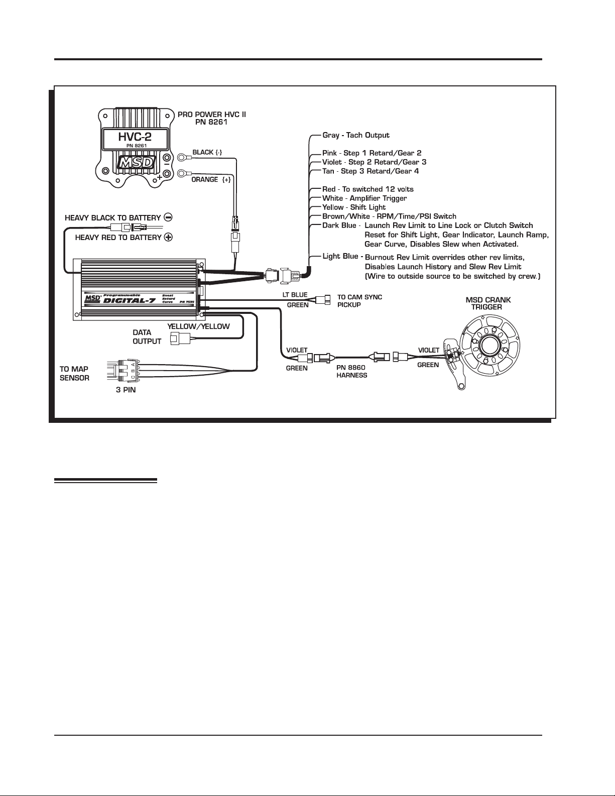
Figure 1 Wiring the Programmable Digital-7 Plus Ignition.
PRO-DATA+
INSTALLATION OF THE PRO-DATA+ SOFTWARE
1. Insert the installation CD Rom into the CD drive, wait up to 30 seconds, the CD will auto run, IF
THIS DOES NOT OCCUR:
Locate and open the CD Drive.
Double click on the autorun.exe file.
2. Select “Click here to Install Version X.XX”.
3. Once loaded, your monitor will have an MSD Pro-Data Plus X.XX logo. Accept the agreement.
Drive the installation to your program files folder, press the enter key. The installation will complete,
select OK.
4. A window will be opened with two aliases, double-click on the MSD GraphView alias to launch
the software. In the GraphView window, drag down on file and open. This will display a listing of
different part number folders. Open the 7531 folder and select your version. Double clicking the
version will launch the Pro-Data+ software for the Programmable Digital-7 Plus Ignition.
SAVES AND TRANSFERS
Whenever a change is made to a program, it either must be saved to a file in your PC or it needs to
be transferred to the ignition. You will notice that whenever you make a change to a program, the
bullet next to the modified value will turn red. It will remain red until you save it to a file or to the MSD.
There are two ways to save your files.
M S D • W W W . M S D P E R F O R M A N C E . C O M • ( 9 1 5 ) 8 5 7 - 5 2 0 0 • F A X ( 9 1 5 ) 8 5 7 - 3 3 4 4

INSTALLATION INSTRUCTIONS 5
Save to MSD: This step will save any changes directly into the ignition. If you are only making
one or just a couple modifications this works well.
Save to PC: This will save your changes to only show on the PC screen (indicated by a red
bullet point next to any altered values). These modifications will not be active or saved until
you save the file or transfer the information to the MSD.
You can create numerous files on your PC and download them for testing purposes or by saving
programs you used at different races or test sessions.
MONITOR
SOFTWARE
VERSION
IGNITION
MONITORED
NOTES
LIST
MENU
TREE
TACH
TIMING
ACQUIRED INFORMATION
HISTORY FILES
LAUNCH
REV LIMIT
BOOST CURVE
HISTORY TRACES
HISTORY
ANALYZE
GEAR TRACES
GEAR RETARD
BOOST
ICM
CURVES
GAUGE
Figure 2 Pro-Data+ Screen and Program Windows.
PROGRAMMABLE FEATURES
The following explains the programmable features of the PN 7531 Ignition. The features are listed in the
same order that they show on the Data Editor list in the software. Note that all of the retard amounts are
cumulative and the maximum amount of retard is 30°. The gear curves are independent.
STATS
Stat 1: This is only used with the Hand Held Monitors, PN 7550, PN 7553.
M S D • W W W . M S D P E R F O R M A N C E . C O M • ( 9 1 5 ) 8 5 7 - 5 2 0 0 • F A X ( 9 1 5 ) 8 5 7 - 3 3 4 4

6 INSTALLATION INSTRUCTIONS
REV LIMITS
Up to four different rev limits can be programmed in 100 rpm increments.
RevBurn: Burnout Rev Limit. This limit is activated when 12 volts are applied to the Light Blue
wire. It is adjustable from 2,000 to 12,500 rpm. Note that the Slew Rev Limiter is disabled by
the Burnout Limit.
RevLaunch: Launch Rev Limit. This limit is activated when 12 volts are applied to the Dark
Blue wire. It is adjustable from 2,000 to 12,500 rpm.
RevMax: Max Speed Rev Limit. This is the overrev limit and is active whenever the Launch
and BurnOut limits are off.
OutCam: Select either a Cam Sync output or a Rev Limiting output that can be used with
MSD components that use rpm modules for the rev limit, or data acquisition units.
AdjOff: This program enables an automatic compensating rev limiter that will
correct trigger input offsets and variables. It can be turned On or Off.
RPM: Adjustable in 100 rpm increments from 2,000 – 12,500.
Spool-Up: This program gives turbo cars a fourth rev limit to help the engine spool boost
pressure prior to the burnout. It is active when both the Light and Dark Blue wires are applied
to 12 volts at the same time. It is adjustable in 100 rpm increments from 2,000- 12,500. Default
is 3,000 rpm.
Note: See page 15 for information and examples on how to wire the rev limits.
REVLIMIT CURVE
This program allows you to map an rpm limiting curve based on time. It is programmed in graph view
on the Rev Limit chart and is adjustable in 100 rpm increments down to 0.01 seconds for up to 12.5
seconds.
Pt 1: Adjust from the Rev Limit chart of graph view (up to 32 points).
Time .00: Adjust from the Rev Limit chart of graph view.
RPM: Adjust from the Rev Limit chart of graph view.
RPM SLEW
This program provides an rpm limiting function based on a ratio between engine rpm and time. The
result is a programmable rate of acceleration for each gear. You can program the rate at which the
engine accelerates by selecting an rpm per second. If 3,000 rpm is selected, that means the engine
will be limited to 3,000 rpm per second. This is adjustable for each gear.
Gear 1: The RPM Slew rate for each gear. Adjustable from 1-6.
RPMSlew: The rpm amount per second, adjustable from 100 – 9,900 rpm per second in 100
rpm increments. Note that this Slew rate is disabled when the Launch or Burnout rev limits
are active.
Note: The Slew Rev Limiter is not recommended with distributor triggers. A crank trigger should be used.
MARGIN
The Slew Margin is a program to ensure very accurate rev limiting action especially when an engine accelerates quickly. There is a High and Low Margin value that ranges from 100-990 rpm.
The Margins should be programmed close to the Slew depending on the engine’s acceleration
M S D • W W W . M S D P E R F O R M A N C E . C O M • ( 9 1 5 ) 8 5 7 - 5 2 0 0 • F A X ( 9 1 5 ) 8 5 7 - 3 3 4 4

INSTALLATION INSTRUCTIONS 7
capabilities. At lower rpm, there are less revolutions per second so the Margin should be set lower. At
high rpm there are more combustion events taking place as well as more mechanical variables (such
as crank flex) so the high Margin should be set higher.
Low: Default is 200 rpm.
High: Default is 400 rpm.
LAUNCH SLEW
This controls the status of the Slew Rev Limiting feature.
SlewOff: Activates the Slew Rev Limiting feature. Default is Off.
Inhibit: This feature allows you to inhibit the activation of the Slew for an adjustable length of
time after the launch. It is adjustable from .02 - 5 seconds in 20ms increments.
TARGET
HoldCnt: The number of cylinder counts that occur after a Slew rev limit is active before the
Slew Target rpm is repositioned. The default is 10 which is typical for an engine in the 70008000 rpm range.
Higher revving engines should use a higher Hold Count. A pro stock engine typically will be
set around 11 or higher. The count is adjustable from 1-99 and is most effective in the 5-20
range.
LIMIT CNT
The Limit Count will set a maximum number of Rev Limits by the Slew Rate Rev Limiter. Adjustable
from 0-500 maximum, in increments of 2.
Note: Reviewing the Launch History will help set the Target and Margin settings.
START RETARD
Program an amount of retard that will occur while the engine is cranking. This helps reduce the load
on the starter for easier cranking. It is adjustable from 0° - 25° in 1° increments. This is an automatic
feature and will enable below 500 rpm and will deactivate when the engine reaches above 800 rpm.
Default is 10°.
LAUNCH RETARD
This is the time based retard ramp. It can be programmed from 0°-15° in 0.1° increments and from
0-2.5 seconds. When the Dark Blue Launch/Reset wire is connected to 12 volts, the retard value is
activated and is added to the retard sum. When 12 volts are removed from the Dark Blue wire, the
retard value begins to ramp up to 0° over the programmed time. Once the time is over, the retard will
not be activated again.
STEP RETARDS
There are three step retards that are controlled through three corresponding activation wires or through
rpm. They can also have an rpm point that the engine must reach before the retard becomes active.
(A minimum rpm can also be programmed that must be reached before a step becomes active.) A
time based ramp can be programmed to gradually bring the retard to its full On amount, or to ramp
the retard amount out (back to no retard) from its setting.
Step 1 – Pink Step 2 – Violet Step 3 – Tan
Note: These wires can also be used as Gear Select Indicators. See page 9.
Activation through Wiring: Each step is activated when 12 volts are applied to its
corresponding wire. When the steps are enabled at the same time the retard amounts are
M S D • W W W . M S D P E R F O R M A N C E . C O M • ( 9 1 5 ) 8 5 7 - 5 2 0 0 • F A X ( 9 1 5 ) 8 5 7 - 3 3 4 4

8 INSTALLATION INSTRUCTIONS
added together. The maximum retard allowed by the Ignition is a total of 30° (including other
retard amounts from a launch, boost or gear retard).
Activation through RPM: Each step retard can also be activated through rpm. In order to achieve
this, 12 volts must still be applied to the corresponding step retard, and an rpm value must be
selected from the Step RPM menu. When 12 volts are applied, the retard will not activate until
the rpm value is reached. Note that the retard will remain active above this rpm, even when other
stages are activated. It will deactivate when the rpm drops below the set amount.
Note: If you prefer to activate the step retards through the activation wires and not rpm, then the rpm
value in each of the desired step menus must be set to 800 rpm.
Step Retard Off Delay: This feature will set a time based delay to deactivate the step retards.
This is designed to keep the timing retarded to clear the engine of any nitrous oxide prior to
deactivating the retard. It is adjustable from 0 – 2.5 seconds and the default is 0.5 second.
Step Retard Ramp: Each retard step can be ramped to and from its full retard amount over a
time based program (Figure 3). It is adjustable from 0-2.5 seconds in 0.01 second increments.
Default is 0°.
RPM: The minimum engine rpm
that must be reached before a
step retard is activated.
On: The amount of time it takes
for the step retard to reach its
Retard Degree. Allows a gradual
ramp On time to reach the Retard
Degree. User adjustable from
0.00 to 2.50 se c. (0.0 1 s ec
increments).
Off: The amount of time it takes
for the step to retard to reach NO
retard. Allows a gradual ramp Off
time to reach NO Retard. User
adjustable from 0.00 to 2.50 sec.
(0.01 sec increments).
Deg: The amount of retard.
MOMENTARY KILL
This program will provide a way to momentarily
shut off the ignition output. This can be useful
in some applications to stop the ignition output
during a shift. When the Kill circuit is selected
On, the Tan third stage retard activation wire
will be used to kill the ignition output when it
is connected to 12 volts. Once selected as the
Kill program, the Tan wire cannot be used as
a retard step.
On and Off Retard Step, No
Ramping
RAMPED
ON
Ramping the Retard On
ON RAMPED
RETARD
Ramping the Retard Off
RAMPED
ON
Ramping the Retard On
and Off
TIME
ON OFF
FULL RETARD
OFF
FULL RETARD
OFF
FULL RETARD
RAMPED
OFF
FULL RETARD
Figure 3 Different Retard Activation Options.
M S D • W W W . M S D P E R F O R M A N C E . C O M • ( 9 1 5 ) 8 5 7 - 5 2 0 0 • F A X ( 9 1 5 ) 8 5 7 - 3 3 4 4

INSTALLATION INSTRUCTIONS 9
GEAR SELECT
The Three Step Retard wires, Pink (1), Violet (2) and Tan (3) can also be wired to indicate the first
three gear changes to the ignition control. When selected from the Step Wire menu, the ignition will
know that the car is in second gear when 12 volts are applied to the Pink wire, third for the Violet and
fourth when the Tan wire is applied to 12 volts. By using this feature, if you lift off the throttle and get
back on it, the ignition will not count it as a gear change.
Note: When selected, this feature overrides the RPM Drop Gear Select values.
This is a sequenced series meaning Tan (3) will not become active until it sees 12 volts on Pink (1),
and Violet (2). This way, 12 volts do not need to be removed from each wire before the following gear
is selected.
Note: Five and six speed transmissions will have to use the RPM Drop functions for gears 5 - 6.
GEAR RETARDS
This program provides the ability to create a run curve for each gear. Up to six different curves can
be programmed from 800 – 12,500 rpm in 0.1° increments for every 100 rpm. You can program up to
32 different points on each Gear Map. Also, all of these points are interpolated every millisecond to
create a smooth (no steps) curve.
The number of gears is adjustable under the SHIFT menu, as well as the amount of rpm drop the
ignition needs to see before knowing that a different gear has been selected. Up to six gears can be
programmed. You can also use the Step Retard wires as Gear Select Indicators for the first four gears.
These retards are mapped out on the Gear Retard chart of the Graph View. In the chart, go to the
View pull down menu and select Trace Box. That will give you a small window to show the different
color gear traces so creating a different curve for each gear is easier.
If you want the same retard curve for all gears, compose the curve, select the Edit pull down menu
and copy the curve, then select Paste All.
BOOST RETARD CURVE
This timing curve can be programmed in relation to boost/vacuum pressure within the intake manifold.
The curve can be programmed from 2psia - 45psia in 0.25psia from 0°- 25° in 0.1° increments. Up to
32 different points on can be input on the Boost Chart. Also, all of these points are interpolated every
millisecond to create a smooth (no steps) curve. This curve can easily be edited using the Boost
Curve chart in the Pro-Data+ software. An MSD MAP sensor is required to use this feature and three
are offered:
1-Bar, for n/a engines, PN 23111
2-Bar, for 2-30psia, PN 23121
3-Bar, for 2-45psia, PN 23131
Note: The Boost Retard Curve default is 0° retard.
Rev Average: This allows you to program the number of engine revolutions that occur to
produce an average boost value. It is adjustable in 2, 4, 6 or 8 crankshaft revolutions. This
function is designed to help average the boost pressure to provide an accurate reading. The
default is 2 revolutions which should be ideal for the majority of applications.
PSI Sensor: This allows you to input the specification of the MAP sensor. Select a 15psia,
30psia or 45psia sensor. Default is 15psia.
M S D • W W W . M S D P E R F O R M A N C E . C O M • ( 9 1 5 ) 8 5 7 - 5 2 0 0 • F A X ( 9 1 5 ) 8 5 7 - 3 3 4 4

10 INSTALLATION INSTRUCTIONS
ADVANCE
This is a Gear Shift Advance feature that is designed to advance the timing (or remove any retards)
during a shift to keep the combustion chamber temperatures consistent.
Note: To advance the timing, the crank trigger must be advanced. Therefore, all other timing func tions must compensate for this advance.
Gear: Select the number of gears.
DRpm: Program the rpm drop that indicates a gear change from 200-1,500 rpm.
Deg: The amount of timing that is advanced. This is determined by how much
retard is active. You cannot program more advance than the current amount of retard.
Sec: The amount of time that the advance is active. Adjustable in .01 second
increments from 0-1.5 seconds.
Note: The Step Wire Gear Select program overrides the RPM Drop value for shifts.
CYLINDER COUNT
CylCnt: This is the number of cylinders of the engine. Programmable for 4, 6, 8 and Odd fire
6-cylinders (90°/150° only). Once a change has been made, turn the ignition Off and On to
reset.
Tach Trigger: There are two choices for the output of the tach terminal on the end panel of
the ignition or the Gray wire of the 12-pin connector. The output is a 30° duration 12 volt signal
that is compatible with most tachs and data acquisition systems. The default is Trigger which
provides the most accurate signal for rpm sensing components. The Timing program should
only be used when spark timing data is required by an acquisition control or to fire another
ignition.
INDIVIDUAL CYLINDER TIMING
Each cylinder can be retarded up to 10° in 0.1° increments. Adjustments are made through the CylDeg
menu. Default for each cylinder is 0°. A Cam Sync signal for cylinder number one must be incorporated. The MSD Fiber Optic Pickup, PN 7555, is the easiest or a pickup kit could be fabricated on the
cam gear (MSD Kit PN 2346).
The spark sequence, or firing order needs to be considered when selecting the ICT. You can go through
the Cylinder Numbers and place them with the corresponding position, or go to the Sequence window
and select from the pre-programmed firing orders. This will help by listing the cylinder number next
to the sequence number.
Spark Sequence Program the firing order of your engine, reference only.
Degree Program the amount of retard of each cylinder. These retard
rates are added to any other retards that are active. Max retard is 30°.
Sequence Select a firing order reference:
Program Order Application
1843 18436572 Most GM, Chrysler and AMC V8
1542 15426378 Most Ford V8
1372 13726548 Ford 341/400
1425 142536 Ford V6
1536 153624 Ford, Camaro, Chrysler, AMC V6
1654 165432 Most GM V6
1436 143625 Odd-fire 6-cylinder
M S D • W W W . M S D P E R F O R M A N C E . C O M • ( 9 1 5 ) 8 5 7 - 5 2 0 0 • F A X ( 9 1 5 ) 8 5 7 - 3 3 4 4

INSTALLATION INSTRUCTIONS 11
RPM/TIME/PRESSURE ACTIVATION SWITCH
This program lets you activate a circuit by supplying a ground path on the Brown/White wire (up to 3
Amps continuous). This can be activated in one of several ways: RPM, Time or Pressure.
RPM Window: Program an rpm value to activate and deactivate a circuit from 800 – 12,500
rpm in 100 rpm increments.
RPM On: Rpm that the circuit is activated
RPM Off: Rpm that the circuit is deactivated
RPM/Pressure Hysterisis: Built in Hysterisis allows the deactivation point to be set lower
than the activation value.
Pressure Activation: Program a manifold pressure activation point from 2 – 45 psia in 0.25 psi increments. This also can be programmed where the deactivation point is less than the activation point.
PSI Switch On: The pressure at which a circuit can be activated through the Brown /White
wire. Adjustable from 0-45psi.
PSI Switch Off: The pressure at which the circuit is deactivated. Adjustable from 0-45psi.This
can be set lower than the activation pressure.
PSI Delay: Delay the activation or deactivation of the pressure switch.
OffDly: The amount of time that the switch delays turning off after the given pressure is reached.
Adjusted from 0-25 seconds.
OnDly: The amount of time that the switch delays turning on after the given pressure is reached.
Adjusted from 0-25 seconds.
Time Based: Program an activation point in 0.1 second increments after the launch. Up to 25 seconds of total time.
OnDelay: The amount of time after launch (12 volts removed from the Dark Blue wire).
OffDelay: The amount of time that the switch stays activated. This can be programmed
from 0-25 seconds. It will always deactivate after 25 seconds.
SHIFT LIGHT
This program lets you select the number of gears (Last Gear), program the shift light to come on when
the Launch Light rpm is reached, set an rpm point for each gear and the rpm drop for the ignition
to recognize as a gear shift between each gear. When the correct rpm is reached the Yellow wire is
switched to ground to turn the shift light on.
Launch Light: This programs an rpm window that will illuminate the shift light when the correct rpm
is reached for the holeshot. When the rpm is in this window the light will be on solid. If the rpm goes
high, the light will flash. If the rpm goes low, the light turns off.
RpmHi: The high rpm for the launch light program.
RpmLo: The low rpm for the launch light program.
ShiftLight: Program the rpm point for each gear change.
(1)Rpm First gear rpm point to shift.
(2)Rpm Second gear rpm point to shift.
(3-5 gears)
ShiftGear: Program the rpm drop between each gear that the ignition must see to recognize
a shift. Programmable from 200-1500 rpm.
(1)DropRpm Rpm drop between first and second.
(2)DropRpm Rpm drop between second and third.
(3-5 gears)
LastGear: The program lets you select the number of gears to use with the shift light from
2-6 gears. Default is five gears.
M S D • W W W . M S D P E R F O R M A N C E . C O M • ( 9 1 5 ) 8 5 7 - 5 2 0 0 • F A X ( 9 1 5 ) 8 5 7 - 3 3 4 4

12 INSTALLATION INSTRUCTIONS
ALERTS
This is used with the Hand Held Monitor, PN 7550 and a pop up alert window appears on the PC
screen. You can program an alert to interrupt the screen on the monitor. You can select which alerts
to show and how often. The alerts are No Cam Sync and Low Battery.
Fault: Program the number of counts that occur for a Low Voltage reset or WatchDog reset.
BrownOut 0: This is the count of low voltage resets. This should always be set at 0.
WatchDog: The count of WatchDog resets. This should always be set at 0.
ACQUIRE
Arm LaunRevLim: This is where you program how to activate the Launch History recording to begin.
Choose between Off, Launch Rev Limit or Launch. Default is the Launch Rev Limit.
Off: Deactivates the Run History.
Launch: The Run History acquisition begins recording when the car launches (Dark Blue wire
is removed from 12 volts).
LaunRevLimit: The Run History acquisition begins when the launch rev limit is activated (Dark
Blue wire is activated).
Note: The Light Blue burnout wire, when at 12 volts, will reset the History Record.
M S D • W W W . M S D P E R F O R M A N C E . C O M • ( 9 1 5 ) 8 5 7 - 5 2 0 0 • F A X ( 9 1 5 ) 8 5 7 - 3 3 4 4

INSTALLATION INSTRUCTIONS 13
M S D • W W W . M S D P E R F O R M A N C E . C O M • ( 9 1 5 ) 8 5 7 - 5 2 0 0 • F A X ( 9 1 5 ) 8 5 7 - 3 3 4 4

14 INSTALLATION INSTRUCTIONS
DEFAULT V8 MENU
Notes: 7531V08. Uses menu 7531MO8
MSD Digital Race Ignition.
Factory default data and menu.
7531 MO8
Monitor
Stats
Stat 1
RevLim
RevBurn
*Rpm 7000
RevMax
RevMax
*OutCAM
*Rpm 9500
*AdjOFF
RevLaun
RevLaunch
*Rpm 6200
RevLim
Pt 1
Time .00
RevLim
Rpm 12500
RpmSkew
Gear1
* (1) RpmSlew 6200
* (2) RpmSlew 3200
* (3) RpmSlew 1900
* (4) RpmSlew 1400
* (5) RpmSlew 1200
* (6) RpmSlew 1000
Margin
RpmMargin
* Low200
* High400
Launch
Launch
*SlewOFF
*Inhibit .10Sec
Target
Targ
* HoldCnt 10
* LimitCnt 500
Spool
SpoolRevLim
*Rpm 3000
Step3
Step3
*KillOFF
Retards
Start
StartRetard
* Deg10
Launch
LaunchRetard
* Deg .0
* Ramp .50
Step1
* Rpm 800
*On .00
*Off .00
* Deg 2.0
Step2
* Rpm 800
*On .00
*Off .00
* Deg 3.0
Step 3
* Rpm 800
*On .00
*Off .00
* Deg 5.0
StepDly
Step Retards
* OffDelay .50Sec
Gear 1
Pt 1
Rpm 800
Gear1
Deg .0
Gear2
Pt 1
Rpm 800
Gear2
Deg .0
Gear3
Pt 1
Rpm 800
Gear3
Deg .0
Gear4
Pt 1
Rpm 800
Gear 4
Deg .0
Gear5
Pt 1
Rpm 800
Gear5
Deg .0
Gear6
Pt 1
Rpm 800
Gear6
Deg .0
Boost
Pt 1
Psi 2.0
Boost
RetDeg .0
Sensor
PsiSensor
* RevAvg2
*Psia15
Advance
Gear1
* (1) dRpm 600
* (2) dRpm 600
* (3) dRpm 600
* (4) dRpm 600
* (5) dRpm 600
* (1) Deg .0
* (2) Deg .0
* (3) Deg .0
* (4) Deg .0
* (5) Deg .0
* (1) Sec .00
* (2) Sec .00
* (3) Sec .00
* (4) Sec .00
* (5) Sec .00
CylCnt
*CylCnt 8
*TachTrigger
CylDeg
SparkSEQ1
* (1) Cyl1
* (2) Cyl2
* (3) Cyl3
* (4) Cyl4
* (5) Cyl5
* (6) Cyl6
* (7) Cyl7
* (8) Cyl8
* (1) Deg .0
* (2) Deg .0
* (3) Deg .0
* (4) Deg .0
* (5) Deg .0
* (6) Deg .0
* (7) Deg .0
* (8) Deg .0
* SeqUser
RpmTimeSw
* SwSel RPM
RpmSw
*RpmOn 2000
*RpmOff 6000
PsiSw
PsiSw
*PsiSwOn 30.00
*PsiSwOff15.00
PsiSwDelay
* OffDly 2.0Sec
*OnDly 1.0Sec
TimeSw
*OnDelay 1.0
*OnTime 2.0
Shift
LaunchLight
*RpmHi 3200
*RpmLo 2800
ShiftLights
ShiftLight1
* (1) Rpm12500
* (2) Rpm12300
* (3) Rpm 12100
* (4) Rpm11900
* (5) Rpm11700
Gears
ShiftGr
Gear1
* (1) DropRpm 600
* (2) DropRpm 600
* (3) DropRpm 600
* (4) DropRpm 600
* (5) DropRpm 600
LastGr
*LastGear5
SetGear
StepWire 123
*SetGearOFF
Alerts
Alert 1
(1) SCAN
(2) SCAN
Fault
*BrownOut 0
*WatchDog 0
AlertsPer
*Alerts/Scan 0
Acq
Acq
*Arm LaunchRevLim
M S D • W W W . M S D P E R F O R M A N C E . C O M • ( 9 1 5 ) 8 5 7 - 5 2 0 0 • F A X ( 9 1 5 ) 8 5 7 - 3 3 4 4

INSTALLATION INSTRUCTIONS 15
CONNECTING THE REV LIMITS
When you connect the Burnout, Launch and Spool Rev Limits, it is important to pay close attention to the
acquisition recording of the ignition. The Light Blue wire is responsible for resetting the Run History, as well
as activating the Burnout Rev Limt. The Dark Blue is responsible for beginning to record the information
and for turning on the Launch Rev Limit. The Spool limit is activated when the Dark Blue and the Light Blue
wires are activated at the same time (applied to 12 volts).
The Dark Blue wire must always be removed from 12 volts after the Light Blue wire is removed from 12
volts.
In order to reset the Run History you must be sure that the Light Blue wire is switched to 12 volts, then
removed. If this wire receives 12 volts during a pass, recording of the History will be stopped.
The Dark Blue wire arms the History Recording function when it is applied to 12 volts. When the 12 volts
are removed, it will begin recording, including the two seconds prior to the wire being removed (unless
the acquire program is set up to record on rev limit. See Acquire options on page 12.)
Having a reset switch for the History Record accessible to a crew person is a suggestion. This way, as
the car rolls into the lights the switch could be turned on and off to ensure that it is reset and ready to
record just before the car stages.
Figure 4 Typical Wiring of Rev Limits. Figure 5 Launch Wiring for Clutch Cars.
REV LIMIT WIRING THE SPOOL REV LIMIT
Many turbo cars use the Burnout limit when prestaged to build up boost pressure prior to going into the
staged beam where the Launch Rev Limit is activated. MSD added a fourth rev limit, the Spool Limit, that
can be used to help the car spool up boost prior to doing a burnout. This limit is activated when both the
Light Blue and Dark Blue wires are connected to 12 volts.
Before the burnout - Supply 12 volts to the Dark Blue and Light Blue wires to activate the Spool Rev Limit.
Pre-Staged - Apply 12 volts to the Light Blue wire to activate a lower limit to begin spooling the turbo.
This can be activated through a switch on the brake pedal.
Staged - The Light Blue wire must be removed from 12 volts in order to enable the History Record
Function, and the Dark Blue must be applied to 12 volts to activate the Launch Rev Limit. This can be
accomplished by connecting the Dark Blue wire to the transbrake circuit and removing your foot from
the brake to deactivate the Light Blue wire.
M S D • W W W . M S D P E R F O R M A N C E . C O M • ( 9 1 5 ) 8 5 7 - 5 2 0 0 • F A X ( 9 1 5 ) 8 5 7 - 3 3 4 4

16 INSTALLATION INSTRUCTIONS
ACQUISITION
The Programmable Plus Ignition Control can provide you with 18 seconds of ignition data during
each pass with 2 seconds leading to the launch. Samples are taken by the microprocessor every
10-milliseconds. (The data can be averaged in the Analysis Box by choosing Average.) After a pass,
you can recall a variety of parameters to view as they occurred during the pass such as shift points,
retards, MAP, rev limits, the number of times the rev limiter is activated and more. After each pass,
the file can be saved so it can be stored and reviewed with other runs.
With the laptop connected to the ignition after a pass, turn the ignition On and go to the Launch
History window. (The Launch History window is listed as Plot 4 in the View pull down menu.) Click
on the Transfer pull down menu then select Acq to Plot. This brings the recorded information to the
screen where it can be saved to the PC by clicking File, then Save As. Note that the numbers on the
left side of the screen are arbitrary and there to provide a division between the spaces. The numbers
that go across the top of the chart are seconds and begin at two seconds prior to the launch.
After saving the file, it can only be opened and viewed in the History File 1 screen (there are four). If
this screen is not up, go to the View pull down menu on the Graph View chart and select History File
1-4 to allow opening up to four different acquisition file windows.
Click Here
to Select
the Trace
Boxes
Arbitrary
Numbers
Turn Traces
On or Off
Seconds of
Run Time
HISTORY FILE WINDOW
Use this chart to view an
acquisition file.
Input Your
Total Timing
LAUNCH HISTORY WINDOW
After a pass, save this info as a
file to your PC to view it in the
History Window.
Set a
Traces
Function
Here
Full Scale Value. This is a
reference for the full scale of
the data. It can be unique or
matched to other traces.
Click this column to alter colors of each trace.
Figure 6 Acquisition Charts.
M S D • W W W . M S D P E R F O R M A N C E . C O M • ( 9 1 5 ) 8 5 7 - 5 2 0 0 • F A X ( 9 1 5 ) 8 5 7 - 3 3 4 4
Choose the traces you want
to view in the History File by
clicking the On box. Click and
drag each title to the Analyze
Window to view its function.

INSTALLATION INSTRUCTIONS 17
There will be two windows available in the Launch History screen; a History Analyze window and the
other is called History Traces. (If they are not there when you open the History chart, go to View and
select Trace box and Analysis box.) There is a third window available called Notes that allow you to
write any important notes to that specific run. The MSD records all of the possible information then
you decide which ones you want to view and compare. This is done by grabbing each title by clicking
and dragging it to the Analyze box or any other Trace Box.
You can open up to two complete files with a total of 32 traces in each History screen. This allows you to be
able to compare different traces or overlay multiple runs on top of each other. After you select the desired
traces you can select Clear to delete the other traces to make room for other traces to compare.
TRACE BOX AND ANALYSIS BOX
These boxes allow you to select the traces that you want to view. The Trace Box shows the 15 different
traces you can monitor. The Analysis Box allows you to pick and choose which traces you want to
place on the History Analyze graph. The entire list of items can be copied by clicking Copy at the top
of the History Analyze window, or you can click-and-drag the traces you want from the Trace window
to the Analyze window. The order of the Traces can be changed by clicking and dragging each one
to meet your desired order. You can select the value that it represents or is measured in, its color on
the screen and when it appears. You can also open other acquisition files and bring their traces into
the same History Analyze graph to compare. Up to 64 traces can be shown on the graph, with 32
from the Analyze and another 32 from the Trace box.
Both boxes have an On and Tier button. Clicking On, brings all of the traces to the Window. Selecting
Tier positions each trace so they are not sitting atop each other. The Clear button will remove all of
the traces that are not turned on. The History Analyze window also has a copy button which copies
everything from the Trace window into its list.
RPM: This is important to view as a Value for engine rpm and as a Slope to show the rate of
acceleration to assist in setting the Slew limits. It is recommended to copy two RPM traces
into the Analyze box and set one with Value and the other with Slope.
Retard: This shows the amount of retard that is being activated. When used with the Value
function it shows the amount of retard that is activated. When the BTDC function is chosen
the total timing with the retards is shown. If BTDC is selected, the current timing will be listed
(the Deg BTDC space at the top of the History Analyze window must be filled out with the
reference max timing as seen with a timing light.
MAP: The Manifold Pressure either in PSIa (value), PSIg or InchHg. A reference pressure must
be input in the PSI Gauge Reference position at the top of the screen.
Rpm Diff: This shows the rpm difference between cylinders or rate of change in rpm due to
crankshaft deflection, or even from missfires and rev limits. This is useful in setting the High
and Low Margin of the Slew limiter. The Value function should be used.
RevLim: The Sum function should be used to show you the number of times the rev limiter
is activated.
Spark: The number of sparks that occur during the run when the Sum function is selected.
Gear: This will indicate which gear the car is in throughout the pass.
ShiftLt: When the Value function is selected, this will show when the Shift Light is On or Off.
M S D • W W W . M S D P E R F O R M A N C E . C O M • ( 9 1 5 ) 8 5 7 - 5 2 0 0 • F A X ( 9 1 5 ) 8 5 7 - 3 3 4 4

18 INSTALLATION INSTRUCTIONS
RpmSw: When the Value function is selected, this will show the RPM Activated Switch as
being On or Off.
Step1: When the Value function is chosen, this will show On or Off to distinguish when the
step retard is active.
Step2 Same as Step1.
Step3: Same as Step1.
RevLaunch: This shows when the launch rev limit was activated by showing On or Off.
RevBurn: This tells when the burnout rev limit was activated by showing On or Off.
Note: When Rev Launch and Rev Burn are activated at the same time, the Spool Rev Limit
Valve is active.
CamSync: When value is selected, this will show On when the ignition is receiving a cam sync
signal. It will show Off if there is no cam sync signal.
HISTORY ANALYZE WINDOW
Deg BTDC: Key in your total timing setting in this space. With this information the History column will
be able to show what the timing is when a retard or step retard is activated and assigned the BTDC
function.
PSI Gauge Reference: Key in the atmospheric pressure so there will be a reference when viewing
the PSIg or InchHg value in the History Files.
Value Column: There is a Value column for each trace in the History Analyze window. This lets you
select how to view each trace. Note: Not all of the options will work with every trace.
Value: Plot the trace data in the same units as the Trace Window data.
Sum: The cumulative number of a trace. Useful to determine how many times the rev limit is
activated or the total number of sparks that occur during a pass.
Slope: When used with rpm it shows the rate rpm change per second.
BTDC: Timing degrees Before Top Dead Center.
PSIg: Pounds per Square Inch Gauge. Best used with the MAP trace. To use this trace, the
present atmospheric pressure must be put in to the Pressure Gauge Reference at the top of
the History Window.
InchHg: Inches of Mercury for the MAP trace.
Bestfit: Scales the trace data to fit the full screen.
FS Value: This is the reference for the Full Scale of the data. It can be unique or can be matched
to other traces by click and dragging a value from one trace FS to another FS. To restore a
trace, click on the FS Value and a unique number is assigned.
M S D • W W W . M S D P E R F O R M A N C E . C O M • ( 9 1 5 ) 8 5 7 - 5 2 0 0 • F A X ( 9 1 5 ) 8 5 7 - 3 3 4 4

INSTALLATION INSTRUCTIONS 19
Average Column: This column puts a filter of sorts on the data. The setting is defaulted to one,
meaning that you are viewing the raw data the same as in the History Trace Window. Increasing this
number averages the samples together for a cleaner, easier to read trace. This is done by averaging
the trace data which is 720° (crankshaft) average data. The Slope function requires an average setting
of 5 or more while the RpmDiff trace is best if viewed with an average of 5-10. Note that too much
filtering will distort the data.
Color Key: To change the color of a trace, click the pointer just to the right of the value column for
each trace in the Trace or Analyze box. This will bring up the color chart.
TIPS ON HELPING PROGRAM A SLEW RATE REV LIMIT
When the Slew Rev Limit values are set properly, the only time the limit is activated would be when
the clutch or tires cause an unexpected rate of acceleration. The Slew Rev Limit will try to control
the acceleration during these abnormal moments. Following are tips on programming a Slew Rev
Limit.
Get a good baseline run with the Slew Rev Limiter turned Off. Make sure the tune up on the car,
clutch setup and gear ratio are all consistent.
Analyze the RPM Slope with the average number set to 2-4. Locate the largest RPM Slope value
for each gear.
Program the RPM Slew with the largest value measured for each gear.
Program the Low RPM Margin to 200 rpm and the High to 400 rpm for an engine that rev limits
around 8,000 rpm. For every 1,000 rpm above 8,000 increase the High Margin by 50 rpm.
The Hold Count value default is 10 which is good on engines that limit up to 8,000 rpm. For every
1,000 above 8,000 increase the Hold Count value 2-3 steps.
Make a pass with the Slew Rate Rev Limiter On. Save the acquisition file and analyze the RPM and
Rev Limiter data. Reviewing the RPM Slope, RPM Value and Rev Limit Sum are key traces when
setting the Slew Rev Limiter.
If the Slew Limiter is activated only near the maximum rpm, check the Max Rev Limit setting. If it
was not reached, the High Margin setting should be increased. If the Slew was activated within the
first 100-milliseconds of the run, use the Launch Inhibit time program to delay the Slew function.
If the rev limits are close together and the Slope stays below the programmed Slew value, the Hold
Count needs to be increased to correctly position the Slew RPM target.
If there are a number of rapid rpm rates above the programmed Slew value for more that one sample
(without limiting) the Slew limit may need to be set lower as well as the Hold Count and possibly
the Margin settings.
M S D • W W W . M S D P E R F O R M A N C E . C O M • ( 9 1 5 ) 8 5 7 - 5 2 0 0 • F A X ( 9 1 5 ) 8 5 7 - 3 3 4 4

TECH NOTES
_________________________________________________________________________________________________________________________
_________________________________________________________________________________________________________________________
_________________________________________________________________________________________________________________________
_________________________________________________________________________________________________________________________
_________________________________________________________________________________________________________________________
_________________________________________________________________________________________________________________________
_________________________________________________________________________________________________________________________
_________________________________________________________________________________________________________________________
_________________________________________________________________________________________________________________________
_________________________________________________________________________________________________________________________
_________________________________________________________________________________________________________________________
_________________________________________________________________________________________________________________________
_________________________________________________________________________________________________________________________
_________________________________________________________________________________________________________________________
_________________________________________________________________________________________________________________________
_________________________________________________________________________________________________________________________
_________________________________________________________________________________________________________________________
_________________________________________________________________________________________________________________________
Service
In case of malfunction, this MSD component will be repaired free of charge according to the terms of the warranty.
When returning MSD components for warranty service, Proof of Purchase must be supplied for verification. After
the warranty period has expired, repair service is based on a minimum and maximum fee.
All returns must have a Return Material Authorization (RMA) number issued to them before
being returned. To obtain an RMA number please contact MSD Customer Service at 1 (888) MSD-7859 or visit
our website at www.msdperformance.com/rma to automatically obtain a number and shipping information.
When returning the unit for repair, leave all wires at the length in which you have them installed. Be sure to include
a detailed account of any problems experienced, and what components and accessories are installed on the vehicle.
The repaired unit will be returned as soon as possible using Ground shipping methods (ground shipping is covered
by warranty). For more information, call MSD at (915) 855-7123. MSD technicians are available from 7:00 a.m. to
5:00 p.m. Monday - Friday (mountain time).
Limited Warranty
M
SD warrants this product to be free from defects in material and workmanship under its intended normal use*,
when properly installed and purchased from an authorized MSD dealer, for a period of one year from the date of
the original purchase. This warranty is void for any products purchased through auction websites. If found to be
defective as mentioned above, it will be repaired or replaced at the option of MSD. Any item that is covered under
this warranty will be returned free of charge using Ground shipping methods.
This shall constitute the sole remedy of the purchaser and the sole liability of MSD. To the extent permitted by
law, the foregoing is exclusive and in lieu of all other warranties or representation whether expressed or implied,
including any implied warranty of merchantability or fitness. In no event shall MSD or its suppliers be liable for special
or consequential damages.
*Intended normal use means that this item is being used as was originally intended and for the original application
as sold by MSD. Any modifications to this item or if it is used on an application other than what MSD markets the
product, the warranty will be void. It is the sole responsibility of the customer to determine that this item will work for
the application they are intending. MSD will accept no liability for custom applications.
M S D • W W W . M S D P E R F O R M A N C E . C O M • ( 9 1 5 ) 8 5 7 - 5 2 0 0 • F A X ( 9 1 5 ) 8 5 7 - 3 3 4 4
© 2012 Autotr onic Contro ls Corporat ion
FRM30386 Revised 01/12 Printed in U.S.A.
 Loading...