

Mr. Steam MSCHROMA72 Installation Manual
mr.steam
®
ChromaSteam
™
__________________________________________________________________________
Installation and Operating Instructions
Model MS Chroma
Box Contents
The MS Chroma includes
all of the following:
1 Installation and Operation Manual
1 Light Fixture, Lens & LED Cluster
1 Tube of Silicone
1 30 Ft. cable for use with eTEMPO/PLUS
IMPORTANT NOTE:
CHROMA light may be connected to the
control board in the steam generator.
IMPORTANT NOTE:
System is for mood lighting only and not
a substitute for general illumination.
IMPORTANT NOTE:
System is rated 14.4 watts.
IMPORTANT NOTE:
these instructions, you will notice warning
and caution symbols. This blocked information
is important for the safe and efficient installation and operation of this Chromasteam.
These are two types of potential hazards
that may occur during this installation and
operation:
WARNING
!
States a hazard which may cause serious injury
or death if precautions are not followed.
CAUTION
!
Signals a situation where minor injury or
product damage may occur if you do not
follow instructions.
IMPORTANT NOTE:
This highlights information
that is especially relevant to a
problem-free installation.
Only one MS
Chromasteam
The Chromasteam
As you read
™
™
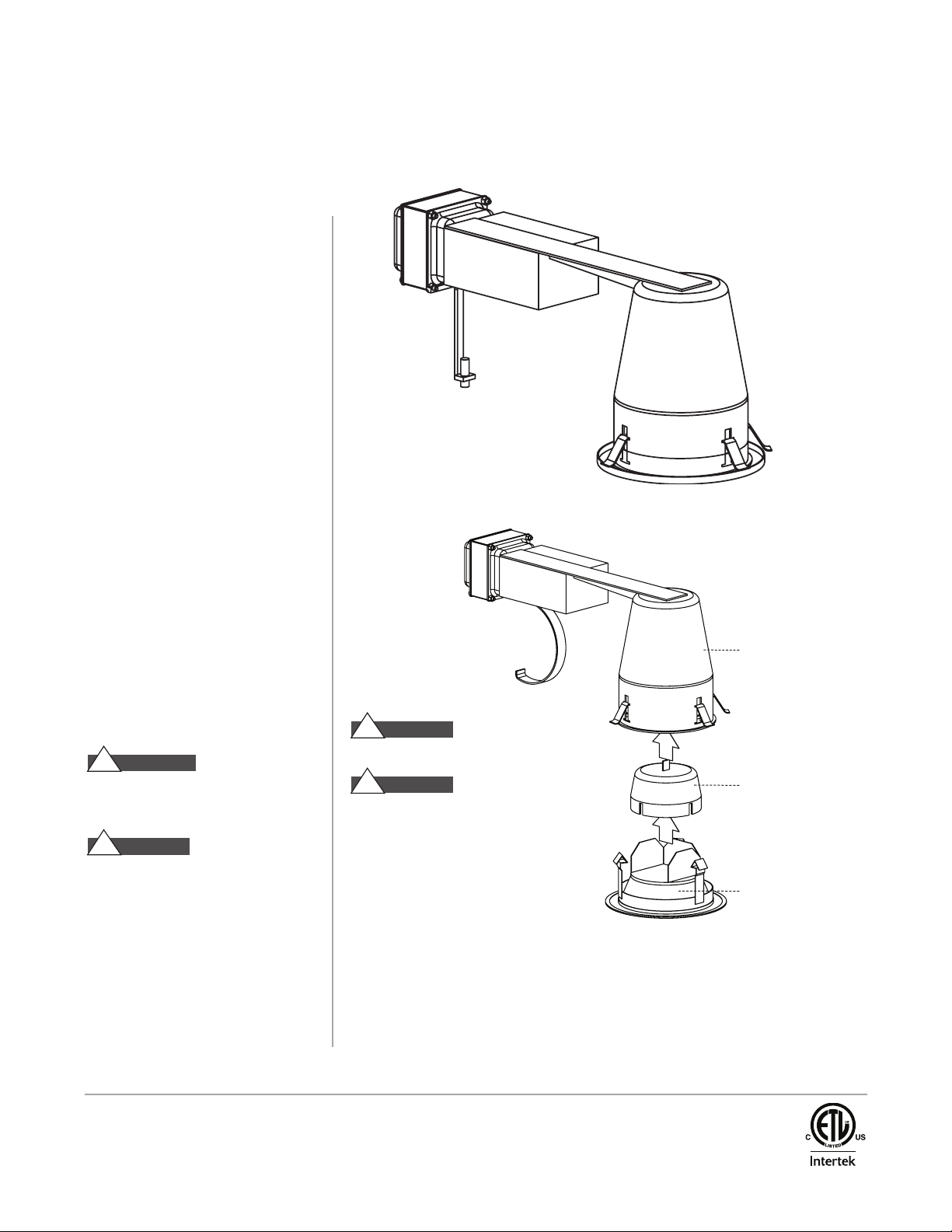
Assembled View
Exploded View
CAUTION
!
For recessed ceiling mounting only.
CAUTION
!
Suitable for operation in ambient
not exceeding 60˚C (140˚F)
IMPORTANT SAFETY INSTRUCTIONS:
1. Read all instructions
2. Do not install this LED lighting system in
damp or wet locations.
3. Luminaire is for Non-IC applications only.
No insulation on or within 3 inches of
any part of the luminaire assembly.
4. Not investigated for use in suspended ceilings.
If intended for this application then listed
clips, investigated for this use, must be
properly installed to hold the can in place.
Light Fixture
LED cluster
Fixture Lens
mr.steam
Sussman-Automatic Corporation®• www.mrsteam.com • hello@mrsteam.com
43-20 34th Street, Long Island City, NY 11101 TEL: 1 800 76 STEAM FAX: 718 472 3256
9410 S. La Cienega Blvd. Inglewood CA 90301
®
TEL: 1 800 72 STEAM FAX: 310 216 2944
PUR 100404 Rev 10/12
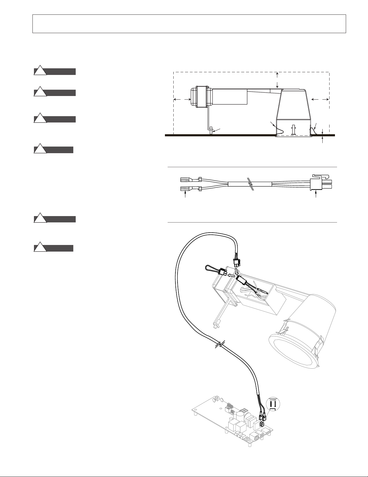
TO GENERATOR
TO LIGHT
mr.steam®chromasteam
3" MIN. CLEARANCE ALL AROUND
AND BETWEEN FIXTURE AND INSULATION
FIXTURE MUST BE INSTALLED IN A DRY LOCATION
Retainer Clip
Pulled In During
Installation
Support
Adjustment Screw
3
"
3
"
3"
Retainer clips
locked in place
to secure fixture
1
⁄2"– 11⁄8"
Ceiling Thickness
STEA M ROOM
™
Installation and Operating Instructions
INSTALLATION with iTEMPO/PLUS®and eTEMPO/PLUS®CONTROL
IMPORTANT NOTE:
WARNING
!
qualified and licensed electrician.
WARNING
!
the field wiring during installation. Turn off power at
breaker panel.
WARNING
!
away from all sides of the fixture assembly.
1. Determine the placement of the light.
CAUTION
!
(light) where direct contact with steam or water emission could occur. Do not install the light in a location
where it could become submerged.
2. The light requires a 4
3. Provide electrical service (120 VAC) with flexible
cable only. Pass cable through ceiling opening and
wire fixture in accordance with NEC and local electrical code.
WARNING
!
the steam room. The switch must be installed in a
location and manner described in the NEC and local
electric codes.
CAUTION
!
control the ChromaSteam Lights
4.
Route the 30 foot cable supplied with the ChromaSteam
from your steam bath generator through one of the
knockouts in the ChromaSteam light wiring box.
Provide a suitable strain relief bushing.
Only one MS CHROMA light may be connected to the control board in the steam generator.
Installation to be performed by a
Insure that power is not supplied to
Insulation must be a minimum of 3”
Do not install the fixture assembly
1
⁄4" diameter hole for mounting.
Figure 1
Figure 2
DO NOT install the wall switch in
Do not use a dimmer switch to
Figure 3
IMPORTANT NOTE:
be on the generator side, the Molex connector should be
routed to the light, see figure 2.
5.
Connect the quick connect tabs to the control board in
the generator at the location marked CHROMA, see
figure 4.
6.
Remove the red jumper wire shown in figure 3 and
discard. Connect the wire from the steam generator to
the connector where the jumper was.
7.
Connect the supply wires per the wiring diagram shown
on page 4. Use suitable wire nuts (not included) to
insulate and secure the supply connections.
8.
Connect copper ground wire from wiring box to ground
wire from electrical service using a wire nut to secure
the connection.
9.
Use the support adjustment screw shown to provide support for the housing on the inside surface of the ceiling
when installed.
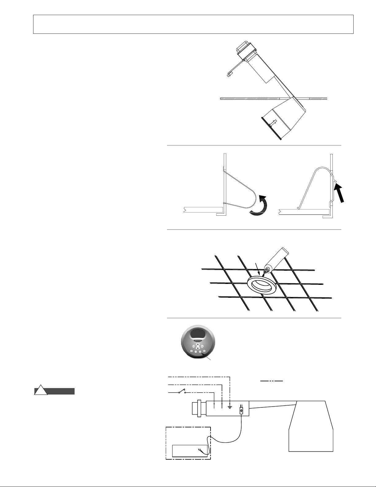
10.
With the clips folded into the fixture as shown in
figure 1 insert the wired housing into the ceiling
junction box first as shown in figure 2.
The quick connect tabs should
Figure 4
2
mr.steam®chromasteam
120 VAC
G
N
L
Field Supplied Wiring
BLACK WHITE GROUND
BLUE BLUE
WIRING BOX
WALL SWITCH
(Field Supplied)
Steambath Generator
Steambath Control Board
CHROMA
CHROMA
Apply Silicone
around the lens
where it meets
the Ceiling
SI
L
I
C
O
N
E
11.
Hold fixture up against the ceiling and push clips
through housing slot. To lock clip in place push flat
portion against the side of the fixture using a flat
head screwdriver (fig. 6).
12.
Install the LED cluster into the wedge base in the
fixture.
13.
Install the fixture lens flush with the ceiling. (fig. 7)
14.
Apply a fillet of silicone around the edge of the
fixture lens where it meets the ceiling to ensure it is
sealed from moisture.
™
Figure 5
Installation and Operating Instructions
IMPORTANT
vibration can occur, we suggest using a
NOTE: In areas where excessive ceiling
1
⁄
4
- 14 x
1
⁄
"
2
pan head sheet metal screw to lock the spring clip
against the housing. Drive the screw through the hole
provided in the spring clip and into the housing slot.
OPERATION
1. Ensure the wall switch is left in the ON position.
2. The nine color modes in order are:
a. Bright White f. Green
b. Blue/Green g. Red
c. Violet h. Chameleon
d. Blue i. Party Mode
e. Yellow
3. To cycle through the color choices turn the light off
for 1 to 2 seconds using the CHROMA button on your
eTEMPO/PLUS control as shown. When the light is
turned back on the next color will illuminate.
Continue turning the light on and off till you select
the desired light to fit your mood.
NOTE: The ChromaSteam lights can be turned ON/OFF
from the eTEMPO/PLUS control even if the steam
generator is not ON.
4. If multiple lights are installed with one wall switch
they can be synchronized. Remove all the LED
clusters except one. Turn the switch ON and
note the color. Remove that cluster and install the
next. Turn the switch ON/OFF until the second
cluster matches the first. Remove the second
cluster and repeat the process for all the clusters
used. Reinstall all the clusters when completed and
they will be synchronized.
(slow automatic cycle)
(fast automatic cycle)
Figure 6
Figure 7
Chroma button
breaker before installing LED cluster. Hot Swapping LED
clusters could render them inoperable.
Please contact Mr.Steam Technical Support
at 1-800-STEAM for replacement LED clusters,
part number 104119.
CAUTION
!
Ensure power is turned off at the
Wiring Diagram
3
 Loading...