

Page 1

Installation, Operation, and Maintenance Manual
O
®
UC
UCTIONS
EFER T
®
AudioSteam
AND
ANUAL PROVIDED WITH PROD
FOR
MPLETE INSTR
AINTENANCE
T
Feel Good Inc.
®
®
mr.steam
Page 2
IMPORTANT SAFETY INFORMATION
ing the A
N
surrounding
pe atu e a ou d t e appa at
READ ME FIRST:
1. Read and follow all instructions within this technical manual.
2. Heed all warnings, cautions, notices, and important notes.
3. Save this technical manual and leave with the homeowner.
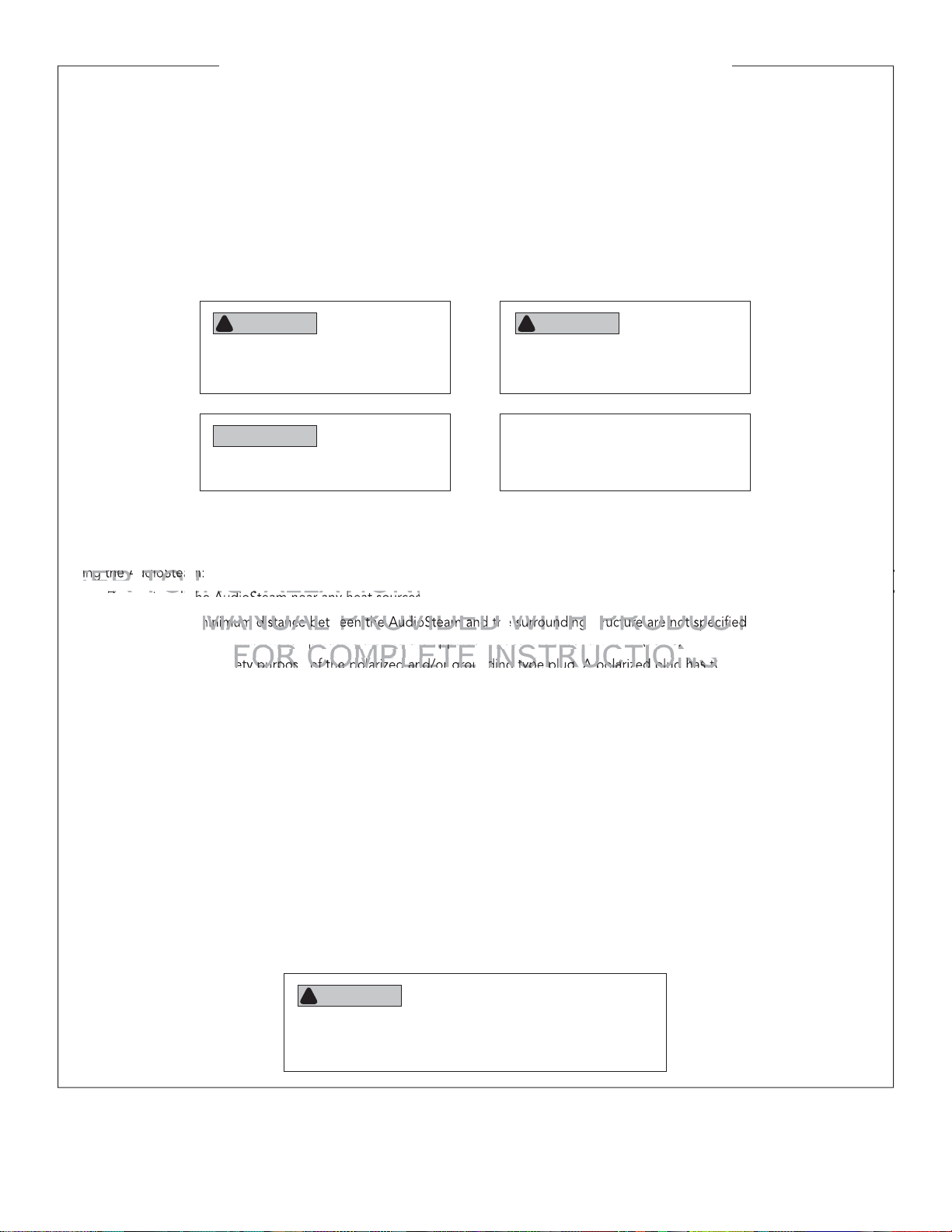
ABOUT WARNINGS, CAUTIONS, NOTICES, AND IMPORTANT NOTES:
As you follow the instructions in this technical manual, you will see four types of callouts: WARNINGS, CAUTIONS, NOTICES, and
IMPORTANT NOTES. This blocked information is important for the safe and efficient installation, maintenance, and operation of
the AudioSteam. These callouts are described as follows:
WARNING
!
Indicates a potentially hazardous situation,
which, if not avoided, may result in death
or serious injury.
NOTICE
Indicates a situation, which, if not avoided,
may result in property damage.
CAUTION
!
Indicates a potentially hazardous situation,
which, if not avoided, may result in minor
or moderate injury.
IMPORTANT NOTE
Indicates information that is especially
relevant to a problem-free installation.
SAFETY INSTRUCTIONS:
To prevent personal injury and or product damage, please read the following important safety instructions carefully before installing the AudioSteam:
• Do not install the AudioSteam near any heat sources.
• Clearance and minimum distance between the AudioSteam and the surrounding structure are not specified as long as they are
sufficient so that the ambient temperature around the apparatus does not exceed 140 °F (60 °C).
• Do not defeat the safety purpose of the polarized and/or grounding type plug. A polarized plug has two blades, with one
wider than the other. A grounding type plug has two blades and a third grounding prong. The wide blade or the third prong
are provided for your safety. If the provided plug does not fit into your outlet, consult an electrician for replacement of the
obsolete outlet.
• Protect the power cord from being walked on or pinched, particularly at plugs, convenience receptacles, and at the point
where the cord exits from the apparatus.
• Only use attachments/accessories specified by the manufacturer.
• All servicing to be performed by qualified service personnel. Servicing is required when the AudioSteam is damaged in any
way, including when the power-supply cord or plug is damaged, liquid is spilled into or objects fall into the AudioSteam,
AudioSteam is exposed to rain or moisture, the AudioSteam does not operate normally, or the AudioSteam dropped.
• Do not disassemble or alter the AudioSteam in any way.
• Clean the AudioSteam with a dry cloth only. Beware of the application of some products commonly used against corrosion
(such as WD-40
rials of the AudioSteam. Any other materials that may come in contact with the AudioSteam must be carefully evaluated under
end-use conditions for compatibility.
®
family products), as some industrial oils can have negative chemical reactions and damage the housing mate-
PERATION AND
AINTENA
NOTE: All information in this technical manual is based on the latest product information available at the time of
publication. Sussman-Automatic Corporation reserves the right to make changes at any time without notice.
WARNING
!
These instructions are for use by qualified service personnel
only. To reduce the risk of electric shock, do not perform
any servicing, other than that contained in these instructions.
2
Page 3
IMPORTANT SAFETY INFORMATION (cont.)
.
electrocution. Do no
d
s, additional audio/vid
connect any auxiliary comp
connect any auxiliary com
(for exa
.
ystem
cable, additional spe
o
are not pr
n
WARNING
!
Before installing or connecting the AudioSteam, please read the following:
• To prevent a shock hazard, do not disassemble or alter the AudioSteam.
• To prevent overtemperature shutoff and equipment damage, do not use foam to insulate the AudioSteam.
• To prevent a shock hazard, turn power off before servicing or changing any cable connections in the
AudioSteam.
• To prevent electric shock hazard and/or water damage to the AudioSteam, all conduits must be plugged with
the included foam blocks.
• To prevent a shock hazard do not install the AudioSteam in a location where it can get wet. Audiosteam must
be installed in a dry, indoor location.
• AudioSteam must be disposed of separately in accordance with local waste disposal legislation.
WARNING
!
• Risk of electric shock. Do not leave compartment door open.
isk electric shock. Replace components
• Risk of electric shock. Replace components only with identical components.
• Prevent electrocution. Do not connect any auxiliary components (for example cable, additional speakers, head-
• These units are not provided or intended to be connected to an outdoor antennae; to prevent electrocution
• Opening or removing covers may expose you to dangerous voltage or other risk of injury. All servicing to be
• When the power supply connections or power supply cord(s) are damaged; if water is entering the audio/video
• This unit should be subjected to periodic routine maintenance (for example, once every 3 months) to make sure
• Product must be disposed of separately in accordance with local waste disposal legislation.
s, additional audio/vi
phones, additional audio/video components, etc.) to the system.
are not pr
only use the supplied antennae and install it in accordance with these instructions.
performed by qualified service personnel.
compartment or any electrical equipment compartment area; if the protective shields or barriers are showing
signs of deterioration; or if there are signs of other potential damage to the unit, turn off the unit and refer servicing to a qualified service personnel.
that the unit is operating properly.
o components, etc.) to the
ed or intended to be conned to an outdoor antennae; to preve
nly with identical components
stem
AND
3
Page 4

mr.steam
O
page lef
blank intentio
AND
UC
UCTIONS
®
INSTALLATION, OPERATION, AND MAINTENANCE AudioSteam
®
EFER T
This page left blank intentionally
ANUAL PROVIDED WITH PROD
FOR
MPLETE INSTR
AINTENANCE
T
4
Page 5
mr.steam
O
the
p
FM antenna and auxiliary co
FM antenna and auxiliary co
AND
ge
the steam g
r
Bluetooth-ena
devicebled device
EFER T
®
INSTALLATION, OPERATION, AND MAINTENANCE AudioSteam
INSTALLER INSTRUCTIONS
1. General information ....................................................................................6
Box contents ....................................................................................................... 6
AudioSteam general installation ........................................................................ 6
2. Installing AudioSteam ................................................................................. 8
AudioSteam dimensions ..................................................................................... 8
Locating and installing AudioSteam ................................................................... 8
3. Connecting AudioSteam .............................................................................. 9
Connecting AudioSteam ....................................................................................9
Removing the AudioSteam cover.......................................................................9
Connecting the FM antenna and auxiliary cord ............................................... 10
Connecting speakers and subwoofer ............................................................... 10
ANUAL
FOR
Connecting AudioSteam to the steam generator ............................................ 11
Pairing a Bluetooth-enabled device ................................................................. 12
4. AudioSteam specifications ........................................................................13
5. Regulatory statements ..............................................................................15
TABLE OF CONTENTS
onnecting s
onnecting AudioSteam tothe steam
a
®
erato
HOMEOWNER/END-USER INSTRUCTIONS
6. About AudioSteam ....................................................................................16
7. Operating AudioSteam ............................................................................. 17
8. AudioSteam warranty ............................................................................... 18
®
mr.steam
Sussman-Automatic Corporation® • www.mrsteam.com • [email protected]
43-20 34th Street, Long Island City NY 11101 1 800 76 STEAM FAX: 718 472 3256
9410 S. La Cienega Blvd., Inglewood CA 90301 1 800 72 STEAM
FAX: 310 216 2944
5
PUR 100516 REV 6.17
Page 6

mr.steam
O
AND
AudioSteamAudioSteam
ante
cableControl cable
UCTIONS
®
INSTALLATION, OPERATION, AND MAINTENANCE AudioSteam
INSTALLER INSTRUCTIONS
1. General information
Box contents
®
T
FM antenna
AudioSteam
FOR
MPLETE INSTR
AudioSteam general installation
Figure 1 shows how the AudioSteam interconnects with the
steam generator, iSteam3, and audio speakers.
Figure 2 shows how to use the AudioSteam as a standalone
system within your steam room (i.e., if your steam room does
not use iSteam3).
Control cable
IMPORTANT NOTE
AudioSteam only integrates with
iSteam3.
All drawings are for illustrative purposes only.
6
Page 7

mr.steam
O
UC
T
T
)Speaker wire (100 ft max)
p()
®
INSTALLATION, OPERATION, AND MAINTENANCE AudioSteam
Speaker wire (100 ft max)
®
EFER T
Antenna (4 ft)
AudioSteam
Grounded wall outlet
Power cord (6 ft)
AudioSteam control cable (30/60 ft)
In-room control cable (30/60 ft)
Steam
generator
(dry)
INSTALLATION,
Figure 1
gure 1
STEAM ROOM
ANUAL PROVIDED WITH PROD
Speakers
iSteam3
(wet)
AND
INSTALLER
AINTENANCE
T
AudioSteam
Grounded wall outlet
Power cord (6 ft)
In-room control cable (30/60 ft)
Steam
generator
Antenna (4 ft)
(dry)
Figure 2
eaker wire (100 ft max
Speaker wire (100 ft max)
Speakers
iTempo,
iTempoPlus,
AirTempo
STEAM ROOM
(wet)
All drawings are for illustrative purposes only.
7
Page 8

mr.steam
g
g
t
ss for t
5Figure 5
)
).
pp
UC
T
T
9 mm) is required to ensure
®
INSTALLATION, OPERATION, AND MAINTENANCE AudioSteam
2. Installing AudioSteam
AudioSteam dimensions
Figure 3 shows the face-on dimensions of AudioSteam.
Figure 4 shows the side-view dimensions of AudioSteam.
INSTALLER
WARNING
!
Shock hazard. Do not place the control box in a location where it can get wet.
®
Locating and installing AudioSteam
To prevent water from getting inside the device, AudioSteam should
be mounted on two stable vertical surfaces (e.g., studs) as shown in
Figure 5.
Using screws and washers, firmly attach AudioSteam using the upper
mounting holes, one at a time, on each side of the unit. Repeat the
process for the lower mounting holes (Figure 5).
pro
ss for
NOTICE
A clearance of at least 0.75” (19 mm) is required to ensure free
heat circulation at the back of the unit.
IMPORTANT NOTES
1. The following materials (not included) are recommended to
install AudioSteam:
2. To prevent overtemperature shutoff and equipment damage,
do not use foil insulation in front of AudioSteam.
3. Place AudioSteam far from any electrical noise source, such as
variable speed controls and motors, to prevent interference
that will affect audio quality.
4. In the event of an overtemperature condition, AudioSteam
automatically reduces the volume to protect the amplifier from
damage.
5. To prevent overtemperature shutoff, do not locate in an attic
or other location where ambient temperature may reach 140 °F
(60 °C).
lower mounting holes (
gure
.
PROVIDED
ast 0.75”
• Four #10 screws of appropriate length with round, truss,
or pan head.
• Four washers with 0.5” outer diameter x 0.0625” thickness (12 mm outer diameter x 1.5 mm thickness).
9 mm) is required to ensure
e
Figure 3
AND
PROD
Figure 4
Figure 5
All drawings are for illustrative purposes only.
8
Page 9

mr.steam
g a Phis-head
ON
A
AAAAA
O
T
T
AudioS
shown in
U
®
INSTALLATION, OPERATION, AND MAINTENANCE AudioSteam
3. Connecting AudioSteam
®
Connecting AudioSteam
To connect AudioSteam to the steam generator, perform
one or more of the following connections:
• Connect the FM antenna (included) and auxiliary cord
to AudioSteam.
• Connect speakers and subwoofer to AudioSteam
with speaker wire.
• Connect AudioSteam to the steam generator’s motherboard or daughterboard with the AudioSteam control cord.
• Pair a Bluetooth-enabled device to AudioSteam.
Removing the AudioSteam cover
To remove the AudioSteam cover:
1.
Using a Phillips-head screwdriver, remove the two
sig a Phi
cover screws from the front of the AudioSteam
(Figure 6), and remove the cover from the unit.
2.
Connect the outputs of AudioSteam as shown in
Figure 7.
3.
Remove the two foam block inserts from the inner wir-
ing channels and set aside (Figure 8).
screwdriver, remove the two
remove the cover fro the unit.
of
as
PERATI
WARNING
!
• To reduce the risk of electric shock, do not
remove the screws on the back of AudioSteam.
No user-serviceable parts inside. Refer servicing
to qualified service personnel.
• To prevent electric shock, do not connect
AudioSteam to main power supply while the
cover is removed.
• AudioSteam does not come with speakers
and speaker wiring. The connection between
AudioSteam and the speakers must be “Class 2
Wiring” and installed by qualified personnel.
A
WITH PR
NANCE
INSTR
INSTALLER
Auxiliary and
FM outputs
Power
cord
Speaker and
subwoofer
outputs
All drawings are for illustrative purposes only.
Figure 6
Controller
cord
Foam block
inserts
Figure 8Figure 7
9
Page 10

mr.steam
AAAAA
AAAA
A
c
wires, the rec
TTT
T
socket cr
n
contact is an
S
T
®
INSTALLATION, OPERATION, AND MAINTENANCE AudioSteam
®
Connecting the FM antenna
and auxiliary cord
1. Plug the included FM antenna into the antenna
output and route the wire through the strain relief
channel as illustrated (Figure 9). For best reception, fully deploy the antenna in a vertical orientation outside of the AudioSteam housing.
INSTALLER
2.
Connect a 1/8” (3.5 mm) stereo audio cord (not
included) to the auxiliary output, and route the
cable through the strain relief channel as illustrated (Figure 9). Connect the free end of the audio
cord to a mobile device or digital music player.
Connecting speakers and
subwoofer
1. Connect individual speaker wires — or a 10-pin
MATE-N-LOK adapter with attached wires — to
the speaker outputs. Refer to Figure 10 and
Figure 11 for connector identification.
EFER
IMPORTANT NOTES
• If you use individual speaker wires, the rec-
• If you use a 10-pin MATE-N-LOK adapter
2. Route the wires through the molded relief channel. Connect the speaker wires to suitable speakers and subwoofer.
3.
Replace the foam block inserts (Figure 9).
4.
Secure the cover using the two cover screws.
use individual speakewires, the re
ommended socket crimping contact is an
AWG 14-20 (TE Connectivity part number
350550-3).
with attached wires, the required housing
connector is a 10-position Universal MATEN-LOK (TE Connectivity part number
926302-3).
(TE Con
ctivity part number
Replace
foam
blocks
Auxiliary
cord
FM
antenna
Figure 9
Route
wires
NANCE
IN
Figure 10
CONNECTOR IDENTIFICATION
1 Front Left speaker (+)
2 Front Left speaker (-)
3 Front Right speaker (-)
4 Front Right speaker (+)
5 Rear Left speaker (+)
6 Rear Left speaker (-)
7 Rear Right speaker (-)
8 Rear Right speaker (+)
9 Subwoofer (+)
10 Subwoofer (-)
Figure 11
All drawings are for illustrative purposes only.
10
Page 11

mr.steam
t.t
A
ODU
T
UCTIO
®
INSTALLATION, OPERATION, AND MAINTENANCE AudioSteam
Connecting AudioSteam
to the steam generator
To operate the AudioSteam via iSteam3, you must connect the
AudioSteam (Figure 12) to an internal connector in the steam generator.
WARNING
!
Shock hazard. Shock hazard. Power must be disconnected at the
main electrical supply before removing the steam generator cover.
For information about the steam generator, refer to the installation, operation, and maintenance manual supplied with the steam
generator (also found at www.mrsteam.com/technical).
Remove the steam generator cover, and remove knockout on
1.
steam generator.
2.
Connect the control cable directly to the steam generator’s circuit
board (A in Figure 13), OR if an additional accessory is installed
in the steam generator, connect the control cable to the supplied
daughterboard (B in Figure 13).
Power cord to
120V grounded
outlet
®
INSTALLER
Control
cable
Figure 12
3.
Plug the AudioSteam power cord into a 120V grounded electrical
outlet.
Control
cable
Steam generator
circuit board
Steam generator
circuit board
A
R
PROVIDED WITH
MPLETE INST
Steam generator
(shown with cover
Control
cable
Daughterboard
removed)
B
N
Steam generator
circuit board
Control cable
Knockout
All drawings are for illustrative purposes only.
Figure 13
11
Page 12

mr.steam
AudioS
AudioS
am.am
AND
l b
ic
l be given to the dev
U
he
that was first detected in the
O
UCTIONS
®
INSTALLATION, OPERATION, AND MAINTENANCE AudioSteam
Pairing a Bluetooth-enabled device
Before playing a Bluetooth-enabled device via iSteam3 (see “Operating AudioSteam” on
Page 17), you must pair your device to AudioSteam.
To pair a Bluetooth-enabled device to AudioSteam:
1. Ensure that the mobile device is in range of AudioSteam, and that it is powered on
and Bluetooth is turned on.
INSTALLER
2.
Open the Bluetooth settings on your device.
3. Select AudioSteam in the list of discoverable Bluetooth devices.
4.
When prompted, enter the following passcode: 5555.
5.
Once the pairing is complete, select AudioSteam on your mobile device to connect
to AudioSteam.
IMPORTANT NOTES
• If the device moves out of range and loses connection, it should reconnect automatically with AudioSteam (without having to go through the pairing process again) when
moved within range.
• AudioSteam will store up to eight devices in its memory. If one of the last three paired
devices is in range and has Bluetooth turned on, it will automatically connect to
AudioSteam.
• If multiple devices are within range and have already been paired with AudioSteam,
priority will be given to the device that was first detected in the AudioSteam memory.
e given to the dev
that was first detected in t
udioSteam mory.
®
AINTENANCE
FOR
MPLETE INSTR
All drawings are for illustrative purposes only.
12
Page 13

mr.steam
subwoofe
AND
plifier type:plifier type:
DClass D
ppp
p
®
INSTALLATION, OPERATION, AND MAINTENANCE AudioSteam
4. AudioSteam specifications
ENVIRONMENTAL RATINGS
Operating temperature: -4 °F (-20 °C) to 140 °F (60 °C)
®
EFER
Storage temperature: -22 °F (-30 °C) to 185 °F (85 °C)
Humidity: 70% max
Water resistance: IPX5
MECHANICAL
Weight: 3.6 lb (1.64 Kg)
Dimensions (W x H x D): 9.81” x 2.58” x 8.88” (249 mm x 65 mm x 226 mm)
LINE INPUT
Input voltage: 100-240VAC 50/60Hz
AUDIO OUTPUTS
Maximum number of speakers: 4
Maximum number of subwoofer: 1
Maximu number of
Audio amplifier type: Class D
Output power (speaker output): 25 W
Output power (subwoofer): 50 WRMS , 100 W peak
Output impedance (speaker): 4-8 Ohms
Output impedance (subwoofer): 2-4 Ohms
r:
RMS , 50 W peak
INSTALLER
Harmonic distortion (speaker): 0.015% at 1 W (1 KHz)
Harmonic distortion (subwoofer): 0.015% at 1 W (100 Hz)
Frequency response (speaker): 5 Hz to 20 KHz F
Frequency response (subwoofer): 10 Hz to 200 Hz
AUXILIARY INPUTS
Maximum number of inputs: 1
Connection type: 1/8” (3.5 mm) stereo jack
Maximum voltage: 2.2 Vpp
Impedance: 100 Kohms
13
(continued on next page)
Page 14

mr.steam
O
A
:Antenna type
AND
supported:Profiles supported:
A2DP, A
A2DP, A
®
INSTALLATION, OPERATION, AND MAINTENANCE AudioSteam
AudioSteam specifications (cont.)
FM RECEIVER
Frequency band: 87.5 MHz to 107.9 MHz
®
INSTALLER
RF sensitivity: 2.2 μV
Harmonic distortion: 0.1% à 1 KHz
Frequency response: 30Hz à 15 KHz
FM decoder: Stereo Multiplex
Antenna type: 1 m (39”) cable
Antenna connector: 1/8” (3.5 mm) stereo jack
BLUETOOTH RECEIVER
Frequency band: 2400 MHz to 2483.5 MHz
Transmit power: Class 2, 4 dBm
Bluetooth version: Bluetooth v4.1
Antenna type: Modular integrated
EFER T
ntenna type
Profiles supported: A2DP, AVRCP
USB PLAYER
Compatibility: USB 1.1, 2.0 and 3.0
File format support: MP3 (files on the root)
Disk size: 8GB to 32GB
Modular integrated
Disk format: FAT32
Cluster size: 4 Ko to 32 Ko
Connector type: USB type A
APPLICABLE STANDARDS
UL 60065
CAN/CSA-C22.2 No. 60065-03
EN 60065
AS/NZS 60065
AudioSteam is compliant with the Radio Equipment Directive (RED)
14
Page 15

mr.steam
c
the equipment into an outlet on a ci
t different from that to which t
AND
void th
user s authority to operate t
s equipment.s equipment.
®
INSTALLATION, OPERATION, AND MAINTENANCE AudioSteam
5. Regulatory statements
FCC Compliance Statement
®
Contains Transmitter Module FCC ID: A8TBM23SPKXYC2A
This device complies with Part 15 of the FCC Rules. Operation is subject to the following two conditions:
(1) this device may not cause harmful interference, and (2) this device must accept any interference received, including
interference that may cause undesired operation.
Note:
This equipment has been tested and found to comply with the limits for a Class B digital device, pursuant to part 15 of
the FCC Rules. These limits are designed to provide reasonable protection against harmful interference in a residential
installation. This equipment generates, uses and can radiate radio frequency energy, and if not installed and used
in accordance with the instructions, may cause harmful interference to radio communications. However, there is no
guarantee that interference will not occur in a particular installation. If this equipment does cause harmful interference
to radio or television reception, which can be determined by turning the equipment off and on, the user is encouraged
to try to correct the interference by one or more of the following measures:
• Reorient or relocate the receiving antenna.
• Increase the separation between the equipment and receiver.
• Connect the equipment into an outlet on a circuit different from that to which the receiver is connected.
Connecthe equipment into an outlet on a cir
• Consult the dealer or an experienced radio/TV technician for help.
Caution: To assure continued compliance, any changes or modifications not expressly approved by the party responsible for compliance could void the user’s authority to operate this equipment.
FCC RF Exposure Statement
The device has been evaluated to meet general RF exposure requirement. The device can be used in portable exposure condition without restriction.
t different from that to which t
receiver isonnected.
INSTALLER
IC Compliance Statement
Contains transmitter module IC: 12246A-BM23SPKXYC2
This device complies with Industry Canada licence-exempt RSS standard(s). Operation is subject to the following two
conditions: (1) this device may not cause interference, and (2) this device must accept any interference, including interference that may cause undesired operation of the device.
Caution: To assure continued compliance, any changes or modifications not expressly approved by the party responsible for compliance could void the user’s authority to operate this equipment.
RSS-102 RF Exposure Statement
This equipment complies with Industry Canada radiation exposure limits set forth for an uncontrolled environment.
15
Page 16

mr.steam
SNT NOTES
UC
having
ge.thin range.
through the pairing proc
again)
®
INSTALLATION, OPERATION, AND MAINTENANCE AudioSteam
®
HOMEOWNER/END-USER INSTRUCTIONS
6. About AudioSteam
AudioSteam offers you the perfect means to bring music into your steam
room. AudioSteam is compatible with numerous audio sources:
• Connect to a mobile device or digital music player using the auxiliary audio input.
• Connect to a mobile device via Bluetooth.
• Tune in to an FM station using the AudioSteam’s integrated FM
receiver.
AudioSteam can connect to four speakers and one subwoofer.
AudioSteam lets you control music from the iSteam3 interface, or may be
used as a standalone device.
IMPORTANT NOTES
• If a Bluetooth-connected device moves out of range and loses connection with AudioSteam, it should reconnect automatically with
AudioSteam (without having to go through the pairing process again)
when moved within range.
• AudioSteam will store up to eight devices in its memory. If one of the
last three paired devices is in range and has Bluetooth turned on, it
will automatically connect to AudioSteam.
• If multiple devices are within range and have already been paired with
AudioSteam, priority will be given to the device that was first detected
in the AudioSteam memory.
T NOTE
oth-connected device
in ran
ves out of range and loses
go
AND
PROD
AINTENANCE
T
16
Page 17

mr.steam
the
p the
left or right to control vo
eft or right to control
TETE
.)
(ume (
AA
.
(button (
r
) to play or
)
)
k.
p
y
y
(am (
tap the), tap the
icon (con (
AA
then tap thed then tap the
®
INSTALLATION, OPERATION, AND MAINTENANCE AudioSteam
7. Operating AudioSteam
®
Using iSteam3, you can control your AudioSteam-connected mobile device or music player
from within your steam room. Control your digital music player (e.g., Apple iPod), mobile
device, or FM stations, all from the simple AudioSteam interface.
To operate AudioSteam using iSteam3:
Boot iSteam3 and wait for the iSteam3 home screen to appear.
1.
2. To turn on AudioSteam (Figure 14), tap the
button (B).
3.
Tap the
4.
A list of available playback devices will appear (Figure 16). Tap the desired device
(A), and then tap the
DISCONNECT button (C).
5.
To control FM radio (Figure 17):
a. Slide the
b. Tap the MUTE button to mute all sound (B).
c. Tap the FORWARD and BACK buttons (C and D) to scan FM stations.
6.
To control an auxiliary-connected or Bluetooth-connected device (Figure 18):
a. Slide the
b. Tap the MUTE button to mute all sound (B).
c. Tap the FORWARD and BACK buttons (C and E) to select a track in the device’s playlist.
d. Tap the
7.
To turn off AudioSteam (Figure 19), tap the
button (B).
SETTINGS icon (A in Figure 15).
PLAY icon (B). To disconnect an active Bluetooth device, tap the
VOLUME CONTROL left or right to control volume (A).
VOLUME CONTROL left or right to control volume (A).
.
the
utton to mute all sound (
PLAY button (D) to play or pause the track.
utton
) to play o
,
MUSIC icon (A), and then tap the MUSIC
)
ause the trac
POWER icon (A), and then tap the MUSIC
, a
AND
AudioSteam only interfaces
with iSteam3.
IMPORTANT NOTES
• For complete instruc-
• To control a Bluetooth-
NOTICE
tions on operating the
iSteam3, refer to the
iSteam technical manual
(see www.MrSteam.com).
enabled device from
iSteam3, you must
first pair the device to
the AudioSteam. See
“Pairing a Bluetoothenabled device” on
page 12 for instructions.
HOMEOWNER/END-USER
All drawings are for illustrative purposes only.
Figure 14
Figure 17
Figure 15
Figure 18
17
Figure 16
Figure 19
Page 18

mr.steam
O
UC
UCTIONS
®
INSTALLATION, OPERATION, AND MAINTENANCE AudioSteam
8. AudioSteam warranty
To view or download the Mr. Steam® Accessory
Warranty and register your product, go to:
blog.mrsteam.com/wr or scan this QR code:
®
T
INSTALLATION,
PERATION AND
AINTENANCE
ANUAL PROVIDED WITH PROD
HOMEOWNER/END-USER
FOR
MPLETE INSTR
T
18
Page 19

mr.steam
AND
MM
UCTIONS
Notes:
®
INSTALLATION, OPERATION, AND MAINTENANCE AudioSteam
®
FOR
MPLETE INSTR
HOMEOWNER/END-USER
19
Page 20

mr.steam
O
UC
UCTIONS
®
T
AND
®
Feel Good Inc.
ANUAL
FOR
Call Sales & Support at 1 800 76 STEAM (East Coast) or 1 800 72 STEAM (West Coast) for more information.
mr.steam
43-20 34th Street, Long Island City NY 11101 9410 S. La Cienega Blvd., Inglewood CA 90301
TEL
: 1 800 76 STEAM
®
Sussman-Automatic Corporation
FAX
: 718 472 3256
MPLETE INSTR
www.mrsteam.com
Products, information and specifications are subject to change without notice.
®
TEL
: 1 800 72 STEAM
FAX
: 310 216 2944
PROD
AINTENANCE
T
Copyright © 2017 Sussman-Automatic Corporation I MrSteam and des., A Lifetime of Pleasure, AirTempo, AromaFlo, AudioSteam, AudioWizard, AutoFlush, AutoSteam, Butler Package, ChromaSteam,
Clean Steam...Every Time, Club Therapy, Digital 1, Express Steam, Feel Good Inc., From Bathroom to Spa, HomeWizard, iButler, iGenie, iSizing, iSteam, iTempo, iTempo/Plus, Making Wellness a Way of Life,
MusicTherapy, SmartSizing, Spa Package, Steam Genie, Steam on Demand, Steam@Home, SteamStart, StemStop, SteamTherapy, Sussman, Tala, The Intelligent Steambath, Valet Package, Virtual Spa System,
Voice Genie, and Voice Wizard are registered trademarks of Sussman-Automatic Corporation. PUR 100516 REV 6.17
 Loading...