

Mr. Steam MSBUTLER1RDWH, BUTLERL1RBK, MSBUTLER1SQORB, MSBUTLER1RDBB, BUTLERL1SSB Specifications
...Page 1
mr.steam
®
Technical Specifications
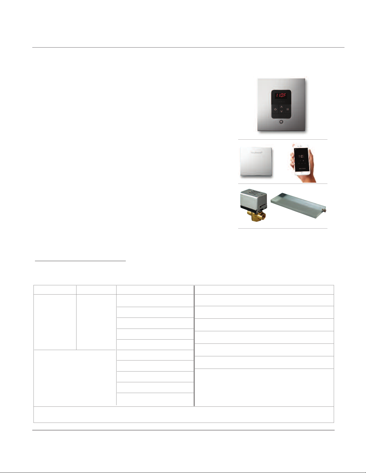
Butler Package
®
BUTLER PACKAGE 1
For models MS 90E to MS SUPER 3E
BOX CONTENT
• iTempoPlus®Control • AromaSteam Steamhead
• AutoFlush
• Condensation Pan
®
• SteamLinx
BUTLER PACKAGE 2
For models MS SUPER 4E to MS SUPER 6E
BOX CONTENT
Same as Butler Package with an additional Steamhead,
AutoFlush, and Condensation Pan.
NOTE: When ordered with the Linear Steamhead, standardSteamhead(s) are replaced with 104216 Linear Steamhead(s)
™
FOR ILLUSTRATIVE PURPOSES ONLY. IMPORTANT NOTE: FOR SAFE AND TROUBLE FREE INSTALLATION
visit mrsteam.com before installation to download the Installation, Operation and Maintenance Manual or refer to
the manual provided with the unit.
MODEL SHAPE FINISH PROJECT INFORMATION
MS BUTLER 1
MS BUTLER 2
OPTIONS:
Linear Steamhead
Notes:
RD Round
SQ Square
PC - Polished Chrome
BN - Brushed Nickel
PN - Polished Nickel
ORB - Oil Rubbed Bronze
BB - Brushed Bronze
PB - Polished Brass
SB -
Satin Brass
BK - Black Fascia
WH - White Fascia
RAW -
Custom Plating
Location:
Architect:
Engineer:
Contractor:
Submitted By:
Date:
mr.steam
43-20 34th Street, Long Island City, NY 11101 TEL : 1 800 76 STEAM FA X: 718 472 3256
9410 S. La Cienega Blvd. Inglewood CA 90301 T EL: 1 800 72 STEAM FAX: 310 216 2944
®
Sussman-Automatic Corp
®
[email protected] www.mrsteam.com
TS0009 7.17
Page 2

mr.steam
®
Technical Specifications
AutoFlush
®
Box Contents
• AutoFlush Valve with Cord
• Installation instructions
Operation
The optional AutoFlush System feature automatically drains the
®
Mr.Steam
A time delay allows the water to cool
down (about two hours) before it
drains by gravity for a safe and gentle
operation.
Note:
has been installed, the AutoFlush will
drain for ten minutes then refill with
fresh water to begin the pre-heat
cycle.
system following each use.
If the Express Steam®option
AutoFlush Shown Fully Assembled
Steam Generator
DO NOT TURN OR REMOVE THE DRAIN VALVE
(shown in the correct open position)
Drain Valve
AutoFlush Valve
Nipple
Plumb to
Drain Line
Our exclusive AutoFlush® automatically and electronically drains the system,
®
providing CleanSteam... Every Time
FOR ILLUSTRATIVE PURPOSES ONLY. IMPORTANT NOTE: FOR SAFE AND TROUBLE FREE INSTALLATION
visit mrsteam.com or scan the QR code before installation to download the Installation, Operation and
Maintenance Manual or refer to the manual provided with the unit.
MODEL PROJECT INFORMATION
MS 81500E
Notes:
mr.steam
mr.steam
43-20 34th Street, Long Island City, NY 11101 tel: 1 800 76 STEAM fax: 718 472 3256
43-20 34th Street, Long Island City, NY 11101 tel: 1 800 76 STEAM fax: 718 472 3256
9410 S. La Cienega Blvd. Inglewood CA 90301 tel: 1 800 72 STEAM fax: 310 216 2944
9410 S. La Cienega Blvd. Inglewood CA 90301 tel: 1 800 72 STEAM fax: 310 216 2944
Location:
Architect:
Engineer:
®
®
Sussman-Automatic Corp®
Sussman-Automatic Corp®
and introduces fresh water.
Contractor:
Submitted By:
Date:
[email protected] www.mrsteam.com
[email protected] www.mrsteam.com
TS0011 REV 5.14
Page 3
mr.steam
9”
1.5”
25”
®
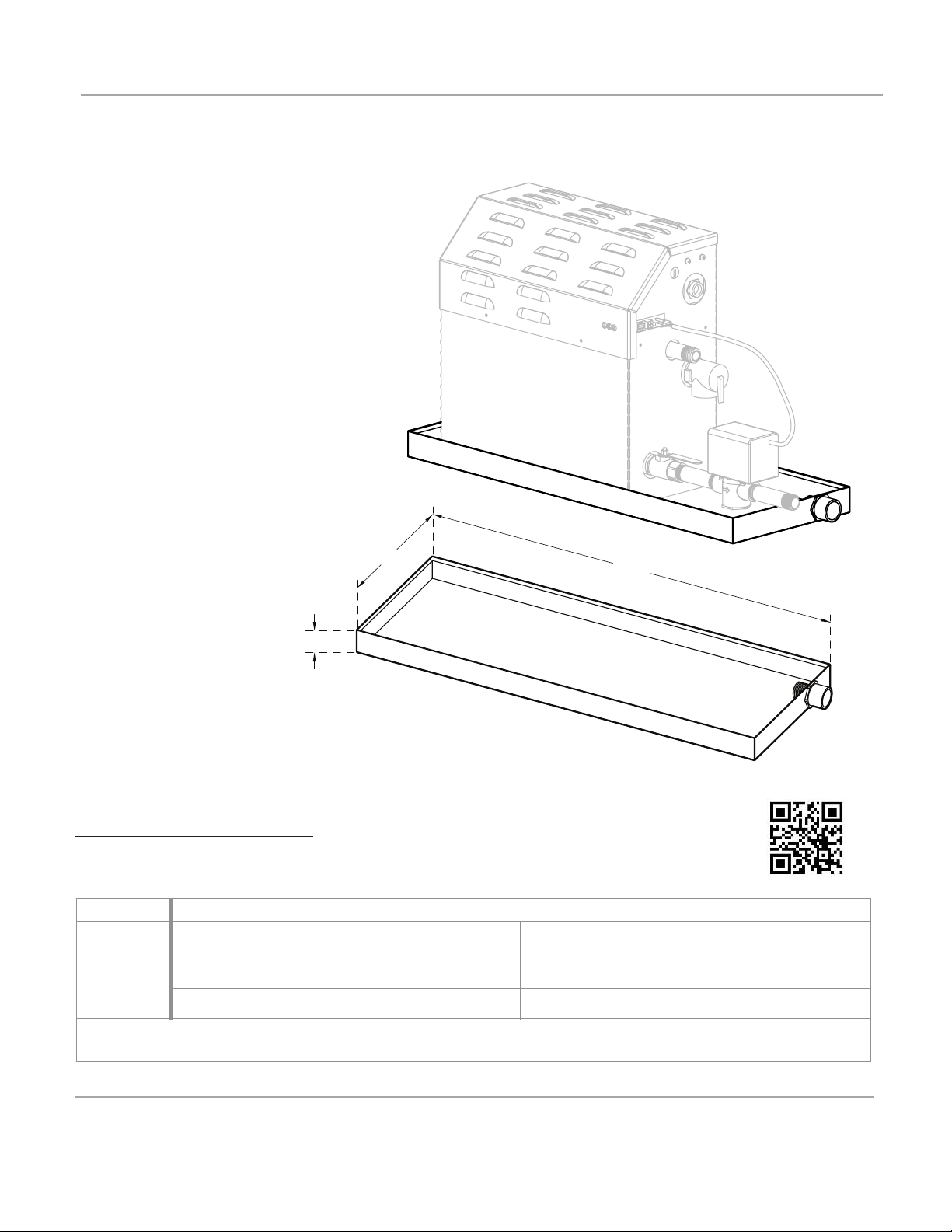
Drip Pan MS 103867
Mr. Steam strongly recommends the use of
a drain pan in the unlikely event of a
plumbing leak.
Locate the drain pan on a solid level
surface and place the steam generator
inside the drain pan. Insure the steam
generator is level.
All plumbing shall be performed by a
qualified licensed plumber and in accordance with applicable national and local
codes. Check local plumbing code for
receptor, trap and vent requirements.
Drain pans drain by gravity.
The drain pan is equipped with an integral
3
⁄4" NPT fitting.
Technical Specifications
FOR ILLUSTRATIVE PURPOSES ONLY. IMPORTANT NOTE: FOR SAFE AND TROUBLE FREE INSTALLATION
visit mrsteam.com or scan the QR code before installation to download the Installation, Operation and
Maintenance Manual or refer to the manual provided with the unit.
MODEL PROJECT INFORMATION
MS 103867
Notes:
mr.steam
43-20 34th Street, Long Island City, NY 11101 tel: 1 800 76 STEAM fax: 718 472 3256
9410 S. La Cienega Blvd. Inglewood CA 90301 tel: 1 800 72 STEAM fax: 310 216 2944
Location:
Architect:
Engineer:
®
Sussman-Automatic Corp®
Contractor:
Submitted By:
Date:
[email protected] www.mrsteam.com
TS0012 REV 5.14
Page 4
3”
2
3
/
4
”
3
”
3”
7
/8”
03”
1”
mr.steam
®
Technical Specifications
AromaSteam Steamhead
• Even distribution of steam while
remaining cool to the touch
• No field assembly required
• No moving parts
• Integrated aromatherapy oil
well for in shower use
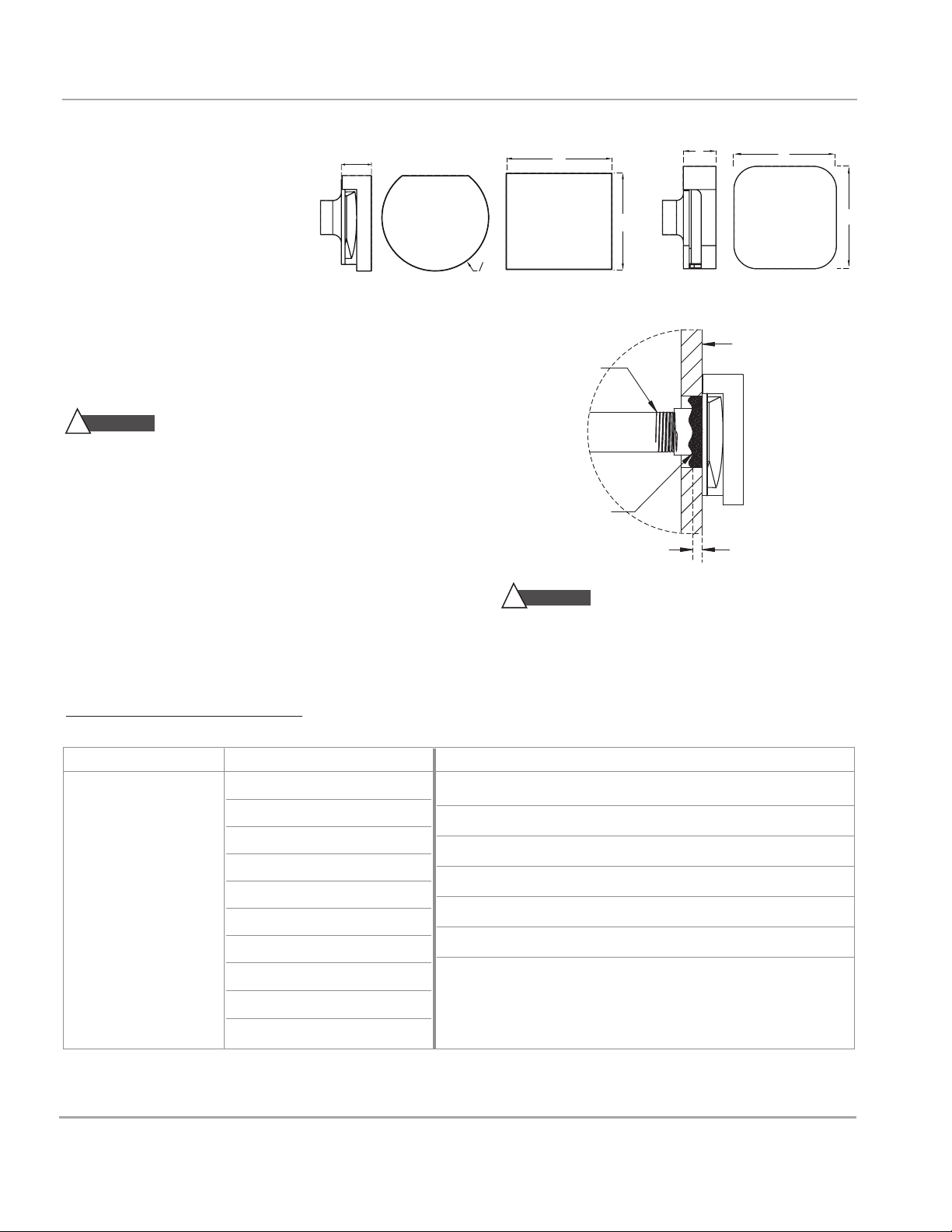
Round & Square Steamhead Installation
(1⁄2" NPT)
IMPORTANT: Do not disassemble steamhead. MrSteam’s steam
head is shipped fully assembled and requires no additional assembly.
CAUTION
!
are very hot, locate the steamhead where incidental contact by
bather with the steamhead or direct steam emission cannot occur.
NOTE: A 1.5” clearance hole around the steam pipe is needed
to mount the steamhead.
Locate steamhead 6-12 inches above floor, except for:
• Tub/shower enclosures, install 6 inches above tub top edge.
• For enclosures with acrylic or other non-heat resistant flooring
install Acrylic Shield Part Number 103938/10398SQ
IMPORTANT NOTE: To preserve steamhead finish,
do not use wrench or other tools to tighten. DO NOT
use abrasive cleansers or chemicals. Use only water
with mild soap and a non-abrasive sponge.
Because the steamhead and direct steam emissions
103937 104040 104104
Round
®
Use Teflon
sealant on pipe threads
equal sealant as required
CAUTION
!
and other non-heat resistant enclosures for recommended
steamhead location. Use Acrylic Shield PN 103938/
103938SQ. See instructions provided with steam shield. (An
acrylic shield is not available for the iSteam steamhead.)
or equal
Steam
Supply P ipe
Apply with silicone or
for moisture seal.
Consult with supplier of acrylic, fiberglass
103937
, Square
104040, 104104
1/8" minimum clearance required
w
hen Acrylic Shield is used. See
installation instructions provided
with the Acrylic Shield
End of pipe to be recessed
1/4" (without Acrylic Shield)
1/8" (with Acrylic Shield)
.
FOR ILLUSTRATIVE PURPOSES ONLY. IMPORTANT NOTE: FOR SAFE AND TROUBLE FREE INSTALLATION visit mrsteam.com
before installation to download the Installation, Operation and Maintenance Manual or refer to the manual provided with the unit.
MODEL FINISH** PROJECT INFORMATION
103937-Round
104040-Square
104104*
* 104104 Steamhead is used for AirTempo, iSteam and black/white facia iTempo and iTempoPlus.
** For AirTempo select black or white with a decorative finish
***iSteam, black/white fascia iTempo and iTempoPlus are provided with matching glass face and chrome trim only.
mr.steam
43-20 34th Street, Long Island City, NY 11101 TEL: 1 800 76 STEAM FAX: 718 472 3256
9410 S. La Cienega Blvd. Inglewood CA 90301 TEL: 1 800 72 STEAM FAX: 310 216 2944
®
Sussman-Automatic Corp®[email protected] www.mrsteam.com
BB Brushed Bronze
BN Brushed Nickel
ORB Oil Rubbed Bronze
PB Polished Brass
SB Satin Brass
PC Polished Chrome
PN Polished Nickel
RAW
Custom Plating
BLK Black***
WH White***
Location:
Architect:
Engineer:
Contractor:
Submitted By:
Date:
Notes:
TS0010 7.17
Page 5
mr.steam
33⁄8”
2
3
⁄4”
7
⁄ 8”
®
Technical Specifications
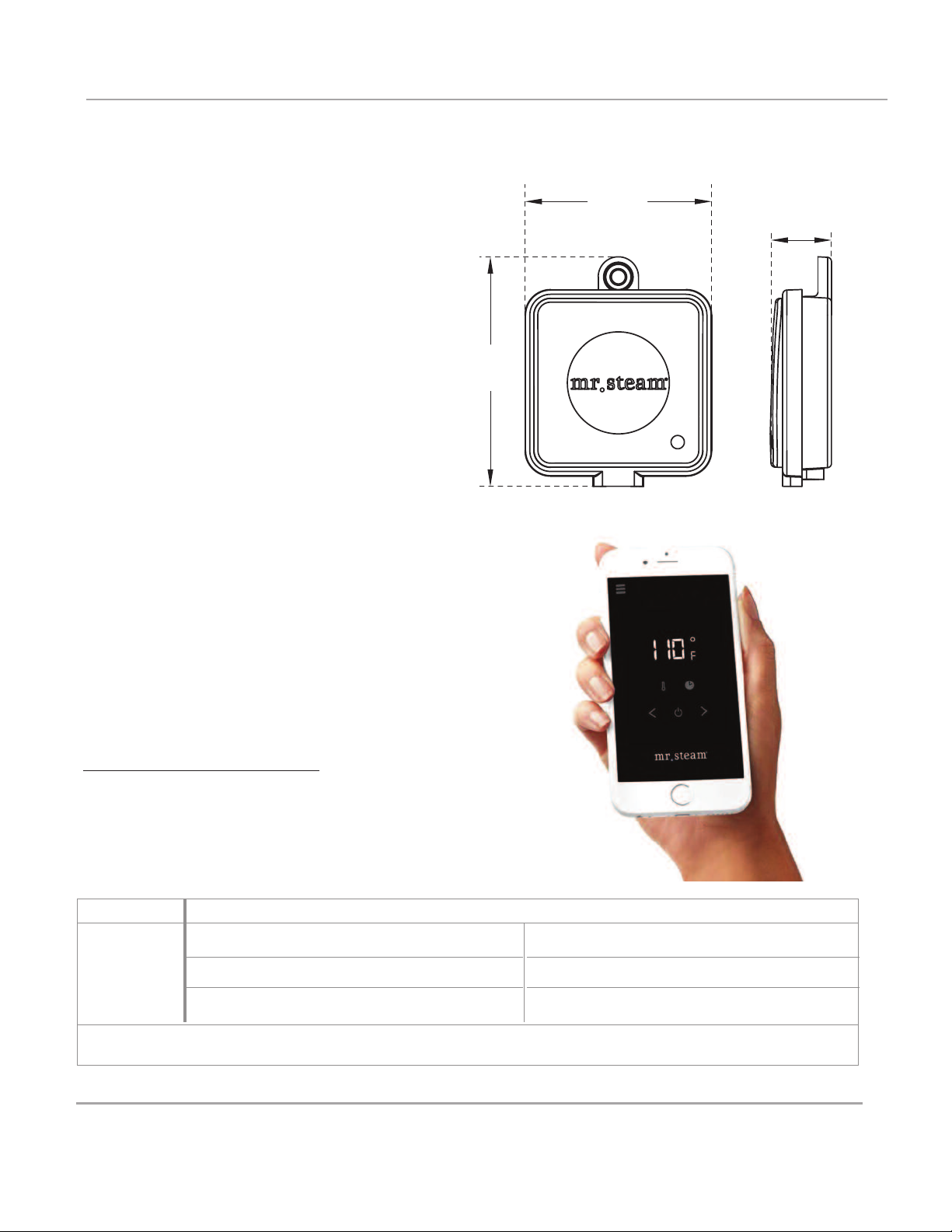
SteamLinx
B O X C O N T E N T
• SteamLinx Generator Module
• SteamLinx Router Module
• 6 foot Ethernet Cord
• Power Adapter
™
SteamLinx
Introducing the latest Mobile Steam Room
Technology, the SteamLinx Mobile System.
SteamLinx allows for seamless control of
essential steam room functionality using
your smart phone or mobile device.
Included in all Dream & Butler Packages.
Works will all MrSteam Controls
App available for download from Google
Play and the App Store
FOR ILLUSTRATIVE PURPOSES ONLY.
IMPORTANT NOTE: FOR SAFE AND TROUBLE FREE INSTALLATION visit
mrsteam.com before installation to download the Installation, Operation and
Maintenance Manual or refer to the manual provided with the unit.
MODEL PROJECT INFORMATION
Location:
Architect:
Engineer:
SteamLinx
Notes:
Contractor:
Submitted By:
Date:
mr.steam
43-20 34th Street, Long Island City, NY 11101 tel: 1 800 76 STEAM fax: 718 472 3256
9410 S. La Cienega Blvd. Inglewood CA 90301 tel: 1 800 72 STEAM fax: 310 216 2944
®
Sussman-Automatic Corp®
[email protected] www.mrsteam.com
TS0077 7.17
Page 6
mr.steam
2
”
5
/
8
”
7
1
/
2
”
1
1
/
4
”
14
1
/
8
”
3
/
4
”
NPT Steam
Outlet Connection
Round
Mounting
Holes
12
1
/
8
”
Slotted
Mounting
Holes
Steam
Outlet
Steam
head
6”-12”
above
floor
STEA M
EMIS S I O N
ZONE
Stea m R o o m
Inte r i o r
STEA M
EMIS S I O N
Cement Board
Thin Set
Finished Wall
Surface
STUD
Steam Outlet Face
Silicone
Silicone
Flush to
1
/
8
”
®
Technical Specifications
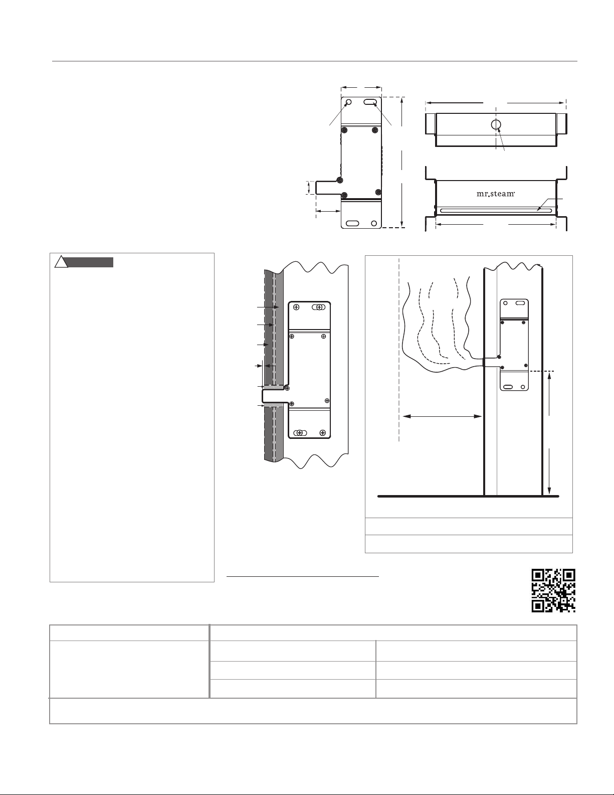
Linear Steamhead
Quiet, even distribution of steam • No moving parts
•
• No field assembly required • Minimal profile
Linear Steamhead Installation
(3⁄4" NPT)
IMPORTANT: Do not disassemble steamhead. MrSteam’s
steamhead is shipped fully assembled and requires no
additional assembly.
Locate steamhead 6-12 inches above floor, except for
tub/shower enclosures; install 6 inches above tub top edge.
CAUTIONS
!
• Because the steamhead and direct
steam emissions are very hot, locate
the steamhead where incidental
contact by bather with the steamhead or direct steam emission
cannot occur.
• Linear Steam Head model 104216 is
suitable for MrSteam generator
models MS90–400, MSSUPER1– 3 and
CT6-CT15.
• Two 104216 linear steamheads must be
used for models MSSUPER4, 5 & 6.
• Using model 104216 for any steam
generator model larger than the
MSSUPER3, or for any non MrSteam
brand generators may result in an
improper installation or hazardous
condition.
• For residential and Day Spa use only.
• Install in a horizontal orientation only.
Installation in a vertical orientation may
concentrate the steam and result in
excessive temperatures.
FOR ILLUSTRATIVE PURPOSES ONLY. IMPORTANT NOTE: FOR SAFE
MODEL PROJECT INFORMATION
104216 For MS90 - MSSUPER3
and CT6-CT15
Two required for SUPER4, 5 and 6.
Notes:
mr.steam
43-20 34th Street, Long Island City, NY 11101 TEL : 1 800 76 STEAM FAX: 718 472 3256
9410 S. La Cienega Blvd. Inglewood CA 90301 TEL: 1 800 72 STEAM FAX: 310 216 2944
®
Sussman-Automatic Corp®[email protected] www.mrsteam.com
AND TROUBLE FREE INSTALLATION visit mrsteam.com or scan the QR code
before installation to download the Installation, Operation and Maintenance
Manual or refer to the manual provided with the unit.
Location:
Architect:
Engineer:
104216
Generator Model Steam Emission Zone
MS90 – MS400, CT6, CT9 18”
SUPER 1 – SUPER3; CT12, CT15 24”
Contractor:
Submitted By:
Date:
TS0067-1 REV 7.17
 Loading...