

Mr. Steam MSCHROMA3WH, MSCHROMA3BK Installation Manual
Installation, Operation, and Maintenance Manual
O
®
AND
UC
UCTIONS
EFER T
ChromaSteam®3
ANUAL PROVIDED WITH PROD
FOR
mr.steam
MPLETE INSTR
®
Feel Good Inc.
AINTENANCE
T
®
IMPORTANT SAFETY INFORMATION
the C
A
of the Chrom
team3 and the surroundin
UCTIONS
READ ME FIRST:
1. Read and follow all instructions within this technical manual.
2. Heed all warnings, cautions, notices, and important notes.
3. Save this technical manual and leave with the homeowner.
ABOUT WARNINGS, CAUTIONS, NOTICES, AND IMPORTANT NOTES:
As you follow the instructions in this technical manual, you will see four types of callouts: WARNINGS, CAUTIONS, NOTICES, and
IMPORTANT NOTES. This blocked information is important for the safe and efficient installation, operation, and maintenance of
the ChromaSteam3. These callouts are described as follows:
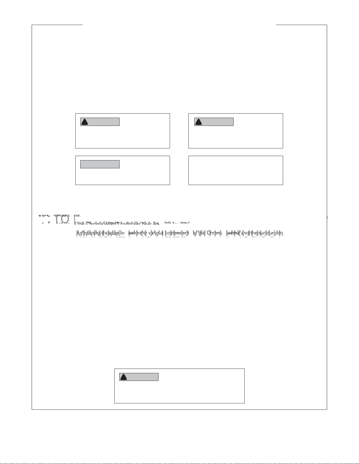
WARNING
!
Indicates a potentially hazardous situation,
which, if not avoided, may result in death
or serious injury.
NOTICE
Indicates a situation, which, if not avoided,
may result in property damage.
CAUTION
!
Indicates a potentially hazardous situation,
which, if not avoided, may result in minor
or moderate injury.
IMPORTANT NOTE
Indicates information that is especially
relevant to a problem-free installation.
SAFETY INSTRUCTIONS:
To prevent personal injury and/or product damage, please read the following important safety instructions carefully before installing
the ChromaSteam3:
• Do not install the ChromaSteam3 controller near any heat sources.
• Clearance and minimum distance between the various components of the ChromaSteam3 and the surrounding structure are
not specified as long as they are sufficient so that the ambient temperature around the apparatus does not exceed 140 °F
(60 °C).
• Do not defeat the safety purpose of the polarized and/or grounding type plug. A polarized plug has two blades, with one
wider than the other. A grounding type plug has two blades and a third grounding prong. The wide blade or the third prong
are provided for your safety. If the provided plug does not fit into your outlet, consult an electrician for replacement of the
obsolete outlet.
• Protect the power cords from being walked on or pinched, particularly at plugs, convenience receptacles, and at the point
where the cords exit from the apparatus.
• Only use attachments/accessories specified by the manufacturer.
• All servicing to be performed by qualified service personnel. Servicing is required when the ChromaSteam3 is damaged in any
way, including when the power-supply cord or plug is damaged, liquid is spilled into or objects fall into the controller, the controller is exposed to rain or moisture, the fixture or controller does not operate normally, or the fixture or controller is dropped.
• Do not disassemble or alter the ChromaSteam3 fixture or controller in any way.
• Clean the ChromaSteam3 fixture and controller with a dry cloth only. Beware of the application of some products commonly
used against corrosion (such as WD-40
age the housing materials of the ChromaSteam3 fixture and controller. Any other materials that may come in contact with the
ChromaSteam3 must be carefully evaluated under end-use conditions for compatibility.
FOR
MPLETE INSTR
®
family products), as some industrial oils can have negative chemical reactions and dam-
AND
AINTEN
NOTE: All information in this technical manual is based on the latest product information available at the time of publication.
Sussman-Automatic Corporation reserves the right to make changes at any time without notice.
WARNING
!
These instructions are for use by qualified service personnel
only. To reduce the risk of electric shock, do not perform
any servicing, other than that contained in these instructions.
2

mr.steam
O
the ju
fi
boxnction box
AND
.............
.
....
the Chrom
control box
the steam
EFER T
®
INSTALLER INSTRUCTIONS
FOR
INSTALLATION, OPERATION, AND MAINTENANCE ChromaSteam
TABLE OF CONTENTS
1. General information ....................................................................................5
Box contents ....................................................................................................... 5
ChromaSteam3 general installation ................................................................... 5
2. Installing the ChromaSteam3 control box ..................................................6
Control box dimensions ..................................................................................... 6
Locating the control box .................................................................................... 7
Installing the control box .................................................................................... 7
3. Installing the ChromaSteam3 fixture ..........................................................8
Fixture dimensions ............................................................................................. 8
Installing the junction box .................................................................................. 9
nstalling the
Installing the fixture .......................................................................................... 11
.
onnecting the ChromaStam3 fixtureo the
4. Connecting the ChromaSteam3 fixture to the control box ......................12
.
5. Connecting the ChromaSteam3 control box to the steam generator ......13
6. ChromaSteam3 specifications ...................................................................14
ontrol box
.....
®
3
HOMEOWNER/END-USER INSTRUCTIONS
7. About ChromaSteam3 ...............................................................................15
8. Operating ChromaSteam3 ........................................................................ 16
9. ChromaSteam3 warranty .......................................................................... 17
®
mr.steam
Sussman-Automatic Corporation® • www.mrsteam.com • hello@mrsteam.com
43-20 34th Street, Long Island City NY 11101 1 800 76 STEAM FAX: 718 472 3256
9410 S. La Cienega Blvd., Inglewood CA 90301 1 800 72 STEAM
FAX: 310 216 2944
PUR 100515 REV 6.17
3

mr.steam
O
page lef
blank intentio
AND
UC
UCTIONS
®
INSTALLATION, OPERATION, AND MAINTENANCE ChromaSteam
INSTALLER
®
3
EFER T
This page left blank intentionally
ANUAL PROVIDED WITH PROD
FOR
MPLETE INSTR
AINTENANCE
T
4
®
o
atio
long. Ensure that
ChromaSteam3
m
and con
a
to purchase a
box are located accord
optional 60-foot cable (
e
0 68 60))
mr.steam
mr.steam
®
INSTALLATION, OPERATION, AND MAINTENANCE ChromaSteam
INSTALLATION, OPERATION, AND MAINTENANCE ChromaSteam
INSTALLER INSTRUCTIONS
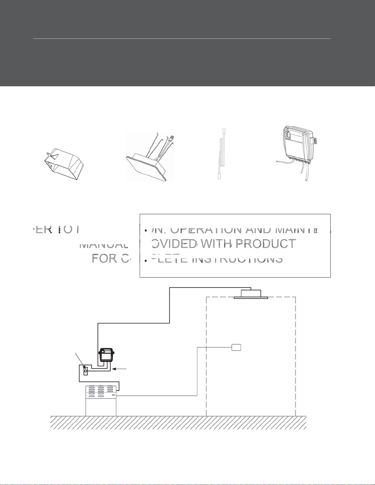
1. General information
Box contents
®
®
3
3
Junction box
ChromaSteam3
fixture
ChromaSteam3 general
installation
Figure 1 shows how the ChromaSteam3
fixture and control box interconnect with
each other, and with the steam generator
and iSteam3.
ati
Grounded
wall
outlet
team gen
ChromaSteam3 cable (30 ft)
ator
ChromaSteam3
control box
30-foot
ChromaSteam3 cable
IMPORTANT NOTES
• The included ChromaSteam3 control cable is 30 feet long. Ensure that
he in
ded ChromaSteam3 control cle is 30 feelong. Ensure that
the ChromaSteam3 fixture and control box are located accordingly. Contact MrSteam to purchase an optional 60-foot cable (Part No.
y. Contact MrStea
104268-60).
• The cord between the control box and steam generator is 5 feet long.
• ChromaSteam3 only works with iSteam3.
to purchase
optional 60-foot cable (P
ChromaSteam3
fixture
iSteam3
ChromaSteam3
control box
All drawings are for illustrative purposes only.
Steam
generator
Power cord
In-room control cable (30/60 ft)
(dry)
Figure 1
5
STEAM ROOM
(wet)
mr.steam
A
D
AAA
A V
OD
T
T
RUCTIO
T
®
INSTALLATION, OPERATION, AND MAINTENANCE ChromaSteam
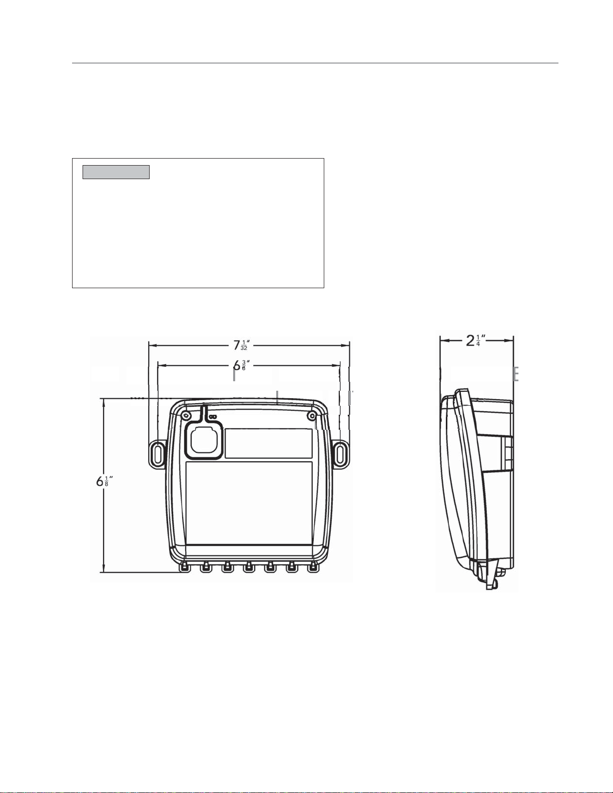
2. Installing the ChromaSteam3 control box
Control box dimensions
NOTICE
®
3
INSTALLER
EFER TO IN
• To prevent product or property damage, do not expose
control box to temperatures above 140 °F (60 °C). Do not
locate control box in an attic or any location where ambient temperatures may exceed 140 °F (60 °C).
• Do not locate control box next to heat sources, such as
hot air registers, air conditioner condensers, etc.
• The control box powers the ChromaSteam3 fixture with
5VDC 1.6A maximum.
ALLAT
N,
PER
ION
H TPR
AN
AINT
NANCE
All drawings are for illustrative purposes only.
Figure 2
Figure 3
6
 Loading...