

Page 1
INSTRUCTIONS FOR USE
85 Combi, 95 Combi, 105 Combi for
8211-7060-81
INSTRUCTIONS FOR USE
MODE D’EMPLOI
GEBRUIKSAANWIJZING
NÁVOD K POU®ITÍ
EN.....5
FR......9
NL.. 13
CS... 17
Mountfield 2000, 4000 and XK series
Page 2
2
125 Combi Pro
4000 series 4WD, 2000 series
A
B
C
(D)
4000 series 4WD
A
B
C
4000 series 2WD
G
F
E
I
H
4000 series 2WD
3
5
7
1
4
6
8
2
Page 3
3
2000 series
17”
16”
1/3
11
13
15
9
12
14
16
10
Page 4
4
90°
K
K
4000 series 4WD
P
PQ
Q
45 Nm
K
K
2000 series
19
21
17
20
22
18
Page 5
5
ENGLISH
EN
1 GENERAL
This symbol indicates WARNING. Serious personal injury and/or damage to
property may result if the instructions
are not followed carefully.
You must read these instructions for use
and the machine’s safety instructions
carefully.
1.1 Symbols
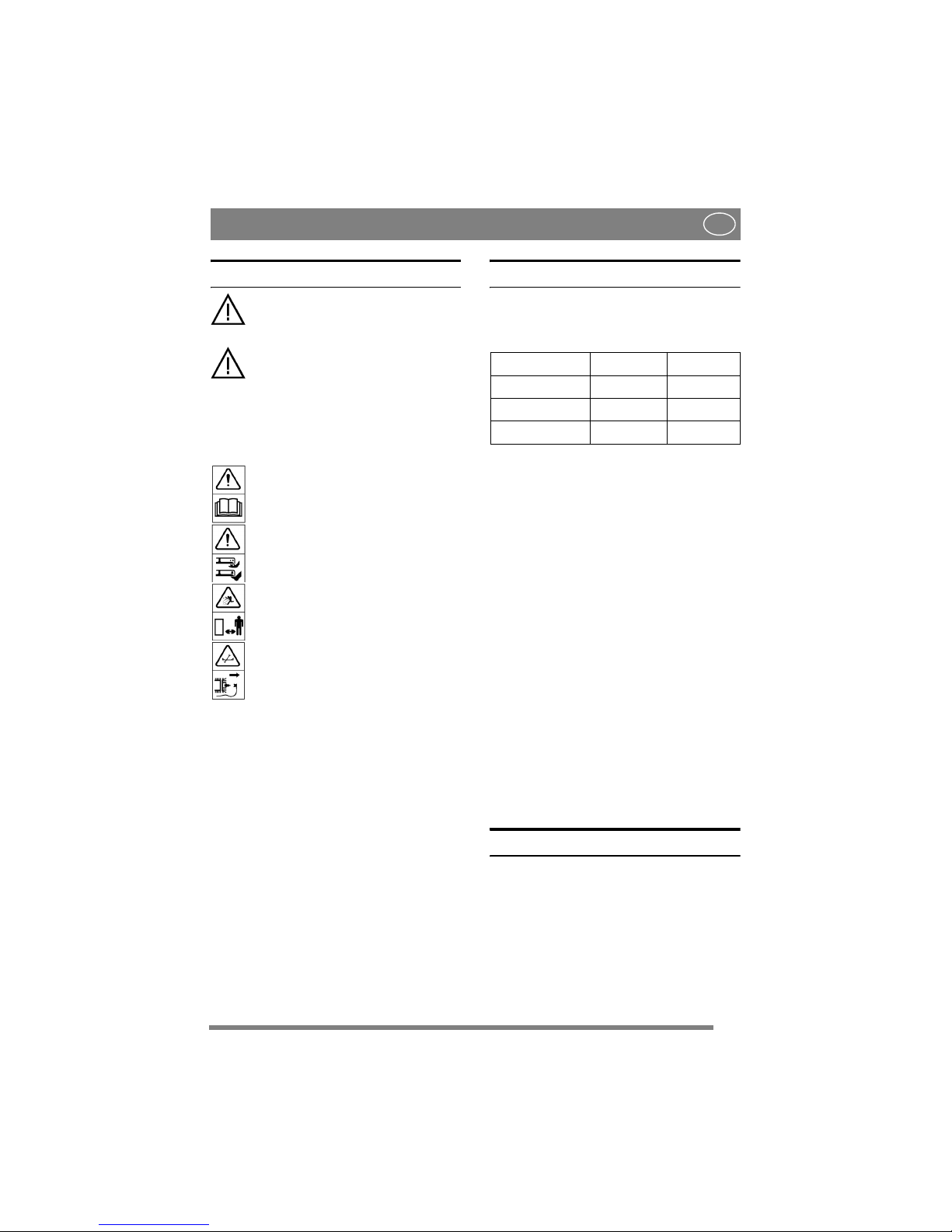
The following symbols appear on the machine.
They are there to remind you of the care and attention required in use.
This is what the symbols mean:
Warning!
Read the instruction manual and the safety
manual before using the machine.
Warning!
Do not insert your hands or feet under the
cover when the machine is in operation.
Warning!
Watch out for discarded objects. Keep onlookers away.
Warning!
Before starting repair work, remove the
spark plug cable from the spark plug.
1.2 References
1.2.1 Figures
The figures in these instructions for use are numbered 1, 2, 3, etc.
Components shown in the figures are marked A, B,
C, etc.
A reference to component E in figure 5 is written
“5:E”.
1.2.2 Headings
The headings in these instructions for use are numbered in accordance with the following example:
“2.3.2” is a subheading to “2.3” and is included under this heading.
When referring to headings, only the number of the
heading is normally specified. E.g. “See 2.3.2”.
2 DESCRIPTION
2.1 General
The cutting deck is intended for use on GGP’s
front mowers according to the table below.
The cutting deck is supplied in one of the following versions:
• With manual adjustment of cutting height.
• With electrical adjustment of cutting height.
2.2 Controls
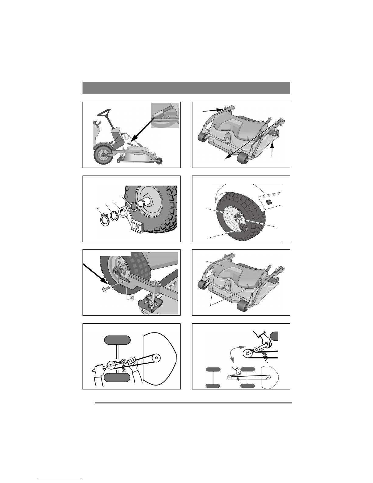
2.2.1 Cutting height adjustment
The cutting height can be adjusted between 25 and
90 mm.
The setting can be adjusted to a number of fixed
positions using the lever. See fig. 2.
2.2.2 Incline forwards
The rear section of the cutting deck can be raised
12 mm by moving the two pins down one hole
from the basic setting. See fig. 2.
2.2.3 Rear mounting
The cutting deck’s rear section is secured with the
pins in fig. 2.
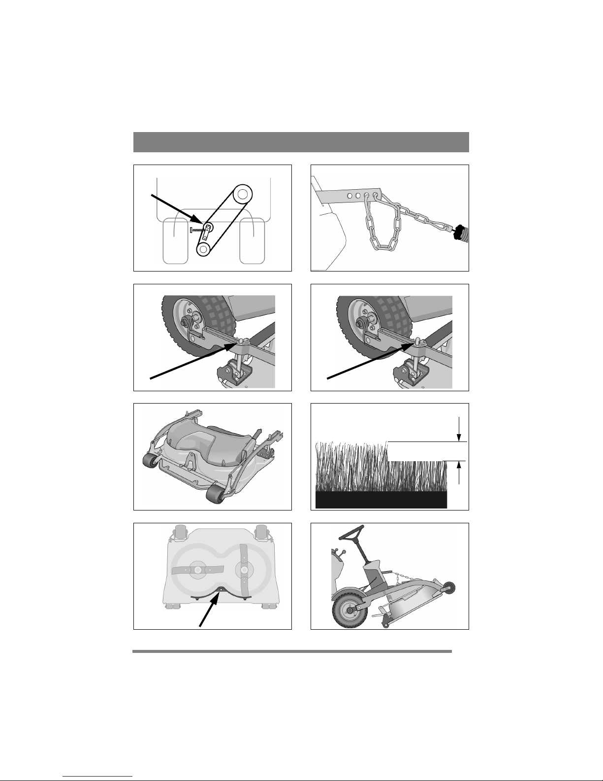
2.2.4 Mounting in implement lifter
The deck is mounted in the implement lifter with a
chain and snap hooks.
One snap hook is intended for the working position
and can be moved in the chain links to set the lifting force. See fig. 10.
The other snap hook is intended for the washing
position.
3 ASSEMBLY
3.1 Assembly on 4WD 4000-series
and 2000-series
1. Place the deck in position in front of the ma-
chine.
2. Check that the deck mounts are installed on the
machine as follows.
• Washer (3:D). Only machines up to and including 2006.
• Deck mount (3:C).
• Washer (3:B).
• Circlip (3:A).
Cutting deck 2000 series 4000 series
85 Combi X
95 Combi X X
105 Combi X
Page 6
6
ENGLISH
EN
3. Screw the arms into each other. See fig. 5.
4. Remove the belt cover (6:H) by loosening the
screws 6:I.
5. Set the maximum cutting height.
6. Loosen the belt guide screws (21, 22:K) a
couple of turns and work off the belt from the
cutting deck’s pulley.
7. Locate the belt around the machine’s belt pulley
and cutting deck’s pulley.
8. Tighten the belt guide screws (21, 22:K).
9. Tension the belt as follows.
4WD 4000-series
:
Grip the belt tensioner’s lever with your left
hand. Pull the lever and apply the tensioner to
the outside of the belt with your right hand. See
fig.7.
2000-series
:
Tension the belt with the belt idler. The belt
idler should be on the inside of the belt and pull
out to the left (viewed from the driver’s position). See fig. 9.
10.Install the belt cover (6:H) with the screws
(6:I).
11.Suspend the unit in the implement lifter. See
fig. 10.
12.Perform the basic setting. See 3.4.
3.2 Assembly on 2WD 4000-series
1. Place the deck in position in front of the machine.
2. Check that the deck mounts are installed on the
machine as follows.
• Deck mount (4:G).
• Washer (4:F).
• Lock pin (4:E).
3. Screw the arms into each other. See fig. 5.
4. Set the maximum cutting height.
5. Locate the belt around the machine’s belt pulley.
6. Tension the belt with the belt idler. The belt
idler should be on the left side of the belt
viewed from the driver’s position. See fig. 8.
7. Suspend the unit in the implement lifter. See fig.
10.
8. Perform the basic setting. See 3.4.
3.3 Tyre pressure
Adjust the tyre pressures according to the table below.
3.4 Basic setting
In order for the cutting deck to cut optimally, the
correct basic setting is required. The deck is in the
basic setting when its rear edge is 5 mm above its
front edge. This means that the deck is inclined
forwards.
Move the deck to the basic setting by lifting and
securing as follows.
On machines with 17” wheels:
Install the washers
and the pins in the top hole. See fig. 11.
On machines with 16” wheels:
Install the washers
and the pins in the middle hole. See fig. 12.
4 USING THE MACHINE
Check that the grass that is to be cut is
completely free of foreign objects such
as stones etc.
4.1 Cutting height
The best cutting results are achieved when the
when the top third of the grass is cut off. I.e. 2/3 of
the length of the grass remains. See fig. 14.
If the grass is long and has to be cut significantly,
cut twice using different cutting heights.
Do not use the lowest cutting heights if the lawn
surface is uneven. This would entail a risk of the
blades being damaged against the surface and the
lawn’s top layer of soil being removed.
4.2 Incline
The cutting deck’s rear section can be lifted so that
the deck has a greater forward incline than that
provided by the basic setting. This incline affects
the cutting results as follows.
4.2.1 Basic setting
When the deck is in the basic setting, the best
mulching effect and good dispersion of the cut
grass are achieved. The basic setting is recommended for normal grass. See 3.4.
4.2.2 Greater inclination
When the cutting deck is inclined forwards, the
“Multiclip” effect is reduced while the cut grass is
dispersed better.
Inclining forwards is recommended for thicker
grass.
4.3 Mowing advice
In order to achieve optimum mowing results, follow the advice below:
• Cut frequently.
• Run the engine at full throttle.
• The grass should be dry.
• Use sharp blades.
• Keep the underside of the cutting deck clean.
Machine Pressure (bar/psi)
Front Rear
4000-series 0,6/9 0,4/6
2000-series
0,4/6 1,2/17
Page 7
7
ENGLISH
EN
4.4 Composting/rear ejection
The deck can cut grass in two ways:
• Compost the grass into the lawn.
• Eject the grass behind the deck.
The deck is set for composting on delivery. In order to eject the grass behind the deck, the plug in
fig. 15 must be removed.
Set the deck in cleaning or service position (see
5.2/5.3) in order to remove/install the plug.
5 MAINTENANCE
5.1 Preparation
All service and all maintenance must be carried out
on a stationary machine with the engine switched
off.
Prevent the machine from rolling by always applying the parking brake.
Stop the engine.
Prevent unintentional starting of the
engine by disconnecting the spark plug
cable from the spark plug and removing the ignition key.
5.2 Washing position
1. Activate the parking brake.
2. Set the implement lifter in transport position.
3. Set the highest cutting height.
4. Detach the rear section of the deck on the right
and left-hand side as follows:
A. Lift up the left-hand rear section of the
deck slightly to reduce the load from the
cotter pin.
B. Remove pins and washer. See fig. 2.
C. Remove the right-hand cotter pin and
washer in the same way.
5. Grip the front edge of the deck and lift up. Hook
on the chain so that the deck is pointing diagonally upwards. See fig. 16.
It is absolutely forbidden to start the
engine when the deck is in the washing
position.
Reset the deck according to 3.1.
5.3 Service position, 4WD 4000-se-
ries and 2000-series
1. Activate the parking brake.
2. Set the maximum cutting height.
3. See fig. 2. Detach the rear section of the deck on
the right and left-hand side as follows:
A. Lift up the left-hand rear section of the
deck slightly to reduce the load from the
cotter pin.
B. Remove pins and washer.
C. Remove the right-hand cotter pin and
washer in the same way.
4. Remove the belt cover (6:H) by loosening the
screws 6:I.
5. Unhook the belt as follows.
4WD 4000-series
:
Grip the belt tensioner’s lever with your left
hand. Pull the lever and unhook with your right
hand. See fig. 7.
2000-series
:
Unhook the belt idler from the belt. See fig. 9.
6. Loosen the belt guide screws (21, 22:K) a
couple of turns and work off the belt from the
cutting deck’s pulley.
7. Force the belt off the deck’s pulley.
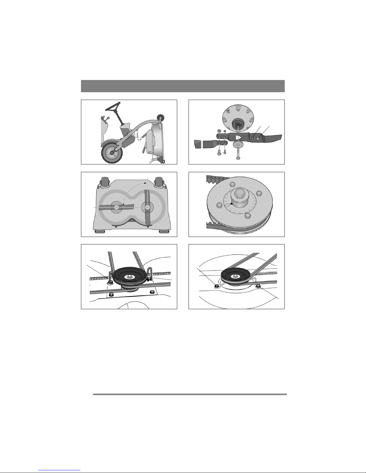
8. Grip the front edge of the deck and lift up. Lift
until the deck is completely vertical and rest the
rear edge on the ground. See fig. 17.
Reset the deck according to 3.1.
5.4 Service position,
2WD 4000-series
1. Activate the parking brake.
2. Set the maximum cutting height.
3. See fig. 2. Detach the rear section of the deck on
the right and left-hand side as follows:
A. Lift up the left-hand rear section of the
deck slightly to reduce the load from the
cotter pin.
B. Remove pins and washer.
C. Remove the right-hand cotter pin and
washer in the same way.
4. Release the belt tension by unhooking the belt
idler from the belt. See fig. 9.
5. Force the belt off the machine’s pulley.
6. Grip the front edge of the deck and lift up. Lift
until the deck is completely vertical and rest the
rear edge on the ground. See fig. 17.
Reset the deck according to 3.2.
5.5 Cleaning
The underside of the deck must be cleaned after
each use.
Set the deck in washing position.
Clean the underside of the deck carefully. Use wa-
ter and a brush.
When the surfaces are completely dry and clean,
touch up the paintwork. Use durable yellow paint
intended for metal outdoors.
Page 8

8
ENGLISH
EN
5.6 Blades
5.6.1 Safety
To reduce the risk of accidental injury in the event
of a collision and to protect important parts in the
cutting deck, a force limiter is integrated as follows.
• Shear bolts between blades and blade bar.
• Torque limiting between gear wheels and blade
shaft.
• Possibility of positive drive belt slipping on the
plastic gear wheels.
5.6.2 Replacing blades
Wear protective gloves when changing
blade(s) to avoid cutting yourself.
Check that the blades are always sharp. This produces the best cutting results. The blades should be
replaced once a year.
Always check the blades after a collision. If the
blade system has been damaged, defective parts
should be replaced.
Always use genuine spare parts. Nongenuine spare parts can entail a risk of
injury, even if they fit the machine.
The blades are replaceable. When replacing, both blades on the same blade bar must be replaced to avoid imbalance.
Attention!
Note the following when reassembling:
• The blades and blade bar must be installed as in
fig 18.
• The blades can be turned 1/3 of a turn in their
mountings. Select positions so that the blades
are offset 90° from each other. See “5.6.3” be-
low.
Tightening torque:
Screws (18:P) - 45 Nm
Shear bolts (18:Q) - 9.8 Nm
In the event of a collision, the shear bolts (18:Q)
can break and the blades bend back. If this has happened, install genuine shear bolts and tighten as
above.
5.6.3 Synchronising, blades
The deck has synchronised blades.
If one of the blades has struck a solid object (e.g. a
stone), the synchronisation may be altered. This
entails a risk of the blades colliding with each other.
Correctly synchronised blades must be offset 90°
from each other. See fig. 19.
Always check synchronisation after a collision.
If the blades are not synchronised, one or more of
the following faults may have occurred in the cutting deck:
• The positive drive belt has slipped on the gear
wheels.
• Torque limiting between gear wheels and blade
shaft has deployed. The arrows in fig. 20 must
be opposite each other for an intact deck. When
torque limiting has deployed, the arrows are not
opposite each other.
• The blade member is incorrectly installed on
the blade shaft. Can be installed in three different positions. See 18:R.
In the event of incorrect synchronisation according
to the two first alternatives, contact an authorised
GGP workshop for repair.
6 SPARE PARTS
GGP genuine spare parts and accessories are designed specifically for GGP machines. Please note
that ‘non-genuine’ spare parts and accessories
have not been checked or approved by GGP:
The use of such parts and accessories
can affect the function and safety of the
machine. GGP accepts no responsibility
for damage or injuries caused by such
products.
7 DESIGN REGISTRATION
This product or parts thereof is covered by the following design registration:
Sweden: 66 166
Germany: 499 11 740.9
France: 577 251-253, 577 439-443
USA: 435 564
GGP reserves the right to make alterations to the
product without prior notification.
Page 9

9
FRANÇAIS
FR
1 GÉNÉRALITÉS
Ce symbole est un AVERTISSEMENT.
Risque de blessure ou de dégât matériel
en cas de non-respect des instructions.
Lire attentivement les instructions et les
consignes de sécurité avant d’utiliser la
machine.
1.1 Symboles
Les symboles suivants figurent sur la machine. Ils
attirent votre attention sur les dangers d’utilisation
et les mesures à respecter.
Explication des symboles:
Attention!
Lire le mode d’emploi et le manuel de sécurité avant d’utiliser la machine.
Attention!
Ne pas mettre les mains ou les pieds sous
la machine en fonctionnement.
Attention!
Attention aux projections. Travailler à une
distance suffisante de toute présence.
Attention!
Avant toute réparation, débrancher le câble d’alimentation de la bougie.
1.2 Références
1.2.1 Numérotation
Dans les instructions qui suivent, les figures sont
numérotées 1, 2, 3, etc.
Les composants illustrés sont indiqués par A, B, C,
etc.
Une référence renvoyant à l’élément E de la figure
5 sera indiquée « 5:E ».
1.2.2 Titres
Les titres sont numérotés selon l’exemple suivant:
« 2.3.2 » est un sous-titre de « 2.3 ».
En principe, lorsqu’on renvoie à un titre, seul son
numéro est indiqué, par ex. « Voir 2.3.2 ».
2 DESCRIPTION
2.1 Généralités
Le plateau de coupe est conçu pour les tondeuses
GGP à plateau monté à l’avant (voir tableau cidessous).
Deux versions sont disponibles:
• Avec réglage manuel de la hauteur de coupe.
• Avec réglage électrique de la hauteur de coupe.
2.2 Commandes
2.2.1 Réglage hauteur de coupe
La hauteur de coupe se règle de 25 à 85 mm.
Un levier permet de régler la hauteur de coupe sur
plusieurs positions (voir fig. 2).
2.2.2 Inclinaison vers l’avant
La partie arrière du plateau de coupe peut être rehaussée de 12 mm en plaçant les deux goupilles un
trou plus bas que la position d’origine (voir fig. 2).
2.2.3 Montage à l’arrière
La partie arrière du plateau de coupe est fixée à
l’aide des deux goupilles illustrées à la fig. 2.
2.2.4 Montage du dispositif de levage des
accessoires
Le plateau est monté dans le dispositif de levage à
l’aide d’une chaîne et de crochets à ressort.
L’un des crochets est prévu pour la position de travail et peut être fixé sur divers maillons de la
chaîne pour régler la force de levage (voir fig. 10).
L’autre crochet à ressort sert à la position de nettoyage.
3 ASSEMBLAGE
3.1 Assemblage on 4WD 4000-se-
ries and 2000-series
1. Positionner le plateau de coupe devant la machine.
2. Vérifier que les supports du plateau sont installés sur la machine comme suit :
• Rondelle (3:D). Uniquement pour les ma-
chines jusqu’en 2006 compris.
• Montant du plateau (3:C).
• Rondelle (3:B).
• Circlip (3:A).
Plateau de
coupe
2000 series 4000 series
85 Combi X
95 Combi X X
105 Combi X
Page 10

10
FRANÇAIS
FR
3. Visser les bras l’un dans l’autre. Voir fig. 5.
4. Retirer le carter de courroie (6:H) en retirant les
vis 6:I.
5. Régler la hauteur maximale de coupe.
6. Desserrer de quelques tours les vis du guidecourroie (21, 22:K) et dégager la courroie de la
poulie du plateau de coupe.
7. Passer la courroie sur la poulie de la machine,
puis sur la poulie du plateau de coupe.
8. Serrer les vis du guide-courroie (21, 22:K).
9. Tendre la courroie comme suit.
4WD 4000-series
:
Saisir de la main gauche le levier de tension de
la courroie. Tirer le levier et appliquer le tendeur sur l’extérieur de la courroie, à l’aide de la
main droite Voir fig.7.
2000-series
:
Tendre la courroie au moyen du tendeur. Le tendeur doit se trouver du côté intérieur de la courroie et se tirer vers la gauche (par rapport au
sens de la marche). Voir fig. 9.
10.Remettre le carter (6:H) en place et les visser
(6:I).
11.Suspendre l’unité dans le dispositif de levage
des accessoires. Voir fig. 13.
12.Procéder aux réglages de base du plateau de
coupe. Voir 3.4.
3.2 Assemblage 2WD 4000-series
1. Positionner le plateau de coupe devant la machine.
2. Vérifier que les supports du plateau sont installés sur la machine comme suit :
• Montant du plateau (4:G).
• Rondelle (4:F).
• Goupille (4:E).
3. Visser les bras l’un dans l’autre. Voir fig. 5.
4. Régler la hauteur de coupe maximum.
5. Faire passer la courroie autour de la poulie de la
machine.
6. Tendre la courroie comme suit.
Tendre la courroie au moyen du tendeur. Vu
dans le sens de la marche, le tendeur doit se
trouver sur la gauche de la courroie. Voir fig. 8.
7. Suspendre l’unité dans le dispositif de levage
des accessoires. Voir fig. 10.
8. Procéder aux réglages de base du plateau de
coupe. Voir 3.4.
3.3 Pression des pneus
Adapter la pression des pneus conformément au
tableau ci-dessous.
3.4 Réglage de base
Pour une efficacité maximale, le plateau de coupe
doit être initialement réglé de manière correcte. Le
plateau est en position de base lorsque le bord arrière est 5 mm plus haut que le bord avant. Le plateau est donc incliné vers l’avant.
Mettre le plateau de coupe en position de base en
le levant et en le sécurisant comme suit.
Machines à roues 17” :
Placer les rondelles et les
goupilles dans le trou du haut. Voir fig. 11.
Machines à roues 16” :
Placer les rondelles et les
goupilles dans le trou du centre. Voir fig. 12.
4 UTILISATION
Vérifier que l’herbe à tondre est exempte de pierres et autres corps
étrangers.
4.1 Hauteur de coupe
Les meilleurs résultats de tonte s’obtiennent en ne
coupant que le tiers supérieur de l’herbe, c’est-àdire en laissant les 2/3 de la longueur (voir fig. 14).
Lorsque l’herbe est haute et doit être coupée
courte, effectuer deux passage à des hauteurs de
coupe différentes.
Ne pas utiliser les positions de coupe inférieures
sur des surfaces irrégulières pour ne pas endommager les lames ni racler la couche supérieure du
sol.
4.2 Inclinaison
La partie arrière du plateau de coupe se soulève
pour augmenter l’inclinaison vers l’avant par rapport au réglage de base. L’augmentation de l’inclinaison influence la tonte comme suit:
4.2.1 Réglage de base
Un plateau en position de base offre le meilleur effet de mulching et une bonne dispersion de l’herbe
coupée. Le réglage de base est recommandé pour
l’herbe normale (voir 3.4).
4.2.2 Inclinaison plus forte
Lorsque le plateau est incliné vers l’avant, l’effet
“Multiclip” est réduit mais la dispersion de l’herbe
coupée est améliorée.
L’inclinaison vers l’avant est recommandée pour
l’herbe épaisse.
4.3 Conseils de tonte
Conseils pour une tonte optimale:
• Tondre fréquemment.
• Faire tourner le moteur à plein régime.
• L’herbe doit être sèche.
• Utiliser des lames affûtées.
• Garder propre le dessous du plateau de coupe.
Machine Pression (bar/psi)
Avant Arrière
4000-series 0,6/9 0,4/6
2000-series
0,4/6 1,2/17
Page 11

11
FRANÇAIS
FR
4.4 Compostage/éjection arrière
Le plateau peut tondre de deux manières différentes :
• En composant l’herbe dans la pelouse.
• En éjectant l’herbe par l’arrière.
À la livraison, le plateau de coupe est réglé pour le
compostage. Pour éjecter l’herbe à l’arrière, il faut
retirer le bouchon illustré à la fig. 15.
Régler le plateau en position de nettoyage ou de
maintenance pour enlever ou remettre le bouchon.
Voir 5.2/5.3.
5 ENTRETIEN
5.1 Préparation
Les interventions d’entretien et de maintenance
doivent être effectuées sur une machine à l’arrêt
dont le moteur est coupé.
Bloquer la machine en serrant le frein à
main.
Arrêter le moteur.
Déconnecter le câbles de bougie et retirer la clé de contact pour éviter tout démarrage intempestif.
5.2 Position de nettoyage
1. Serrer le frein de stationnement.
2. Mettre le dispositif de levage en position de
transport.
3. Régler la hauteur de coupe sur la position maximale.
4. Détacher la section arrière du plateau, à gauche
et à droite, de la manière suivante :
A. Soulever légèrement la partie gauche du
plateau pour réduire la charge sur la
goupille.
B. Retirer les goupilles et les rondelles. Voir
fig. 2.
C. Répéter l’opération à droite.
5. Saisir l’avant du plateau et soulever. Accrocher
la chaîne de manière à ce que le plateau soit
soulevé en diagonale (voir fig. 16).
Il est absolument interdit de démarrer
le moteur avec le plateau en position de
nettoyage.
Ré-assembler le plateau conformément au chapitre
“3.1”.
5.3 Position de maintenance , 4WD
4000-series et 2000-series
Exemple de connexion de plateau fixe, voir 3:C et
4:G.
1. Activer le frein de stationnement.
2. Régler la hauteur de coupe maximum.
3. Voir fig. 2. Détacher la section arrière du plateau, à gauche et à droite, de la manière
suivante :
A. Soulever légèrement la partie gauche du
plateau pour réduire la charge sur la
goupille.
B. Retirer les goupilles et les rondelles.
C. Répéter l’opération à droite.
4. Remettre le carter (6:H) en place et les visser
(6:I).
5. Relâcher la tension de la courroie comme suit.
4WD 4000-series
:
Saisir de la main gauche le levier de tension de
la courroie. Tirer le levier et décrocher le dispositif de tension à l’aide de la main droite. Voir
fig. 7.
2000-series
:
Retirer de la courroie le dispositif de tension.
Voir fig. 9.
6. Desserrer de quelques tours les vis du guidecourroie (21, 22:K) et dégager la courroie de la
poulie du plateau de coupe.
7. Décrocher la courroie de la poulie de la machine.
8. Saisir l’avant du plateau et soulever. Soulever le
plateau complètement à la verticale et laisser reposer le bord arrière sur le sol. Voir fig. 20.
Ré-assembler le plateau conformément au chapitre
3.1.
5.4 Position de maintenance , 2WD
4000-series
Exemple de connexion de plateau fixe, voir 3:C et
4:G.
1. Activer le frein de stationnement.
2. Régler la hauteur de coupe maximum.
3. Voir fig. 2. Détacher la section arrière du plateau, à gauche et à droite, de la manière
suivante :
A. Soulever légèrement la partie gauche du
plateau pour réduire la charge sur la
goupille.
B. Retirer les goupilles et les rondelles.
C. Répéter l’opération à droite.
4. Détendre la courroie en retirant le dispositif de
tension. Voir fig. 9.
5. Décrocher la courroie de la poulie de la machine.
6. Saisir l’avant du plateau et soulever. Soulever le
plateau complètement à la verticale et laisser reposer le bord arrière sur le sol. Voir fig. 17.
Ré-assembler le plateau conformément au chapitre
3.2.
Page 12

12
FRANÇAIS
FR
5.5 Nettoyage
Nettoyer le dessous du plateau de coupe après
chaque utilisation.
Mettre le plateau en position de nettoyage.
Nettoyer avec soin le dessous à l’aide d’une brosse
et d’eau.
Une fois les surfaces totalement sèches et propre,
retoucher les éclats de peinture à l’aide d’une peinture jaune durable spéciale pour les métaux utilisés
à l’extérieur.
5.6 Lames
5.6.1 Sécurité
Pour réduire le risque de blessure accidentelle en
cas de collision et pour protéger les éléments importants du plateau de coupe, un limiteur de force
est intégré :
• Boulons de cisaillement entre les lames et la
barre.
• Limiteur de couple entre les engrenages et l’axe
des lames.
• Possibilité de patinage de la courroie d’entraînement positif sur les engrenages en plastique.
5.6.2 Remplacement des lames
Porter des gants de protection pour
changer les lames.
Les lames doivent toujours rester tranchantes pour garantir un bon résultat de coupe.
Remplacer les lames tous les ans.
Toujours vérifier l’état des lames après un impact.
Si les lames sont endommagées, remplacer les éléments défectueux.
Utiliser exclusivement des pièces
d’origine. L’utilisation de pièces de re-
change d’autres marques, même si elles
s’adaptent à la machine, peut se révéler
dangereuse.
Les lames sont remplaçables. Toujours remplacer
les deux lames montées sur une même barre pour
éviter les déséquilibres.
Attention !
Lors du remontage, veiller aux points suivants:
• Monter les lames et la barre comme illustré à la
fig. 18.
• Les lames peuvent effectuer un tiers de tour
dans leur logement. Positionner les lames de
manière à ce qu’elles soient à 90° l’une par rap-
port à l’autre. Voir « 5.6.3 » ci-dessous.
Couple de serrage:
Vis (18:P) - 45 Nm
Boulons de cisaillement (18:Q) – 9,8 Nm
En cas de collision, les boulons de cisaillement
(18:Q) cassent et les lames se replient. Le cas
échéant, remplacer par des boulons de cisaillement
d’origine et serrer comme indiqué ci-dessus.
5.6.3 Synchronisation des lames
Les lames du plateau fonctionnent de manière synchronisée.
Si l’une des lames percute un objet solide (par ex.
une pierre), elles peuvent se désynchroniser. Il existe alors un risque que les lames entrent en collision l’une avec l’autre.
Des lames correctement synchronisées doivent
être décalées de 90° l’une par rapport à l’autre Voir
fig. 19.
Toujours vérifier la synchronisation après un impact.
En cas de désynchronisation des lames, les problèmes suivants peuvent survenir au niveau du plateau de coupe :
• La courroie d’entraînement positif a glissé sur
les engrenages.
• Le limiteur de couple s’est activé entre les engrenages et l’axe des lames. Pour protéger le
plateau, les flèches de la fig. 20 doivent indiquer des directions opposées. Lorsque le limiteur de couple est activé, les flèches ne sont
pas dans des directions opposées.
• Le longeron de lame est mal installé sur l’axe. Il
peut s’installer dans trois positions différentes.
Voir 18:R.
En cas de désynchronisation des lames pour l’un
des deux motifs cités, contacter un centre agréé
GGP pour procéder aux réparations requises.
6 PIÈCES DE RECHANGE
Les pièces de rechange et accessoires d’origine
GGP sont spécifiquement conçus pour les machines GGP. Les pièces de rechange et accessoires
d’autres marques n’ont été ni testés ni approuvés
par GGP.
L’utilisation de pièces et accessoires
d’autres marques peut affecter le fonctionnement de la machine et en compromettre la sécurité. GGP décline toute
responsabilité pour les dégâts ou blessures occasionnés par ces produits.
7 ENREGISTREMENT
Ce produit et les pièces qui le composent sont enregistrés sous le n°:
EG 000503107
GGP se réserve le droit de modifier le produit sans
avis préalable.
Page 13

13
NEDERLANDS
NL
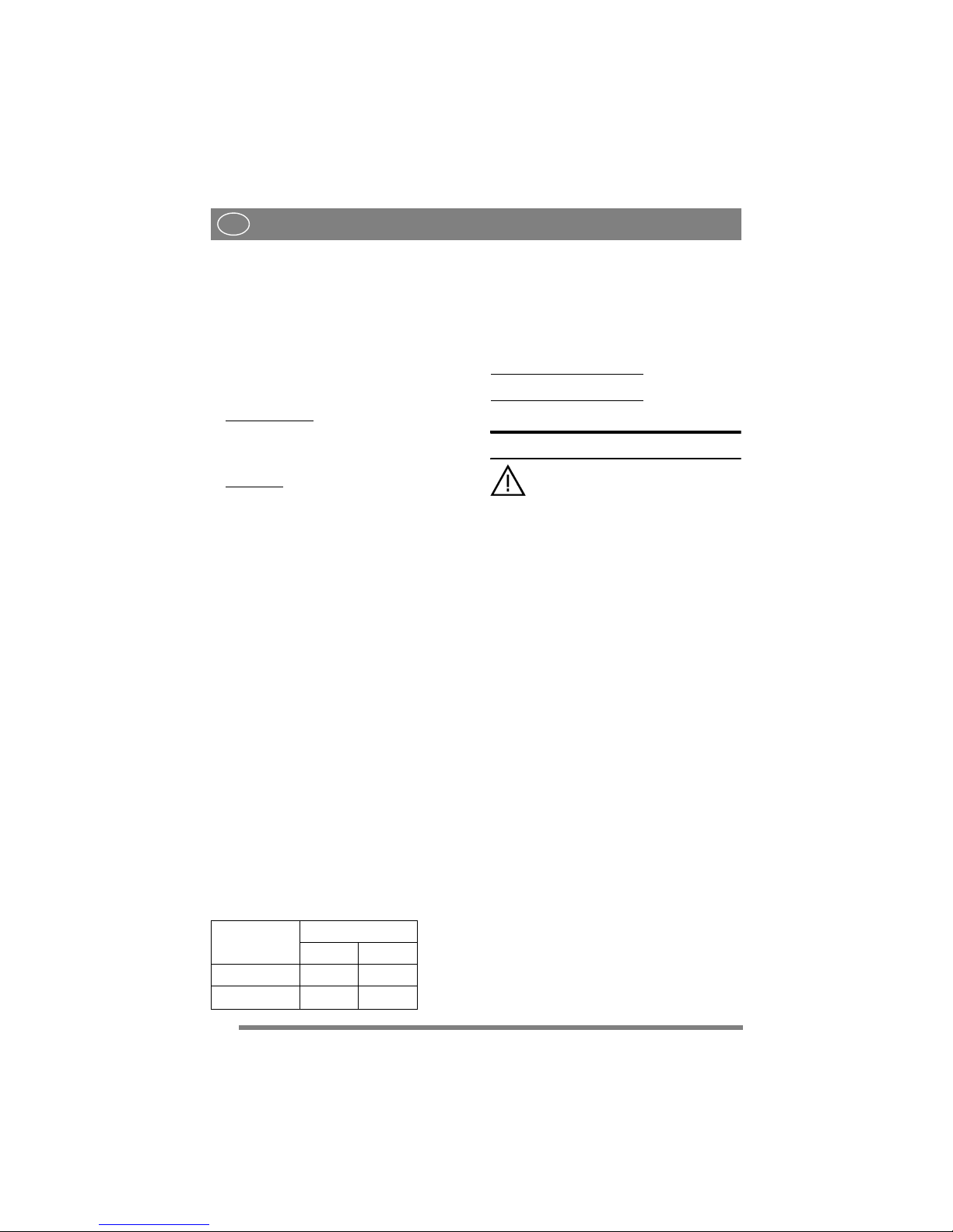
1 ALGEMEEN
Dit symbool geeft een WAARSCHUWING weer. Als de instructies niet nauwkeurig worden opgevolgd, kan dit
leiden tot ernstige persoonlijke verwondingen en/of schade.
Lees de gebruikershandleiding en de
veiligheidsinstructies voor gebruik
goed door.
1.1 Symbolen
Op de machine ziet u de volgende symbolen om u
eraan te herinneren dat voorzichtigheid en oplettendheid bij gebruik geboden is.
Betekenis van de symbolen:
Waarschuwing!
Lees vóór gebruik van de machine de gebruikershandleiding en de veiligheidsvoorschriften.
Waarschuwing!
Zorg dat uw handen of voeten niet onder
de kap komen als de machine loopt.
Waarschuwing!
Kijk uit voor weggegooide voorwerpen.
Houd omstanders op afstand.
Waarschuwing!
Vóór het verrichten van reparaties de
bougiekabel ontkoppelen van de bougie.
1.2 Verwijzingen
1.2.1 Afbeeldingen
De afbeeldingen in deze gebruikershandleiding
zijn genummerd met 1, 2, 3 etc.
Onderdelen in afbeeldingen worden aangegeven
met A, B, C etc.
Een verwijzing naar onderdeel E in afbeelding 5
wordt als volgt weergegeven: “5:E”.
1.2.2 Titels
De titels in deze gebruikershandleiding zijn op de
volgende manier genummerd:
“2.3.2” is een subtitel van “2.3” en wordt onder
deze titel vermeld.
Wanneer naar een titel wordt verwezen, wordt alleen het nummer van deze titel aangegeven. Bijvoorbeeld “Zie 2.3.2”.
2 BESCHRIJVING
2.1 Algemeen
Het maaidek is bedoeld voor gebruik op frontmaaiers van GGP volgens onderstaande tabel.
Het maaidek is leverbaar in één van de volgende
versies:
• Met handmatige instelling van de hoogte.
• Met elektrische instelling van de hoogte.
2.2 Bedieningsmechanismen
2.2.1 Instelling maaihoogte
De maaihoogte kan worden ingesteld tussen 25 en
85 mm.
De instelling kan met een hendel op verschillende
vaste standen worden ingesteld. Zie afb. 2.
2.2.2 Voorwaarts kantelen
Door de twee pinnen een gaatje lager dan de basisinstelling te verplaatsen kan het achterdeel van
het maaidek 12 mm worden opgetild. Zie afb. 2.
2.2.3 Monteren op achterzijde
Het achterdeel van het maaidek wordt geborgd met
de pinnen in afb. 2.
2.2.4 Monteren gereedschapslift
Het maaidek wordt met een ketting en kniphaken
op de gereedschapslift gemonteerd.
Eén kniphaak bepaalt de werkstand en kan in de
kettingschakels worden verplaatst om het hefvermogen in te stellen. Zie afb. 10.
De andere kniphaak wordt gebruikt voor de reinigingsstand.
3 MONTAGE
3.1 Montage 4WD 4000-series and
2000-series
1. Plaats het maaidek vóór de machine.
2. Controleer of de maaidekophangingen als volgt
op de machine zijn gemonteerd.
• Ring (3:D). Alleen machines t/m 2006.
• Maaidekophanging (3:C).
• Ring (3:B).
• Borgring (3:A).
Maaidek 2000 series 4000 series
85 Combi X
95 Combi X X
105 Combi X
Page 14

14
NEDERLANDS
NL
3. Bevestig de armen aan elkaar. Zie afb. 5.
4. Verwijder de riemkap (6:H) door schroefen 6:I
los te draaien.
5. Stel de maximale maaihoogte in.
6. Draai de schroeven van de riemgeleider een
aantal slagen los (21, 22:K) en verwijder de
riem van de maaidekpoelie.
7. Plaats de riem op de machinepoelie en daarna
op de maaidekpoelie.
8. Draai de riemgeleiderschroeven aan (21, 22:K).
9. Span de riem als volgt.
4WD 4000-series
:
Neem de hendel van de riemspanner in uw linkerhand. Trek aan de hendel en vergroot met uw
rechterhand en de riemspanner de spanning op
de buitenkant van de riem. Zie afb. 7.
2000-series
:
Span de riem met de riemspanner. De spanner
moet zich binnen de riem bevinden en naar
links uitsteken (gezien vanuit de positie van de
bestuurder). Zie afb. 9.
10.Monteer de riemkap (6:H) met de schroefen
(6:I).
11.Hang de eenheid op in de gereedschapslift. Zie
afb. 13.
12.Zet het maaidek in de basisstand. Zie 3.4.
3.2 Montage 2WD 4000-series
1. Plaats het maaidek vóór de machine.
2. Controleer of de maaidekophangingen als volgt
op de machine zijn gemonteerd.
• Maaidekophanging (4:G).
• Ring (4:F).
• Borgpen (4:E).
3. Bevestig de armen aan elkaar. Zie afb. 5.
4. Stel de maximale maaihoogte in.
5. Plaats de riem op de riempoelie van de machine.
6. Span de riem als volgt.
Span de riem met de riemspanner. De spanner
moet zich links van de riem bevinden, gezien
vanuit de positie van de bestuurder. Zie afb. 8.
7. Hang de eenheid op in de gereedschapslift. Zie
afb. 10.
8. Zet het maaidek in de basisstand. Zie 3.4.
3.3 Bandenspanning
Kies de bandenspanning aan de hand van onderstaande tabel.
3.4 Basisinstelling
Om optimaal te kunnen maaien, is de juiste basisinstelling noodzakelijk. Het maaidek staat in de
basisinstelling wanneer de achterzijde 5 mm hoger
dan de voorzijde staat. Dit betekent dat het maaidek iets voorover kantelt.
Zet het maaidek in de basisinstelling door deze als
volgt omhoog te bewegen en vast te zetten .
Op machines met wielen van 17”:
Bevestig de
ringen en de pinnen in het bovenste gaatje. Zie afb.
11.
Op machines met wielen van 16”:
Bevestig de
ringen en de pinnen in het middelste gaatje. Zie
afb. 12.
4 MACHINE GEBRUIKEN
Controleer of het gras dat u gaat maaien vrij is van vreemde voorwerpen
zoals stenen etc.
4.1 Maaihoogte
U krijgt de beste maairesultaten als eenderde van
het gras wordt gemaaid. 2/3 van de lengte van het
gras blijft dan staan. Zie afb. 14.
Als het gras lang is en veel korter moet worden,
kunt u beter twee keer maaien met verschillende
maaihoogtes.
Gebruik niet de laagste stand als het oppervlak van
het gazon ongelijkmatig is. Anders loopt u het
gevaar dat de messen beschadigd raken door het
oppervlak en dat de toplaag van het gazon wordt
verwijderd.
4.2 Hellingshoek
Het achterdeel van het maaidek kan worden
opgetild zodat het maaidek een grotere voorwaartse hellingshoek heeft dan bij de basisinstelling. Deze hellingshoek beïnvloedt de
maairesultaten als volgt.
4.2.1 Basisinstelling
Als het maaidek in de basisinstelling staat, wordt
het gras het beste versnipperd en verstrooid. De basisinstelling wordt aanbevolen voor normaal gras.
Zie 3.4.
4.2.2 Grotere hellingshoek
Als het maaidek iets voorovergekanteld is, wordt
het “Multiclip”-effect verminderd terwijl het gemaaide gras beter wordt verstrooid.
Voorover kantelen wordt aanbevolen voor dikker
gras.
Machine Druk (bar/psi)
Voor Achter
4000-series 0,6/9 0,4/6
2000-series
0,4/6 1,2/17
Page 15

15
NEDERLANDS
NL
4.3 Maaiadvies
Volg het onderstaande advies op voor een optimaal
maairesultaat:
• maai regelmatig.
• gebruik de motor op volle kracht.
• het gras moet droog zijn.
• zorg dat de messen scherp zijn.
• houd de onderzijde van het maaidek schoon.
4.4 Composteren/achteruitworp
Het maaidek kan op twee manieren gras maaien:
• Composteren van het gras in het gazon.
• Uitwerpen van het gras achter het maaidek.
Het maaidek is bij aflevering ingesteld op compos-
teren. Om het gras achter het maaidek uit te werpen, moet de plug (afb. 15) worden verwijderd.
Zet het maaidek in de servicestand om de plug te
verwijderen/plaatsen. Zie 5.2/5.3.
5 ONDERHOUD
5.1 Voorbereiding
Service en onderhoud moet altijd worden uitgevoerd aan een stilstaande machine met een uitgeschakelde motor.
Zorg dat de machine niet kan wegrollen. Gebruik daarom altijd de parkeerrem.
Zet de motor af.
Voorkom ongewenst starten door de
bougiekabel van de bougie te ontkoppelen en de contactsleutel te verwijderen.
5.2 Reinigingsstand
1. Schakel de parkeerrem in.
2. Zet de gereedschapslift in de transportstand.
3. Stel de maximale maaihoogte in.
4. Ontkoppel het achterdeel van het maaidek aan
de rechter- en linkerzijde als volgt:
A. Til het linkerachterdeel van het maaidek op
om de belasting op de splitpen te vermind-
eren.
B. Verwijder pinnen en ring. Zie afb. 2.
C. Verwijder de rechtersplitpen en ring op
dezelfde manier.
5. Pak het voorste deel van het maaidek vast en til
het op. Bevestig de ketting zo dat het maaidek
diagonaal naar boven is gericht. Zie afb. 16.
Het is absoluut verboden om de motor
te starten wanneer het maaidek in de
reinigingsstand staat.
Zet het maaidek in de werkstand zoals beschreven
onder “3.1”.
5.3 Service stand, 4WD 4000-series
en 2000-series
1. Schakel de parkeerrem in.
2. Stel de maximale maaihoogte in.
3. Zie afb. 2. Ontkoppel het achterdeel van het
maaidek aan de rechter- en linkerzijde als volgt:
A. Til het linkerachterdeel van het maaidek op
om de belasting op de splitpen te vermind-
eren.
B. Verwijder pinnen en ring.
C. Verwijder de rechtersplitpen en ring op
dezelfde manier.
4. Verwijder de riemkap (6:H) door de schroeven
(6:I) los te draaien.
5. Maak de riem als volgt los.
4WD 4000-series
:
Neem de hendel van riemspanner in uw linkerhand. Trek aan de hendel en verwijder de riemspanner met uw rechterhand. Zie afb. 7
2000-series
:
Verwijder de riemspanner van de riem. Zie afb.
9.
6. Draai de schroeven van de riemgeleider een
aantal slagen los (21, 22:K) en verwijder de
riem van de maaidekpoelie.
7. Haal de riem van de poelie.
8. Laat het maaidek in omgekeerde volgorde zakken nadat u de aanpassingen hebt uitgevoerd.
Zet het maaidek in de werkstand zoals beschreven
onder 3.1.
5.4 Service stand, 2WD 4000-series
1. Schakel de parkeerrem in.
2. Stel de maximale maaihoogte in.
3. Zie afb. 2. Ontkoppel het achterdeel van het
maaidek aan de rechter- en linkerzijde als volgt:
A. Til het linkerachterdeel van het maaidek op
om de belasting op de splitpen te vermind-
eren.
B. Verwijder pinnen en ring.
C. Verwijder de rechtersplitpen en ring op
dezelfde manier.
4. Haal de spanning van de riem door de riemspanner te verwijderen. Zie afb. 9.
5. Haal de riem van de poelie.
6. Pak het voorste deel van het maaidek vast en til
het op. Til het voorste deel op tot het maaidek
volledig verticaal staat en het achterdeel op de
grond rust. Zie afb. 17.
Zet het maaidek in de werkstand zoals beschreven onder “3.1”.
Page 16

16
NEDERLANDS
NL
5.5 Reiniging
Reinig de onderkant van het maaidek na elk gebruik.
Zet het maaidek in de reinigingsstand.
Reinig de onderkant van het maaidek grondig. Ge-
bruik water en een borstel.
Herstel lakbeschadigingen wanneer de opperv-
lakken volledig droog een schoon zijn. Gebruik
duurzame gele verf die geschikt is voor gebruik
buitenshuis en op metaal.
5.6 Messen
5.6.1 Veiligheid
Om de kans op verwondingen bij een botsing te
verminderen en belangrijke onderdelen in het
maaidek te beschermen zijn de volgende noodvoorzieningen aangebracht.
• Bouten tussen messen en mesblad.
• Draaibegrenzing tussen tandwielen en mesas.
• Mogelijkheid tot aflopen van aandrijfriem op de
plastic tandwielen.
5.6.2 Messen vervangen
Draag bij het verwisselen van messen
werkhandschoenen om te voorkomen
dat u zich snijdt.
Controleer altijd of de messen scherp zijn. Dan krijgt u het beste maairesultaat. De messen moeten
jaarlijks worden vervangen.
Controleer de messen altijd als deze ergens tegen
hebben gestoten. Als de messen zijn beschadigd,
moeten de beschadigde onderdelen worden
vervangen.
Gebruik altijd originele reserveonderdelen. Niet-originele reserveonderdelen
kunnen verwondingen veroorzaken,
ook al passen ze in de machine.
De messen zijn vervangbaar. Bij het vervangen
moeten beide messen op hetzelfde messenblad
worden vervangen om onbalans te voorkomen.
Let op!
Let hierop bij het monteren:
• De messen en het mesblad moeten worden
gemonteerd volgens afb. 181.
• De messen kunnen 1/3 slag worden gedraaid in
hun bevestigingen. Plaats de messen onder een
hoek van 90° ten opzichte van elkaar. Zie hieronder bij “5.6.3”.
Aanhaalmoment:
Schroeven (18:P) – 45 Nm
Bouten (18:Q) – 9,8 Nm
Bij een botsing kunnen de bouten (18:Q) breken en
de messen worden verbogen. Mocht dit gebeuren,
plaats dan originele bouten en bevestig ze zoals hierboven is beschreven.
5.6.3 Synchroniseren, messen
Het maaidek heeft gesynchroniseerde messen.
Als één van de messen op een hard voorwerp (bijv.
een steen) stoot, kan de synchronisatie veranderen.
Hierdoor bestaat het risico dat de messen met
elkaar in aanraking komen.
Messen zijn goed gesynchroniseerd als ze onder
een hoek van 90° ten opzichte van elkaar staan. Zie
afb. 19.
Controleer de synchronisatie altijd na een botsing.
Als de messen niet gesynchroniseerd zijn, kunnen
de volgende problemen zijn opgetreden in het
maaidek:
• De aandrijfriem kan van de tandwielen zijn
gelopen.
• De draaibegrenzing tussen tandwielen en mesas
kan in werking zijn getreden. De pijlen in afb.
20 moeten tegenover elkaar liggen bij een intact
maaidek. Als de draaibegrenzing in werking is
getreden, liggen de pijlen niet tegenover elkaar.
• Het mes is niet goed gemonteerd op de mesas.
Kan in drie verschillende standen worden
gemonteerd. Zie 18:R.
Neem bij een onjuiste synchronisatie door de twee
eerstgenoemde problemen contact op met een
geautoriseerde GGP-werkplaats voor reparatie.
6 RESERVEONDERDELEN
Originele GGP-onderdelen en accessoires zijn
speciaal ontworpen voor GGP-machines. "Nietoriginele" onderdelen en accessoires zijn niet gecontroleerd of goedgekeurd door GGP:
Het gebruik van dergelijke onderdelen
kan de werking en veiligheid van de
machine aantasten. GGP is niet verantwoordelijk voor schade of verwondingen die door dergelijke producten zijn
veroorzaakt.
7 ONTWERPREGISTRATIE
Dit product of onderdelen van dit product valt/
valEG 000503107
GGP behoudt zich het recht voor zonder voorafgaande aankondiging wijzigingen in het product
aan te brengen.
Page 17

17
ČEŠTINA
CS
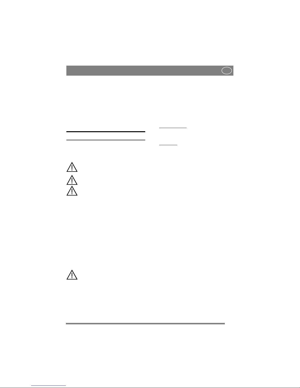
1 OBECNĚ
Tento symbol znamená VÝSTRAHU.
Nedodržení pokynů může vést k
vážnému zranění osob nebo k
poškození majetku.
Musíte si pozorně přečíst tento návod k
použití a bezpečnostní pokyny pro
práci se strojem.
1.1 Symboly
Na stroji jsou umístěny následující symboly.
Informují vás, kdy je při jeho používání třeba dbát
zvýšené opatrnosti.
Symboly mají následující význam:
Výstraha!
Před použitím zařízení si přečtěte návod k
obsluze a bezpečnostní pokyny.
Výstraha!
Je-li zařízení v chodu, nevkládejte pod
jeho kryt ruce ani nohy.
Výstraha!
Dávejte pozor na odhozené předměty.
Pracujte v dostatečné vzdálenosti od
přihlížejících lidí.
Výstraha!
Než začnete zařízení opravovat, odpojte
kabel od zapalovací svíčky.
1.2 Odkazy
1.2.1 Obrázky
Obrázky v tomto návodu k použití jsou číslovány
1, 2, 3 atd.
Součásti zobrazené na obrázcích jsou označovány
A, B, C atd.
Odkaz na součást E na obrázku 5 je uveden jako
„5:E“.
1.2.2 Nadpisy
Nadpisy v tomto návodu k použití jsou číslovány
podle následujícího příkladu:
„2.3.2“ je dílčí nadpis pod „2.3“ a je uveden pod
tímto nadpisem.
Při odkazování na nadpisy se normálně uvádí
pouze číslo nadpisu, např. „Viz 2.3.2“.
2 POPIS
2.1 Obecně
Sekací plošina je určena k použití na strojích GGP
s předním agregátem
Řezací plošina se dodává v jedné z následujících
verzí:
•S ručním nastavováním výšky sekání.
• S elektrickým nastavováním výšky sekání.
2.2 Ovládací prvky
2.2.1 Nastavení výšky sekání
Výšku sekání lze nastavit mezi 25 a 85 mm.
Nastavení lze měnit na řadu pevně daných poloh
pomocí páky. Viz obr. 2.
2.2.2 Naklonění dopředu
Zadní část sekací plošiny lze zvednout o 12 mm
přemístěním dvou kolíků o jeden otvor dolů od
základního nastavení. Viz obr. 2.
2.2.3 Zadní montáž
Zadní část sekací plošiny je připevněna kolíky
znázorněnými na obr. 2.
2.2.4 Montáž do nástrojového zvedáku
Plošina se instaluje do nástrojového zvedáku
pomocí řetězu a karabin.
Jedna karabina je určena pro pracovní polohu a lze
ji posunovat po článcích řetězu za účelem
nastavení zvedací síly. Viz obr. 10.
Druhá karabina je určena pro polohu pro čištění.
3 MONTÁŽ
3.1 Montáž 4WD
1. Umístěte plošinu před stroj.
2. Zkontrolujte, zda jsou na svém místě tyto
montážní body.
• Podložka (3:D). Pouze modely z roku 2006
a starší.
• Držák plošiny (3:C).
• Podložka (3:B).
• Pojistný kroužek (3:A).
3. Na obě strany našroubujte ramena. Viz obr. 5.
4. Povolte šroub (6:I) a odstraňte ochranný kryt
řemene (6:H).
Sekací plošina XK 13 XK 16
95 Combi X X
105 Combi X
Page 18

18
ČEŠTINA
CS
5. Nastavte maximální výšku sekání.
6. Šrouby vodicí vidlice (21, 22:K) povolte o
několik otáček. Klínový řemen stáhněte z
řemenice plošiny.
7. Řemen nasaďte na řemenici stroje a poté na
řemenici sekací plošiny.
8. Utáhněte šrouby vodicí vidlice (21, 22:K).
9. Řemen nainstalujte podle následujícího
postupu.
Levou rukou uchopte páku napínáku řemene.
Zatáhněte za páku a pravou rukou přiložte
napínák na vnější stranu řemene. Viz obr. 9.
10.Šroubem (6:I) upevněte ochranný kryt řemene
(6:H).
11.Zavěste zařízení do nástrojového zvedáku. Viz
obr. 10.
13.Proveďte základní nastavení sekací plošiny. Viz
obr. 3.4.
3.2 Montáž 2WD
1. Umístěte plošinu před stroj.
2. Zkontrolujte, zda jsou na svém místě tyto
montážní body.
• Držák plošiny (4:G).
• Podložka (4:F).
• Pojistný čep (4:E).
3. Na obě strany našroubujte ramena. Viz obr. 5.
4. Nastavte maximální výšku sekání.
5. Nasaďte řemen na řemenici stroje a sekací
plošiny.
6. Řemen nainstalujte podle následujícího
postupu.
Řemen napněte napínací řemenicí. Napínací
řemenice musí být na levé straně klínového
řemene (z pohledu obsluhy). Viz obr. 8.
7. Zavěste zařízení do nástrojového zvedáku. Viz
obr. 9.
8. Proveďte základní nastavení sekací plošiny. Viz
obr. 3.4.
3.3 Tlak v pneumatikách
Tlak v pneumatikách zvolte podle následující
tabulky.
3.4 Základní nastavení
Aby sekací plošina optimálně sekala, vyžaduje se
správné základní nastavení. Plošina je v základním
nastavení tehdy, když je zadní okraj 5 mm nad
předním okrajem. To znamená, že plošina je
nakloněna dopředu.
Podle typu stroje nastavte sekací plošinu do
základní polohy.
Na strojích se 17” koly:
Do horního otvoru
nainstalujte podložky a kolíky. Viz obr. 11.
Na strojích se 16” koly:
Do středního otvoru
nainstalujte podložky a kolíky. Viz obr. 12.
4 POUŽITÍ STROJE
Zkontrolujte, zda tráva, která se má
sekat, neobsahuje žádné cizorodé
předměty, např. kameny atd.
4.1 Výška sekání
Nejlepších výsledků se dosáhne tehdy, když se
seká horní třetina trávy, tzn. 2/3 trávy zůstanou na
místě. Viz obr. 14.
Pokud je tráva dlouhá a je ji třeba podstatně zkrátit,
sekejte dvakrát s různými výškami sekání.
Pokud je povrch trávníku nerovný, nepoužívejte
nejnižší výšky sekání. To by mohlo vést k riziku
poškození nožů o povrch a odstranění vrchní půdní
vrstvy trávníku.
4.2 Náklon
Zadní část sekací plošiny lze zvednout tak, aby
byla plošina nakloněna dopředu více než při
základním nastavení. Tento náklon ovlivní
výsledky sekání.
4.2.1 Základní nastavení
Když je plošina v základním nastavení, dosahuje
se nejlepšího mulčovacího efektu a useknutá tráva
se dobře rozptyluje. Pro normální trávu se
doporučuje základní nastavení.
4.2.2 Větší sklon
Když je sekací plošina nakloněna dopředu, snižuje
se “Multiclip”-efekt, zatímco se useknutá tráva
lépe rozptyluje.
Naklonění dopředu se doporučuje pro silnější
trávu.
4.3 Rady pro sekání
Abyste dosáhli optimálních výsledků sekání, řiďte
se následujícími radami:
• Sekejte často.
• Udržujte motor v maximálních otáčkách.
• Tráva by měla být suchá.
• Používejte ostré nože.
• Spodní stranu sekací plošiny udržujte v čistém
stavu.
Model Tlak (bar/psi)
Přední Zadní
XK 0,6/9 0,4/6
Page 19

19
ČEŠTINA
CS
4.4 Mulčování/zadní vyhazování
Plošina může sekat trávu dvěma způsoby:
•Mulčovat – posekaná tráva se rozptýlí do
trávníku.
• Vyhazovat za plošinu.
Plošina je při dodání nastavena na mulčování.
Chcete-li vyhazovat trávu za plošinu, musí se
odstranit kolík na obr. 15.
Chcete-li odstranit/nainstalovat kolík, uveďte
plošinu do čistící nebo servisní polohy.
5 ÚDRŽBA
5.1 Příprava
Veškerý servis a údržba se musí provádět na
stojícím stroji s vypnutým motorem.
Proti pohybu stroj vždy zajistěte
parkovací brzdou.
Vy pn ěte motor.
Abyste předešli neúmyslnému spuštění
motoru, odpojte kabel od zapalovací
svíčky a vytáhněte klíček ze zapalování.
5.2 Poloha pro čištění
1. Aktivujte parkovací brzdu.
2. Nastavte nástrojový zvedák do přepravní
polohy.
3. Nastavte nejvyšší výšku sekání.
4. Podle následujícího postupu demontujte na
pravé i levé straně zadní část sekací plošiny:
A. Přizdvihněte pravou zadní stranu plošiny,
abyste uvolnili kolík.
B. Odstraňte kolíky a podložku. Viz obr. 2.
C. Stejným způsobem odstraňte levý kolík s
podložkou.
5. Uchopte přední okraj plošiny a zvedněte ho.
Zavěste řetěz tak, aby plošina mířila úhlopříčně
nahoru. Viz obr. 16.
Je přísně zakázáno spouštět motor,
když je plošina v poloze pro čištění.
6. Proveďte opravná opatření a opačným
postupem spusťte plošinu k zemi. Podle
postupu v oddíle “3.1” vraťte sekací plošinu na
své místo.
5.3 Servisní poloha, 4WD
1. Aktivujte parkovací brzdu.
2. Nastavte maximální výšku sekání.
3. Viz obr. 2. Podle následujícího postupu
demontujte na pravé i levé straně zadní část
sekací plošiny:
A. Přizdvihněte pravou zadní stranu plošiny,
abyste uvolnili kolík.
B. Odstraňte kolíky a podložku.
C. Stejným způsobem odstraňte levý kolík s
podložkou.
4. Povolte šroub (6:I) a odstraňte ochranný kryt
řemene (6:H).
5. Podle následujícího postupu povolte řemen.
Levou rukou uchopte páku napínáku řemene.
Zatáhněte za páku a pravou rukou odstraňte
napínák. Viz obr. 7.
6. Šrouby vodicí vidlice (21, 22:K) povolte o
několik otáček. Klínový řemen stáhněte z
řemenice plošiny.
7. Stáhněte klínový řemen z řemenice plošiny.
8. Uchopte přední okraj plošiny a zvedněte jej.
Zvedněte plošinu do zcela svislé polohy tak,
aby se zadní stranou opírala o zem. Viz obr. 17.
Podle postupu v oddíle 3.1 vraťte sekací plošinu na
své místo.
5.4 Servisní poloha, 2WD
1. Aktivujte parkovací brzdu.
2. Nastavte maximální výšku sekání.
3. Viz obr. 2. Podle následujícího postupu
demontujte na pravé i levé straně zadní část
sekací plošiny:
A. Přizdvihněte pravou zadní stranu plošiny,
abyste uvolnili kolík.
B. Odstraňte kolíky a podložku.
C. Stejným způsobem odstraňte levý kolík s
podložkou.
4. Odstraněním napínáku povolte řemen. Viz obr.
9.
5. Stáhněte klínový řemen z řemenice stroje.
6. Uchopte přední okraj plošiny a zvedněte jej.
Zvedněte plošinu do zcela svislé polohy tak,
aby se zadní stranou opírala o zem. Viz obr. 17.
Podle postupu v oddíle 3.2 vraťte sekací plošinu na
své místo.
5.5 Čištění
Spodní strana plošiny se musí po každém použití
vyčistit.
Nastavte plošinu do polohy pro čištění.
Pečlivě vyčistěte spodní stranu plošiny. Stroj
čistěte vodou a kartáčem.
Až bude povrch úplně suchý a čistý, opravte
poškozený lak. Použijte trvanlivou žlutou barvu na
kovy ve venkovním prostředí.
Page 20

20
ČEŠTINA
CS
5.6 Nože
5.6.1 Bezpečnost
V zájmu snížení nebezpečí úrazu v případě střetu
se strojem a ochrany důležitých součástí sekací
plošiny je stroj vybaven těmito bezpečnostními
prvky:
• bezpečnostní šrouby mezi noži a nožovou
lištou,
• omezovač kroutícího momentu mezi
převodovkou a nožovou hřídelí,
• možnost proklouznutí hnacího řemene na
plastovém převodovém soukolí.
5.6.2 Výměna nožů
Při výměně nože (nožů) používejte
ochranné rukavice, abyste se nezranili.
Pravidelně kontrolujte, zda jsou nože ostré. To je
pro kvalitní posekání nezbytné. Nože měňte
jednou za rok.
Po každém střetu s cizím předmětem nože
zkontrolujte. Jestliže dojde k poškození systému
nožů, poškozené díly vyměňte.
Vždy používejte originální náhradní
díly. Jiné než originální náhradní díly
mohou způsobit zranění, i když se ke
stroji hodí.
Nože jsou výměnné. Při výměně se musí vyměnit
oba nože na stejné nožové liště, aby byla lišta
vyvážená.
Pozor!
Při zpětné montáži zkontrolujte následující:
• Nože a nožová lišta musí být nainstalovány
podle obr. 18.
• Nože lze v montážních bodech otočit o 120 °.
Upevněte je tak, aby navzájem svíraly
úhel 90 °. Viz níže „5.5.3“.
Utahovací moment:
Šrouby (21:P) - 45 Nm
Bezpečnostní šrouby (21:Q) - 9,8 Nm
V případě nárazu se mohou bezpečnostní šrouby
(18:Q) zlomit a nože se mohou ohnout dozadu. V
takovém případě nainstalujte originální
bezpečnostní šrouby a utáhněte je podle výše
popsaného postupu.
5.6.3 Synchronizace, nože
Nože sekací plošiny jsou synchronizované.
Pokud jeden z nožů narazí na pevný předmět (např.
kámen), může se jejich synchronizace narušit. V
takovém případě hrozí nebezpečí vzájemné kolize
nožů.
Správně synchronizované nože musí svírat
úhel 90 °. Viz obr. 19.
Po nárazu vždy zkontrolujte synchronizaci.
Pokud nože nejsou synchronizovány, může to být
způsobenou některou z následujících závad sekací
plošiny:
• Řemen přímého pohonu proklouzl na
převodovém soukolí.
• Omezovač kroutícího momentu mezi
převodovkou a nožovou hřídelí se pootočil. Jeli sekací plošina správně nastavena, šipky (viz
obr. 20) musí být přesně proti sobě. Pootočí-li
se omezovač kroutícího momentu, šipky
nejsou proti sobě.
•Nůž je na hřídeli nesprávně nainstalován. Lze
jej nainstalovat ve třech různých polohách. Viz
obr. 18:R.
Je-li synchronizace narušena z prvního nebo
druhého důvodu, nechte sekací plošinu opravit v
autorizované servisní dílně GGP.
6 NÁHRADNÍ DÍLY
Originální náhradní díly a příslušenství
společnosti GGP jsou speciálně určeny pro stroje
GGP. Vezměte, prosím, na vědomí, že
„neoriginální“ náhradní díly a příslušenství nebyly
zkontrolovány nebo schváleny společností GGP:
Použití takových dílů a příslušenství
může negativně ovlivnit funkce a
bezpečnost stroje. Společnost GGP
nepřijímá žádnou odpovědnost za
škody nebo zranění způsobené
takovými výrobky.
7 REGISTRACE KONSTRUKCE
Tento výrobek nebo jeho díly jsou chráněny
následujícími registracemi konstrukce:
EG 000503107
Společnost GGP si vyhrazuje právo provádět
změny produktu bez předchozího upozornění.
Page 21

Manufactured by GGP Sweden AB
 Loading...