

Page 1
Operating Manual
IP251
Universal SSI / RS232 signal converter for operation with absolute SSI sensors and encoders
Product Features:
Converts SSI data as well as serial data to parallel binary, Gray oder BCD data format
Linearization facilities by freely programmable in-/output curves
Additional facilities like bit-blanking, round-loop-operation etc.
Parallel output 25 bits (push-pull, short circuit proof)
RS232 interface for serial readout of the sensor data
SSI: Master or Slave operation
18 to 30 VDC power supply
motrona GmbH, Zeppelinstraße 16, DE - 78244 Gottmadingen, Tel. +49 (0) 7731 9332-0, Fax +49 (0) 7731 9332-30, info@motrona.com, www.motrona.com
Page 2

Version:
Description:
IP25101a/ HK/AF/ Apr-03
Original Version
IP25101b/ AF/HK/ Aug.03
Correction DIL-switch position 7 ON/OFF. “Parallel Mode” 3,4,5 and “Parallel
Value” for direct serial access to the parallel output
IP25101c/ PP/Nov. 12
Added chapter 7.5
IP25102a/ kk/nw/Sept. 13
Added Printermode
Ip251_02b_oi/Dez-15/ag
„RS485“ removed from parameter table. Legal Notices added. New design
and chapter for “Safety Instructions“. “Technical specifications” actualized.
Smaller corrections and modulations
Legal notices:
All contents included in this manual are protected by the terms of use and copyrights of motrona GmbH. Any
reproduction, modification, usage or publication in other electronic and printed media as well as in the internet
requires prior written authorization by motrona GmbH.
Ip251_02b_oi_e.doc / Apr-16 Page 2 / 28
Page 3

Table of Contents
1. Safety Instructions and Responsibility ........................................................ 4
1.1. General Safety Instructions ................................................................................... 4
1.2. Use according to the intended purpose ................................................................ 4
1.3. Installation ............................................................................................................. 5
1.4. Cleaning, Maintenance and Service Notes ........................................................... 5
2. Introduction ................................................................................................ 6
2.1. Applicable encoders and sensors: ........................................................................ 6
2.2. Remark about the encoder resolution: .................................................................. 6
3. Terminal Assignment .................................................................................. 6
4. Connections ................................................................................................ 7
4.1. SSI encoder, Master operation ............................................................................. 7
4.2. SSI encoder, Slave operation ................................................................................ 7
4.3. Hold input .............................................................................................................. 7
4.4. Parallel outputs ..................................................................................................... 8
4.5. “Data stable” output ............................................................................................. 8
4.6. Serial interface ...................................................................................................... 9
5. DIL Switch Settings .................................................................................. 10
6. Extended Functions with PC Setup ............................................................ 11
6.1. Self-Test .............................................................................................................. 12
6.2. Output value ........................................................................................................ 12
6.3. Hold key ............................................................................................................... 12
7. Parameters ............................................................................................... 13
7.1. Scaling of serial readout data ............................................................................. 13
7.2. Scaling of parallel output data ............................................................................ 13
7.3. Ring counter, parameter “Round Loop”: ............................................................. 15
7.4. More parameters: ................................................................................................ 17
7.5. Parameters for RS232 settings ........................................................................... 22
8. Test Functions ........................................................................................... 25
9. Technical Specifications ........................................................................... 26
10. Dimensions ............................................................................................... 27
11. Parameter List, Default Settings ............................................................... 28
Ip251_02b_oi_e.doc / Apr-16 Page 3 / 28
Page 4

1. Safety Instructions and Responsibility
1.1. General Safety Instructions
This operation manual is a significant component of the unit and includes important rules and
hints about the installation, function and usage. Non-observance can result in damage and/or
impairment of the functions to the unit or the machine or even in injury to persons using the
equipment!
Please read the following instructions carefully before operating the device and observe all
safety and warning instructions! Keep the manual for later use.
A pertinent qualification of the respective staff is a fundamental requirement in order to use
these manual. The unit must be installed, connected and put into operation by a qualified
electrician.
Liability exclusion: The manufacturer is not liable for personal injury and/or damage to property
and for consequential damage, due to incorrect handling, installation and operation. Further
claims, due to errors in the operation manual as well as misinterpretations are excluded from
liability.
In addition the manufacturer reserve the right to modify the hardware, software or operation
manual at any time and without prior notice. Therefore, there might be minor differences
between the unit and the descriptions in operation manual.
The raiser respectively positioner is exclusively responsible for the safety of the system and
equipment where the unit will be integrated.
During installation or maintenance all general and also all country- and application-specific
safety rules and standards must be observed.
If the device is used in processes, where a failure or faulty operation could damage the system
or injure persons, appropriate precautions to avoid such consequences must be taken.
1.2. Use according to the intended purpose
The unit is intended exclusively for use in industrial machines, constructions and systems. Nonconforming usage does not correspond to the provisions and lies within the sole responsibility
of the user. The manufacturer is not liable for damages which has arisen through unsuitable
and improper use.
Please note that device may only be installed in proper form and used in a technically perfect
condition - in accordance to the Technical Specifications (see chapter 9). The device is not
suitable for operation in explosion-proof areas or areas which are excluded by the EN 61010-1
standard.
Ip251_02b_oi_e.doc / Apr-16 Page 4 / 28
Page 5

1.3. Installation
The device is only allowed to be installed and operated within the permissible temperature
range. Please ensure an adequate ventilation and avoid all direct contact between the device
and hot or aggressive gases and liquids.
Before installation or maintenance, the unit must be disconnected from all voltage-sources.
Further it must be ensured that no danger can arise by touching the disconnected voltagesources.
Devices which are supplied by AC-voltages, must be connected exclusively by switches,
respectively circuit-breakers with the low voltage network. The switch or circuit-breaker must
be placed as near as possible to the device and further indicated as separator.
Incoming as well as outgoing wires and wires for extra low voltages (ELV) must be separated
from dangerous electrical cables (SELV circuits) by using a double resp. increased isolation.
All selected wires and isolations must be conform to the provided voltage- and temperatureranges. Further all country- and application-specific standards, which are relevant for structure,
form and quality of the wires, must be ensured. Indications about the permissible wire crosssections for wiring are described in the Technical Specifications (see chapter 9).
Before first start-up it must be ensured that all connections and wires are firmly seated and
secured in the screw terminals. All (inclusively unused) terminals must be fastened by turning
the relevant screws clockwise up to the stop.
Overvoltages at the connections must be limited to values in accordance to the overvoltage
category II.
For placement, wiring, environmental conditions as well as shielding and earthing/grounding of
the supply lines the general standards of industrial automation industry and the specific
shielding instructions of the manufacturer are valid. Please find all respective hints and rules on
www.motrona.com/download.html --> “[General EMC Rules for Wiring, Screening and
Earthing]”.
1.4. Cleaning, Maintenance and Service Notes
To clean the front of the unit please use only a slightly damp (not wet!), soft cloth. For the rear
no cleaning is necessary. For an unscheduled, individual cleaning of the rear the maintenance
staff or assembler is self-responsible.
During normal operation no maintenance is necessary. In case of unexpected problems, failures
or malfunctions the device must be shipped for back to the manufacturer for checking,
adjustment and reparation (if necessary). Unauthorized opening and repairing can have
negative effects or failures to the protection-measures of the unit.
Ip251_02b_oi_e.doc / Apr-16 Page 5 / 28
Page 6

2. Introduction
1
2
3
4
5
6
7
8
9
1
0
1
1
1
2
COM + (+5....+27V max)
SSI- Clock (-)
SSI- Clock (+)
GND ( - )
+18...30 VDC (typ. 200 mA)
NC
SSI Data (-)
SSI Data (+)
Hold
GND ( - )
P
O
W
E
R
NC
NC
IP251 represents a small and low-cost, but highly performing converter for industrial
applications, where the information of a sensor or encoder with SSI interface needs to be
converted to a parallel signal or a serial RS232 data format. Also it is possible to convert serial
RS232 data to a parallel format.
The unit has been designed as a compact module with 12 screw terminals, a 9-position and a
25-position SUB-D connector (female). The housing is suitable for simple and quick snap-on
mounting on a top hat rail (according to the EN 60715 standard).
2.1. Applicable encoders and sensors:
Single-turn or multi-turn absolute encoders and all similar sensors using a standard SSI
interface (6 to 25 bits of resolution with binary or Gray code). The unit can operate in either
Master mode (clock signal generated by the IP251 unit), or in
Slave mode (clock signal generated by a remote device)
2.2. Remark about the encoder resolution:
The unit provides settings for the standard resolutions of 13 bits, 21 bits and 25 bits. In general,
for sensors with other resolutions you can use the next higher setting (i.e. set the unit to 21 bits
with a sensor of 16 bits).
Depending on brand and specification of the encoder, in some cases it may be necessary to
blank out the surplus bits by using the bit blanking function described later. In general however,
the unit should work perfectly also without special bit blanking.
3. Terminal Assignment
The subsequent diagram shows the assignment of the screw terminals. GND terminals 4 and 6
are connected internally. Depending on input voltage and load of the auxiliary voltage output,
the total power consumption of the unit is about 200 mA.
Ip251_02b_oi_e.doc / Apr-16 Page 6 / 28
We recommend to connect the Minus wire of the power supply to earth potential.
Page 7
4. Connections
2
3
8
9
4 (GND)
Clock-
Clock+
GND
Data-
Data+
SSI encoder
IP251 converter
Master mode
2
3
8
9
4 (GND)
IP251 converter
Slave mode
+ -
C
l
o
c
k
+
C
l
o
c
k
-
D
a
t
a
+
D
a
t
a
-
Encoder
Master
ClockClock+
DataData+
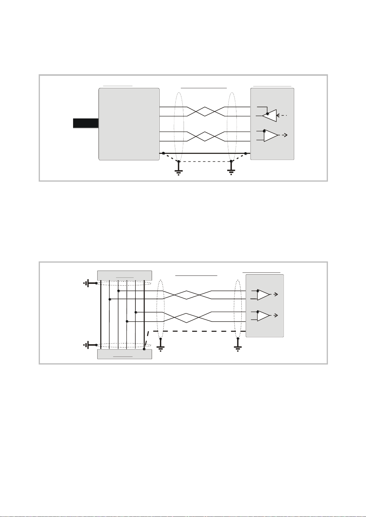
4.1. SSI encoder, Master operation
We recommend to connect the screen to GND and earth potential on both sites.
4.2. SSI encoder, Slave operation
With this mode, the IP251 converter operates in parallel to another unit, acting as a „listener“
to the existing data communication. Quite according to need, the common potential of the
master can be connected to terminal 4 (GND), or remain open for fully differential operation.
4.3. Hold input
A HIGH signal to this input freezes the parallel output data.
The Hold function becomes active 500 µs after the rising edge of the signal and remains active
for the duration of the signal. With PC setup, the polarity of the signal can be inverted (Falling
edge, active low, see register “Hold polarity”).
The Hold input provides PNP/HTL characteristics (LOW = open or 0 … 3 V, HIGH =10 … 30 V)
Ip251_02b_oi_e.doc / Apr-16 Page 7 / 28
Page 8
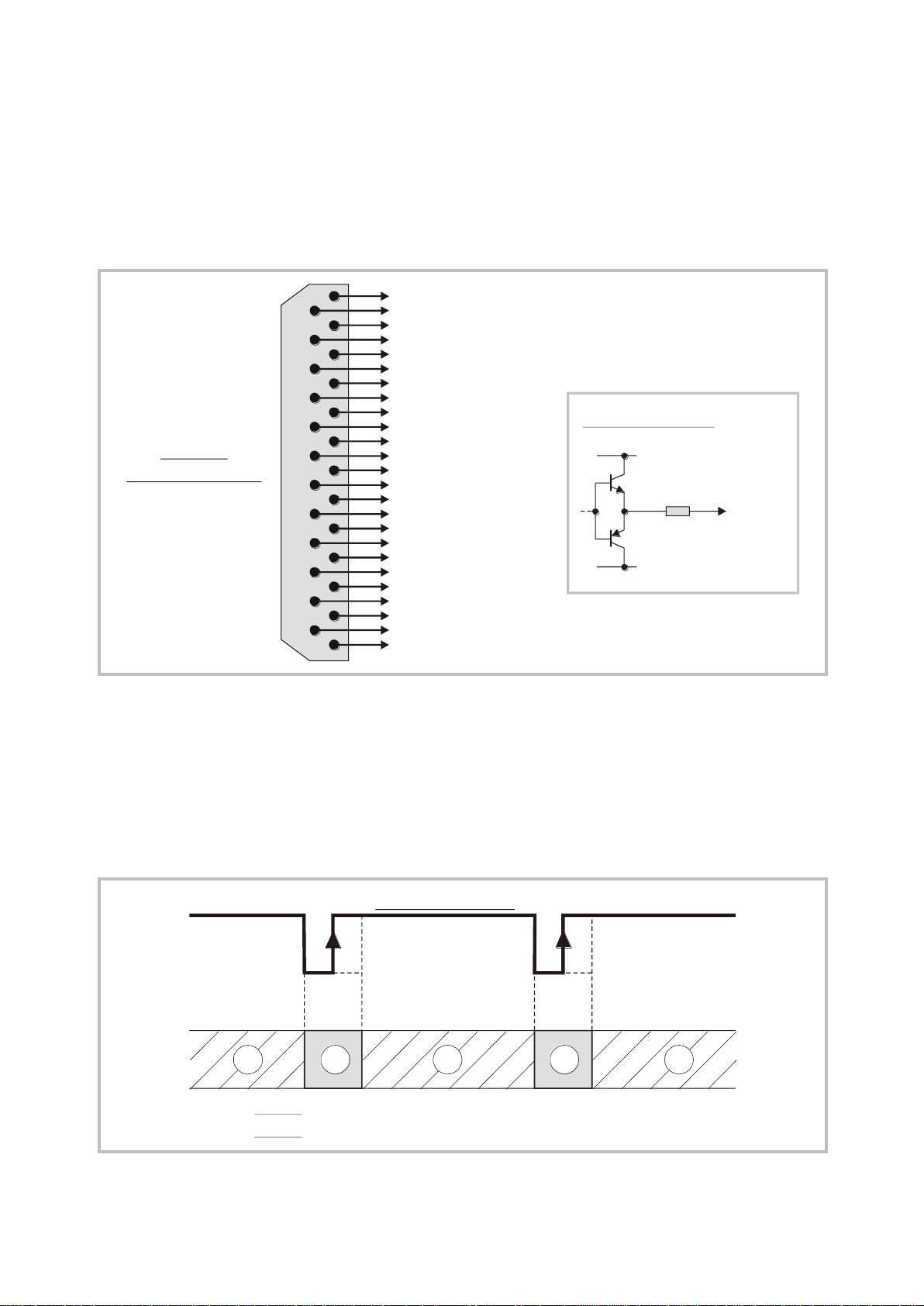
4.4. Parallel outputs
Bit13
Bit 25
Bit 12
Bit 24
Bit 11
Bit 23
Bit 10
Bit 22
Bit 9
Bit 21
Bit 8
Bit 20
Bit 7
Bit 19
Bit 6
Bit 18
Bit 5
Bit 17
Bit 4
Bit 16
Bit 3
Bit 15
Bit 2
Bit 14
Bit 1
R = 600 Ohms
GND
COM +
OUT
Typical output circuit:
SUB-D-25
(female on unit site)
13
25
12
24
11
23
10
22
9
21
8
20
7
19
6
18
5
17
4
16
3
15
2
14
1
12121
Data stable signal
Zone 1: Parallel output data subject to change
Parallel output data are stable
Zone 2:
The unit provides 25 push-pull outputs which are short-circuit proof. The separate common
output voltage for the outputs must be applied to screw terminal 1 (COM+). The maximum
voltage to COM+ should not exceed +27 V, otherwise no continuous short-circuit proof of
the outputs can be guaranteed.
The voltage drop between COM+ and an output in HIGH state is approx. 1 V (unloaded).
4.5. “Data stable” output
The output for bit 25 can be configured as a “Data-stable” signal by means of the DIL-switch.
In this case a LOW state indicates that parallel output data are stable and will not change. The
rising edge of the signal still guarantees stable data and can be used for remote Latch of the
parallel data.
The LOW duration of the signal is at least 1/3 of the SSI Wait Time setting.
Ip251_02b_oi_e.doc / Apr-16 Page 8 / 28
Page 9

4.6. Serial interface
5
4
3
2
1
9
8
7
6
GND int.
TxD
RxD
RS232
SUB-D-9-connector
( on unit site)female
GND
1
2
3
4
5
9
8
7
6
1
2
3
4
5
9
8
7
6
TxD
RxD
PC connection cable(female) (male)
IP251PC
For PC setup and for serial readout of the encoder position, a serial RS232 interface is available.
The serial interface allows to operate and setup the unit as well as readout the encoder position
by a PC or Notebook.
Ip251_02b_oi_e.doc / Apr-16 Page 9 / 28
Page 10

5. DIL Switch Settings
Changes of switch settings will become active only
after the next power-up cycle!
SSI Resolution:
3 OFF, 4 OFF : not valid
3 ON, 4 OFF : 25 bit encoder
3 OFF, 4 ON : 21 bit encoder
3 ON, 4 ON : 13 bit encoder
Set Default:
OFF: Unit loads default settings with every power-up cycle
ON : No loading of default settings upon power-up.
Update Mode
ON: Update of parallel output in a fixed preset time pattern
OFF: Update of parallel output after every SSI telegram
Pin 25 Function:
OFF: Pin 25 indicates that output data is stable (LOW)
ON : Pin 25 is a normal data output (bit 25 or error bit)
SSI Code
OFF: Gray Code
ON: Binary Code
SSI Mode:
OFF : Slave Operation
ON : Master Operation
Pin 25 Function:
OFF : Pin 25 = Error bit output
ON : Pin 25 = normal data output (bit 25)
1 2 3 4 5 6 7 8
The DIL switch located on the top site of the unit provides encoder settings and customerspecific settings of the desired operation modes.
The switch settings shown in the example are suitable for Master operation of a 25 bit SSI
encoder with Gray coded output. The parallel output operates with equidistant update times
and pin 25 is used to indicate valid and stable output data.
Ip251_02b_oi_e.doc / Apr-16 Page 10 / 28
Page 11

6. Extended Functions with PC Setup
Ex factory, all motrona units use the following serial standard settings:
Unit No. 11, Baud rate 9600, 1 start/ 7 data/ parity even/ 1 stop bit
If the serial settings of the unit should be unknown, you can run the
„SCAN“ function from the „TOOLS“ menu to find out.
For normal use with standard applications, the unit is ready to work after correct wiring and
setting of the DIL switches. In this case, the subsequent sections are not relevant.
With use of a PC however, you have full access to useful complementary functions and tests as
shown subsequently. For this you will need the PC operator software OS3.x which is available
for free download from
Connect your PC to the converter, using a serial RS232 cable like shown in section 4.6. of this
manual. Then run the OS3.x software and you will see the following screen:
www.motrona.com
In case your text and color fields remain empty and the headline says „OFFLINE“, you must
verify your serial settings. To do this, select „Comms“ from the menu bar.
Ip251_02b_oi_e.doc / Apr-16 Page 11 / 28
Page 12

6.1. Self-Test
On your PC screen, in the ”Outputs” field, you find several indicator boxes.
When the ”Self-test passed” box lights red, this indicates that the unit has correctly initialized
and is ready to work. The fields ”Status SSI-CLK” and ”Status SSI-Data” indicate that the clock
and data lines work correctly (red color = o.k.) *)
You may observe that these boxes blink, because of the update cycle of your PC. However, you
should see “red” predominantly with correct operation of the lines.
6.2. Output value
When the encoder position is changing, this window must show increasing or decreasing
encoder values. Where the color bar or the percentage display are jumping or hunting, please
check once more for correct setting of the DIL switch.
6.3. Hold key
This soft key operates in parallel to the hardware input terminal 10 and allows freezing the
parallel output from the PC screen. Indicator boxes in the RS column indicate that the Hold
function is active, either by software or by hardware command.
*) Testing the clock lines is primarily useful with Slave operation. Though the test works also in Master
mode, the result says only that the internal generation of the clock works fine. However, in Master mode,
this test cannot indicate faulty clock drivers or bad wiring of the clock lines
Ip251_02b_oi_e.doc / Apr-16 Page 12 / 28
Page 13

7. Parameters
Serial Readout = SSI encoder data x [
xOperand
/Operand
] + +/-Operand
Linearisation Mode = 0
Round Loop = 0
Parallel Mode = 0 (binary output)
= 1 (Gray coded output)
= 2 (BCD output)
Parallel Inv. = 0 (Log 1 = „HIGH“, normal output polarity)
= 1 (Log 1 = „LOW“, inverted output polarity)
7.1. Scaling of serial readout data
You can read out the actual SSI position of the encoder at any time from the serial link. For
setting of communication parameters (baud rate etc.) you need a PC.
IP251 uses the DRIVECOM communication standard according to ISO 1745. Details about this
protocol can be found in the file Serpro1a.doc,
(available for Download from www.motrona.com)
The serial access code for the actual encoder position is „ :8 ”
(ASCII characters for colon and 8)
Serial data be re-scaled by using the parameters xOperand, /Operand and +/-Operand :
There operands affect only serial readout of encoder data but not the parallel data output.
With the settings
xOperand = 1.0000,
/Operand = 1.0000
the serial readout value equals to the SSI encoder value.
+/-Operand = 0.0000
7.2. Scaling of parallel output data
7.2.1. If you like to convert the SSI encoder data to the parallel output straight 1:1
The settings of the Linearization registers are not important in this case.
Ip251_02b_oi_e.doc / Apr-16 Page 13 / 28
Page 14

7.2.2. If you like to convert the SSI encoder data to the parallel output with a
Linearisation Mode = 1
Round Loop = 0
Parallel Mode = 0 (binary output)
= 1 (Gray output)
= 2 (BCD output)
Parallel Inv. = 0 (Log 1 = „HIGH“, normal output polarity)
= 1 (Log 1 = „LOW“, inverted output polarity)
Linear In (100%) = 65 536
Linear Out (100%) = 10 000
P1 (x) = 000.0 %
P1 (y) = 000.0 %
P2 (x) = 100.0 %
P2 (y) = 100.0 %
Linearisation Mode = 1
Round Loop = 0
Parallel Mode = 0 (binary output)
= 1 (Gray output)
= 2 (BCD output)
Parallel Inv. = 0 (Log 1 = „HIGH“, normal output polarity)
= 1 (Log 1 = „LOW“, inverted output polarity)
Use registers P1(x) to P16(x) to specify the coordinates on the x-axis. These are the
original SSI data generated by the sensor. These settings are in % of full scale
Now enter the attached values to registers P1(y) to P16(y). These are the values
that the parallel output will generate instead of the x- values *)
*) Example:. P2(y) will substitute P2(x) etc.
different scaling:
Example: encoder 16 Bit = 65536 steps to be converted to a range of 0 - 10 000
on the parallel output
7.2.3. If you like to transform the SSI encoder data to a curve on the
parallel output site (Linearization)
Example: encoder 16 Bit = 65536 steps to be transformed to a programmable curve.
Ip251_02b_oi_e.doc / Apr-16 Page 14 / 28
Page 15

x-registers must follow continuously increasing settings, i.e. P1(x) must
receive the lowest setting and P16(x) must receive the highest setting
All entries use a percent format of xx.xxx% full scale. Setting 0.000%
means zero output and setting 100.000% means full scale encoder output
With Linearization Mode set to 1, it is a must to set P1(x) to 0% and P16(x)
to 100%. Linearization is defined in the positive range only and the negative
range will be a mirror image of the positive range with reference to zero.
With Linearisation Mode set to 2, it is a must to set P1(x) to –100% and
P16(x) to +100%. This enables the user to set curves which are not
symmetric to the zero position
P
1
(
x
)
=
0
P
1
(
y
)
=
0
P
4
(
x
)
=
2
0
%
P
4
(
y
)
=
5
0
%
P
6
(
x
)
=
3
0
%
P
6
(
y
)
=
6
0
%
P
1
6
(
x
)
=
1
0
0
%
P
1
6
(
y
)
=
0
%
100% Y
X
parallel data
SSI data
Example for Linearisation
7.3. Ring counter, parameter “Round Loop”:
In general, this setting should be 00000. Any other setting will substitute the real encoder
position by a repeating cycle count.
Example: when the Round Loop register is set to 2048, the internal position register will only
count in a range between 0 and 2047. When we underpass zero with reverse direction, again
2047 will appear. When we exceed 2047 with forward direction, we will restart at 0 again.
Ip251_02b_oi_e.doc / Apr-16 Page 15 / 28
Page 16

The zero position of the round-loop counter can be set by register “SSI-Offset” which allows
8192
2048
Round-Loop= 2048SSI-Offset= 1024
0 360
180
degrees
1024
Original SSI encoder signal
parallel output signal
Encoder 13Bit
Direction = 0
SSI-Offset = 1024
Round-Loop = 2048
8192
2048
Round-Loop= 2048SSI-Offset= 1024
0 360
180
degrees
1024
Original SSI encoder signal
Round-Loop signal
Encoder 13Bit
Direction = 1
SSI-Offset = 1024
Round-Loop = 2048
settings between 0 and the Round-Loop value. Register “Direction” allows to set the counting
direction of the round loop counter (0 = up, 1 = down).
The following drawings explain the coherence between original SSI encoder data, Round-Loop
setting, SSI-Offset and Direction register.
Ip251_02b_oi_e.doc / Apr-16 Page 16 / 28
Page 17

The Round-Loop function is also suitable to suppress the encoder overflow, if you do not like to
8192
0
360°180°
Original encoder signal
Round-Loop signal (parallel 0utput)
Encoder 13Bit
Direction = 0
SSI-Offset = 2048
Round-Loop = 8192
2048
With each change of the Round-Loop parameter, the offset value must
be re-entered.
With use of the Round-Loop function it is also possible to change the
counting direction of the encoder, by appropriate setting the direction bit.
Parameter
Description
Parallel Mode:
Sets the code of the parallel output and the input source of the converter.
Parallel Mode :
Parallel output
Data source
0
Binary format
SSI encoder
1
Gray format
2
BCD format
3
Binary format
Serial RS 232
interface
4
Gray format
5
BCD format
Linearisation
Mode:
Sets the mode of linearization.
0: Linearisation off, all linearization registers are irrelevant.
1: Linearisation in a range of 0 – 100%
2: Linearisation over full range –100% to +100%
See example under section 7.2.3 „Linearisation”
change the mechanical situation. As shown in the subsequent picture, you need to set the
Round-Loop register to the full encoder resolution and then shift the zero transition by setting
the SSI Offset correspondingly.
7.4. More parameters:
Ip251_02b_oi_e.doc / Apr-16 Page 17 / 28
Page 18

Parameter
Description
SSI Low Bit:
SSI High Bit:
Defines the lowest bit (LSB) for evaluation when the bit blanking function
is used. Must be set to “01” for full evaluation of the encoder range.
Defines the highest bit (MSB) for evaluation when the bit blanking function
is used. Must be set to the total number of encoder bits for full evaluation
of the encoder range.
The following example uses a 13 bit encoder where High Bit is set to 12 and
Low Bit is set to 03, resulting in evaluation of bits 03 to 12 and blanking of positions
01, 02 and 13
13 12 11 10 09 08 07 06 05 04 03 02 01
(Hi_bit = 12, Lo_bit = 03)
evaluated bits
(LSB)(MSB)
Most significant bit Least significant bit
Bit blanking results in a different evaluation of the encoder information,
and you should be fully aware of what happens with the resolution and
the number of registered turns when you use this function. The
subsequent example uses a 13 bit single-turn encoder to explain
different result with blanking on one bit:
Without blanking, a 13 bit encoder would provide a 0 ... 8191
information with a 0 ... 360º turn of the encoder shaft.
This assumes setting of “High Bit = 13” and “Low Bit = 01”.
It is easy to understand that there are two different ways how to use
only 12 of the 13 bits available:
When we set High Bit to 12 while Low Bit remains 01, we have
blanked the high order bit. The result corresponds to an encoder
providing information 0 ... 4095 while we turn from 0 ... 180º, and
again the same 0 ... 4095 information while we turn from 180º to 360º.
The resolution remains unchanged with respect to the number of steps
per revolution.
We can also leave High Bit to 13 and set Low Bit to 02 instead.
This means blanking the low order bit. As a result, within one turn
of 0 ... 360º, we receive the encoder information 0 ... 4095 one time
only, but the total number of steps per revolution has been halved.
Ip251_02b_oi_e.doc / Apr-16 Page 18 / 28
Page 19

Parameter
Description
SSI Baud Rate:
Sets the communication speed of the SSI interface with SSI encoders.
Setting range: 100 Hz to 1MHz.
You are free to set any desired frequency between 0.1 kHz and 1000.0 kHz. For
technical reasons however, in the upper frequency range with Master operation, the
unit will only generate one of the following frequencies accurately:
1 000.0 kHz
888.0 kHz
800.0 kHz
727.0 kHz
666.0 kHz
615.0 kHz
571.0 kHz
533.0 kHz
500.0 kHz
470.0 kHz
444.0 kHz
421.0 kHz
400.0 kHz
380.0 kHz
363.0 kHz
347.0 kHz
333.0 kHz
320.0 kHz
307.0 kHz
296.0 kHz
285.0 kHz
275.0 kHz
266.0 kHz
258.0 kHz
250.0 kHz
With Master operation, therefore other settings will result in generation of the next
upper or lower value according to above list. With all settings < 250.0 kHz the error
between set rate and generated rate becomes negligible.
It is mandatory to set the Baud rate also with Slave operation.
In this case, however, the setting serves only to determine the pause time
for correct synchronizations (pause is detected after 4 clock cycles). The unit
automatically synchronizes with every remote clock signal within the
specified Baud rate range.
SSI Wait Time:
This register sets the waiting time between two SSI telegrams in a range
from 0.001 to 10.000 s. In normal operation, due to processor cycle times,
the real time may vary by 512 µs. with respect to the preset time.
The fastest sequence possible is 1.3 ms at a setting of 0.000.
With Slave operation mode, the distance of the SSI protocols depends on the remote
Master and the SSI Wait Time specifies the distance of evaluation data strings.
Setting to 100 ms results in evaluation of one telegram only every 100 ms, even
though the Master may have transmitted many telegrams more.
Especially with applications of closed-loop control loops, it may be of advantage to
have equidistant updating of the output (DIL switch 7 = OFF). This is possible with
Master mode only and the Wait Time setting (must be >0) directly corresponds to the
time pattern of updates.
Ip251_02b_oi_e.doc / Apr-16 Page 19 / 28
Page 20

The subsequent drawing explains the timing with use of equidistant update mode with a SSI
Wait Time setting of 3 ms.
With equidistant operation mode, the SSI wait time setting is limited to maximum 90 ms.
The shortest possible time for equidistant updating is 2 ms, due to
internal processing times (SSI Wait Time set to 0.001). While your PC
is communicating with the unit, it is even 5 ms.
The time marks TM1 and TM2 shown in above diagram can be
displayed with the Monitor function of the PC operator software. It is
easy to understand that the sum of both times must be equal to the
Wait Time setting, otherwise you must increase the Baud rate or
choose a longer update cycle. (The serial access codes are :3 for TM1
and :5 for TM2)
In critical cases you can reduce the internal processing times of the
unit, by omitting the conversion of serial RS232 encoder data. For
this, just set parameter “/Operand” to 00000
Parameter
Description
SSI Offset:
Defines the electrical zero position of the encoder with respect to the
mechanical zero position. When the Round-Loop function is not active
(Round-Loop = 0), the SSI Offset is subtracted from the SSI position reading,
which can also cause negative results. When the Round-Loop is active, SSI
Offset displaces the mechanical zero position, but always with only positive
results.
SSI Hold Polarity
Sets the polarity of the Hold signal on terminal 10
(active high or active low)
0 : Hold = High,
1 : Hold = Low,
Ip251_02b_oi_e.doc / Apr-16 Page 20 / 28
Page 21

SSI Error Bit:
Defines the position of the error bit (if available with the encoder in use).
00: no error bit available
13: bit 13 represents the error bit
25: bit 25 represents the error bit etc.
Errors indicated by the encoder can be read out via serial code ;9 (semicolon
nine, error indication = 2000hex). In case of an error, the “Error Bit active”
box on the PC screen appears red.
It is also possible to use pin 25 of the parallel output for error indication
(see DIL switch settings).
SSI Error Bit
Polarity:
Defines the polarity of the Error Bit
0: Bit is LOW in case of error
1: Bit is HIGH in case of error
P01 (x), P01 (y)
etc:
Linearisation registers
(see section 7.2.3)
Direction:
This parameter changes the internal direction of counting (0 or 1), provided
the unit operates in Round Loop mode.
Parallel Inv:
When you change this register from 0 to 1, the data on the parallel output
will be inverted.
Parallel Value:
The numerical value of this parameter appears directly at the parallel
output, provided the register „Parallel Mode“ has been set to a value
greater than 2 before. The serial access code of Parallel Value is “48” and
the setting can be changed at any time via serial link
This function may be useful for testing of function and wiring of the parallel output.
Ip251_02b_oi_e.doc / Apr-16 Page 21 / 28
Page 22

7.5. Parameters for RS232 settings
Parameter
Description
Unit Number :
Any address numbers between 11 and 99 * can be chosen
(Factory setting = 11).
* Please note: The address must not contain a “0“ because
these numbers are reserved for collective addressing.
Serial Baud
Rate:
Setting
Baud-Rate
0*
9600
1
4800
2
2400
3
1200
4
600
5
19 200
6
38 400
* = Factory setting
Serial Format:
Setting
Data bits
Parity
Stop bits
0 7 even
1
1 7 even
2
2 7 odd
1
3 7 odd
2
4 7 none
1
5 7 none
2
6 8 even
1
7 8 odd
1
8 8 none
1
9 8 none
2
* = Factory setting
Serial Protocol:
Determines the sequence of characters sent, when you use the serial
output for cyclic data transmission under timer control
(xxxxxxx is the measuring value transmitted). The length of the transmitted
value is dependent on its current value.
Both print formats are shown in the following table:
Unit No.
Serial Protocol = 0*:
1 1
+/- X X X X X X
LF
CR
Serial Protocol = 1 :
+/- X X X X X X
LF
CR
* = Factory setting
Ip251_02b_oi_e.doc / Apr-16 Page 22 / 28
Page 23

Parameter
Description
Serial Timer:
This register determines the cycle time in seconds for cyclic transmission
when the Printer Mode is switched on.
Range 0.001 to 99.999 seconds.
With setting “0” all cyclic transmission is switched off and the unit will
only send data upon request (PC mode *).
Serial Value:
Sets the code of the register of which the content should be sent with
cyclic transmission.
Setting range 00** – 09 (corresponds to register codes :0 to :9)
and 10 - 19 (corresponds to register codes ;0 to ;9).
For clarification of register codes see the following figure.
The most important register codes are:
Register
ASCII
SSI Value (HW)
;0
SSI Value
:9
Display Value
:8
Parallel Value
;2
Legende
Legende
** = Factory Setting
IP251 Overview
- SSI Format
(13,21,25 bit)
- Bin/Gray Code
- Bit Blanking
- SSI Error Bit
- Calculate Display Value
- Round_Loop
- …
- Calculate Parallel Value
Hardware
Evaluation of the
Hardware Value
SSI-Value
(:9)
Parallel-Value
(;2)
Evaluation of the
SSI Value
Hardware
Display-Value
(:8)
SSI Value (HW)
(;0)
Legend
Comments
Hardware
Parameter
Functionality
*) see next page…
Ip251_02b_oi_e.doc / Apr-16 Page 23 / 28
Page 24

*) The serial port of the unit can operate in either “PC mode“ or “Printer mode“.
With PC mode, the unit receives a request string and responds with a
corresponding data string. For details of the protocol see separate description
“SERPRO“.
With Printer mode, the unit sends data without any request and under Timer
control as described subsequently. As soon as the unit receives a character, it
automatically switches over to PC Mode and operates according to protocol.
When for a period of 20 sec. no character has been received, the unit switches
automatically back to “Printer Mode“ and starts cyclic data transmission again.
Ip251_02b_oi_e.doc / Apr-16 Page 24 / 28
Page 25

8. Test Functions
When you select TEST from the TOOLS menu, you are able to verify the following data, by
clicking to the corresponding field:
Actual encoder position, DIL switch settings, Internal supply voltages, Parallel output state
Additionally, the following registers can be recorded by using the monitor function:
Ip251_02b_oi_e.doc / Apr-16 Page 25 / 28
Page 26

9. Technical Specifications
Power supply:
Input voltage:
Protection circuit:
Ripple:
Consumption:
Connections:
18 … 30 VDC
reverse polarity protection
≤ 10 % at 24 VDC
approx. 200 mA
screw terminals, 1.5 mm² / AWG 16
Encoders / sensors:
Usable types:
Interface:
Encoder supply:
absolute encoders (single-turn, multi-turn or comparable)
SSI (6 … 25 Bit binary- or Gray code)
external input necessary
(voltage depends on the used encoder type)
SSI input:
Input format:
Frequency range:
Standard resolutions:
SSI interval time:
Operational modes:
Connections:
TTL differential, RS422-standard
100 Hz … 1 MHz
13, 21 or 25 Bit (selectable)
min. 4 x clock
master or slave (selectable)
screw terminals, 1.5 mm² / AWG 16
Control input:
Input logic
Signal levels:
Function:
Signal delay time:
Internal resistance:
Connections:
PNP, active high / low (reversible via PC)
LOW: 0 … 3 V, HIGH: 10 … 30 V
hold
approx. 500 µs
Ri ≈ 5 kOhm
screw terminals, 1.5 mm² / AWG 16
Parallel output:
Output format:
Resolution:
Signal levels:
Output current:
Internal resistance:
Protection circuit:
Connections:
Binary, Gray or BCD
25 bit
0 … 35 V * (external input at COM+ required)
max. 20 mA (at 24 V)
Ri ≈ 600 Ohm
*) short circuit proof up to max. 27 V
COM+: screw terminals, 1.5 mm² / AWG 16
outputs: 25-pin SUB-D connector (female)
Serial interface:
Format:
Baud rate (selectable):
Operation modes:
Connections:
RS232 or RS485 (selectable)
600, 1200, 2400, 4800, 9600 (default), 19200, 38400 Baud
PC or printer mode
9-pin SUB-D connector (female)
Housing:
Material:
Mounting:
Dimensions (w x h x d):
Protection class:
Weight:
plastic
35 mm top hat rail (according to EN 60715)
40 x 79 x 91 mm / 1.5748 x 3.1102 x 3.5827 inch
IP20
approx. 190 g
Ambient temperature:
Operation:
Storage:
0 °C … +45 °C / +32 … +113 °F (not condensing)
-25 °C … +70 °C / -13 … +158 °F (not condensing)
Failure rate:
MTBF in years:
65.6 a (long-term usage at 60 °C / 140 °F )
Conformity &
standards:
EMC 2004/108/EC:
Guideline 2011/65/EU:
EN 61000-6-2, EN 61000-6-3, EN 61000-6-4
RoHS-conform
Ip251_02b_oi_e.doc / Apr-16 Page 26 / 28
Page 27

10. Dimensions
74 mm (2.913’’)
91mm (3.583’’)
40 mm
(1.575’’)
79 mm
(3.110’’)
Front view
Side view
Top view
Ip251_02b_oi_e.doc / Apr-16 Page 27 / 28
Page 28

Parameter
Min. value
Max. value
Default
Pos.
Char.
Ser. Code
X Operand
-10.0000
+10.0000
1.0000
+/- 6 4 00
/ Operand
0
10.0000
1.0000
6 4 01
+/- Operand
-99999999
99999999
0
+/- 8 0 02
Linear In
-99999999
+99999999
0
+/- 8 0 03
Linear Out
-99999999
+99999999
10000
+/- 8 0 04
Round Loop
0
99999999
0 8 0
05
Parallel Mode
0 2 0 1 0
06
Linearisation Mode
0 2 0 1 0
07
SSI Low Bit
0
25
1 2 0
08
SSI High Bit
1
25
25
2 0 09
SSI Baudrate
100
1000000
100000
7 0 10
SSI Wait Time
0
10.000
0 5 3
11
SSI Offset
0
99999999
0 8 0
12
SSI Hold Polarity
0 1 0 1 0
13
SSI Error Bit
0
25
0 2 0
14
SSI Error Bit Polarity
0 1 0 1 0
15
P1(x)
-100.000
+100.000
100000
+/- 6 3 A0
P1(y)…..
-100.000
+100.000
100000
+/- 6 3 A1
P16(x)
-100.000
+100.000
100000
+/- 6 3 D0
P16(y)
-100.000
+100.000
100000
+/- 6 3 D1
Direction 0 1 0 1 0 46
Parallel Inv
0 1 1 1 0
47
Parallel Value
-999 999
33554431
+/-8
5 0 48
Unit Number
0
99
11
2 0 90
Serial Baud Rate
0 6 0 1 0
91
Serial Format
0 9 0 1 0
92
Serial Protocol
0 1 0 1 0
30
Serial Timer
0
99.999
0 5 3
31
Serial Value
0
19
0 2 0
32
11. Parameter List, Default Settings
Ip251_02b_oi_e.doc / Apr-16 Page 28 / 28
 Loading...