

Page 1
Operating Manual
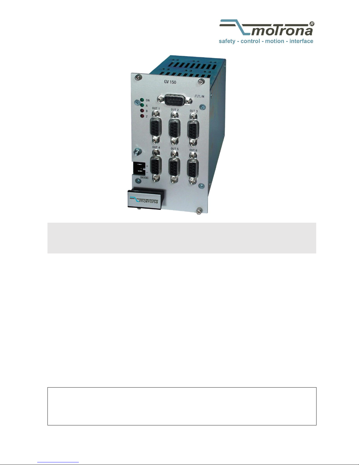
GV150 / GV151
Impulse amplifier and splitter for incremental encoder signals
Product features:
Impulse input (A, /A, B, /B, Z, /Z, TTL level or HTL level)
Potential separation by high speed optocouplers
6 output channels, each (A, /A, B, /B, Z, /Z)
Frequency range from 0 up to 400 kHz
Front LED’s for indication of input pulses A, B and Z
Elimination of noise and cross talking on transmission lines
Closed aluminum cassette for mounting in 19"racks
or snap fitting with top hat rails (option SM)
18 to 30 VDC power supply
Available devices:
GV150: All 6 output channels with TTL / RS422 level
GV151: All 6 output channels individually programmable to either TTL or HTL level
3046 Home Road. Powell, OH 43065 P: (740) 917-5781 F: (740) 917-5791 www.GenesisAutomationOnline.com Sales@GenesisAutomationOnline.com
www.GenesisAutomationOnline.com
Page 2

Gv150_02c_oi_e.doc / Nov-15 Page 2 / 9
Version:
Description:
GV15002B/hk_03/2008
First motrona edition with A5 brochure format
Gv150_02c_oi/Nov-15/ag
Manual-template, “Safety Instructions” & “Technical Specifications”
updated and “Legal notices” added.
Legal notices:
All contents included in this manual are protected by the terms of use and copyrights of motrona GmbH. Any reproduction,
modification, usage or publication in other electronic and printed media as well as in the internet requires prior written
authorization by motrona GmbH.
Table of Contents
1. Safety Instructions and Responsibility ......................................................... 3
1.1 General Safety Instructions ................................................................................... 3
1.2 Use according to the intended purpose ................................................................ 3
1.3 Installation ............................................................................................................. 4
1.4 Cleaning, Maintenance and Service Notes ........................................................... 4
2. Application and Construction ....................................................................... 5
3. Connections and Switch Settings ................................................................ 6
4. Block Diagram ............................................................................................. 7
5. Input Pin Assignment ................................................................................... 8
6. Output pin assignment ................................................................................. 8
7. Technical Specifications .............................................................................. 9
Page 3

Gv150_02c_oi_e.doc / Nov-15 Page 3 / 9
1. Safety Instructions and Responsibility
1.1 General Safety Instructions
This operation manual is a significant component of the unit and includes important rules and
hints about the installation, function and usage. Non-observance can result in damage and/or
impairment of the functions to the unit or the machine or even in injury to persons using the
equipment!
Please read the following instructions carefully before operating the device and observe all
safety and warning instructions! Keep the manual for later use.
A pertinent qualification of the respective staff is a fundamental requirement in order to use
these manual. The unit must be installed, connected and put into operation by a qualified
electrician.
Liability exclusion: The manufacturer is not liable for personal injury and/or damage to property
and for consequential damage, due to incorrect handling, installation and operation. Further
claims, due to errors in the operation manual as well as misinterpretations are excluded from
liability.
In addition the manufacturer reserve the right to modify the hardware, software or operation
manual at any time and without prior notice. Therefore, there might be minor differences
between the unit and the descriptions in operation manual.
The raiser respectively positioner is exclusively responsible for the safety of the system and
equipment where the unit will be integrated.
During installation or maintenance all general and also all country- and application-specific
safety rules and standards must be observed.
If the device is used in processes, where a failure or faulty operation could damage the system
or injure persons, appropriate precautions to avoid such consequences must be taken.
1.2 Use according to the intended purpose
The unit is intended exclusively for use in industrial machines, constructions and systems. Nonconforming usage does not correspond to the provisions and lies within the sole responsibility
of the user. The manufacturer is not liable for damages which has arisen through unsuitable
and improper use.
Please note that device may only be installed in proper form and used in a technically perfect
condition (in accordance to the Technical Specifications, see chapter 7). The device is not
suitable for operation in explosion-proof areas or areas which are excluded by the EN 61010-1
standard.
Page 4

Gv150_02c_oi_e.doc / Nov-15 Page 4 / 9
1.3 Installation
The device is only allowed to be installed and operated within the permissible temperature
range. Please ensure an adequate ventilation and avoid all direct contact between the device
and hot or aggressive gases and liquids.
Before installation or maintenance, the unit must be disconnected from all voltage-sources.
Further it must be ensured that no danger can arise by touching the disconnected voltagesources.
Devices which are supplied by AC-voltages, must be connected exclusively by switches,
respectively circuit-breakers with the low voltage network. The switch or circuit-breaker must
be placed as near as possible to the device and further indicated as separator.
Incoming as well as outgoing wires and wires for extra low voltages (ELV) must be separated
from dangerous electrical cables (SELV circuits) by using a double resp. increased isolation.
All selected wires and isolations must be conform to the provided voltage- and temperatureranges. Further all country- and application-specific standards, which are relevant for structure,
form and quality of the wires, must be ensured. Indications about the permissible wire crosssections for wiring are described in the Technical Specifications (see chapter 7).
Before first start-up it must be ensured that all connections and wires are firmly seated and
secured in the screw terminals. All (inclusively unused) terminals must be fastened by turning
the relevant screws clockwise up to the stop.
Overvoltages at the connections must be limited to values in accordance to the overvoltage
category II.
For placement, wiring, environmental conditions as well as shielding and earthing/grounding of
the supply lines the general standards of industrial automation industry and the specific
shielding instructions of the manufacturer are valid. Please find all respective hints and rules on
www.motrona.com/download.html --> “[General EMC Rules for Wiring, Screening and
Earthing]”.
1.4 Cleaning, Maintenance and Service Notes
To clean the front of the unit please use only a slightly damp (not wet!), soft cloth. For the rear
no cleaning is necessary. For an unscheduled, individual cleaning of the rear the maintenance
staff or assembler is self-responsible.
During normal operation no maintenance is necessary. In case of unexpected problems, failures
or malfunctions the device must be shipped for back to the manufacturer for checking,
adjustment and reparation (if necessary). Unauthorized opening and repairing can have
negative effects or failures to the protection-measures of the unit.
Page 5

Gv150_02c_oi_e.doc / Nov-15 Page 5 / 9
2. Application and Construction
The unit is used to increase the drive capability of existing encoder signals and to distribute the
signals to several channels. At the same time it provides potential separation between source
and target lines as well as level conversion.
In general, an incremental encoder output is limited to drive currents of 20 mA only on it's
impulse lines. The GV150 amplifiers increase the Fan-Out to 6 channels, each loadable with 20
respectively. 30 mA per line. The units can be used for encoder pulse transmission and for data
transmission applications as well.
Standardly GV150 and GV151 provide TTL (RS422) inputs (A, /A, B, /B, Z, /Z)
With option HTLIN1, the input is set to HTL level (12 … 30 V), and only the signals
A, B and Z are necessary (no inverted signals).
With option HTLIN2, the input is also set to HTL level (12 … 30 V), but all signals
must be applied (A, /A, B, /B, Z, /Z).
Each of the 6 output channels generates the signals (A, /A, B, /B, Z, /Z).
- GV150 provides always TTL/ RS422 standard and
- GV151 has individually programmable output levels TTL or HTL
Page 6

Gv150_02c_oi_e.doc / Nov-15 Page 6 / 9
3. Connections and Switch Settings
a. The unit is supplied by a power connector on the front side.
The power supply range is 18 … 30 VDC.
b. For operation without potential separation, positions 3 and 4 of the internal DIL switch
S1 can be set to "ON". This will connect the input GND to the output GND and to the
Minus potential of the power supply
c. Pin 4 of the input connector provides an auxiliary voltage output, when the DIL-switch
positions 1 and 2 are set to "ON".
When DIL-switch positions 1 and 2 are set to "ON", never any external voltage
must be applied to pin 4!
The aux. output voltage is 5.5 V / 300 mA with TTL inputs and 24 V / 300 mA with options
HTLIN1 and HTLIN2.
24VDC
5
out
Output
GND GND
4
3
2
1
5
IN
4
Opto
Input
+
-
+ 24V (HTL)
+ 5V (TTL)
S1
S1
220 R (TTL)
1K5 (HTL)
Werkseinstellung:
Factory setting:
1OFF, 2OFF
3 ON, 4 ON
All DIL switches become accessible when you remove the right hand side plate.
S2 S3
S1
1234
12345678 1234
With GV151 only
LED "On”
LED input pulses A
LED input pulses B
LED Input pulses Z
Page 7

Gv150_02c_oi_e.doc / Nov-15 Page 7 / 9
4. Block Diagram
Power
+24V
OUT 1
OUT 2
OUT 3
OUT 4
OUT 5
OUT 6
+5V
24 VDC
GND
OPTO
+
-
4
3
GND
A
A
B
B
Z
Z
GND
A
A
B
B
Z
Z
GND
A
A
B
B
Z
Z
GND
A
A
B
B
Z
Z
GND
A
A
B
B
Z
Z
GND
A
A
B
B
Z
Z
6
5
8
7
2
1
4
3
S2
2
1
+5V
2143
+5V
A
A
B
B
Z
Z
GND
S3
S1
(GV150-1)
GV150
GV150-1
GV150
GV151
GV151
Page 8

Gv150_02c_oi_e.doc / Nov-15 Page 8 / 9
5. Input Pin Assignment
(SUB-D-9 male on the unit) * See DIL switch S1
1 2 3 4 5
6 7 8 9
AAB
+5,5V
GND
*)
*)
Z Z
B
Standard TTL
1 2 3 4 5
6 7 8 9
AB
+24V
GND
*)
*)
Z
Option HTLIN1
1 2 3 4 5
6 7 8 9
AAB
+24V
GND
*)
*)
Z Z
B
Option HTLIN2
6. Output pin assignment
(SUB-D-9 female on the unit)
5 4 3 2 1
9 8 7 6
AA
GND
1K
B
B +5V Z Z
1 2 3 4 5 6 7 8 1 2 3 4
H
T
L
T
T
L
H
T
L
T
T
L
H
T
L
T
T
L
H
T
L
T
T
L
H
T
L
T
T
L
H
T
L
T
T
L
O
u
t
p
u
t
1
O
u
t
p
u
t
2
O
u
t
p
u
t
3
O
u
t
p
u
t
4
O
u
t
p
u
t
5
O
u
t
p
u
t
6
S2 S3
ON
OFF
(GV151)
With GV151, the desired output level (TTL/HTL) can be selected by setting the associated
position of the DIL switch to „ON“ (with the other position OFF).
Setting both TTL and HTL to ON at a time would result in HTL output.
For safety reasons, the default factory setting is always TTL like shown above.
Page 9

Gv150_02c_oi_e.doc / Nov-15 Page 9 / 9
7. Technical Specifications
Power supply:
Input voltage:
Protection circuit:
Ripple:
Consumption:
Connections:
18 … 30 VDC
reverse polarity protection and potential separation (switchable)
≤ 10 % at 24 VDC
approx. 200 mA (unloaded)
1.5 m supply-cable-set (2 lines) with coded plug connector
Encoder supply:
Output voltages:
Output current:
Availability:
Connections:
TTL: 5.5 VDC (standard) or
HTL: 18 … 30 VDC (optional)
max. 300 mA
switchable by DIL-switch
SUB-D connector (male), 9-pin
Incremental input:
Input levels:
Channels:
Frequency:
Internal resistance:
Connections:
TTL / RS422 (standard): LOW = 0 … 1.5 V, HIGH = 3 … 5.5 V
HTL1IN / HTL2IN (option): LOW = 0 … 4 V, HIGH = 11 … 30 V
TTL / RS422 (standard): A, /A, B, /B, Z, /Z
HTL1IN (option): A, B, Z
HTL2IN (option): A, /A, B, /B, Z, /Z
TTL output: 400 kHz HTL output: 250 kHz
TTL / RS422 (standard): Ri ≈ 220 Ohm
HTL1IN / HTL2IN (option): Ri ≈ 1.5 kOhm
SUB-D connector (male), 9-pin
Incremental outputs:
Number of outputs
Signal levels:
Channels:
Output current:
HTL output driver:
Signal delay time:
Protection circuit:
Connections:
6
GV150: TTL / RS422
GV151: HTL (18 … 30 V)
A, /A, B, /B, Z, /Z
GV150: max. 20 mA (per output)
GV151: max. 30 mA (per output)
push-pull
GV150: approx. 200 ns
GV151: approx. 700 ns
durable short circuit proof
SUB-D connector (female), 9-pin
Display components:
Number/type:
Functions:
4 LED, 2 x green and 2 x red
each 1 x operation and input pulses A, B, Z
Housing:
Material:
Mounting:
Dimensions (w x h x d):
Protection class:
Weight:
galvanized sheet steel housing with aluminum front-plate
Standard: 19"rack
Option SM: snap fitting on 35 mm top hat rail (EN 60715)
4TE x 3HE resp. 70 x 129 x 175 mm / 2.756 x 5.079 x 6.890 inch
IP20
approx. 650 g
Temperature range:
Operation:
Storage:
0 °C … +45 °C / +32 … +113 °F (not condensing)
-25 °C … +70 °C / -13 … +158 °F (not condensing)
Conformity & standards:
EMC 2004/108/EC:
Guideline 2011/65/EU:
EN 61000-6-2, EN 61000-6-3, EN 61000-6-4
RoHs-conform
3046 Home Road. Powell, OH 43065 P: (740) 917-5781 F: (740) 917-5791 www.GenesisAutomationOnline.com Sales@GenesisAutomationOnline.com
 Loading...