

Page 1
control – motion – interface
FM 260
Impulse and Frequency Multiplier for Use with
Incremental Encoders and Sensors
Universal inputs for incremental encoder signals A, B, Z or A, /A, B, /B, Z, /Z
with either TTL level or RS422 format or HTL level
Unit to multiply the input impulses with a proportional factor F1
and a reciprocal factor F2, both adjustable in a range of 0.005 to 9.9999
Error-free multiplication with accurate impulse count on input and output,
therefore no cumulative errors, even not with encoder vibration or frequent change of
direction of rotation
Frequency range 1 MHz (input and output), programmable index pulse output
Serial interface and USB port for communication with remote units and PC
Operating Instructions
FM26001c_e.doc / Nov-11 Page 1 / 27
Page 2

Safety Instructions
Version:
Description
:
This manual is an essential part of the unit and contains important hints about
function, correct handling and commissioning. Non-observance can result in
damage to the unit or the machine or even in injury to persons using the
equipment!
The unit must only be installed, connected and activated by a qualified electrician
It is a must to observe all general and also all country-specific and application-
specific safety standards
When this unit is used with applications where failure or maloperation could cause
damage to a machine or hazard to the operating staff, it is indispensable to meet
effective precautions in order to avoid such consequences
Regarding installation, wiring, environmental conditions, screening of cables and
earthing, you must follow the general standards of industrial automation industry
- Errors and omissions excepted –
FM26001a/af/hk/mb/Juni08 First edition
FM26001b/hk/April09 Hint concerning shape of output signals
FM26001c_pp_11/11 Completion of chapter 8 : encoder outputs
FM26001c_e.doc / Nov-11 Page 2 / 27
Page 3

Table of Contents
1. Introduction ................................................................................................. 4
2. Application Examples .................................................................................. 5
2.1. PPR numbers which are not available with encoders...........................................5
2.2. Fine tuning of circumference and attrition of a measuring wheel........................5
2.3. Gearboxes with irrational or recurrent gear ratios ...............................................6
3. Terminal Assignments and Connections ...................................................... 7
3.1. Block Diagram .......................................................................................................8
3.2. Power Supply.........................................................................................................8
3.3. Auxiliary Encoder Supply Output...........................................................................8
3.4. Impulse Inputs for Encoders and Sensors.............................................................8
3.5. Control Inputs ........................................................................................................9
3.6. Serial Interface......................................................................................................9
3.7. USB Port ................................................................................................................9
3.8. Impulse Outputs ....................................................................................................9
4. LCD Display and Front Keys ....................................................................... 10
5. Keypad Operation ...................................................................................... 11
5.1. Normal Operation................................................................................................11
5.2. Keypad Interlock..................................................................................................11
5.3. General Setup Procedure ....................................................................................12
5.4. Changing Parameters on the Setting Level.........................................................12
5.5. Return from the Menu, Time-Out Function .........................................................13
5.6. Reset all Parameters to Factory Default Values .................................................13
6. Menu Structure and Parameter Description ............................................... 14
6.1. Survey of Menus .................................................................................................14
6.2. Description of the parameters ............................................................................15
7. Clarification of Command Functions........................................................... 20
8. Technical Specifications and Dimensions .................................................. 21
9. Appendix ................................................................................................... 23
9.1. Serial Communication Protocol...........................................................................23
9.2. Installation of the USB Driver .............................................................................24
9.3. Serial Code List ...................................................................................................26
FM26001c_e.doc / Nov-11 Page 3 / 27
Page 4

1. Introduction
Factor 1
Factor 2
The FM 260 unit has been designed for use as a programmable impulse multiplier of incremental
encoder signals. Encoder impulses applied to the input will be scaled by means of two adjustable
Factors, and the resulting impulse sequence will appear at the output with only a few microseconds
of delay.
The output frequency fout may be higher or lower than the input frequency fin, depending on the
factor settings. In principle the function of the unit allows conversion of any input frequency inside
the specified range to any other proportional output frequency.
This unit considers every individual impulse, with consideration of the counting direction indicated by
the quadrature A/B input phase. The number of generated output pulses is therefore accurate and
error-free with regard to input count and Factor setting, even with vibrations and changes of the
direction.
fout = fin
(Factor 1 = 0,0005 - 9,9999, Factor 2 = 0,0005 – 9,9999 )
The five-decade resolution of both factors provides precision scaling of the desired output with
regard to the input signal.
Moreover, if applicable, a marker pulse with programmable ppr number can be generated, either
with or without synchronization to an input index pulse.
Setup of the unit requires setting of the few parameters only, which may be done by means of the
front keys and the LCD menu or via PC using the serial link or the USB port of the unit.
For all PC operation the operator software OS32 is suitable (included in delivery).
Some applications may require changing settings during operation (e.g. change of the input/output
ratio "on the fly"). This is easily possible via serial link, via USB or by means of a PROFIBUS network
(gateway PB251 needed).
The versatile impulse input of the unit can be set for use with all common standard encoders or
sensors. Independent of the selected input format the output provides always a full set of the signals
A, /A, B, /B and Z, /Z. The output stages are push-pull type and provide an output level of 5 – 30
volts corresponding to the remote supply voltage applied to the output drivers.
Concerning the shape of the output signals, please observe the special hint
given on page 6 of this manual
FM26001c_e.doc / Nov-11 Page 4 / 27
Page 5
2. Application Examples
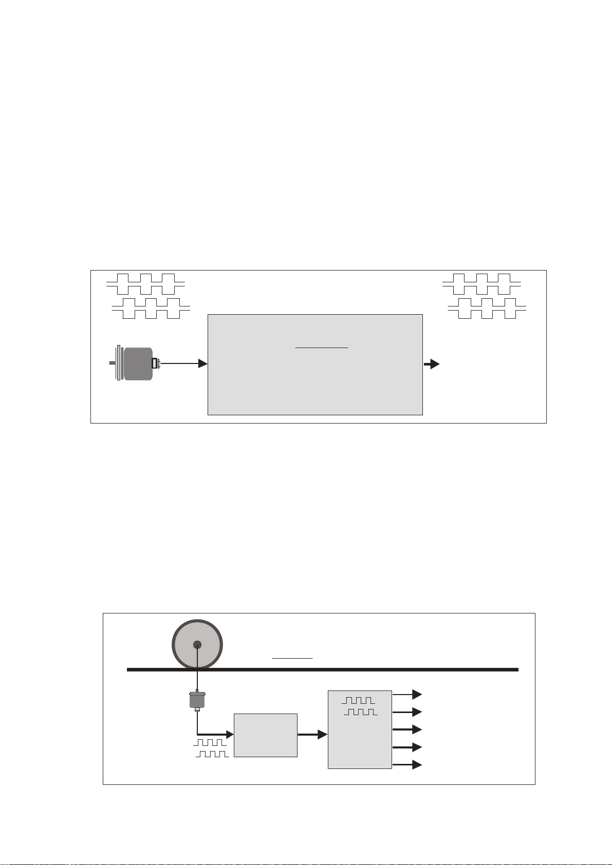
2.1. PPR numbers which are not available with encoders
Some applications may require an encoder with a ppr number that is not available on the market, or
which is difficult to get. In such cases the FM 260 multiplier will be able to generate your required
ppr number from the output of any standard encoder.
The example shows how to simulate an encoder with the unusual number of 5431 pulses/rev. from a
standard 4096 ppr encoder, just by setting Factor 1 to 0.5431 and Factor 2 to 0.4096.
This principle even allows encoder operations with non-integer ppr numbers, e.g. to make an encoder
with 100.4 impulses per revolution..
A, /A, B, /B, Z, /Z
Encode r with
4096ppr
In
0,5431
x
0,4096
(Example)
Out
A, /A, B, /B,Z, /Z
5431 ppr
2.2. Fine tuning of circumference and attrition of a measuring wheel
Many times, in extensive production lines, only one single encoder with measuring wheel is
responsible for the control of several different follower machines and controls. Where an attrition of
the wheel would require readjustments in order to keep the accuracy, this would need to happen
individually on every of the following machines and related controls (provided that such kind of
tuning facility is available at all).
With use of a FM 260 multiplier there is an easy way of fine-tuning of the whole line in one central
location only. If applicable, even remote tuning is possible via PLC and serial communication or via
PROFIBUS.
Measuring wheel
Material line
Encoder
FM 260
Fine tuning by changing the factor: x 0,9998 ... 0,9999 ... 1,0000 ... 1,0001 etc.
FM26001c_e.doc / Nov-11 Page 5 / 27
Impulse
Splitter
Folower machine 1
Follower machine 2
Follower machine 3
Control system
PLC
Page 6
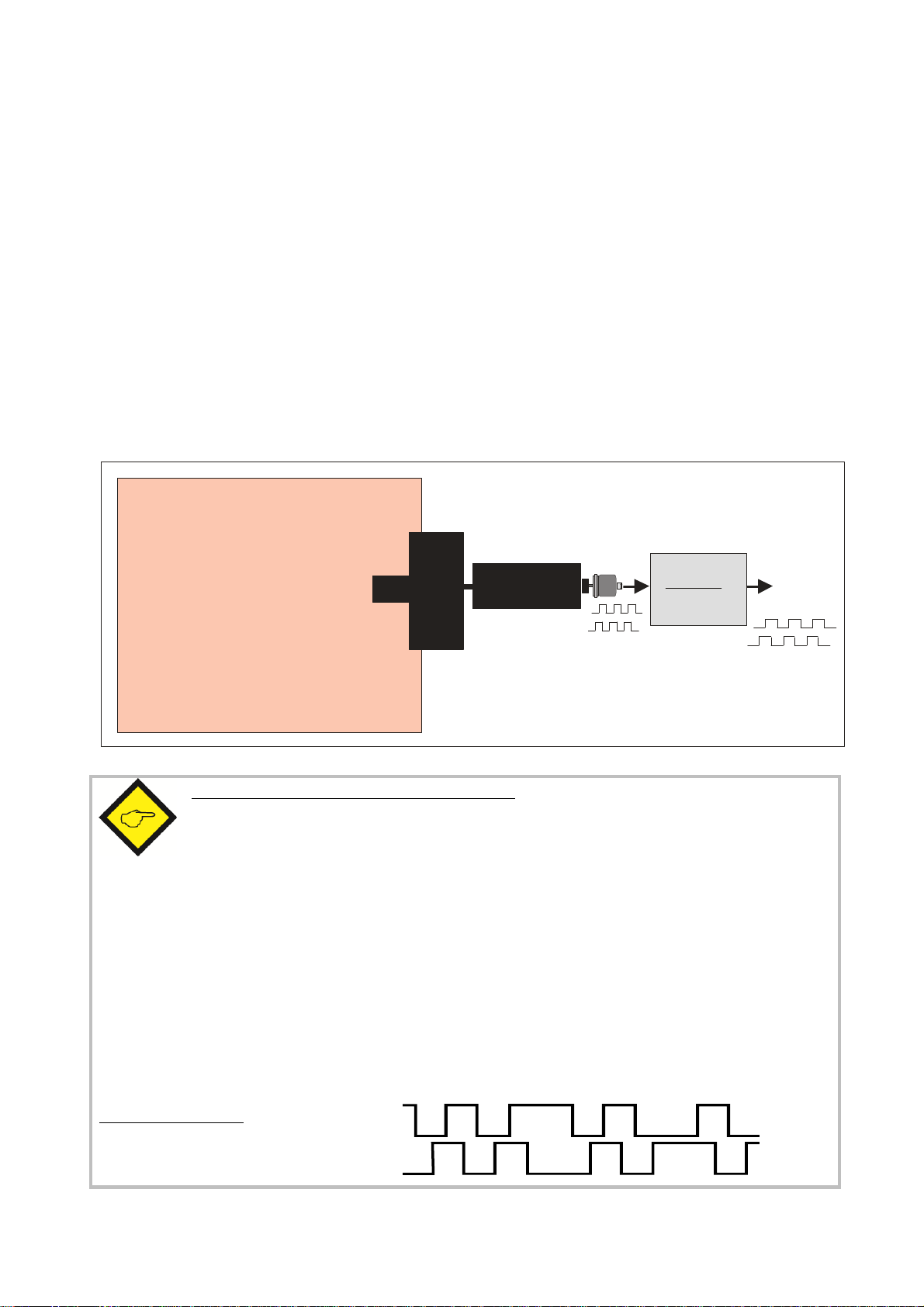
2.3. Gearboxes with irrational or recurrent gear ratios
In practical applications we often find gearings that cannot be properly expressed by a decimal
number (e.g. with a pinion gear of 25 : 9 pinions the decimal expression ratio is 2.7777777.....)
This will cause problems with all position-related or angle-related applications using a decimal ratio
setting. Cumulating errors will result when we set the ratio only with 3 or 4 decimal positions while
the following positions remain unconsidered.
For this reason a user may be forced to mount an extra encoder on the site beyond the gear (which
may be very laborious or even impossible under certain conditions), even though there may already
be an encoder available on the motor site.
Since FM 260 provides a proportional and a reciprocal factor, problems with irrational gear ratios
may be easily solved just by setting the real fraction values according to the number of pinions
involved (i.e. 25 : 9 respectively 2.5000 : 0.9000) rather than imperfect decimal values like 2.777)
Explosive environment or
high-temperature environment
where mounting of an encoder
is problematical or impossible
Motor
Encoder
0.9000
2.5000
FM 260
Pinion gear
25 : 9
Hint concerning the shape of the output signals:
As a result of the digital synthesis of the output frequency, the duty cycle on the output site in
general is different from 1:1. Therefore, also the phase displacement A/B cannot be 90° all the
time. These facts however, in general, do not mean any limitations or restrictions with
practical applications, since the signals will be accepted by practically all industrial counters,
drives or other target units.
At any time it is ensured that
the average frequency over several periods is accurately consistent with the frequency expected from
the input and the ratio setting
the phase displacement will at least be 45° which is more than enough for every industrial phase
discriminator to operate correctly
the number of output pulses corresponds exactly to the number of input pulses with consideration of
the conversion ratio
Typical output signal:
FM26001c_e.doc / Nov-11 Page 6 / 27
Page 7
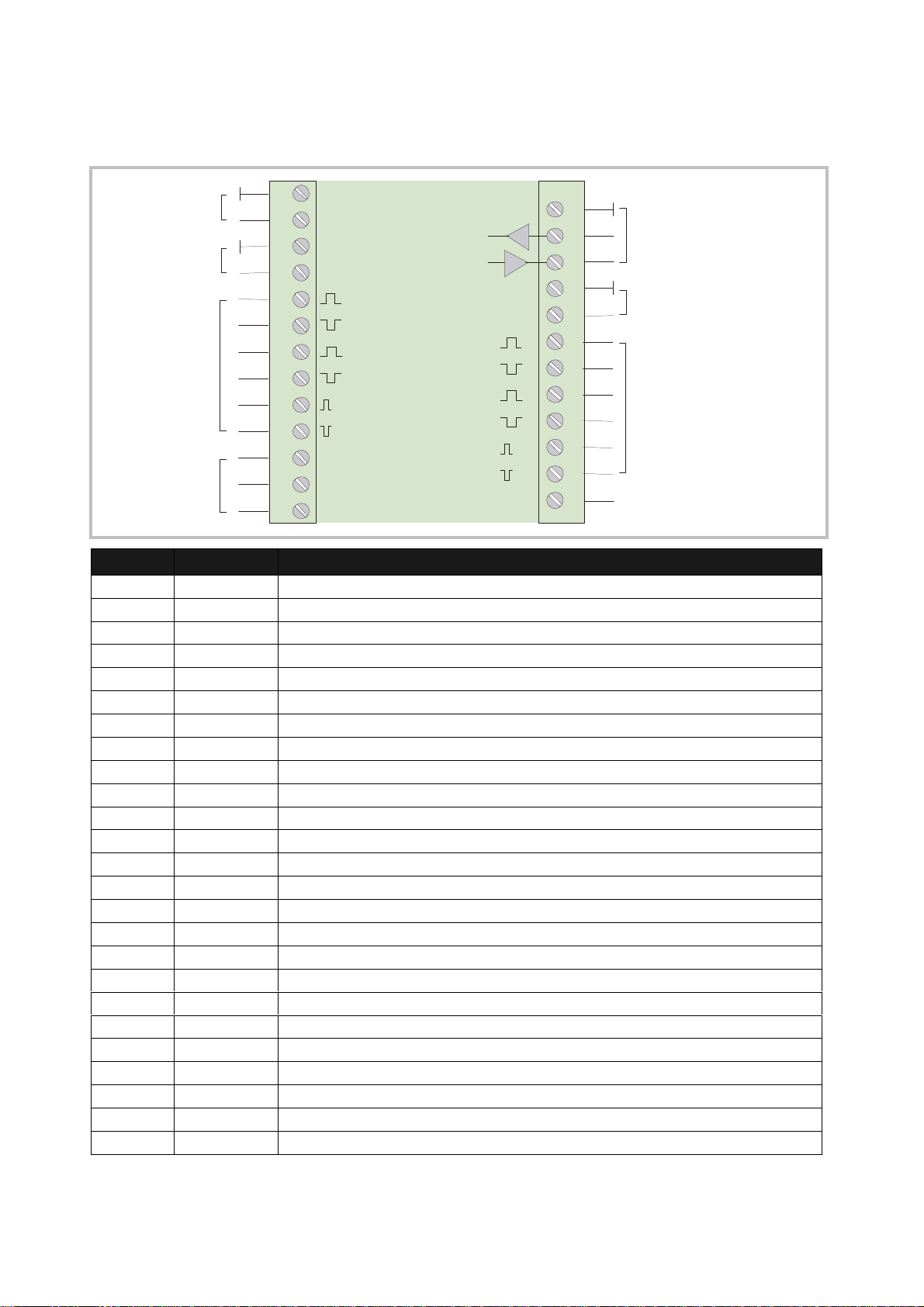
3. Terminal Assignments and Connections
Terminal
Appellation
Function
1 2 3 4 5 6 7 8 9 10 11 12 13
Power supply
11 - 30VDC
Aux. output
+5,2V
Impulse inputs
for encoders
and sensors
Control inputs
GND (-)
+Power
GND
+5,2V
A
/A
B
/B
Z
/Z
Cont.1
Cont.2
Cont.3
GND
RxD
TxD
GND
COM+
Cont.4
A
/A
B
/B
Z
/Z
14 15 16 17 18 19 20 21 22 23 24 25
Serial RS232
interface
Remotesupply 5 - 30 V
for output stages
Impulse outputs
Control input
01 GND Minus of power supply, common GND potential
02 +Power Plus of power supply, 11 – 30 volts DC
03 GND Common GND
04 +5,2V Auxiliary output 5,2 V / 200 mA for encoder supply
05 A Impulse input, channel A
06 /A Impulse input, channel /A (=A inverted)
07 B Impulse input, channel B
08 /B Impulse input, channel /B (=B inverted)
09 Z Marker pulse input Z
10 /Z Marker pulse input /Z (=Z inverted)
11 Cont. 1 Control input with programmable function
12 Cont. 2 Control input with programmable function
13 Cont. 3 Control input with programmable function
14 GND Common GND
15 RXD Serial RS232 interface, Receive Data (input)
16 TXD Serial RS232 interface, Transmit Data (output)
17 GND Common GND
18 COM+ Remote supply input for output stages (terminals 19 – 24), 5 – 30 VDC
19 A Impulse output, channel A
20 /A Impulse output, channel /A (=A inverted)
21 B Impulse output, channel B
22 /B Impulse output, channel /B (=B inverted)
23 Z Marker impulse output, Z
24 /Z Marker impulse output, /Z (=Z inverted)
25 Cont. 4 Control input with programmable function
FM26001c_e.doc / Nov-11 Page 7 / 27
Page 8
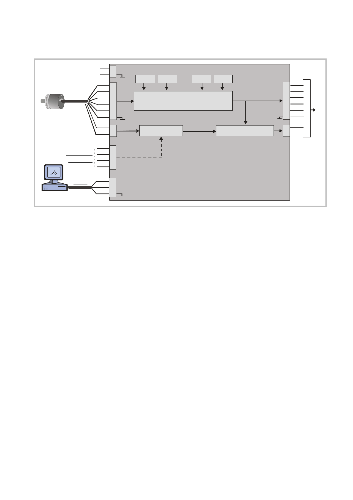
3.1. Block Diagram
Power s u pply
11 - 30 VDC
In
Re set, Trim ,
F reeze etc.
RS232
+5,2
/A
/B
Cont1
Cont2
Con t3
Con t4
RxD
T xD
G ND
2
1
4
A
5
6
B
7
8
-
3
Z
9
/Z
10
11
12
13
25
15
16
14
Impulse Processing
Trim + Trim -Factor 2Facto r 1
Sync. pulse
Com +
18
A
19
/A
20
B
21
/B
22
17
23
Marker pulse generatorG ate Func tion
24
/Z
Out
-
Z
3.2. Power Supply
The units require a DC supply from 11 to 30 volts which must be applied to terminals 1 and 2.
Depending on the input voltage level and internal states, the power consumption may vary and lies in
a range of about 65 mA with a 24 volts input (plus encoder currents taken from the auxiliary voltage
output).
3.3. Auxiliary Encoder Supply Output
Terminals 3 and 4 provide an auxiliary output of +5.2 VDC / 200 mA for supply of encoders and
sensors.
3.4. Impulse Inputs for Encoders and Sensors
The setup menu of the unit allows individual setting of the desired characteristics of the signal
inputs. According to the application the units will accept single-channel signals (input A only with no
direction information) as well as dual channel signals A/B including information of the direction of
rotation. The following input formats and levels are acceptable:
symmetric differential input with RS422 format or TTL inputs A, /A, B, /B
asymmetric (single-ended) TTL levels (A and/or B only without inverted channels)
HTL level 10 – 30 volts, alternatively differential (A, /A, B, /B) or single-ended
(A and B only, without inverted channels)
Signals from proximity switches or photocells providing HTL level (10-30 V)
NAMUR (2-wire) signals
The maximum input frequency of the unit is specified to 1 MHz.
The use of the marker pulse inputs Z, /Z is optional.
FM26001c_e.doc / Nov-11 Page 8 / 27
Page 9
3.5. Control Inputs
235
RxD
RxD
TxD
TxD
GND
PC
(Sub-D-9)
The control inputs provide assignment of programmable functions like keypad-locking, change of the
direction A/B or freezing of the actual output frequency etc.
The inputs require HTL level 10 – 30 V (PNP, switching to +) and the input function can be set to
either "active LOW" or "active HIGH". A minimum pulse duration of 2 msec must be observed with all
commands applied to the control inputs.
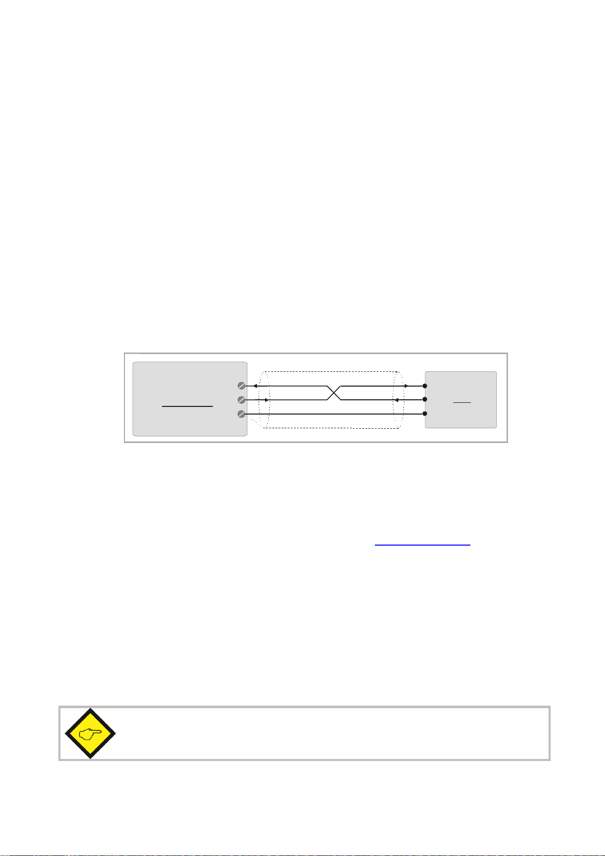
3.6. Serial Interface
The serial RS232 interface in general may be used
for easy setup and commissioning of the units (with use of the OS32 operator software)
to change settings and parameters remotely by PC or PLC during the operation
to read out internal states and actual measuring values by PC or PLC
The subsequent drawing shows how to link the unit with a PC, using the standard
9-pin Sub-D-9 connector
Schirm
15
FM 260
16
14
3.7. USB Port
The USB port provides exactly the same range of function as the serial interface. For USB connection
you need a standard USB cable with a "Mini 5-pin" type connector on one site. Before using the USB
port it is necessary to install the driver software on the operator PC. This software is available from
the CD included to delivery, and can also be downloaded from www.motrona.com.
The USB driver software is named CDM 2.04.06 WHQL Certified. zip
Please refer to the appendix chapter 9.2 of this manual for more details about USB driver installation.
3.8. Impulse Outputs
Screw terminals 19 – 24 always provide all of the output signals A, /A, B, /B, Z, /Z, even when you
do not apply inverted signals or marker pulse information to the input.
The output level (5 - 30 volts) is determined by the external voltage applied to terminal 18 (COM+).
The unit uses push-pull output stages for all channels, and the maximum output frequency is 1 MHz.
Please note that neither the input frequency nor the resulting output frequency must
exceed the maximum value of 1 MHz at all times.
FM26001c_e.doc / Nov-11 Page 9 / 27
Page 10

4. LCD Display and Front Keys
Actual conversion error
The units provide a back-lit LCD display with 2 lines at 16 characters each, and four keys for setup
and command control.
During the setup procedure the LCD display indicates the menu with all parameter texts and the set
values of the parameters.
During normal operation, the LCD display indicates the following information:
(input pulses / output pulses)
+0.0000 INC
I: LLHH f > 2000i
Frequency indicator
(input > or < frequency set point))
I: Inputs
Actual state of the 4 control inputs
L = Low, H = High
FM26001c_e.doc / Nov-11 Page 10 / 27
Page 11

5. Keypad Operation
PROG
UP
DOWN
ENTER
Using the Hardware Latch function may accidentally cause a total locking of all
A summary of all parameters and a detailed description of parameter functions is available under
section 6.
For all operation, the units provide four front keys which subsequently will be named as shown
below:
P
The key functions depend on the actual operating state of the units. Basically we have to distinguish
between Normal Operation and Setup Operation
5.1. Normal Operation
While in normal operation state, the units process the input frequency to an output frequency
according to the selected operational parameters and settings. Each of the front keys provides the
command functions as attached to it upon setup in the "Command Menu"
5.2. Keypad Interlock
There is a 3-stage conception to protect the keys against unauthorized changes of the configuration
respectively against activation of commands.
Stage Protected Range Protection
by
Change of Parameters Commands
1 --- --- permitted permitted
2 Menu Password upon
activation of menu
3 Keyboard Hardware-Latch 1 interlocked permitted
Hardware Latch 2 All functions interlocked
The "Key Pad" menu allows to define an individual password for each group of parameters. This
function can be used to provide individual access rights to different operators. Upon access to an
interlocked section the unit asks for the corresponding password. If the correct password is not
entered in time, the unit denies access and automatically returns to normal operation.
The hardware latch function can be activated and deactivated by one of the Control Inputs, or by
means of serial access to the corresponding locking register.
functions, when the Control Inputs characteristics have been set inauspiciously.
In this exceptional case you can release the key functions again by either
a) applying the correct logical state (High or Low) to the inputs
b) or resetting the parameters to their default values (see section 5.6.)
c) or change the parameters being responsible for the locking by PC
Protection of selectable parts of the menu
via password
Key Operations
permitted
FM26001c_e.doc / Nov-11 Page 11 / 27
Page 12

5.3. General Setup Procedure
Key
Menu Level
Parameter Level
Setting Level
PROG
UP
DOWN
ENTER
To change over from normal operation to the setup state, please keep down the PROG key for at
least 2 seconds. After this the menu appears and you can select one of the menu groups.
Inside each group you can select the desired parameter and edit the setting according to need. After
this you are free to edit more parameters, or to return to normal operation.
The function of the different keys during setup is shown in the table below.
Save settings and return
to normal operation
Switch over to next menu Select next parameter Increment the highlighted digit
Go back to previous menu Select previous parameter Decrement the highlighted
Switch over to the
Parameter Level of the
current menu
Return to Menu Level Check entry, store result, then
go back to Parameter Level
or scroll the setting upwards
digit or scroll the setting
downwards
Switch over to
Setting Level
Shifts the highlighted digit one
position to the left, or from
utmost left to utmost right
5.4. Changing Parameters on the Setting Level
With signed parameters, the front digit can only be changed between „+“ (positive) and „-„
(negative). The subsequent example explains how to change a parameter from originally 1024 to a
new value of 250 000.
The example assumes that you are already on the Setting Level, i.e. you have already selected the
corresponding parameter and read its actual value on the display. Highlighted (blinking) digits are
marked by background color and indicate the cursor position.
FM26001c_e.doc / Nov-11 Page 12 / 27
Page 13

No.
Display
Key action
Comment
00
00102
4
The actual value 1024 is displayed, with
4 x
Change last digit to 0
00102
0
Shift cursor to left
0010
2
0
2 x
Change highlighted digit to 0
0010
0
0
Shift curser to left by 2 pos
itions
00
1
000
Change highlighted digit to 0
00
0
000
Shift cursor to left
000000
5 x
Change highlighted digit to 5
050000
Shift cursor to left
0
50000
2 x
Change highlighted digit to 2
2
50000
Save new setting and return to
Power the unit down
Switch power on with both keys held down
01
02
03
the last digit blinking
04
05
06
07
08
09
10
2 x
Parameter Level
5.5. Return from the Menu, Time-Out Function
At any time the PROG key changes the Menu by one level backwards or fully back to the normal
operation mode. The menu also switches automatically one level backwards, every time when for 10
seconds no key has been touched (Time-Out-Function).
5.6. Reset all Parameters to Factory Default Values
If applicable, the whole set of parameters can be reset to factory default values (e.g. because a code
for the keypad interlocking has been forgotten, or because the unit does no more work correctly for
reasons of bad settings). All default values are indicated in the following parameter tables.
To execute this Reset procedure, you have to take the following steps:
Press
Where you decide to execute this action, please be aware that all parameter
settings will be lost, and you will have to repeat the whole setup procedure
FM26001c_e.doc / Nov-11 Page 13 / 27
and
simultaneously
Page 14

6. Menu Structure and Parameter Description
All parameters are combined to groups, arranged in several menus. You must only set those
parameters which are really relevant for your individual application.
6.1. Survey of Menus
This section provides an overview of the menus and their assignments to the different functions of
the units. The menu names are printed bold, and associated parameters are arrayed directly under
the menu names.
Menu texts are in English, according to the presentation on the LCD display
No.: Factor Setting No.: Command Setting
0 Factor 1 31 Key Up Func.
1 Factor 2 32 Key Down Func.
No.: General Setting 33 Key Enter Func.
5 Encoder Proper 34 Input 1 Config.
6 Direction 35 Input 1 Function
7 Z-Impulse 36 Input 2 Config.
8 Burst 37 Input 2 Function
9 Input Z Config. 38 Input 3 Config.
No.: Display Setting 39 Input 3 Function
14 Update Time 40 Input 4 Config.
15 Display Mode 41 Input 4 Function
16 Display Factor No.: Serial Setting
17 Display Multi. 45 Unit Number
18 Inhibit Overflow 46 Serial Baud Rate
No.: Keypad Setting 47 Serial Format
21 Protect Factor 48 Serial Protocol
22 Protect General 49 Serial Time (s)
23 Protect Display 50 Register Code
24 Protect Keypad No.: Trim Setting
25 Protect Command 54 Trim Time
26 Protect Serial
27 Protect Trim
FM26001c_e.doc / Nov-11 Page 14 / 27
Page 15

6.2. Description of the parameters
6.2.1. Setting of the frequency conversion ratio
Factor Settings Range Default
Factor 1 (proportional factor) 0.0005 … 9.9999 1.0000
Factor 2 (reciprocal factor) 0.0005 … 9.9999 1.0000
6.2.2. General settings
General Settings Range Default
Encoder Proper (properties of the input encoder) 0 … 7 0
0 A, /A, B, /B, quadrature, differential HTL or TTL or RS 422
1 A, B, quadrature, single-ended, HTL level, NPN *)
2 A, B, quadrature, single-ended, HTL level, PNP
3 A, B, quadrature, single-ended, TTL level
4 A, /A = impulse, B, /B = direction, differential HTL or TTL or RS422
5 A = impulse, B = direction, single-ended, HTL level, NPN *)
6 A = impulse, B = direction, single-ended, HTL level, PNP
7 A = impulse, B = direction, single-ended, TTL level
Direction (definition of the A/B direction) 0 … 1 0
0 forward when A leads B
1 forward when B leads A
Z-Impulse
Number of encoder impulses between two marker pulses on output
Burst
Sets the control loop for correction of temporary conversion errors. This
setting can be increased if under special conditions the unit would
frequently display „Overflow“.
(see also parameter „Inhibit Overflow“)
Input Z Config *)
Determines whether or not the marker pulse output should be referenced
to the input marker, and which of the hardware inputs will be used for the
Gate function
0 no gate function
1 a High signal on input Cont.1 and the rising edge of the input marker
are used to synchronize the output marker.
2 as above, but gating by a High signal on input Cont.2
3 as above, but gating by a High signal on input Cont.3
4 as above, but gating by a High signal on input Cont.4
5 as above, but gating by a Low signal on input Cont.1
6 as above, but gating by a Low signal on input Cont.2
7 as above, but gating by a Low signal on input Cont.3
8 as above, but gating by a Low signal on input Cont.4
1 … 50,000 1,000
10 … 100 20
0 … 8 0
When any of the control inputs (Cont.1 – Cont.4) is used for referencing of the marker pulse
(Parameter „Input Z Config“ ≠ 0), no further assignment of a command will be allowed to
this input (i.e. Input X Func. must be 0 , see 6.2.5)
FM26001c_e.doc / Nov-11 Page 15 / 27
Page 16

*) With settings HTL / NPN the input terminals are connected to the power supply voltage
of the unit (+24V) via internal pull-up resistors. For this reason it is advisable to first set the
encoder properties correctly, prior to connecting TTL encoders to the unit.
Setting HTL / NPN is also suitable for use with NAMUR (2-wire) proximities.
(connect the positive wire of the sensor to the input terminal and the negative wire to GND))
6.2.3. Display settings
Display Settings Range Default
Up-Date-Time
Update time of the LCD display (sec.)
Display Mode
Scaling of the actual conversion error shown on the LCD display *)
0 Number of impulses that output lags input, format X.XXXX inc.
1 Number of impulses that output lags input, format XXXXX inc.
2 Conversion error converted to angular degrees, format X.XX °
Parameter „Display Factor“ must be set to the appropriate number of
ppr for this
3 Error display according to user scaling, format XXXX units.
tiDisplayMulError
Display
Display Factor
Parameter for error scaling with modes 2 + 3
Display Multi.
Parameter for error scaling with mode 3
Inhibit Overflow
Sets the display mode of an overflow message
0 „Overflow“ is latched in display until cleared by a Reset command
1 „Overflow“ is displayed while an overflow situation exists and
disappears automatically after catch-up of the error
2 No overflow message will appear
.
torDisplayFac
0.05 … 1.00 0.25
0 … 3 0
1 ... 99,999 100
1 ... 999 100
0 … 2 0
6.2.4. Keypad access protection by password
Key-Pad Settings (Code for the corresponding menu) Range Default
Protect Menu 01 (Factor Settings) 0 = no password
Protect Menu 02 (General Settings) 0
Protect Menu 03 (Display Settings) 0
Protect Menu 04 (Key-Pad Settings) 0
Protect Menu 05 (Command Settings) 0
Protect Menu 06 (Serial Settings) 0
*) The conversion error indicates by how many impulses the output actually lags the input. Since in general any
lagging error will be compensated within microseconds only, the display of conversion error and overflow
message are only of interest under special conditions.
FM26001c_e.doc / Nov-11 Page 16 / 27
protection
1 … 999.999 =
password for the
corresponding menu
0
Page 17

6.2.5. Assignment of commands to the keys and the control inputs
Command Setting Range Default
Key Up Func. (additional function of the UP key) 0 … 8 0
0 no command assigned
1 Send Data
2 Disable Output
3 Freeze Output
4 Direction
5 Reference Z
6 Reset
7 Trim -
8 Trim +
Key Down Func. (similar to Key UP, but additional function of the Down key) 0 … 8 0
Key Enter Func. (similar to Key UP, but additional function of the Enter key) 0 … 8 0
Input 1 Config. (Switching characteristics of Input "Cont.1") 0 … 1 0
0 Static Low
1 Static High
Input 1 Func. (control function of input „Cont.1“) 0 … 9 0
0 no command assigned
1 Send Data
2 Disable Output
3 Freeze Output
4 Direction
5 Reference Z
6 Reset
7 Trim -
8 Trim +
9 Key Lock
Input 2 Config. (see Input 1 Config. but "Cont.2") 0 … 1 0
Input 2 Func. (see Input 1 Func. but "Cont.2") 0 … 9
Input 3 Config. (see Input 1 Config. but "Cont.3") 0 … 1 0
Input 3 Func. (see Input 1 Func. but "Cont.3") 0 … 9
Input 4 Config. (see Input 1 Config. but "Cont.4") 0 … 1 0
Input 4 Func. (see Input 1 Func. but "Cont.4") 0 … 9 0
For more details
about the function of
these commands
please refer to
chapter 7.
For more details
about the function of
these commands
please refer to
chapter 7.
When any of the control inputs (Cont.1 – Cont.4) is used for referencing of the marker pulse
(Parameter „Input Z Config“ ≠ 0, see 6.2.2), no further assignment of a command will be
allowed to this input (i.e. Input X Func. must be 0)
FM26001c_e.doc / Nov-11 Page 17 / 27
Page 18

6.2.6. Serial communication settings
Serial
-
Menu
Code
Setting Range
Default
Unit Number
(
Serial Baud Rate
(
Serial Format
(
Serial transmissions will operate in either the “PC Mode“ or in “Printer Mode“.
With “PC-Mode“, the unit receives a request string and responds with a corresponding data string.
For details of the protocol see separate description “SERPRO“.
With “Printer Mode“ the unit sends data without any request and under Timer control, as described
subsequently.
As soon as the unit receives a character, it automatically switches over to PC Mode and operates
according to protocol. When for a period of 20 sec. no character has been received, the unit switches
automatically back to “Printer Mode“ and starts cyclic data transmission again.
(Configuration of the serial link)
Serial device address)
A unit number between 11 and 99 can be assigned to each unit.
The address must not contain any zeros (0) since these addresses are
reserved for collective addressing of several units.
Transmission speed)
0= 9600 Baud
1= 4800 Baud
2= 2400 Baud
3= 1200 Baud
4= 600 Baud
5= 19200 Baud
6= 38400 Baud
Format of transmit data)
0= 7 Data, Parity even, 1 Stop
1= 7 Data, Parity even, 2 Stop
2= 7 Data, Parity odd, 1 Stop
3= 7 Data, Parity odd, 2 Stop
4= 7 Data, no Parity, 1 Stop
5= 7 Data, no Parity, 2 Stop
6= 8 Data, Parity even, 1 Stop
7= 8 Data, Parity odd, 1 Stop
8= 8 Data, no Parity, 1 Stop
9= 8 Data, no Parity, 2 Stop
„90“ 11 ... 99 11
„91“ 0..6 0
„92“ 0 ... 9 0
FM26001c_e.doc / Nov-11 Page 18 / 27
Page 19

Serial
-
Menu
(Configuration of the serial link)
Code
Setting Range
Default
Serial Protocol
Serial Timer
Register Code
Determines the sequence of characters sent, when you use the serial
output for cyclic data transmission under timer control
(xxxxxxx is the measuring value transmitted).
0= Transmission = Unit Nr. – Data, LF, CR
1= Transmission = Data, LF, CR
Setting "1" removes the unit address from the string which allows a
slightly faster transmission cycle.
Unit No.
0: 1 1 +/- X X X X X X LF CR
1: +/- X X X X X X LF CR
This register determines the cycle time in seconds for cyclic transmission
when the Printer Mode is switched on.
Range 0.001 to 9.999 seconds.
With setting “0” all cyclic transmission is switched off and the unit will
only send data upon request (PC mode)
Serial access code of the register which, in Printer Mode, should be
transmitted with every cycle.
„F3“ 0 ... 1 0
„F4“ 0 ... 9.99 0
„F5“ 0 ... 19
(:0) … (;9)
8
6.2.7. Phase Trimming
Trim Settings Range Default
Trim Time:
Time base (sec.) for adding or subtracting additional impulses to the output
frequency (differential frequency = 1/ Trim Time.
(see also chapter 7.)
0,000 … 1,000 0,100
FM26001c_e.doc / Nov-11 Page 19 / 27
Page 20

7. Clarification of Command Functions
Nr. Command Description Assignment
Keys Cont. input
0 no function The corresponding key or the corresponding control input
will not activate any command
1 Send Data Starts a serial data transmission (see 6.2.6 Serial
Protocol) where the transmit value is determined by
"Register Code".
2 Disable Output Inhibits all output function, i.e. the output frequency is
zero while this command is on
3 Freeze Output Freezes the actual output frequency, i.e. the frequency
will be constant and no more follow the input frequency
4 Direction Changes the direction of the output frequency, i.e. the
phase situation A / B will be inverted
5 Reference Z Sets the internal marker pulse generator and related
counters to zero. No marker pulse will appear at the
output while this command is active.
6 Reset Resets the actual conversion error to zero, clears the
"Overflow" message and inhibits the frequency output
(i.e. output frequency is zero)
7 Trim - *) Generates a differential frequency fdiff that is subtracted
from the regular output frequency, i.e. the number of
output pulses will be temporary scaled down by
fdiff = 1/ Trim Time,
8 Trim + *) Generates a differential frequency fdiff that is added to
the regular output frequency, i.e. the number of output
pulses will be temporary scaled up by
fdiff = 1/ Trim Time,
9 Hardware keypad
interlock
See chapter 5.2 no yes
yes yes
yes yes
yes yes
yes yes
yes yes
yes yes
yes yes
yes yes
yes yes
*) Trim functions can e.g. be used in position-related applications where it may be necessary to
temporary shift the output count with regard to the input count (e.g. to adapt the relative position
of a product to the process).
FM26001c_e.doc / Nov-11 Page 20 / 27
Page 21

8. Technical Specifications and Dimensions
Power supply
:11
VDC
-
30 VDC
Current consumption
:
approx
.65mA
with
24 VDC
Aux. output for encoder supply
:
5.2
V max. 200
mA
Control inputs
Cont
.1-Cont.4
:
Ri = 3,9 kOhm, LOW <
2,5V, HIGH > 10V
Encoder inputs
:
RS422
or differential TTL or differential HTL
Encoder
o
utput
s
Push
-
pull stages 5
–
30 V / 30 mA
Input frequency
:
RS422 und TTL
differential
: 1 MHz
Serial interface
:
RS232 / 2400
-38400baudsAmbient temperature
Operation
:0-
45°C ( 32
–
113°F)
Housing
:
Plastic housing for mounting on standard DIN rails
35 mm
Display
:
LCD
with backlight
Protection class
:
IP20
Connection termina
ls:25
screw terminals,
cross section max.
1.5 mm²
(0.0023 in²)
Conformity and standards
:EMC
89/336/E
EC:EN 61000
-6-
2
Minimum pulse duration with dynamic function: 50 µsec.
Minimum pulse duration with static signals: 2 msec.
(differential voltage mist always be > 1 V)
TTL, LOW < 0.5V, HIGH > 2,5V
HTL (NPN / PNP) Ri = 4,75 k, LOW < 4V / HIGH >10V
(short-circuit-proof)
HTL und TTL single-ended: 300 kHz
:
Storage: -25 - +70°C (-13 – 158°F)
2 lines at 16 characters each, 3,5 mm size
EN 61000-6-3
LV73/23/EEC: EN 61010-1
FM26001c_e.doc / Nov-11 Page 21 / 27
Page 22

Dimensions:
(3.583’’)91,0mm
33,0mm
51,0 mm
76,0mm
(1.299’’)
(2.001’’)
(2.992’’)
Front view
Side view
72,0mm
(2,835’’)
FM26001c_e.doc / Nov-11 Page 22 / 27
Page 23

9. Appendix
EOT
AD1
AD2
C1C2ENQ
EOT = control character (Hex 04)
ASCII Code:
EOT1100
ENQ
Hex Code:
043131303005Binary Code:
0000 0100
0011 0001
0011 0001
0011 0000
0011 0000
0000 0101
STXC1C2
x x x x x x x
ETX
BCC
STX = control character
(Hex 02)
9.1. Serial Communication Protocol
All registers are also available for serial readout by PC or PLC. For communication the unit uses the
Drivecom Protocol according to ISO 1745. All protocol details can be found in our manual
SERPRO_2a.doc which is available for download from our homepage
www.motrona.com
To request for a data transmission you must send the following request string to the unit:
AD1 = unit address, High Byte
AD2 = unit address, Low Byte
C1 = register code, High Byte
C2 = register code, Low Byte
ENQ = control character (Hex 05)
The following example shows the request string for readout of the actual Factor1 setting (code 00)
from a unit with unit address 11:
After a correct request, the unit will respond:
C1 = register code, High Byte
C2 = register code, Low Byte
xxxxx = readout data
ETX = control character (Hex 03)
BCC = block check character
For all further details see SERPRO_2a.doc.
FM26001c_e.doc / Nov-11 Page 23 / 27
Page 24

9.2. Installation of the USB Driver
The USB port provides exactly the same range of functions as the serial interface. For USB
connection you need a standard USB cable with a "Mini 5-pin" type connector on one site. The USB
driver is available from the CD included to delivery, and can also be downloaded from
www.motrona.com.
The driver software is named CDM 2.04.06 WHQL Certified. zip *).
As a first step, please store the zip file on your PC and unpack it to a folder on your hard disc.
Please do not connect the USB port to the PC before the driver software has been unpacked!
After unpacking you can connect the unit by using an appropriate USB cable.
The following message will appear:
Check the box like shown, click to Continue Check the box like shown, click to Continue
Check boxes like shown, search for the folder where you have unpacked the driver, click OK
followed by "Continue".
*) The indication 2.04.06 represents the actual version number of the driver which is subject to change
FM26001c_e.doc / Nov-11 Page 24 / 27
Page 25

Conclude the installation by clicking to "Finish"
After successful driver installation you have still to assign a serial COM port number to the USB
connection, as shown below:
Select CONTROLS / System / Hardware and open the Device Manager (1).
In the Device Manager, open „Connections (COM und LPT)“ (2)
By double-clicking to „USB Serial Port (COM x)” (3) the window „Properties of USB Serial Port“ will
open
In the menu „Comm. Settings“ (4) set the parameters according to motrona standard (5)
Change over to "Extended Settings" by clicking to „More“ (6), then select a port number between
COM1 und COM4 according to your convenience (7)
Set the Wait Time to 1 msec. (8)
Close all Windows by clicking „OK“
After these steps your PC will be ready to operate with all motrona units providing a USB port
FM26001c_e.doc / Nov-11 Page 25 / 27
Page 26

9.3. Serial Code List
6.2.8. Parameters:
No. Menu Name Code Minimum Maximum Default
0 Factor-Setting Factor 1 (x_fi) 00 5 99999 10000
1 Factor-Setting Factor 2 (x_fo) 01 5 99999 10000
2 Factor-Setting Reserved 02 0 10000 10000
3 Factor-Setting Reserved 03 0 10000 10000
4 Factor-Setting Reserved 04 0 10000 10000
5 General-Setting Enc. Properties A0 0 7 0
6 General-Setting Direction A1 0 1 0
7 General-Setting Z Impulse A2 1 50000 1000
8 General-Setting Burst A3 10 100 20
9 General-Setting Input Z Config. A4 0 8 0
10 General-Setting Reserved A5 0 10000 10000
11 General-Setting Reserved A6 0 10000 10000
12 General-Setting Reserved A7 0 10000 10000
13 General-Setting Reserved A8 0 10000 10000
14 Display-Setting Up Date Time (s) A9 5 100 25
15 Display-Setting Display Mode B0 0 3 0
16 Display-Setting Display Factor B1 1 99999 100
17 Display-Setting Display Multi. B2 1 999 100
18 Display-Setting Inhibit Overflow B3 0 2 0
19 Display-Setting Reserved B4 0 10000 10000
20 Display-Setting Reserved B5 0 10000 10000
21 Key-Pad-Setting Protect Factor B6 0 999999 0
22 Key-Pad-Setting Protect General B7 0 999999 0
23 Key-Pad-Setting Protect Display B8 0 999999 0
24 Key-Pad-Setting Protect Key-Pad B9 0 999999 0
25 Key-Pad-Setting Protect Command C0 0 999999 0
26 Key-Pad-Setting Protect Serial C1 0 999999 0
27 Key-Pad-Setting Protect Trim C2 0 999999 0
28 Key-Pad-Setting Reserved C3 0 10000 10000
29 Key-Pad-Setting Reserved C4 0 10000 10000
30 Key-Pad-Setting Reserved C5 0 10000 10000
31 Command-Setting Key Up Funct. C6 0 8 0
32 Command-Setting Key Down Funct. C7 0 8 0
33 Command-Setting Key Enter Funct. C8 0 8 0
34 Command-Setting Input 1 Config. C9 0 1 0
35 Command-Setting Input 1 Funct. D0 0 9 0
36 Command-Setting Input 2 Config. D1 0 1 0
37 Command-Setting Input 2 Funct. D2 0 9 0
38 Command-Setting Input 3 Config. D3 0 1 0
39 Command-Setting Input 3 Funct. D4 0 9 0
40 Command-Setting Input 4 Config. D5 0 1 0
FM26001c_e.doc / Nov-11 Page 26 / 27
Page 27

6.2.9. Parameters (continued)
No. Menu Name Code Minimum Maximum Default
41 Command-Setting Input 4 Funct. D6 0 9 0
42 Command-Setting Reserved D7 0 10000 10000
43 Command-Setting Reserved D8 0 10000 10000
44 Command-Setting Reserved D9 0 10000 10000
45 Serial-Setting Unit Number 90 0 99 11
46 Serial-Setting Serial Baud Rate 91 0 6 0
47 Serial-Setting Serial Format 92 0 9 0
48 Serial-Setting Serial Protocol E0 0 1 0
49 Serial-Setting Serial Time (s) E1 0 999 0
50 Serial-Setting Register Code E2 0 19 0
51 Serial-Setting Reserved E3 0 10000 10000
52 Serial-Setting Reserved E4 0 10000 10000
53 Serial-Setting Reserved E5 0 10000 10000
54 Trim-Setting Trim Time (s) E6 0 1000 100
55 Trim-Setting Reserved E7 0 10000 1000
56 Trim-Setting Reserved E8 0 10000 10000
57 Trim-Setting Reserved E9 0 10000 10000
58 Trim-Setting Reserved F0 0 10000 10000
59 Trim-Setting Reserved F1 0 10000 10000
6.2.10. Control Commands
No. Name Code
0 Trim - 60 0080 Yes No Yes
1 Key Lock 61 0040 Yes No Yes
2 Reserved 62 0020 Yes No No
3 Reserved 63 0010 Yes No No
4 Reserved 64 0008 Yes No No
5 Reserved 65 0004 Yes No No
6 Reserved 66 0002 Yes No No
7 Store EEProm 68 0001 Yes No Yes
8 Reserved 54 8000 Yes No No
9 Freeze Output 55 4000 Yes No Yes
10 Reserved 69 2000 Yes No No
11 Activate Data 67 1000 Yes No Yes
12 Direction 56 0800 Yes No Yes
13 Reference Z 57 0400 Yes No Yes
13 Reset 58 0400 Yes No Yes
14 Trim + 59 0100 Yes No Yes
Command
Bit
Serial Access Bus Access
Remote
Access
 Loading...