

Page 1
Operating Manual
DX345, DX346, DX347 and DX348
Multifunction Indicators with Pulse Inputs
Operation modes:
High Speed Position and Event Counter (100 kHz)
Tachometer, Frequency Meter
Baking Time and Processing Time Indicator (reciprocal speed)
Timer, Stopwatch
Speed Display from Transition Time between Start and Stop Impulse
Additional Functions: Linearization, Brightness Control, Digital Filter etc.
Available devices:
DX345: Speed and Rate Meter (display only)
DX346: Speed and Rate Meter with analog output
DX347: Speed and Rate Meter with 2 presets and transistor outputs
DX348: Speed and Rate Meter with serial RS232 / RS485 interface
motrona GmbH, Zwischen den Wegen 32, DE - 78239 Rielasingen, Tel. +49 (0) 7731 9332-0, Fax +49 (0) 7731 9332-30, info@motrona.com, www.motrona.com
Page 2

Version:
Description
DX34502/af/hk/July 03
Supplements for DX348 serial interface
DX34503/af/hk/Jan. 04
Range extensions and supplements for serial code
DX34504/hk/hk/Jan. 07
Version with 3 keys, A5 brochure, SV006, TTLIN, serial Reset
DX34508c/hk/hk/Mar08
Small modifications only
DX34509a/hk/kk/Jun09
Linearization, Manual Printing
DX34509b/sm/pp/Nov.11
Chapter 4.3 supplemented by “Response time of analog output”
DX34509c/pp/May12
Small modifications in chapter 4.1 :
DX34510a/sn/Feb.13
Upgrading 4.2.3. Timer Stopwatch, Start / Stop:
Dx34510b_oi/ag/May15
- New Technical Specifications, Disclaimer, Safety Instructions and Design
- Analog output notice (mA and V not usable at the same time)
- Adjustment range numbers for serial parametrization via OS supplemented
Legal notices:
All contents included in this manual are protected by the terms of use and copyrights of motrona GmbH.
Any reproduction, modification, usage or publication in other electronic and printed media as well as in the
internet requires prior written authorization by motrona GmbH.
Dx34510b_oi_e.doc / Jun-15 Page 2 / 42
Page 3

Table of Contents
1. Safety Instructions and Responsibility ......................................................... 5
1.1. General Safety Instructions ................................................................................... 5
1.2. Use according to the intended purpose ................................................................ 5
1.3. Installation ............................................................................................................. 6
1.4. Cleaning, Maintenance and Service Notes ........................................................... 6
2. Electrical Connections ................................................................................. 7
2.1. Power Supply ......................................................................................................... 8
2.2. Aux. Voltage Output .............................................................................................. 8
2.3. Inputs A, B and Reset ............................................................................................ 8
2.4. Adjustable Analog Output (DX 346 only) ............................................................... 9
2.5. Optocoupler / Transistor Outputs (DX 347 only) *) ............................................... 9
2.6. Serial RS232 / RS485 interface (DX 348 only) .................................................... 10
3. How to Operate the Front Keys .................................................................. 11
3.1. Normal Display State .......................................................................................... 11
3.2. Selection and Setting of Parameters .................................................................. 12
3.2.3. How to select a parameter ...........................................................................................12
3.2.4. How to change parameter settings ..............................................................................12
3.2.5. How to store settings ...................................................................................................12
3.2.6. Time-Out Function .........................................................................................................12
3.3. Teach Operation .................................................................................................. 13
3.4. Set All Registers to “Default“ ............................................................................. 13
3.5. Code Locking of the Keypad ................................................................................ 13
4. The Operator Menu ................................................................................... 14
4.1. Overview of Basic Parameters ............................................................................ 14
4.2. Overview of Operational Parameters .................................................................. 15
5. Setup Procedure ........................................................................................ 16
5.1. Basic Settings ...................................................................................................... 16
5.2. Operational Parameters ...................................................................................... 18
5.2.1. RPM, operation as tachometer or frequency counter ..................................................18
5.2.2. Time, display of baking or processing time (reciprocal speed) ....................................19
5.2.3. Timer, Stopwatch ..........................................................................................................20
5.2.4. Count, Counter mode ....................................................................................................21
5.2.5. Speed from differential time between a Start and a Stop input .................................22
5.2.6. Linearization points .......................................................................................................22
5.3. Model DX 346: Additional Settings for the Analog Output ................................ 23
5.4. Model DX 347: Additional settings for Preselection’s ........................................ 25
5.5. Model DX 348: Additional Settings for the Serial Interface ............................... 27
5.5.1. PC-Mode ........................................................................................................................29
5.5.2. Printer-Mode .................................................................................................................31
Dx34510b_oi_e.doc / Jun-15 Page 3 / 42
Page 4

6. Special Functions ....................................................................................... 32
6.1. Linearization ........................................................................................................ 32
6.2. Manual Input or „Teaching“ of the Interpolation Points ..................................... 34
7. Technical Appendix ................................................................................... 36
7.1. Dimensions .......................................................................................................... 36
7.2. Technical Specifications ..................................................................................... 37
7.3. Parameter-List ..................................................................................................... 38
7.3.3. General ..........................................................................................................................38
7.3.4. Linearization ..................................................................................................................39
7.3.5. Analog Output (DX 346) ................................................................................................40
7.3.6. Preselection’s (DX 347) .................................................................................................40
7.3.7. Serial interface (DX 348) ...............................................................................................40
7.4. Commissioning Form ........................................................................................... 41
Dx34510b_oi_e.doc / Jun-15 Page 4 / 42
Page 5

1. Safety Instructions and Responsibility
1.1. General Safety Instructions
This operation manual is a significant component of the unit and includes important rules and
hints about the installation, function and usage. Non-observance can result in damage and/or
impairment of the functions to the unit or the machine or even in injury to persons using the
equipment!
Please read the following instructions carefully before operating the device and observe all
safety and warning instructions! Keep the manual for later use.
A pertinent qualification of the respective staff is a fundamental requirement in order to use
these manual. The unit must be installed, connected and put into operation by a qualified
electrician.
Liability exclusion: The manufacturer is not liable for personal injury and/or damage to property
and for consequential damage, due to incorrect handling, installation and operation. Further
claims, due to errors in the operation manual as well as misinterpretations are excluded from
liability.
In addition the manufacturer reserve the right to modify the hardware, software or operation
manual at any time and without prior notice. Therefore, there might be minor differences
between the unit and the descriptions in operation manual.
The raiser respectively positioner is exclusively responsible for the safety of the system and
equipment where the unit will be integrated.
During installation or maintenance all general and also all country- and application-specific safety
rules and standards must be observed.
If the device is used in processes, where a failure or faulty operation could damage the system or
injure persons, appropriate precautions to avoid such consequences must be taken.
1.2. Use according to the intended purpose
The unit is intended exclusively for use in industrial machines, constructions and systems. Nonconforming usage does not correspond to the provisions and lies within the sole responsibility of
the user. The manufacturer is not liable for damages which has arisen through unsuitable and
improper use.
Please note that device may only be installed in proper form and used in a technically perfect
condition (in accordance to the Technical Specifications). The device is not suitable for operation
in explosion-proof areas or areas which are excluded by the EN 61010-1 standard.
Dx34510b_oi_e.doc / Jun-15 Page 5 / 42
Page 6

1.3. Installation
The device is only allowed to be installed and operated within the permissible temperature range.
Please ensure an adequate ventilation and avoid all direct contact between the device and hot or
aggressive gases and liquids.
Before installation or maintenance, the unit must be disconnected from all voltage-sources.
Further it must be ensured that no danger can arise by touching the disconnected voltagesources.
Devices which are supplied by AC-voltages, must be connected exclusively by switches,
respectively circuit-breakers with the low voltage network. The switch or circuit-breaker must be
placed as near as possible to the device and further indicated as separator.
Incoming as well as outgoing wires and wires for extra low voltages (ELV) must be separated
from dangerous electrical cables (SELV circuits) by using a double resp. increased isolation.
All selected wires and isolations must be conform to the provided voltage- and temperatureranges. Further all country- and application-specific standards, which are relevant for structure,
form and quality of the wires, must be ensured. Indications about the permissible wire crosssections for wiring are described in the Technical Specifications.
Before first start-up it must be ensured that all connections and wires are firmly seated and
secured in the screw terminals. All (inclusively unused) terminals must be fastened by turning the
relevant screws clockwise up to the stop.
Overvoltages at the connections must be limited to values in accordance to the overvoltage
category II.
For placement, wiring, environmental conditions as well as shielding and earthing/grounding of
the supply lines the general standards of industrial automation industry and the specific shielding
instructions of the manufacturer are valid. Please find all respective hints and rules on
www.motrona.com/download.html --> “[General EMC Rules for Wiring, Screening and Earthing]”.
1.4. Cleaning, Maintenance and Service Notes
To clean the front of the unit please use only a slightly damp (not wet!), soft cloth. For the rear no
cleaning is necessary. For an unscheduled, individual cleaning of the rear the maintenance staff
or assembler is self-responsible.
During normal operation no maintenance is necessary. In case of unexpected problems, failures
or malfunctions the device must be shipped for back to the manufacturer for checking, adjustment
and reparation (if necessary). Unauthorized opening and repairing can have negative effects or
failures to the protection-measures of the unit.
Dx34510b_oi_e.doc / Jun-15 Page 6 / 42
Page 7
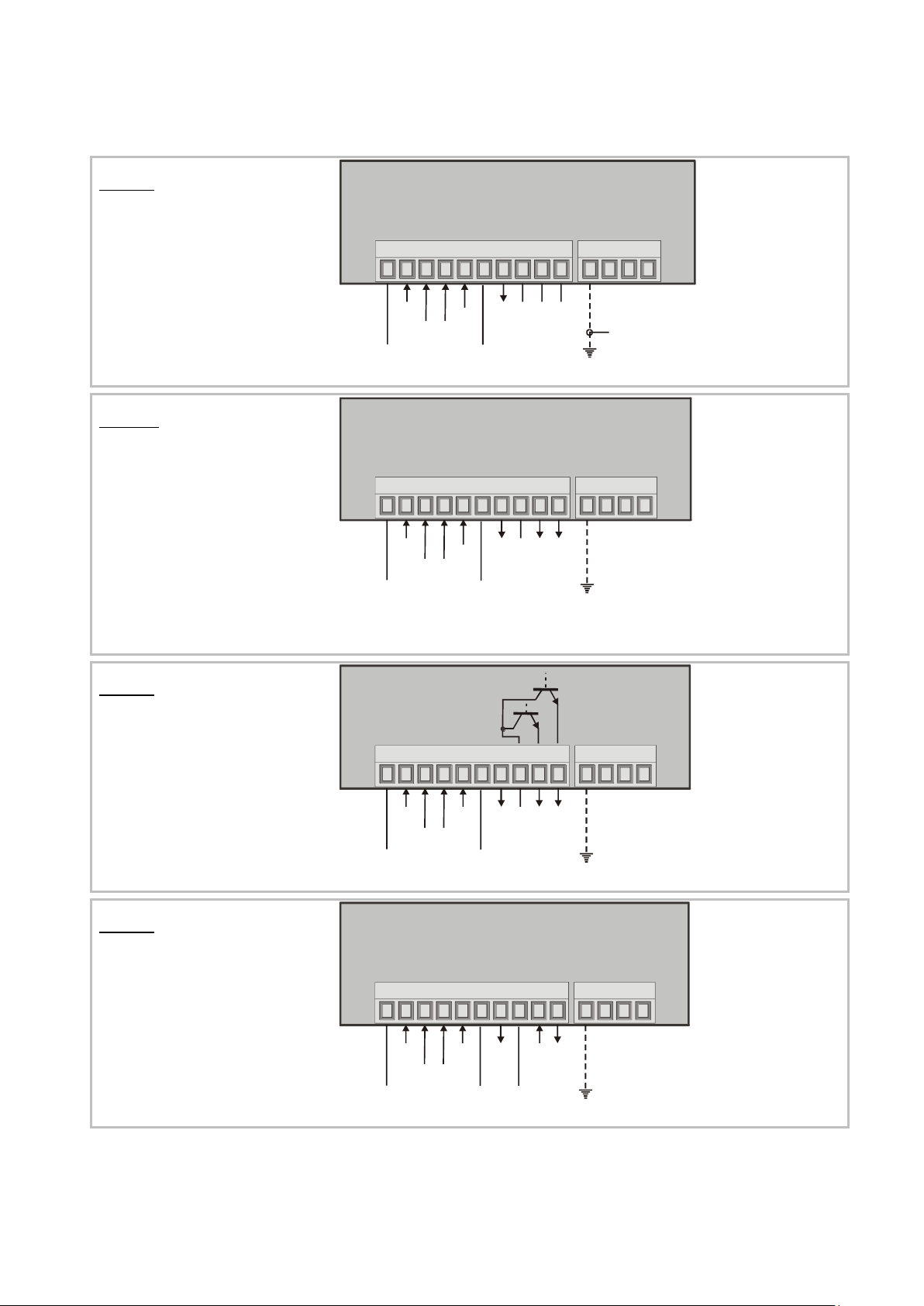
2. Electrical Connections
DX345:
Display unit only
Special versions with TTL inputs
(option TTLIN1) provide a +5V aux.
output on terminal 7, instead of +24V
Units with option SV006 provide
24 / 42 VAC power input instead of
115 / 230 VAC
GND
17-30VCD IN
1 2 3 4 5 6 7 8 9 10
INPUT A
INPUT B
RESET (C)
GND
+24VDC OUT
NC
PE
GND
230VAC
115 VAC
0 VAC
NC
NC
Only when you like
to tie internal GND
to earth potential
DX 346:
Display unit with
analog output
Special versions with TTL inputs
(option TTLIN1) provide a +5V aux.
output on terminal 7, instead of +24V
Units with option SV006 provide
24 / 42 VAC power input instead of
115 / 230 VAC
G
N
D
1
7
-
3
0
V
C
D
I
N
1 2 3 4 5 6 7 8 9 10
I
N
P
U
T
A
I
N
P
U
T
B
R
E
S
E
T
(
C
)
G
N
D
+
2
4
V
D
C
O
U
T
G
N
D
A
N
A
L
O
G
+
/
-
1
0
V
A
N
A
L
O
G
0
/
4
-
2
0
m
A
A
N
A
L
O
G
P
E
G
N
D
2
3
0
V
A
C
1
1
5
V
A
C
0
V
A
C
DX347:
Display unit with 2 presets
and transistor outputs
Special versions with TTL inputs
(option TTLIN1) provide a +5V aux.
output on terminal 7, instead of +24V
Units with option SV006 provide
24 / 42 VAC power input instead of
115 / 230 VAC
G
N
D
1
7
-
3
0
V
C
D
I
N
1 2 3 4 5 6 7 8 9 10
I
N
P
U
T
A
I
N
P
U
T
B
R
E
S
E
T
(
C
)
G
N
D
+
2
4
V
D
C
O
U
T
C
O
M
+
O
U
T
1
O
U
T
2
P
E
G
N
D
2
3
0
V
A
C
1
1
5
V
A
C
0
V
A
C
DX348:
Display unit with
serial interface
Special versions with TTL inputs
(option TTLIN1) provide a +5V aux.
output on terminal 7, instead of +24V
Units with option SV006 provide
24 / 42 VAC power input instead of
115 / 230 VAC
G
N
D
1
7
-
3
0
V
C
D
I
N
1 2 3 4 5 6 7 8 9 10
I
N
P
U
T
A
I
N
P
U
T
B
R
E
S
E
T
(
C
)
+
2
4
V
D
C
O
U
T
T
X
D
/
B
(
-
)
R
X
D
/
A
(
+
)
P
E
G
N
D
G
N
D
2
3
0
V
A
C
1
1
5
V
A
C
0
V
A
C
G
N
D
Dx34510b_oi_e.doc / Jun-15 Page 7 / 42
Page 8

When using this earthing option, please observe:
All terminals and potentials marked “GND“ will be earthed.
You should avoid multiple earthing, e.g. when you use a DC power supply where the
Minus is already connected to earth etc. Especially under poor earthing and grounding
conditions, multiple earth connections may cause serious EMC problems.
Independent of your setting, all functions of the unit are “active HIGH“ and the unit
triggers to positive transitions (rising edge).
With NPN setting please be aware that an open or unused RESET input is HIGH.
Therefore the unit will be kept in a continuous RESET state and will not work, unless you
tie the Reset line to GND (terminal 1 or 6)
Where your use 2-wire NAMUR type sensors, please select NPN, connect the negative
wire of the sensor to GND and the positive wire to the corresponding input.
2.1. Power Supply
The unit accepts DC supply from 17 V to 30 V when using terminals 1 and 2, and the consumption
depends on the level of the supply voltage (typically between 80 mA and 150 mA
plus current taken from aux. output).
For AC supply, terminals 0 VAC, 115 VAC or 230 VAC can be used. The total AC power
consumption is 7.5 VA.
Units with option "SV006" are prepared for AC supply with 24 VAC or 42 VAC and the screw
terminals are marked correspondingly.
The diagrams show a dotted line for grounding to PE. This connection is not necessary, neither for
safety nor for EMC. However, with specific applications, it can be useful to ground the common
potential of all signal lines.
2.2. Aux. Voltage Output
Terminal 7 provides an auxiliary output of 24 VDC / 120 mA max. for supply of sensors and
encoders. Units with TTL inputs (option TTLIN1) provide a 5 VDC / 120 mA auxiliary output on
terminal 7 instead.
2.3. Inputs A, B and Reset
In the basic setup menu these inputs can be configured to PNP (switch to +) or
to NPN (switch to -). This configuration is valid for all three inputs at a time.
The factory setting is always PNP.
With standard units the input level is always HTL (Low <2.0 V and High >9.0 V)
Units equipped with option TTLIN1 provide TTL / CMOS) level (Low <0.8 V and High >3.5 V)
Dx34510b_oi_e.doc / Jun-15 Page 8 / 42
Page 9
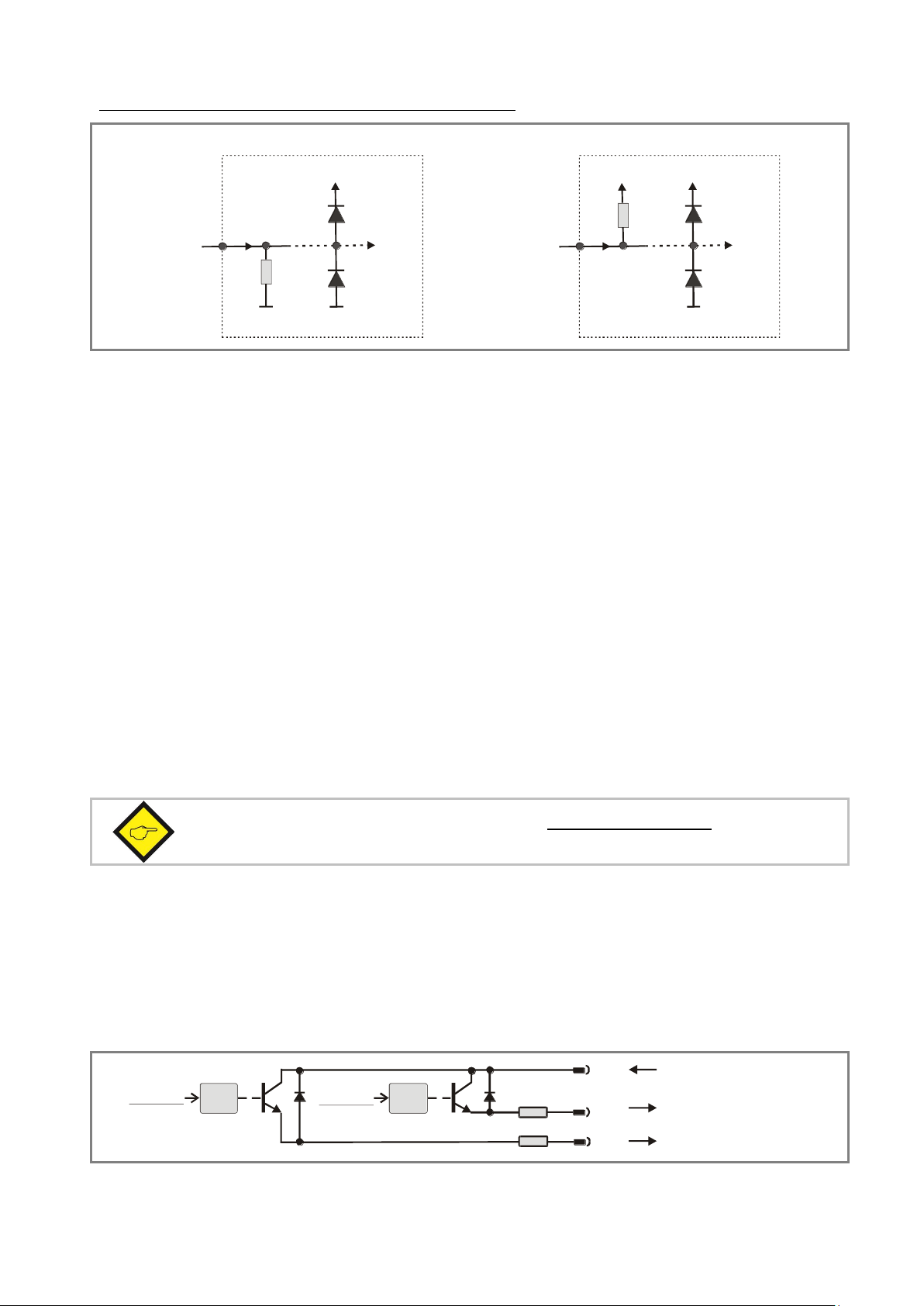
Typical input circuit (standard version with HTL inputs):
PNP
4,7k
GND GND
+24V int.
Input
4,7k
GND
Input
+24V int.
NPN
Important note: “Voltage out” and “Current out” cannot be used together.
Please do never connect mA and V simultaneously!
Opto Opto
33 R
(8)
(9)
(10)
Com+ (5 ... 35 V)
Output 1 (max. 150 mA)
Output 2 (max. 150 mA)
33 R
Preset 2
Preset 1
The counting inputs A and B are designed for input frequencies up to 100 kHz (with all counter
modes) and up to 25 kHz (with all other operating modes). The minimum pulse duration on the
Reset input must be 500 µsec. (maximum frequency 1 kHz). All inputs are designed to receive
impulses from an electronic impulse source. Where exceptionally you need to use mechanical
contacts, please connect an external capacitor between GND (-) and the corresponding input (+).
With a capacity of 10 µF, the maximum input frequency will reduce to 20 Hz and miscounting due
to contact bouncing will be eliminated.
2.4. Adjustable Analog Output (DX 346 only)
A voltage output is available, operating in a range of 0 ... +10 V or –10 V ... +10 V according to
setting. At the same time, a current output 0/4 … 20 mA is available. Both outputs refer to the
GND potential and the signal polarity changes with the sign in the display.
The outputs provide a 14 bits resolution and the response time to changes of the measuring value
is approx. 7 msec. (fin > 143 Hz). The maximum current of the voltage output is 2 mA, and the load
on the current output can vary between 0 and max. 270 ohms.
2.5. Optocoupler / Transistor Outputs (DX 347 only) *)
The outputs provide programmable switching characteristics and are potential-free. Please
connect terminal 8 (COM+) to the positive potential of the voltage you like to switch (range
5V....30V). You must not exceed the maximum output current of 150 mA. Where you switch
inductive loads, please provide filtering of the coil by means of an external diode.
*) For relay outputs please refer to model DX342
Dx34510b_oi_e.doc / Jun-15 Page 9 / 42
Page 10
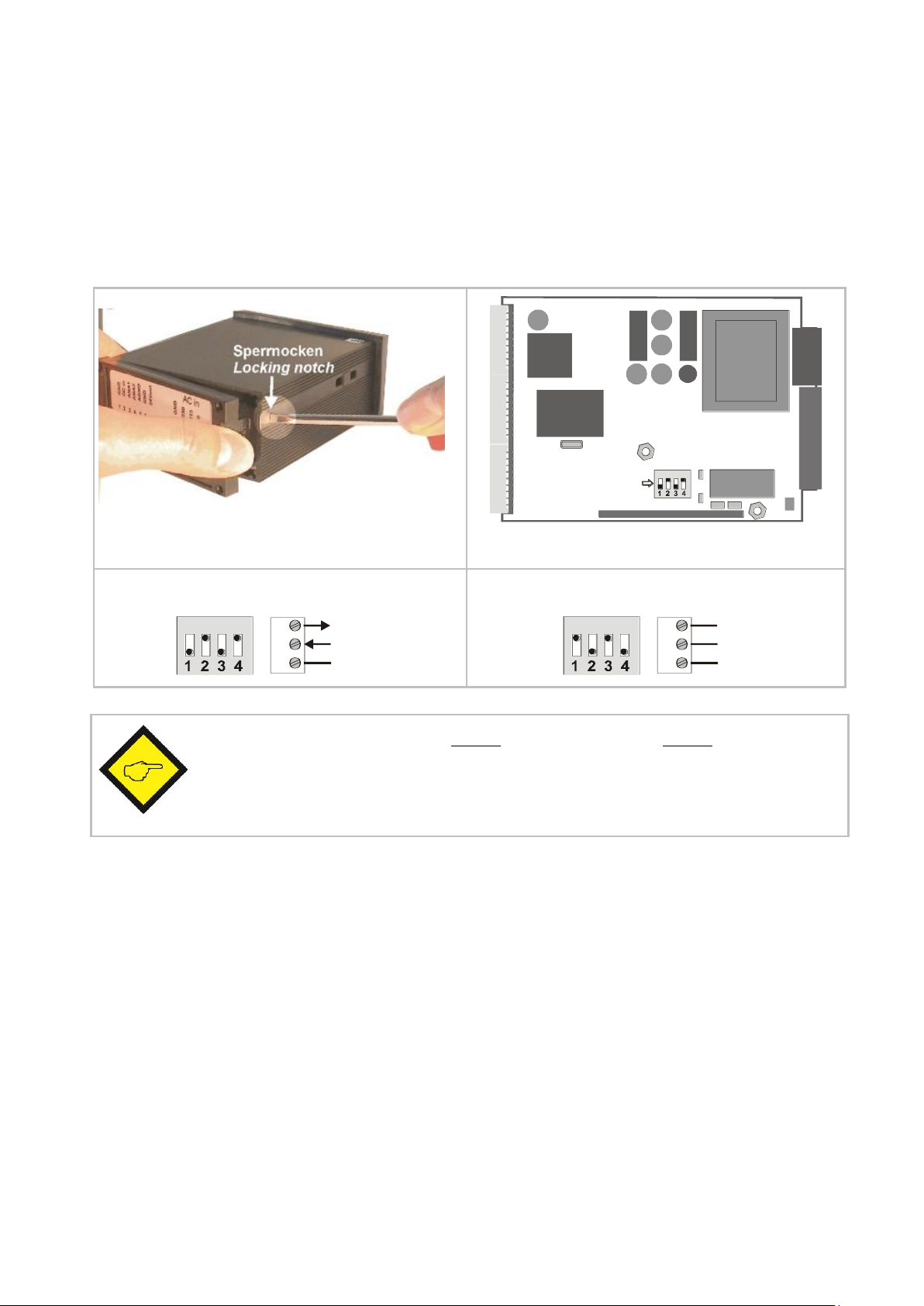
ON DIP
DIL-Switch
Removal of the back plane
Location of the DIL switch
RS232:
ON
8
9
10
RxD
TxD
GND
RS485:
ON
8
9
10
A (+)
B (-)
GND
Never set DIL switch positions 1 and 2 or DIL switch positions 3 and 4 to ON at
the same time!
After setting the switch, shift the print carefully back to the housing, in order to
avoid damage of the front pins for connection with the front plate.
2.6. Serial RS232 / RS485 interface (DX 348 only)
Ex-factory the unit is set to RS232 communication. This setting can be changed to RS485
(2-wire) by means of an internal DIL switch. To access the DIL switch, please remove the screw
terminal connectors and the backplane. Then pull the print to the rear to remove the PCB from the
housing.
Dx34510b_oi_e.doc / Jun-15 Page 10 / 42
Page 11
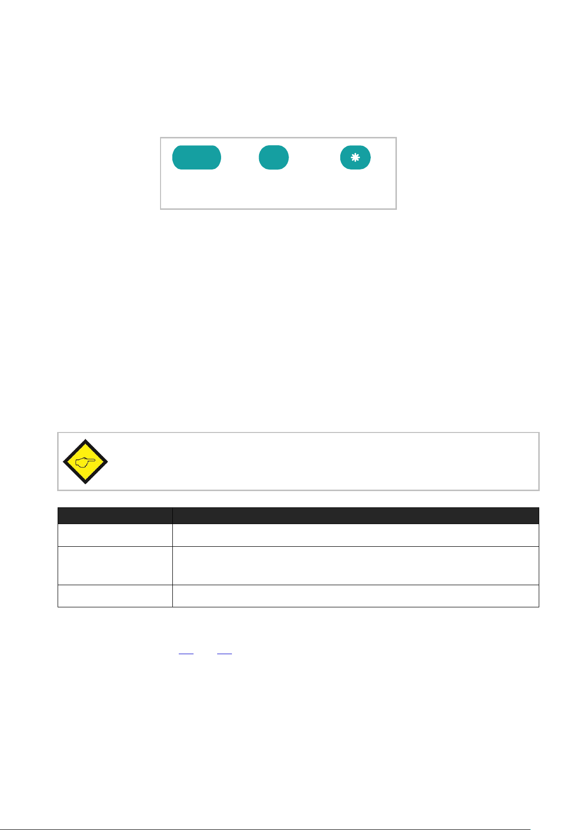
ENTER
(Input)
SET
(Setting)
Cmd
(Command)
You can only change over to other operation states while the unit is in display state.
Change over to
Key operation
Basic setup
Keep ENTER and SET down simultaneously for 3 seconds
Operational
parameter setup
Keep ENTER down for 3 seconds.
Teach operation
Keep Cmd down for 3 seconds
3. How to Operate the Front Keys
For setup and other operations the unit uses three front keys which subsequently will be
denominated as follows:
The functions of the keys are depending on the actual operating state of the unit.
The following three operating states apply:
Normal display state
Setup state
a.) Basic setup
b.) Operational parameter setup
Teach operation
3.1. Normal Display State
The Cmd key is only used to execute the Teach procedure with linearization. For more details
please refer to sections 5.1 and 5.2.
Dx34510b_oi_e.doc / Jun-15 Page 11 / 42
Page 12

3.2. Selection and Setting of Parameters
3.2.3. How to select a parameter
The ENTER key will scroll through the menu. The SET key allows to select the corresponding item
and to change the setting or the numeric value. After this, the selection can be stored by ENTER
again, which automatically changes over to the next menu item.
3.2.4. How to change parameter settings
With numerical entries, at first the lowest digit will blink. When keeping the SET key continuously
down, the highlighted digit will scroll in a continuous loop from 0 … 9 , 0 … 9. After releasing
the SET key, the actual value will remain and the next digit will be highlighted (blink). This
procedure allows setting of all digits to the desired values. After the most significant digit has
been set, the low order digit will blink again and you can do corrections if necessary.
With signed parameters, the high order digit will scroll from “0” to "9" (positive) followed by
“-“ and "-1" (negative)
3.2.5. How to store settings
To store the actual setting, press the ENTER key, which will also automatically scroll forward the
menu.
At any time the unit changes from programming mode to normal display operation, when you
keep the ENTER key down again for at least 3 seconds.
3.2.6. Time-Out Function
A “time-out” function will automatically conclude every menu level, when for a break period of 10
seconds no key has been touched. In this case, all changes which have not been confirmed by
ENTER yet would remain unconsidered.
Dx34510b_oi_e.doc / Jun-15 Page 12 / 42
Page 13
The Time-Out Function remains disabled during all Teach operations
Key
Function
ENTER will conclude or abort any Teach operation in progress
SET function is fully similar to normal set-up operation
Cmd will store the display value to the register and will change over to the next
interpolation point.
This action will reset all parameters to factory default values and your own
settings will be lost. You will have to repeat your individual setup procedure.
Factory default values are shown in the subsequent parameter tables.
3.3. Teach Operation
For details of the Teach procedure see section 5.2.
3.4. Set All Registers to “Default“
At any time you can return all settings to the factory default values.
To reset the unit to default values:
switch power off
press the ENTER key on the front
keep ENTER down while you power up again
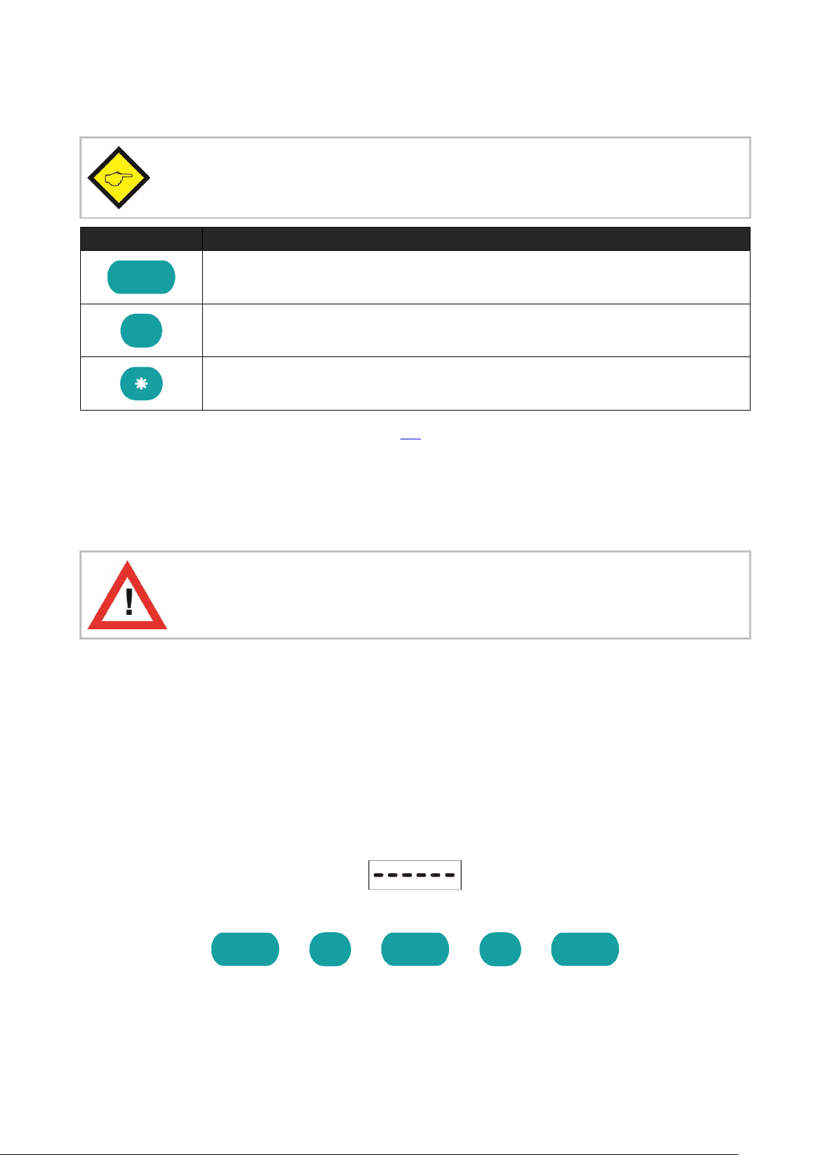
3.5. Code Locking of the Keypad
When the code locking of the keypad has been switched on, any key access first results in display
of
To access the menu you must press the key sequence
within 10 seconds, otherwise the unit will automatically return to the normal display mode.
Dx34510b_oi_e.doc / Jun-15 Page 13 / 42
Page 14

DX345
DX346
DX347
DX348
Type (Application Mode)
Type (Application Mode)
Type (Application Mode)
Type (Application Mode)
Input Characteristics
Input Characteristics
Input Characteristics
Input Characteristics
Brightness
Brightness
Brightness
Brightness
Code
Code
Code
Code
Linearization Mode *)
Linearization Mode *)
Linearization Mode *)
Linearization Mode *)
Analog Output Mode
Preselection Mode 1
Serial Unit Number
Analog Offset
Preselection Mode 2
Serial Format
Analog Gain
Hysteresis 1
Serial Baud Rate
Hysteresis 2
4. The Operator Menu
The menu provides one section with “Basic Parameters” and another section with “Operational
Parameters”. On the display you will only find those parameters which have been enabled by the
basic settings. E.g. when the Linearisation Function has been disabled in the basic set-up, the
associated linearization parameters will also not appear in the parameter menu.
All parameters, as good as possible, are designated by text fragments. Even though the
possibilities of forming texts are very limited with a 7-segment display, this method has proved to
be most suitable for simplification of the programming procedure.
The subsequent table shows the general structure of the menu.
Detailed descriptions of all parameters will follow in section 5.2.
4.1. Overview of Basic Parameters
*) Appears only with Modes "RPM" and "Count"
Dx34510b_oi_e.doc / Jun-15 Page 14 / 42
Page 15

Mode
"RPM"
(Tachometer)
Mode
"Time"
(Baking Time)
Mode
"Timer"
(Stopwatch)
Mode
"Count"
(Counter)
Mode
"Speed"
(Transition speed)
DX345
Frequency
Display Format
Base (Resolution)
Counter Mode
Time
Display Value
Frequency
Start/Stop
Scaling Factor
Display Value
Decimal Point
Decimal Value
Auto Reset
Set Value
Decimal Point
Wait Time
Wait Time
Latch Function
Reset/Set
Wait Time
Average Filter
Average Filer
Decimal Point
DX346
Frequency
Display Format
Base (Resolution)
Counter Mode
Time
Display Value
Frequency
Start/Stop
Scaling Factor
Display Value
Decimal Point
Decimal Value
Auto Reset
Set Value
Decimal Point
Wait Time
Wait Time
Latch Function
Reset/Set
Wait Time
Average Filter
Average Filer
Decimal Point
Analog Begin
Analog End
DX347
Preselection 1
Preselection 2
Frequency
Display Format
Base (Resolution)
Counter Mode
Time
Display Value
Frequency
Start/Stop
Scaling Factor
Display Value
Decimal Point
Decimal Value
Auto Reset
Set Value
Decimal Point
Wait Time
Wait Time
Latch Function
Reset/Set
Wait Time
Average Filter
Average Filer
Decimal Point
DX348
Frequency
Display Format
Base (Resolution)
Counter Mode
Time
Display Value
Frequency
Start/Stop
Scaling Factor
Display Value
Decimal Point
Decimal Value
Auto Reset
Set Value
Decimal Point
Wait Time
Wait Time
Latch Function
Reset/Set
Wait Time
Average Filter
Average Filer
Decimal Point
Serial Timer
Serial Mode
Serial Code
All
units
P01_H(*)
P01_H(*)
P01_Y(*)
P01_Y(*)
..
..
P16_H(*)
P16_H(*)
P16_Y(*)
P16_Y(*)
4.2. Overview of Operational Parameters
*) Appears only with modes "RPM" and "Count" when the linearization function has been enabled
Dx34510b_oi_e.doc / Jun-15 Page 15 / 42
Page 16

To access the Basic Setup press ENTER and SET simultaneously for at least 3 seconds.
Menu
Setting Range
Default
Operation Mode:
Tachometer, frequency meter (5.2.1)
Baking time / processing time indicator (5.2.2)
Timer, Stopwatch (5.2.3)
Counter for position or event (5.2.4)
Speed calculation from
differential transition time (5.2.5)
Switching characteristics of the inputs:
NPN, switch to “-“
PNP, switch to “+“
Brightness of the LED display:
20%, 40%, 60%,
80%, 100%
100%
5. Setup Procedure
For better understanding the following sections 4.1 and 4.2 explain settings related to the display
only. Model-specific settings for Analog Output, Preselection’s and Serial Link will be explained
separately under sections 5.3 to 5.5, later.
5.1. Basic Settings
These settings in general have to be carried out one time only upon the very first use of the unit.
The basic setup selects the desired operation mode of the unit, the input characteristics
PNP/NPN and the desired brightness of the LED display.
Dx34510b_oi_e.doc / Jun-15 Page 16 / 42
Page 17

Continuation “Basic Settings”
Menu
Setting Range
Default
Keypad protection code:
(see section 3.5)
Keypad enabled continuously
Keypad locked for any access
Keypad locked, except for access to
preselection’s Pres 1 und Pres 2 (DX 347 only)
Linearization Mode: *)
For details please refer to 5.1 and 5.2
The linearization is switch off.
Linearization settings for the positive range only
(negative values will appear as a mirror).
Linearization over the full numeric range
*) with Tachometer mode and Counter mode only
Dx34510b_oi_e.doc / Jun-15 Page 17 / 42
Page 18

Menu
Range (OS)*
Default
Frequency:
Set a typical operating frequency for your application.
1 Hz to
25 000 Hz
1000
Display Value:
Set the value you would like to see on your display with
above frequency at the input.
1 ... 99999
1000
Decimal Point:
Select the desired position like shown in the display.
000.000
no decimal point
000000
decimal point at position 1
00000.0
---->
decimal point at position 5
0.00000
Wait Time:
Define a “waiting time“, this is the time in seconds that
the unit will wait from one input pulse to the next,
before it sets the display to zero. When you enter “0“,
the unit will wait forever and show the last result until
it receives the next input.
0.1 … 99.9 sec
1.0
The setting of this parameter automatically limits the minimum input
frequency correspondingly. With “Wait” set to e.g. 0.1 sec. the unit will
respond to frequencies > 10 Hz only and all lower frequencies will just
display 0.
Average Filter:
Selectable average filter to suppress unstable display
with unsteady input frequencies.
No filtering
2, 4, 8, 16 = number of floating average cycles.
Model DX346 also provides a signed speed display with the +/- sign changing according to
the direction of rotation. To indicate the direction in the display by a sign, +/- 10 V must be
adjusted in the analog menu (see section 5.3).
(0)
(1)
5.2. Operational Parameters
5.2.1. RPM, operation as tachometer or frequency counter
(Input A = active input, Input B not in use), (only DX346: Input B = active input)
*) OS only with DX348
Dx34510b_oi_e.doc / Jun-15 Page 18 / 42
Page 19

Menu
Range (OS)*
Default
Display Format:
Select between seconds, minutes, minutes and seconds
or minutes with two decimal positions. This will also
automatically set your decimal point to the proper
place.
Seconds
Minutes
Minutes and seconds
Minutes with two decimal positions
Frequency:
Set a typical operating frequency for your application.
1 Hz to
25 000 Hz
100
Display Value:
Set the value you would like to see on your display with
above frequency at the input.
1 ... 999999
100
Wait Time:
Define a “waiting time“, this is the time in seconds that
the unit will wait from one input pulse to the next,
before it sets the display to zero. When you enter “0“,
the unit will wait forever and show the last result until
it receives the next input.
0.1 … 99.9 s
5.0
The setting of this parameter automatically limits the minimum input
frequency correspondingly. With “Wait” set to e.g. 0.1 sec. the unit will
respond to frequencies > 10 Hz only and all lower frequencies will just
display 0.
Average Filter
Selectable averages filter to suppress unstable display
with unsteady input frequencies.
No filtering
2, 4, 8, 16 = number of floating average cycles.
(0)
(1)
(2)
(3)
(0)
(1)
5.2.2. Time, display of baking or processing time (reciprocal speed)
(Input A = frequency input, Input B not in use)
*) OS only with DX348
Dx34510b_oi_e.doc / Jun-15 Page 19 / 42
Page 20

Menu
Range (OS)*
Default
Time base / Resolution of the timer:
Milliseconds
1/100 seconds
1/10 seconds
Integer seconds
Minutes with two decimal positions
Minutes with one decimal position
Hours : minutes : seconds
Start/Stop of time measurement:
Time count is active while input A is HIGH.
Rising edge on input A starts count.
Rising edge on input B stops count.
Period time measurement.
Repeating display of the time between two rising edges
on input A
Time count is active while input A is LOW.
Auto Reset:
Time count cumulates with every new start. No
automatic Reset. Use the Reset input to set to zero.
Every start initializes a new count starting from zero.
Latch Function:
Real time display, count visible.
Frozen display of the final count result after every Stop.
The timer counts in the background,
(0)
(1)
(2)
(3)
(4)
(5)
(6)
(0)
(1)
(2)
(0)
(1)
(0)
(1)
5.2.3. Timer, Stopwatch
Please note that open NPN inputs are always “HIGH“ and open PNP inputs are always “LOW“.
*) OS only with DX348
Dx34510b_oi_e.doc / Jun-15 Page 20 / 42
Page 21

5.2.4. Count, Counter mode
Menu
Range (OS)*
Default
Counting Mode:
Input A counts and input B selects the
counting direction
(LOW = increment, HIGH = decrement)
Summing counter, A + B
Differential counter, A – B
Quadrature up/down counter A/B with single
edge count (x1)
Quadrature up/down counter A/B with double
edge count (x2)
Quadrature up/down counter A/B with (x4) edge count.
Impulse Scaling Factor:
Example: setting 1.2345 results in display of
12 345 after 10 000 input pulses.
0.0001
…
9.9999
1.0000
Set Value:
Every Reset signal will set the display to the value
entered here
–199 999
...
999 999
0
Reset/Set Enable:
No setting or resetting of the counter is possible
Set / Reset by the front SET key
Set / Reset by remote signal to the Reset input.
Set / Reset by front SET key and by external input.
Decimal Point:
Select the desired position like shown in the display.
000.000
no decimal point
000000
one decimal position
00000.0
---->
five decimal positions
0.00000
The counting range of the unit is limited from -199999 to 999999.
In case of underflow or overflow the unit will display
The counter stores all counting data also in power-down state
(EEProm with data retention >10 years)
With the summing mode (A+B) and the differential mode (A-B) please note
that the impulse scaling factor will only affect input A
(0)
(1)
(2)
(3)
(4)
(5)
(0)
(1)
(2)
(3)
*) OS only with DX348
Dx34510b_oi_e.doc / Jun-15 Page 21 / 42
Page 22

Menu
Setting Range
Default
Time:
Enter a typical delay time which you expect between
the start and stop signals.
000.001
…
999.999 sec
1.000 sec
Display Value:
Enter the speed you would like to see in the display
when an object passes within above time.
000.001
…
999.999
1.000
Decimal Point:
Select the desired position like shown in the display.
000.000
no decimal point
000000
done decimal position
00000.0
---->
five decimal positions
0.00000
Wait Time
How long should the last result remain in the display
before it returns to zero? Set the desired waiting time.
With setting “0” the display will freeze and wait until to
the next measuring cycle.
0.00
...
9.99
1.00
Menu
Setting Range
Default
P01_X
Linearization point 1:
X value of the first interpolation point.
-199999
... 999999
999999
P01_Y
Linearization point 1:
Y value of the first interpolation point.
-199999
... 999999
999999
…
…
P16_X
Linearization point 16:
X value of the 16. interpolation point.
-199999
... 999999
999999
P16_Y
Linearization point 16:
Y value of the 16. interpolation point.
-199999
... 999999
999999
5.2.5. Speed from differential time between a Start and a Stop input
Input A operates as a start input and input B operates as a Stop input. The differential time
between start and stop will be converted into the speed of the passing object.
5.2.6. Linearization points
The linearization points will only appear with Operation Modes "RPM" or "Count" when
Linearization is enabled.
For more details about linearization please refer to section 6.1
Dx34510b_oi_e.doc / Jun-15 Page 22 / 42
Page 23

Menu
Range (OS)**
Default
Analog Characteristics:
Select one of the following options:
+/-10 V (bipolar)
0-10 V (positive output only)
4-20 mA current output.
0-20 mA current output
Where you set the output to +/-10 Volts, your input
signals A/B must be of quadrature type with phase
displacement. The polarity of the output follows the
sign in the display (operation as a counter or as a
speed display with detection of direction of rotation)
Analog Offset *):
Set this register to “0” when your output range should
begin at zero (or 4 mA) If you desire another initial
output value, set this register correspondingly. Setting
5.000 means your output will start at 5 Volts instead of
zero.
-9.999 ... +9.999
0.000
Analog Gain *):
Set the analog stroke you desire: Setting 1000 means
10 Volts or 20 mA. Setting 200 reduces the stroke to 2
Volts or 4 mA.
00.00 ... 99.99
10.00
Operation mode
Response time analog output
Tachometer, frequency meter (5.2.1)
330ms at f >3Hz
1/f at f < 3Hz
Baking time / processing time indicator (5.2.1)
330ms at f >3Hz
1/f at f < 3Hz
Timer, Stopwatch (5.2.3)
7 ms
(With latch function after every measurement)
Counter for position or event (5.2.4)
Counter value + 7ms
Speed calculation from
differential transition time (5.2.5)
Runtime + 7ms
(0)
(1)
(2)
(3)
5.3. Model DX 346: Additional Settings for the Analog Output
The Basic Menu provides the following additional settings:
*) see also next page
**) OS only with DX348
Response time of the analog output:
The analog output behaves like the display output.
Dx34510b_oi_e.doc / Jun-15 Page 23 / 42
Page 24

Menu
Setting Range
Default
Analog-Begin:
Start value of the analog output.
-199999 ... 999999
0
Analog-End:
End value of the analog output.
-199999 ... 999999
10000
2
4
6
8
10
1000 2000 3000 4000 5000
Display Value
Volts
Analogue Output
A-ChAr = 0 - 10 V
AnAbEG = 1400
OFFSEt = 2.000
AnAEnd = 2200
GAin = 8.00
All settings refer to the scaled values which are shown in the display of the unit.
The following Operational Parameters provide scaling of the analog output:
By means of these two parameters any window of the whole display range can be mapped onto
the analog output.
The subsequent example shows how to convert the display range from 1400 to 2200 into an
analog signal of 2 - 10 volts.
Dx34510b_oi_e.doc / Jun-15 Page 24 / 42
Page 25

5.4. Model DX 347: Additional settings for Preselection’s
Menu
Range (OS)****
Default
Switching characteristics of output 1.
(0)
Greater/Equal: output to switch statically ”ON”
when display value ≥ preset value.
(1)
Lower/Equal: output to switch statically ”ON”
when display value ≤ preset value.
(2)
Greater/Equal: output to switch dynamically ”ON”
when display value ≥ preset value.
(timed pulse output *)
(3)
Lower/Equal: output to switch dynamically ”ON”
when display value ≤ preset value.
(timed pulse output *)
(4)
Reset: Timed impulse output *) and automatic Reset
to zero when the display value reaches Preset 1.
(5)
Set:: Timed impulse output *) and automatic setting
to preset 1 when the display value reaches zero.
Switching characteristics of output 2.
(0)
See Char 1
(1)
See Char 1
(2)
See Char 1
(3)
See Char 1
(4)
Output switches statically ON when
display value ≥ Preset 1 – Preset 2 **).
(5)
Output switches dynamically ON when
display value ≥ Preset 1 – Preset 2 **).
HYSt 1
Hysteresis 1: Adjustable hysteresis for output 1. ***)
Setting range 0 ... 99999 display units
0
HYSt 2
Hysteresis 2: Adjustable hysteresis for output 2, ***)
Setting range 0 ... 99999 display units
0
The basic setup menu provides the following additional parameters:
*) Fixed pulse duration of 500 msec (factory adjustable only)
**) This feature serves for generation of an anticipation signal with a fixed distance to the
preset 1 signal. The anticipation automatically follows the setting of preset 1 (trailing preset).
***) Switching hysteresis is only active with "RPM" and "Time" operation
****) OS only with DX348
Dx34510b_oi_e.doc / Jun-15 Page 25 / 42
Page 26

The following operational parameters provide setting of the switching points:
Menu
Setting Range
Default
Preselection 1:
-199999...
999999
10000
Preselection 2:
-199999...
999999
5000
Preselection
Hysteresis
GE=Greater/Equal
Display Value
Hysteresis effect with "Greater / Equal"
Preselection
LE=Lower/Equal
Hysteresis
Display Value
Hysteresis effect with "Lower / Equal"
Display
Meaning
Both outputs are actually off.
Both outputs are actually on.
Output 1 is on.
Output 2 is off.
Output 1 is off.
Output 2 is on.
The working direction of the Hysteresis depends on the setting of the switching characteristics.
With settings „GE“ or „LE“ respectively, the following switch points will result:
It is possible to check up on the actual switching state of the outputs at any time.
For this, just tap on the ENTER key shortly.
The display will then show for the next two seconds one of the following information:
Dx34510b_oi_e.doc / Jun-15 Page 26 / 42
Page 27

Menu
Range (OS)*
Default
Serial Unit Number:
You can assign any address number between 11 and
99 to your unit.
The address must not contain a “0“ because these
numbers are reserved for collective addressing.
0 ... 99
11
Serial data format:
The first character indicates the number of Data Bits.
The second character specifies the Parity Bit
(“even” or “odd” or “none”)
The third character indicates the number of Stop Bits.
Baud Rate:
The adjoining Baud rates can be selected
(0)
(1)
(2)
(3)
(4)
(5)
(6)
(7)
(8)
(9)
(0)
(1)
(2)
(3)
(4)
(5)
(6)
5.5. Model DX 348: Additional Settings for the Serial Interface
The basic setup menu contains the main parameters for configuration of the serial interface
*) OS only with DX348
Dx34510b_oi_e.doc / Jun-15 Page 27 / 42
Page 28

The following operational parameters provide setting of the communication profile:
Menu
Range (OS)*
Default
Serial Timer:
Setting 0,000 allows manual activation of a serial data
transmission at any time. All other settings specify the
cycle time for automatic transmission (provided the Serial
Mode is set to "Printer")
0.000;
0.010…
9..999 sec
0.1 sec
Between two transmission cycles the unit will allow a
pause depending on the baud rate. The minimum cycle
times for timer transmissions are shown in the table.
Baud Rate
Minimum Cycle Time [msec]
600
384
1200
192
2400
96
4800
48
9600
24
19200
12
38400
6
Serial Mode:
Operation according to communication profile (see 5.5.1)
Transmission of string type 1 (see 5.5.2)
Transmission of string type 2 (see 5.5.2)
Serial Register-Code:
Specifies the register code of the data to be transmitted.
The most important register codes are the actual display
value and the serial Set/Reset command code
Register
S-Code
ASCII
Actual display value
101
: 1
Activate SET /RESET
60
6 0
100
...
120
101
(0)
(1)
(2)
*) OS only with DX348
Dx34510b_oi_e.doc / Jun-15 Page 28 / 42
Page 29

This is the general format of a serial
request string :
EOT
AD1
AD2
C1
C2
ENQ
EOT = Control character (Hex 04)
AD1 = Unit address, High Byte
AD2 = Unit address, Low Byte
C1 = Register code, High Byte
C2 = Register code, Low Byte
ENQ = Control character (Hex 05)
ASCII-Code:
EOT 1 1 : 1
ENQ
Hexadecimal:
04
31
31
3A
31
05
Binary:
0000 0100
0011 0001
0011 0001
0011 1010
0011 0001
0000 0101
Upon correct request the unit will respond
as shown on the right. Leading zeros will
be suppressed.
BCC represents a block check character
generated from an Exclusive-OR of all
characters from C1 through ETX
(inclusively)
STX
C1
C2
x x x x x x x
ETX
BCC
STX = Control character (Hex 02)
C1 = Register code, High Byte
C2 = Register code, Low Byte
x x x x x = Register data
ETX = Control character (Hex 03)
BCC = Block check character
ASCII
STX : 1 - 1 8 0
ETX
BCC
Hex
02
3A
31
2D
31
38
30
03
1C
Binary
0000
0010
0011
1010
0011
0001
0010
1101
0011
0001
0011
1000
0011
0000
0000
0011
0001
1100
5.5.1. PC-Mode
Communication with PC - Mode allows free readout of all parameters and registers of the unit.
The subsequent example shows the details of communication for serial readout of the actual
display value.
Example: Request for the actual display value from unit number 11:
With incorrect request strings, the unit only responds STX C1 C2 EOT or just NAK.
Provided the actual display value of the unit would be "-180" (example), the full response of the
unit would be as shown below:
Again BCC represents the block check character formed from the Exclusive-OR of all characters
from C1 through ETX
Dx34510b_oi_e.doc / Jun-15 Page 29 / 42
Page 30

ASCII
EOT
AD1
AD2
STX
C1
C2
Data
ETX
BCC
Hex
04
31
31
02
36
30
31
03
34
Binary
0000
0100
0011
0001
0011
0001
0000
0010
0011
0110
0011
0000
0011
0001
0000
0011
0011
0100
ASCII
EOT
AD1
AD2
STX
C1
C2
Data
ETX
BCC
Hex
04
31
31
02
36
30
30
03
35
Binary
0000
0100
0011
0001
0011
0001
0000
0010
0011
0110
0011
0000
0011
0000
0000
0011
0011
0101
Units with serial link also allow setting or resetting the counter by serial command (similar to the
external input or front key function). To activate the Reset command, please write “1” to register
code “60”. To release the Reset command again, write “0” to the same register.
The following strings show how to set or reset a unit with unit No. 11:
Reset ON :
Reset OFF :
For more details about serial communication please refer to the separate document "SERPRO"
Dx34510b_oi_e.doc / Jun-15 Page 30 / 42
Page 31

„S-mod“
Transmission String Type
„Print1“
Space
Sign
Data
Line
feed
Carriage
return
+/-
X X X X X X LF
CR
„Print2“
Sign
Data
Carriage
return
+/-
X X X X X X CR
Cyclic (timed)
transmissions:
Set the Serial Timer to any value ≥ 0.010 sec.
Select the desired string type by parameter "S-mod"
After exit from the menu the timed transmissions will
start automatically
Manual activation of
transmissions
Set the Serial Timer to 0.000.
Select the desired string type by parameter "S-mod"
After exit from the menu a transmission can be activated at any time by
shortly pressing the ENTER key
5.5.2. Printer-Mode
The Printer Mode allows cyclic or manual activation of transmissions of the specified register
data. The corresponding register can be specified by means of parameter „S-Code“.
Another parameter named „S-mod“ allows selection between two different string types:
The mode of activation of serial transmissions can be determined as follows:
Dx34510b_oi_e.doc / Jun-15 Page 31 / 42
Page 32

With respect to the consistency of the linearization, the x- registers have to use continuously
increasing values, e.g. the x- registers must conform to the constraint
P01_X < P02_X < … < P15_X < P16_X.
Independent of the selected linearization mode, the possible setting range of all registers
P01_x, P01_y,…, P16_x, P16_y is always -199999 … 999999
With measuring values lower than P01_x the display will always be P01_y
With measuring values higher than P16_x, the display will always be P16_y.
x
y
P1(x)= 0
P1(y)= 0
Linearization Mode = 1_quA
x
y
Linearization Mode = 4_quA
P1(x)= -1000
P1(y)= 900
P8(x)= 0
P8(y)= 750
P16(x)= +1000
P16(y)= - 600
*)
P16(x)= 1000
P16(y)= 800
*) Mirror of positive range
6. Special Functions
6.1. Linearization
This function allows converting a non-linear input signal into a linear presentation or vice-versa.
There are 16 interpolation points available, which can be freely arranged over the whole
measuring range in any distance. Between two points the unit automatically will interpolate
straight lines.
It is advisable to set many points into areas with strong bending, and to use only a few points in
areas with little bending. „Linearisation Mode“ has to be set to either „1-quA“ or „4-quA“ to
enable the linearization function (see subsequent drawing).
Parameters P01_x to P16_x select 16 x- coordinates, representing the display values which the
unit would normally show in the display. With parameters P01_y to P16_y you can specify, which
values you would like to display instead of the corresponding _x values.
This means e.g. that the unit will replace the previous P02_x value by the new P02_y value.
Dx34510b_oi_e.doc / Jun-15 Page 32 / 42
Page 33

Application Example:
d
φ
(1-cos )
φ
Incremental Encoder
d = d0
Display value
P01_x
P05_x
P16_x
P01_y
P05_y
P16_y
P03_x
P03_y
P07_y
P07_x
Encoder Position ( )φ
Display (d)
P15_y
P15_x
The picture below shows a Watergate where the opening is picked up by means of an
incremental encoder. We would like to display the clearance of the gate "d", but the existing
encoder information is proportional to the angular information φ.
Dx34510b_oi_e.doc / Jun-15 Page 33 / 42
Page 34

During manual input of interpolation points the unit will not examine the settings
P01_x to P16_x. Therefore the operator is responsible for observation of the constraint
P01_X < P02_X < … < P15_X < P16_X.
6.2. Manual Input or „Teaching“ of the Interpolation Points
Interpolation points to form the linearization curve can be entered one after each other, using the
same procedure as for all other numeric parameters. This means you will have to enter all
parameters P01_x to P16_x and P01_y to P16_y manually by keypad.
In most cases it should however be much more convenient to use the Teach function.
For this method we have to move the encoder, step by step, from one interpolation point to the
next. Every time we enter the desired display value by keypad.
How to use the Teach Function:
Please select the desired range of linearization (see 5.1).
Hold down the “Cmd” key for 3 seconds, until the display shows “tEACh”. Now the unit
has switched over to the Teach mode. To start the teach procedure please press again
“Cmd” within the next 10 seconds. The display will then show “P01_X”.
With respect to the consistency required for linearization, all parameters from P01_X to
P16_Y will first be overwritten by suitable initial values. Initial values for „P01_X“ and
„P01_Y“ are -199999 and all other values will start with 999999.
Press once more “Cmd” to display the actual encoder position. Then move the encoder to
the first of the desired interpolation points
When you read the x-value of your first interpolation point in the display, press “Cmd”
again. This will automatically store the actual display value to the P01_x register. For
about 1 second you will read “P01_y “ on the display, followed by the same reading again
that has been stored previously
This display value now can be edited like a regular parameter, and you can change it to
the desired P01_y value
When you read the desired P01_y value in your display, store it by pressing “Cmd” again.
This will automatically cycle the display to the next interpolation point P02_x.
Once we have reached and stored the last interpolation points P16_x/y, the routine will
restart with P01_x again. You are free to double-check your settings once more or to make
corrections.
To conclude the Teach procedure, keep ENTER down for about 2 seconds. In the display
you will read “StOP” for a short time, and then the unit returns to the normal operation. At
the same time all linearization points have been finally stored.
Dx34510b_oi_e.doc / Jun-15 Page 34 / 42
Page 35

The unit will examine the constraint valid for the x-values of interpolation points. Every
interpolation point must be higher than its preceding point. Where this constraint is
breached, all 6 decimal points will blink automatically as a warning. Pressing the CMD key
will not store the illegal value, but result in an error text "E.r.r.-.L.O."
To exit the teach mode again, you have the following two possibilities:
1. Press the enter key for 2 seconds. On the display you will read “StOP” for a short time,
and then the unit will switch back to the normal mode.
2. Just do nothing. After 10 seconds the unit will switch back to the normal mode
automatically.
In both cases the parameters of linearization P01_X to P16_Y will not change.
Dx34510b_oi_e.doc / Jun-15 Page 35 / 42
Page 36

96,0 (3.780’’)
110,0 (4.331’’)
44,0 (1.732)
10,0
(.394)
8,0
(.315)
91,0 (3.583)
9,0 (.345)
129,0 (5.079)
140,5 (5.531)
48,0 (1.890)
7. Technical Appendix
7.1. Dimensions
Panel cut out: 91 x 44 mm (3.583 x 1.732’’)
Dx34510b_oi_e.doc / Jun-15 Page 36 / 42
Page 37

7.2. Technical Specifications
Power supply:
Input voltage(AC):
Power consumption:
Input voltage (DC):
Protection circuit (DC):
Ripple (DC):
Consumption:
Connections:
115 / 230 VAC (+/- 12.5 %)
7.5 VA
24 VDC (17 … 30 VDC)
reverse polarity protection
≤ 10 % at 24 VDC
100 mA at 24 VDC / 80 … 150 mA at 17… 30 VDC
(with an unloaded encoder supply)
AC: screw terminal, 2.5 mm², DC: screw terminal, 1.5 mm²
Encoder supply:
Output voltage:
Output current:
24 VDC +/- 15 % (with AC supply)
5 VDC (with option TTLIN1)
max. 150 mA (with AC and DC supply)
Incremental inputs:
Number of inputs:
Signal levels:
Channels:
Frequency:
Consumption:
Connections:
3 x PNP/NPN/Namur
HTL (standard): LOW 0 … 3.5 V, HIGH 9 … 30 V
TTL (option TTLIN1): CMOS, LOW 0 …0.8 V, HIGH 3.6 … 5 V
A, B (pulses) und C (reset signal),
max. 100 kHz (counter mode)
max. 25 kHz (all other modes)
reset input C: 1 kHz (pulse time min. 500 µs)
5.1 mA at 24 V (Ri ≈ 4.7 kOhm)
screw terminal, 1.5 mm²
Accuracy:
Frequency measurement:
+/- 100 ppm +/- 1 digit
Refreshment time:
Display:
approx. 7 ms (tachometer mode 330 ms)
Analog output
(DX346):
Volt output:
mA output:
Resolution:
Accuracy:
Reaction time:
+/- 10 V, max. 2 mA
0 … 20 mA / 4 … 20 mA (burden: max. 270 Ohm)
14 Bit + sign
0.1 %
depends on selected operation mode
Transistor outputs
(DX347):
Number of outputs:
Signal level:
Output current:
Connections:
2 x PNP
5 … max. 35 V
max. 150 mA
screw terminal, 1.5 mm²
Serial interface
(DX348):
Format:
Baud rates (selectable):
Operation modes:
Connections:
RS232, switchable to RS485 (2-conductors)
600, 1200, 2400, 4800, 9600, 19200, 38400 Baud
PC or printer mode
screw terminal, 1.5 mm²
Display:
Type:
Characteristic:
6 Digit LED display
high-efficiency orange, 15 mm / 0.59’’
Housing:
Type:
Material:
Mounting:
Dimensions:
Protection class:
Weight:
Norly UL94 – V-0
plastic
panel
cut out (w x h): 91 x 44 mm / 3.583 x 1.7323 inch
outer dimensions (w x h x d):
110 x 48 x 140 mm / 4.331 x 1.889 x 5.511 inch
front: IP 65 / rear: IP20
approx. 450 g
Ambient temperature:
Operation:
Storage:
0 °C … +45 °C / +32 … +113 °F (not condensing)
-25 °C … +70 °C / -13 … +158 °F (not condensing)
Failure rate:
MTBF in years
DX345: 96.6 a, DX346: 79.6 a, DX347: 84.3 a, DX348: 89.0 a
(long-term usage at 60 °C / 140 °F ):
Conformity & standards:
EMC 2004/108/EC:
LV 2006/95/EC
Guideline 2011/65/EU:
EN 61000-6-2, EN 61000-6-3, EN 61000-6-4
EN 61010-1
RoHS-conform
Dx34510b_oi_e.doc / Jun-15 Page 37 / 42
Page 38

Description
Text
Min. Value
Max. Value
Default Value
Positions.
Characters
Serial Code
Unit Type
tYPE 0 4 0 1 0 00
Characteristic
CHAr 0 1 1 1 0 01
Brightness
briGht 0 4 0 1 0 02
Code
CodE 0 2 0 1 0 03
Frequency (Hz)
FrEqu 1 25000
1000
5 0 04
Display Value
diSPL 1 99999
1000
5 0 05
Decimal point
dPoint 0 5 3 1 0 06
Wait Time (sec)
L(Ait 1 999
10 3 1
07
Average Filter
FiLtEr 0 4 0 1 0 08
Display Format
diSFor 0 3 0 1 0 09
Frequency (Hz)
FrEqu 1 25000
100 5 0
10
Display Value
diSPL 1 999999
100 6 0
11
Wait Time (sec)
L(Ait 1 999
50 3 1
12
Average Filter
FiLtEr 0 4 0 1 0 13
Base
bASE 0 6 0 1 0 14
Start / Stop
StArt 0 3 1 1 0 15
Auto Reset
rESEt 0 1 0 1 0 16
Latch Function
LAtcH 0 1 0 1 0 17
Count Mode
n)odE 0 5 3 1 0 18
Factor
FActor 1 99999
10000
5 4 19
Set Value
SEt
-199999
999999
0
86 0 20
Reset / Set
rESEt 0 3 3 1 0 21
Decimal point
dPoint 0 5 0 1 0 22
Measuring Time (sec)
tin)E 1 999999
1000
6 3 23
Display Value
diSPL 1 999999
1000
6 0 24
Decimal point
dPoint 0 5 0 1 0 25
Wait Time (s)
L(Ait 0 999
100 3 1
26
7.3. Parameter-List
7.3.3. General
Dx34510b_oi_e.doc / Jun-15 Page 38 / 42
Page 39

Description
Text
Min. Value
Max. Value
Default Value
Positions.
Characters
Serial Code
L_Mode
LrnodE 0 2 0 1 0 D2
P1(x)
P01_H
-199999
999999
999999
86 0 A0
P1(y)
P01_Y
-199999
999999
999999
86 0 A1
P2(x)
P02_H
-199999
999999
999999
86 0 A2
P2(y)
P02_Y
-199999
999999
999999
86 0 A3
P3(x)
P03_H
-199999
999999
999999
86 0 A4
P3(y)
P03_Y
-199999
999999
999999
86 0 A5
P4(x)
P04_H
-199999
999999
999999
86 0 A6
P4(y)
P04_Y
-199999
999999
999999
86 0 A7
P5(x)
P05_H
-199999
999999
999999
86 0 A8
P5(y)
P05_Y
-199999
999999
999999
86 0 A9
P6(x)
P06_H
-199999
999999
999999
86 0 B0
P6(y)
P06_Y
-199999
999999
999999
86 0 B1
P7(x)
P07_H
-199999
999999
999999
86 0 B2
P7(y)
P07_Y
-199999
999999
999999
86 0 B3
P8(x)
P08_H
-199999
999999
999999
86 0 B4
P8(y)
P08_Y
-199999
999999
999999
86 0 B5
P9(x)
P09_H
-199999
999999
999999
86 0 B6
P9(y)
P09_Y
-199999
999999
999999
86 0 B7
P10(x)
P10_H
-199999
999999
999999
86 0 B8
P10(y)
P10_Y
-199999
999999
999999
86 0 B9
P11(x)
P11_H
-199999
999999
999999
86 0 C0
P11(y)
P11_Y
-199999
999999
999999
86 0 C1
P12(x)
P12_H
-199999
999999
999999
86 0 C2
P12(y)
P12_Y
-199999
999999
999999
86 0 C3
P13(x)
P13_H
-199999
999999
999999
86 0 C4
P13(y)
P13_Y
-199999
999999
999999
86 0 C5
P14(x)
P14_H
-199999
999999
999999
86 0 C6
P14(y)
P14_Y
-199999
999999
999999
86 0 C7
P15(x)
P15_H
-199999
999999
999999
86 0 C8
P15(y)
P15_Y
-199999
999999
999999
86 0 C9
P16(x)
P16_H
-199999
999999
999999
86 0 D0
P16(y)
P16_Y
-199999
999999
999999
86 0 D1
7.3.4. Linearization
Dx34510b_oi_e.doc / Jun-15 Page 39 / 42
Page 40

Description
Text
Min. Value
Max. Value
Default Value
Positions.
Characters
Serial Code
Analog Start
An-bEG
-199999
999999
0
86 0 31
Analog End
An-End
-199999
999999
10000
86 0 32
Analog Mode
A-CHAr 0 3 1 1 0 33
Offset
OFFSEt
-9999
9999
0
84 3 34
Gain
GAin 0 9999
1000
4 2 35
Description
Text
Min. Value
Max. Value
Default Value
Positions.
Characters
Serial Code
Preselection Value 1
PrES1
-199999
999999
10000
86 0 27
Preselection Value 2
PrES2
-199999
999999
5000
86 0 28
Preselection Mode 1
CHAr1 0 5 0 1 0 29
Preselection Mode 2
CHAr2 0 5 0 1 0 30
Hysteresis 1
HYSt1 0 99999
0 5 0
31
Hysteresis 2
HYSt2 0 99999
0 5 0
32
Description
Text
Min. Value
Max. Value
Default
Value
Positions.
Characters
Serial
Code
Serial Timer (s)
S-tin)
0
9999
100 4 3
38
Serial Mode
S-n)od 0 2 0 1 0 39
Serial Code
S-CodE
100
120
101 3 0
40
Serial Unit Nr
S-Unit
0
99
11 2 0
90
Serial Format
S-Forn 0 9 0 1 0 92
Serial Baudrate
S-bAUd
0 6 0 1 0
91
7.3.5. Analog Output (DX 346)
7.3.6. Preselection’s (DX 347)
7.3.7. Serial interface (DX 348)
Dx34510b_oi_e.doc / Jun-15 Page 40 / 42
Page 41

Date:
Software:
Operator:
Serial number:
Basic settings:
Unit Type:
NPN /PNP:
Brightness:
Code:
Linearization Mode(*):
Additional DX346
Analog Mode:
Offset
Gain
Additional DX347
Preselection Mode 1:
Preselection Mode 2:
Hysteresis 1:
Hysteresis 2:
Additional DX348
Serial Unit Number:
Serial Format:
Serial Baud:
Operation Mode (Type)
RPM
Frequency (Hz):
Display Value:
Decimal Point:
Wait Time(sec):
Average Filter:
Time
Display Format:
Frequency (Hz):
Display Value:
Wait Time (sec):
Average Filter:
Timer
Base:
Start/Stop:
Auto Reset:
Latch Function:
Count
Count Mode:
Factor:
Set Value:
Reset/Set:
Decimal Point:
Speed
Time (sec):
Display Value:
Decimal Point:
Wait Time (sec):
Additional parameters:
Additional DX346
Analog Begin:
Analog End:
Additional DX347
Preselection 1:
Preselection 2:
Additional DX348
Serial Timer (sec):
Serial Mode:
Serial Code:
7.4. Commissioning Form
(*) Appears only with modes "RPM" and "Count"
Dx34510b_oi_e.doc / Jun-15 Page 41 / 42
Page 42

Linearization(*)
P1(x):
P1(y):
P9(x):
P9(y):
P2(x):
P2(y):
P10(x):
P10(y):
P3(x):
P3(y):
P11(x):
P11(y):
P4(x):
P4(y):
P12(x):
P12(y):
P5(x):
P5(y):
P13(x):
P13(y):
P6(x):
P6(y):
P14(x):
P14(y):
P7(x):
P7(y):
P15(x):
P15(y):
P8(x):
P8(y):
P16(x):
P16(y):
(*) Appears only with Modes "RPM" and "Count" if Linearization has been enabled
Dx34510b_oi_e.doc / Jun-15 Page 42 / 42
 Loading...