

Page 1
control – motion – interface
AX 346:
Process Indicator with Analogue Outputs 0
-
10 V und 0/4
–
20 mA
AX 347:
Process Indicator
with 2 Presets and Optocoupler Outputs
AX 348:
Process Indicator with Serial RS232 / RS485 Interface
AX 345, AX 347, AX 348
Process Indicators with
Two Analogue Inputs and Calculations
motrona GmbH
Zwischen den Wegen 32
78239 Rielasingen - Germany
Tel. +49 (0)7731-9332-0
Fax +49 (0)7731-9332-30
info@motrona.com
www.motrona.com
AX 345
Two analogue inputs with independent scaling, each +/- 10V or 0/4 – 20 mA
Operating modes for display of input A or input B or the combinations
Useful supplementary functions like Tare function, programmable averaging
Power supply 115/230 VAC and 17-30 VDC in the same unit
Aux. output 24 V DC / 100 mA for sensor supply
Process Indicator, Display only
(see separate manual)
A + B, A - B, A x B and A : B
functions, programmable linearization etc.
Operating Instructions
AX34509b_e.doc / Feb-13 Page 1 / 38
Page 2

Safety Instructions
Version:
Description:
AX34507a_hk/kk/04/2007
First edition
AX34507b_hk/kk/10/2007
CMD key commands added
A
X34509a_kk/hk/08/2010
Over
-
/underflow control added
AX34509b_mb/nw/02/2013
Technical data added (ripple and ambient temperature)
This manual is an essential part of the unit and contains important hints about
function, correct handling and commissioning. Non-observance can result in
damage to the unit or the machine or even in injury to persons using the
equipment!
The unit must only be installed, connected and activated by a qualified electrician
It is a must to observe all general and also all country-specific and application-
specific safety standards
When this unit is used with applications where failure or mal-operation could cause
damage to a machine or hazard to the operating staff, it is indispensable to meet
effective precautions in order to avoid such consequences
Regarding installation, wiring, environmental conditions, screening of cables and
earthing, you must follow the general standards of industrial automation industry
- Errors and omissions excepted –
AX347: programmable output assignment, AX38: new model
AX34509b_e.doc / Feb-13 Page 2 / 38
Page 3

Table of Contents
1. Introduction..........................................................................................................................................4
2. Terminal Assignments ......................................................................................................................... 5
2.1. Power supply ................................................................................................................................6
2.2. Aux. voltage output ......................................................................................................................6
2.3. Analogue measuring inputs..........................................................................................................6
2.4. Optocoupler transistor outputs (model AX 347 only)...................................................................7
2.5. Serial RS232 / RS485 interface (AX 348 only).............................................................................8
3. Jumper settings ...................................................................................................................................9
4. How to Operate the Keys ...................................................................................................................11
4.1. Normal display state ..................................................................................................................11
4.2. Parameter settings .....................................................................................................................12
4.2.1. How to select a parameter.........................................................................................................12
4.2.2. How to change parameter settings ...........................................................................................12
4.2.3. How to store settings.................................................................................................................12
4.2.4. Time-out function .......................................................................................................................12
4.3. Teach operation..........................................................................................................................13
4.4. Set all parameters to “Default“ .................................................................................................13
4.5. Code Locking of the Keypad.......................................................................................................13
5. The Parameter Menu ......................................................................................................................... 14
6. Setting of Parameters ........................................................................................................................ 16
6.1. Basic Parameters........................................................................................................................16
6.2. Operational parameters..............................................................................................................17
6.3. Modes of operation ....................................................................................................................18
6.3.1. Single mode (input A only).........................................................................................................18
6.3.2. Dual Mode (Inputs A and B separately).....................................................................................19
6.3.3. Combined Modes [A + B], [A - B], [A : B], [A x B].......................................................................20
6.4. Additional settings for the Preselections (model AX 347 only).................................................21
6.4.1. Basic settings for the Presets: ...................................................................................................21
6.4.2. Characteristics of the switching hysteresis ..............................................................................22
6.4.3. Operational settings for presets:...............................................................................................23
6.4.4. Actual switching state of the outputs:......................................................................................23
6.4.5. Response time of switching outputs .........................................................................................24
6.5. Additional Parameters for the Serial Interface (model AX 348 only)........................................25
6.5.1. Communication settings in the Basic Menu:.............................................................................25
6.5.2. Operational Parameters for configuration of the interface: .....................................................26
6.5.3. PC-Mode .....................................................................................................................................27
6.5.4. Printer Mode...............................................................................................................................28
7. Commissioning...................................................................................................................................29
8. Special Functions ...............................................................................................................................30
8.1. Tare / Offset function .................................................................................................................30
8.2. Linearization ...............................................................................................................................30
8.3. Manual input or „Teaching“ of the interpolation points ...........................................................32
8.4. Overflow and Underflow Control ...............................................................................................34
9. Technical Specifications .................................................................................................................... 35
9.1. Dimensions .................................................................................................................................35
9.2. Technical data ............................................................................................................................36
9.3. Commissioning Form ..................................................................................................................37
AX34509b_e.doc / Feb-13 Page 3 / 38
Page 4

1. Introduction
Some of the general demands to an up-to-date process controller for automation industry are
always high flexibility, combined with easy and simple operability.
Many applications require two separate analogue inputs for use with single or combined
operation.
Also it may be important to display and evaluate both, linear and non-linear analogue inputs at
an acceptable accuracy, which requires programmable linearization functions.
Process controllers of series AX 345 - 348 have been designed for this kind of requirements.
Model AX 345 provides display function only.
Model AX 346 provides additional analogue outputs +/-10 volts and 0/4 - 20 mA
(a separate manual is available for the AX346 model)
Model AX347 provides two additional Preselections with Optocoupler outputs
Model AX 348 provides additional serial communication via RS232 / RS485 interface
All other functions within this controller family are fully similar.
The present operating instructions are valid for models AX 345, AX347 and AX 348 only.
Separate operating instructions are available for model AX 346
AX34509b_e.doc / Feb-13 Page 4 / 38
Page 5
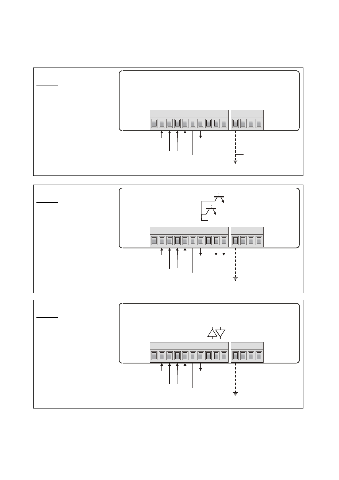
2. Terminal Assignments
8
9
G
N
D
230
VAC11
5
V
A
C0VAC
optional, see *)
n
.c.n.c.
8
9
G
N
D
230
VAC11
5
V
A
C
0VA
C
optional, see *)
8
9
G
N
D
230
VAC11
5
V
A
C0VAC
optional, siehe *)
DRxD
,A(+)
D
,
B
(
-
)
AX 345:
Basic model
1
3 4 5 6 7
10
n.c.
AX 347:
Model with two presets
and optocoupler outputs
AX 348:
Model with serial
RS232 / RS485 interface
GND217-30V DC in
1
GND217-30V DC in
Input A
Input B
AGND
GND
3 4 5 6 7
Input A
Input B
AGND
GND
+24V DC out
10
COM+
OUT 1
+24V DC out
PE
OUT 2
PE
1
3 4 5 6 7
GND217-30V DC in
Input A
Input B
AGND
GND
+24V DC out
10
Tx
GN
PE
*) The connection of PE is optional and not necessary for safety or for EMC.
However, with some applications, it can be useful to ground the common potential of all signal lines
AX34509b_e.doc / Feb-13 Page 5 / 38
Page 6

When using the earthing option, please be aware that all terminals marked GND or
AGND will be earthed.
Multiple earthing on different positions of an installation may cause problems,
especially with poor overall performance of the whole earthing and screening system!
The minus potential of analogue inputs is internally connected to the minus of the DC
supply. When you like to use current loops through several units, it is therefore
necessary to supply the units from either AC power or from several, potentialseparated DC sources.
2.1. Power supply
The unit accepts DC supply from 17 to 30 VDC with use of terminals 1 and 2. The consumption
depends on the level of the supply voltage (typical 80 mA at 30V or 130mA at 17V, plus current
taken from the aux. output).
For AC supply, terminals 0 VAC and 115 VAC or 230 VAC can be used. The total AC power is
approximately 7.5 VA.
2.2. Aux. voltage output
Terminal 7 provides an auxiliary output of 24 V DC / 100 mA max. for supply of sensors and
encoders. This is valid for AC supply and DC supply of the unit as well.
2.3. Analogue measuring inputs
There are two analogue inputs with common minus potential available (Input A and Input B).
Both refer to the AGND potential of terminal 5 which is internally connected to terminals 1, 6
and GND.
The analogue inputs can be configured for voltage input (+/- 10 V) or current input
(0 / 4 – 20 mA) by means of internal jumpers.
Ex factory, both inputs are always configured for current input.
(see section 3 for jumper settings)
AX34509b_e.doc / Feb-13 Page 6 / 38
Page 7
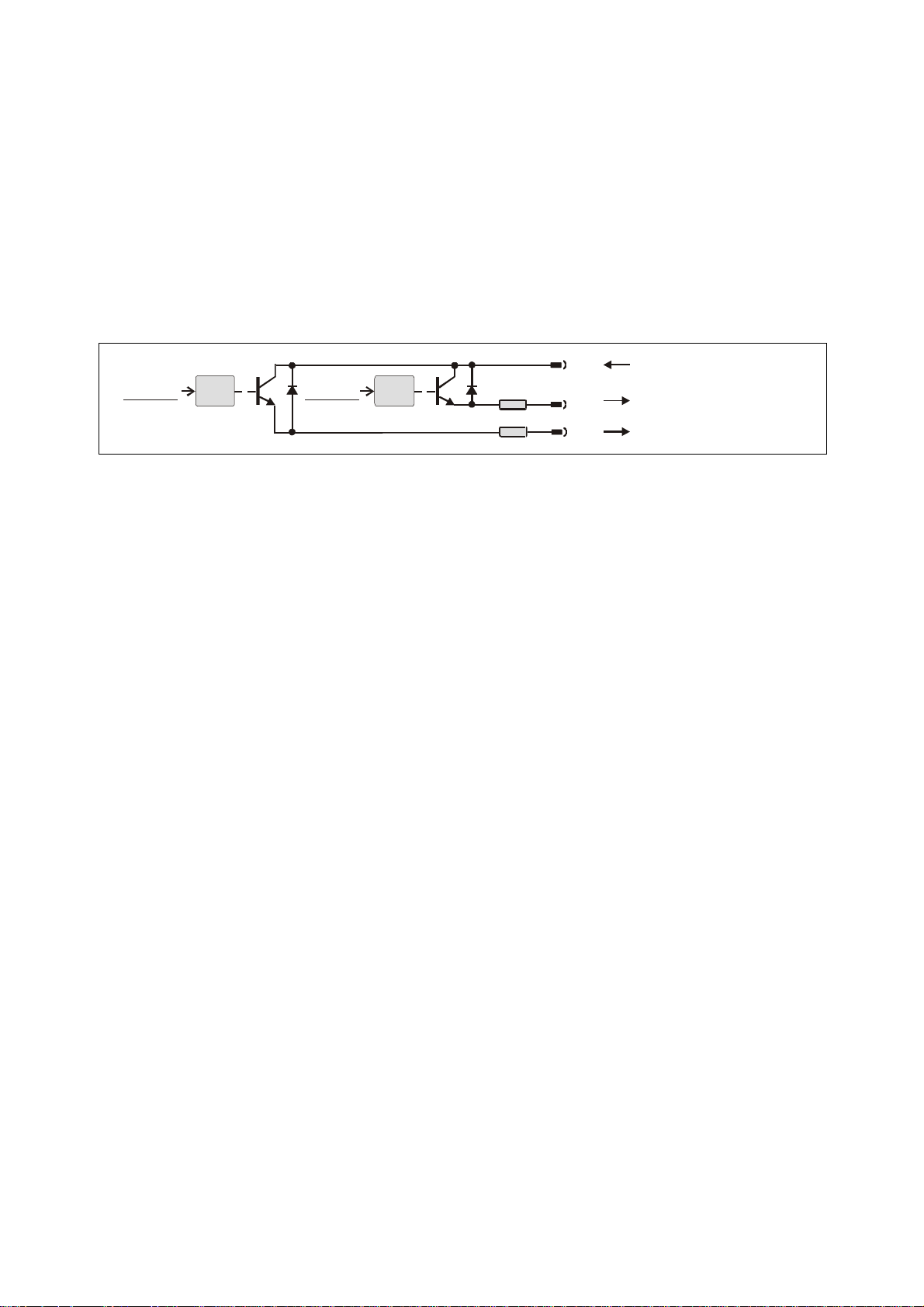
2.4. Optocoupler transistor outputs (model AX 347 only)
(8)
Com+ (5 ... 35 V)
Output 1 (max. 150 mA)
Output 2 (max. 150 mA)
The outputs provide programmable switching characteristics and are potential-free. Please
connect terminal 8 (COM+) to the positive potential of the voltage you like to switch
(range 5V....35V).
You must not exceed the maximum output current of 150mA. Where you intend to switch
inductive loads, please provide filtering of the coil by means of external diodes.
Preset2 Preset1
Opto Opto
33 R
33 R
(9)
(10)
AX34509b_e.doc / Feb-13 Page 7 / 38
Page 8
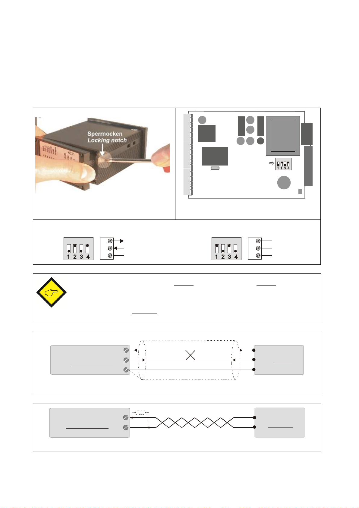
2.5. Serial RS232 / RS485 interface (AX 348 only)
ON DIP
DIL-Switch
8
910RxD
TxD
GND
8
910A (+)
B (-)
235
RxD
RxD
TxD
TxD
GND
Screen
PC
(Sub-D-9)
Connection of the RS232 interface
PLC
Connection of the RS485 interface
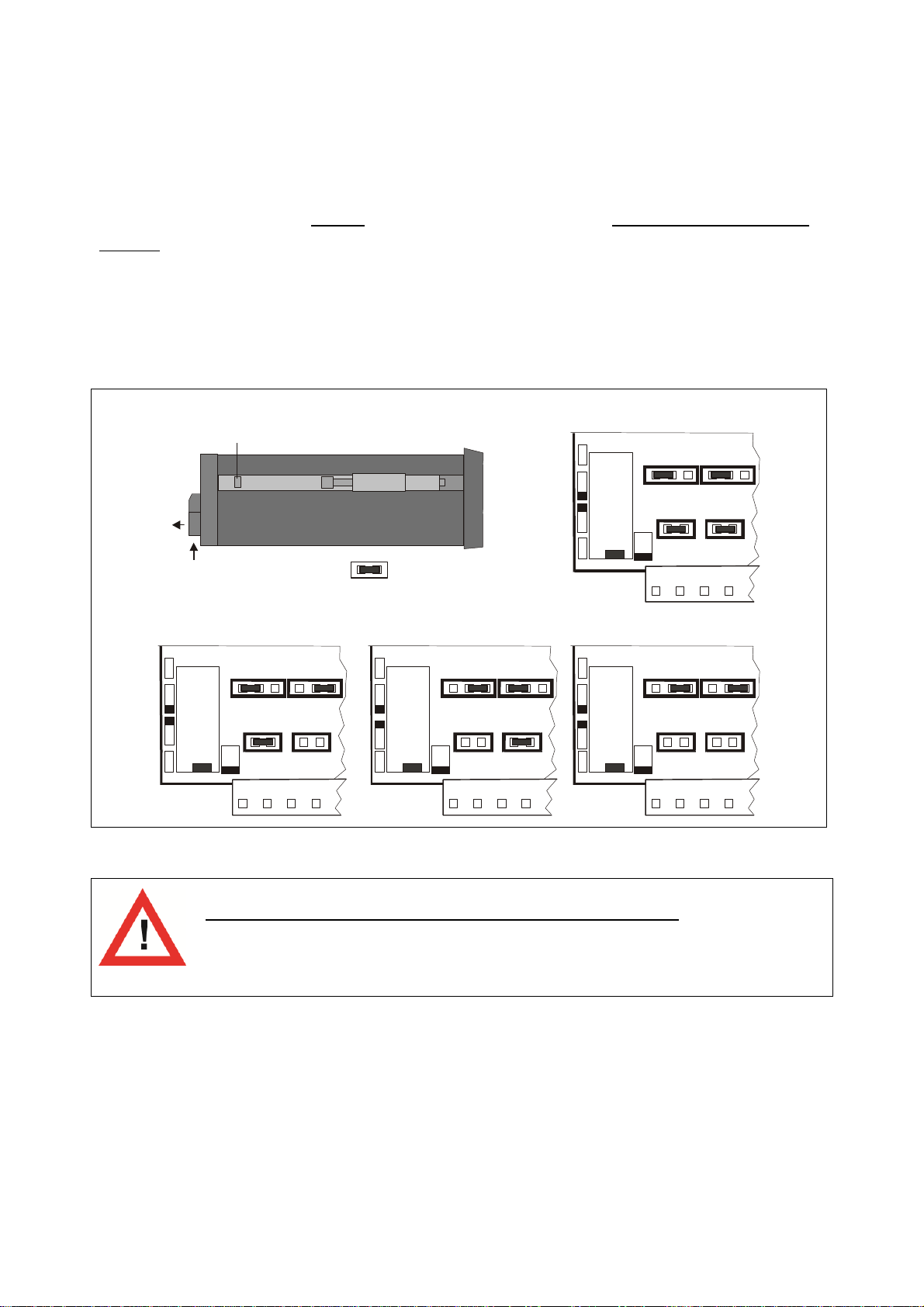
Ex factory the unit is set to RS232 communication. This setting can be changed to RS485
(2-wire) by means of an internal DIL switch. To access the DIL switch, you must remove the
screw terminal connectors and the backplane. Then pull the board to the rear to remove the
PCB from the housing.
Removal of the back plane Location of the DIL switch
ON
RS232:
ON
RS485:
Never set DIL switch positions 1 and 2 or DIL switch positions 3 and 4 to “ON”
at the same time!
After setting the switch, shift the print carefully back to the housing and avoid
damage of the front pins for connection to the front keypad plate.
9
AX 348
10
8
GND
AX 348
AX34509b_e.doc / Feb-13 Page 8 / 38
10
9
A(+)
B(-)
A(+)
B(-)
Page 9
3. Jumper settings
=jumper insered
factory preset
A=current, B =current
A = voltage, B = voltage
(mA) (V)
(mA) (V)
(mA) (V)
(mA) (V)
(mA) (V)
(mA) (V)
When your input signal is a current of 0-20 mA or 4-20 mA, there is no need to change jumper
settings and you can skip this section.
Where however you intend to use one or both inputs for voltage signals, you must change the
internal jumper settings correspondingly.
To access the jumpers, you have to disconnect the rear screw terminal strips, remove the back
plane from the unit and pull the PCB out of the housing
locking tab
screw terminal strip
A
(mA) (V)B(mA) (V)
A
(mA)B(mA)
A
A
(mA)
A = voltage, B = currentA = current, B = voltage
A
A
(mA)
B
B
(mA)
A
A
(mA)
B
B
(mA)
B
B
(mA)
AX34509b_e.doc / Feb-13 Page 9 / 38
Wrong jumper settings may cause serious damage to the unit!
After setting the jumpers, please shift the print carefully back to the housing, in order not
to damage the front pins for connection to the keypad plate.
Page 10

Current inputs are automatically scaled to an input range of 0/4 – 20 mA.
Voltage inputs use the standard range of +/- 10V.
You are free to measure voltages up to 120 volts DC by use of a remote resistance in series to
the input line (please observe applicable safety standards!). You can calculate the value from
the formula
R = resistance value
Rx [ k ] = 3 x Vx [ V ] - 30
V = input voltage
Example: Desired input = 100 volts:
R = [ 3 x 100 ] – 30 (k) = 270 k
With regard to the scaling procedure described later, the new maximum input with resistance
will work like a 10 volts signal with no resistance
AX34509b_e.doc / Feb-13 Page 10 / 38
Page 11
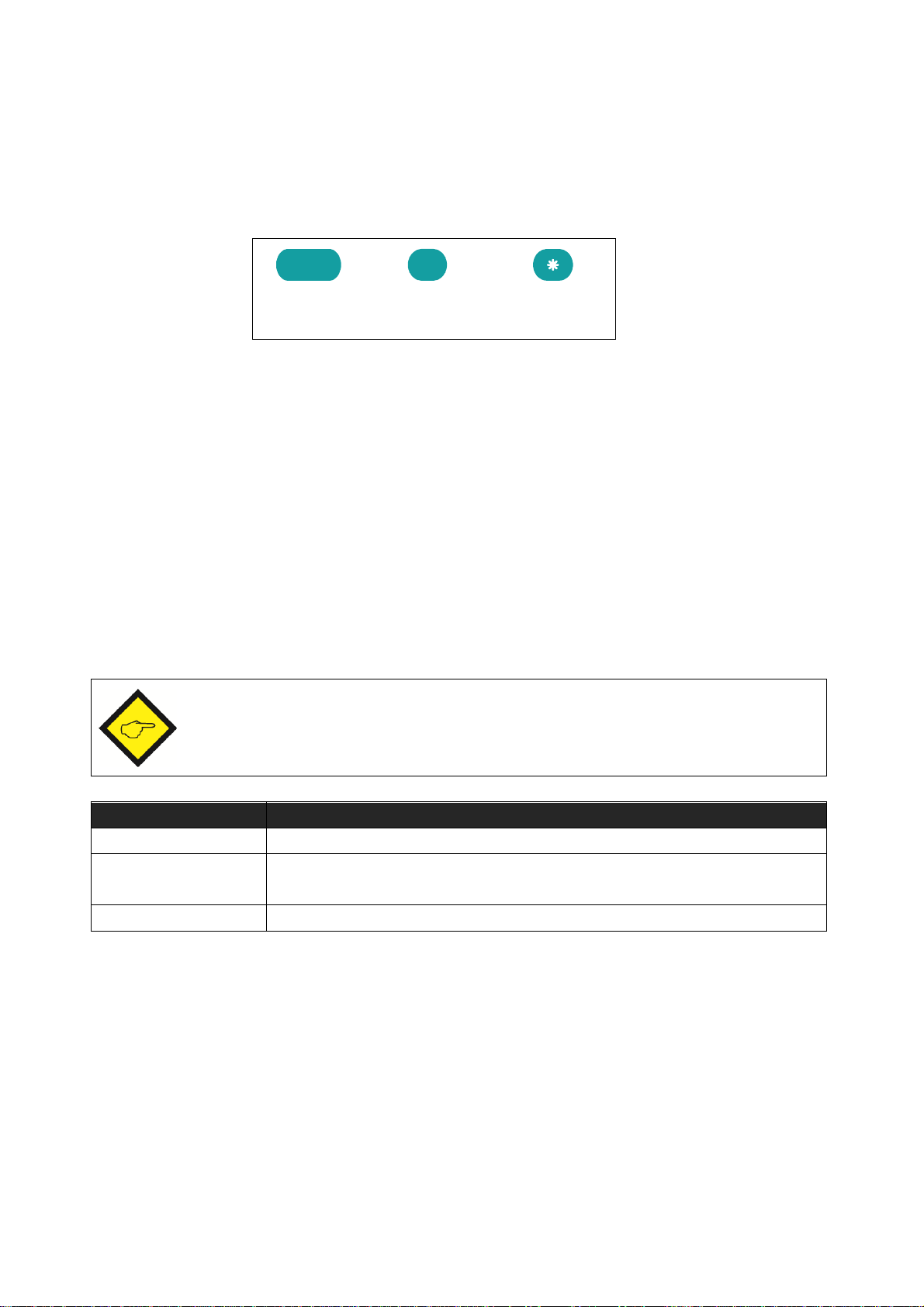
4. How to Operate the Keys
ENTER
SET
Cmd
Change over to
Key operation
Basic setup
Keep ENTER and SET down simultaneously for 3 seconds
Operational
Keep ENTER down for 3 seconds.
Teach operation
Keep SET down for 3 seconds
The unit uses 3 front keys for all setup operations. Subsequently, the key functions will be
named as shown in the table below.
(Command)
The functions of the keys are depending on the actual operating state of the unit.
The following three operating states apply:
Normal display state
Setup state
a.) Basic setup
b.) Operational parameter setup
Teach operation
4.1. Normal display state
You can change over to the other states while the unit is in the normal display state only.
parameter setup
The Cmd key is only used for execution of the Tare function, the Reset function and for
Teaching the interpolation points for linearization (see section 8).
AX34509b_e.doc / Feb-13 Page 11 / 38
Page 12

4.2. Parameter settings
4.2.1. How to select a parameter The ENTER key will scroll through the menu. The SET key allows to select the corresponding
item and to change the setting or the numeric value. After this, the selection can be stored by
ENTER again, which automatically changes over to the next menu item.
4.2.2. How to change parameter settings With numerical entries, at first the lowest digit will blink. When keeping the SET key down, the
highlighted digit will scroll in a continuous loop from 0 … 9 … 0 … 9. When you release the
SET key, the actual digit will remain and the next digit will be highlighted (blink).
This procedure allows setting all digits to the desired values. After the most significant digit
has been set, the low order digit will blink again and you can do corrections if necessary.
With signed parameters, the high order digit will only scroll between the values “0” (positive)
and “-“ (negative)
4.2.3. How to store settings To store the actual setting, press the ENTER key, which will also automatically scroll forward
the menu.
The unit changes from programming mode to normal operation when you keep down the ENTER
key again for at least 3 seconds.
4.2.4. Time-out function The “time-out” function will automatically conclude every menu level, when for a break period
of 10 seconds no key has been touched. In this case, any entry which has not been confirmed
by ENTER yet would remain unconsidered.
AX34509b_e.doc / Feb-13 Page 12 / 38
Page 13

4.3. Teach operation
Key
Function
Cmd will store the display value to the register and will change over to the
The Time-out function will be switched off during all Teach operations
ENTER will conclude or abort any Teach operation in progress
SET function is fully similar to normal set-up operation
next interpolation point.
For details of the Teach procedure see section 8.3.
4.4. Set all parameters to “Default“
At any time you can return all settings to the factory default values.
The factory default settings are shown in the parameter listings in section 6.
When you decide to set all parameters to „default“, please be aware that all
previous settings will be lost and you will need to do the whole set-up
procedure once more
To execute the „Default“ setting function:
Power the unit down.
Press the ENTER key.
Power the unit up again while the ENTER key is kept down
4.5. Code Locking of the Keypad
When the code locking of the keypad has been switched on, any key access first results in
display of
To access the menu you must press the key sequence
within 10 seconds, otherwise the unit will automatically return to the normal display mode.
AX34509b_e.doc / Feb-13 Page 13 / 38
Page 14

5. The Parameter Menu
Basic Parameters
"UPdAt”
"UPdAt”
"UPdAt”
„LinEAr"
„LinEAr"
„LinEAr"
"Crnd"
"Crnd"
"Crnd"
The menu provides one section with “basic parameters” and another section with “operational
parameters”. On the display you will only find those parameters which have been enabled by
the basic settings. E.g. when the Linearization Functions have been disabled in the basic set-up,
the associated linearization parameters will also not appear in the parameter menu.
All parameters, as good as possible, are designated by text fragments. Even though the
possibilities of forming texts are very limited with a 7-segment display, this method has proved
to be most suitable for simplification of the programming procedure.
The subsequent table is to show the general structure of the whole menu only.
Detailed descriptions of all parameters will follow in section 6.
Menu overview:
AX 345 AX 347 AX 348
„n)odE“ „n)odE“ „n)odE“
„briGht" „briGht" „briGht"
„CodE „ „CodE „ „CodE „
„Src 1 " "S-Unit"
„CHAr 1" "S-Forn"
„Src 2 " "S-bAUd"
„CHAr 2"
„HYSt 1"
„HYSt 2"
AX34509b_e.doc / Feb-13 Page 14 / 38
Page 15

Operational Parameters
Single Mode Dual Mode Combined Modes
"OFFS A" *)
"OFFS A" *)
OFFS b" *)
"P01_H " **)
"P01_Y " **)
---->"P16_H " **)
"P16_Y " **)
„PrES 1" (AX 347 only)
„PrES 2" (AX 347 only)
„inPutA" „inPutA" „inPutA"
„StArtA" „StArtA" „StArtA"
„End A" „End A" „End A"
„dPoi A" „dPoi A" „dPoi A"
„FiLt A" „FiLt A" „FiLt A"
„inPutb" „inPutb"
„StArtb" „StArtb"
„End b" „End b"
„dPoi b" „dPoi b"
„FiLt b" „FiLt b"
„n) FAc"
„d FAc"
„P FAc"
„dPoint"
"S-tim" (AX 348 only)
"S-mod" (AX 348 only)
"S-CodE" (AX 348 only)
AX34509b_e.doc / Feb-13 Page 15 / 38
*) appears only when the Offset function has been enabled
**) appears only when the linearization is switched on
Page 16

6. Setting of Parameters
Menu Text
Default
Mode of operation
Brightness of the display
Update time of the display
Keypad interlock code
Mode of linearization
6.1. Basic Parameters
In general, the parameters described subsequently must be set with the very first
commissioning of the unit only. For best comprehensibility, this section describes setup of all
display functions only as needed for model AX 345, and settings applicable to preselections
and switching outputs of AX 347 are described separately.
Single input operation (input A only)
Dual input operation (input A and input B separately)
Sum operation (input A + input B)
Differential operation (input A – input B)
Dividing operation (ratio A : B)
Multiplying operation (product A x B)
„100“
„ 100“ 100% of maximum brightness
„ 80“ 80% of maximum brightness
„ 60“ 60% of maximum brightness
„ 40“ 60% of maximum brightness
„ 20“ 20% of maximum brightness
Updates the display every x.xxx seconds. Setting range from
0.050 to 5.999 seconds.
Keypad enabled continuously
Keypad locked for any access
Keypad locked, except for access to preselections
Pres 1 und Pres 2
No linearization. The corresponding parameters will
not appear in the menu.
Linearization for the numeric range 0 – 99999.
Interpolation points to be set in the positive range
only (negative values will appear as a mirror).
Linearization over the full range
–99999 to +99999
„0.300“
AX34509b_e.doc / Feb-13 Page 16 / 38
Page 17

Menu Text
Default
Command key enable
The Command key is switched off and no Offset
values will appear in the menu
The Cmd key will execute the Tare/Offset function
The Cmd key will execute the Teach function
The Cmd key will execute both, the Tare and the
Teach function
6.2. Operational parameters
After the basic setup, you can access the operational parameters by pressing ENTER for at
least 3 seconds. You will only find those parameter texts that are relevant for your mode of
operation.
To exit the menu, keep again ENTER down for at least 3 seconds, or just wait for the automatic
Time-Out function.
AX34509b_e.doc / Feb-13 Page 17 / 38
Page 18

6.3. Modes of operation
Menu Text
Setting Range
De
fault
Input A range
Start value A
End value A
Decimal point for signal A
Average filter input A
Offset value for input A *)
6.3.1. Single mode (input A only)
Set the desired range for input A
Voltage +/-10V
Current 0-20 mA
Current 4-20 mA
Value which the unit will display with a
zero input signal of 0 volts or 0/4 mA
Value which the unit will display with a
full scale input of 10 volts or 20 mA
Select the desired position of the decimal point
000000 No decimal point
00000.0 one decimal position
---->
0.00000 five decimal positions
-99999 … 99999 0
-99999 … 99999 1000
00000.0
Adjustable floating average filter for smoothing
the display with unsteady input signals
No filtering
2,4,8,16
Offset value for the zero displacement of input
A signals
*) When the Tare function is switched on only
Number of floating averaging
cycles
-99999 … 99999 0
AX34509b_e.doc / Feb-13 Page 18 / 38
Page 19

6.3.2. Dual Mode (Inputs A and B separately)
A
B
Menu Te
xt
Input Range
Default
Input B range
Start value B
End value B
Decimal point for signal B
Average filter input B
Offset value for input B *)
With this mode, the SET key selects between display of channel A
and display of channel B, and the bar of the high order LED
indicates which of the two channels is actually in display.
Set the desired range for input B
Voltage +/-10V
Current 0-20 mA
Current 4-20 mA
Value which the unit will display with a
zero input signal of 0 volts or 0/4 mA
-99999 … 99999 0
-99999 … 99999 1000
Value which the unit will display with a
full scale input of 10 volts or 20 mA
Select the desired position of the decimal
point
000000 No decimal point
00000.0 one decimal position
---->
0.00000 five decimal positions
Adjustable floating average filter for
smoothing the display with unsteady input
signals
No filtering
2,4,8,16
Offset value for the zero displacement of
input A signals
*) When Tare function is switched on only
Number of floating averaging
cycles
000000
-99999 … 99999 0
AX34509b_e.doc / Feb-13 Page 19 / 38
Page 20

6.3.3. Combined Modes [A + B], [A - B], [A : B], [A x B]
The upper bar of the high order digit indicates that you display
Menu Text
Setting Range
Default
Proportional Scaling Factor
Reciprocal Factor
Additive Constant
Decimal Point
m_Fac
d_Fac
P_Fac
These modes allow displaying either the single channels A and B or the calculated result
according to the selected combination. The SET key allows scrolling between the three
displays.
A
channel A.
B
The lower bar of the high order digit indicates channel B.
When no bar is lit, the display shows the result of the calculation,
<AB>
according to the combination set.
When you use one of the combined modes, you will first have to do the same settings as with
the “Dual” mode for individual display of inputs A and B.
The combined display will then be the result calculated from both single values.
The following additional parameters provide a final scaling facility, so you can read out the
result of your combination in proper engineering units:
-10000 … 10000 1000
Multiplies the result by this setting
1 … 99999 1000
Divides the result by this setting
-99999 … 99999 0
Adds or subtracts this setting
000000
Sets the decimal point for the combined
display value
000000 No decimal point
00000.0 one decimal position
---->
0.00000 five decimal positions
Calculation Formula:
Final display value
AX34509b_e.doc / Feb-13 Page 20 / 38
value calculated from <AB>
=
x
+/-
Page 21

6.4. Additional settings for the Preselections (model AX 347 only)
Menu Text
Setting Range
Def
ault
Signal source of switching output „OUT1“
Output 1 switching characteristics
Signal sour
ce of switching output „OUT2“
6.4.1. Basic settings for the Presets: The basic setup menu provides the following additional parameters which are relevant for the
operation of the presets and outputs only:
OUT1 depends on analogue input A
OUT1 depends on analogue input B *)
OUT1 depends on the combination [A,B] of both
analogue inputs **)
Greater/Equal:
Output is statically active with display
greater or equal Preset.
Lower/Equal:
Output is statically active with display
lower or equal Preset.
Greater/Equal:
Output is dynamically active with
display greater or equal Preset.
(timed output impulse)
Lower/Equal:
Output is dynamically active with
display lower or equal Preset.
(timed output impulse)
OUT2 depends on analogue input A
OUT2 depends on analogue input B *)
OUT2 depends on the combination [A,B] of both
analogue inputs **)
*) Requires Analogue input B to be activated (i.e. operating mode setting "Dual" or "Combined")
**) Requires operating mode setting "Combined"
AX34509b_e.doc / Feb-13 Page 21 / 38
Page 22

Menu Text
Setting Range
Default
Output 2 switching characteristics
See above
Switching Hysteresis 1
Switching Hysteresis 2
Preset value
GE=Greater/Equal
Display value
See above
See above
See above
Output is statically active when the
display reaches the value of Preset 1 –
Preset 2 *)
Output is dynamically active when the
display reaches the value of Preset 1 –
Preset 2 *)
0 … 99999 0
Programmable Hysteresis for output 1
0 … 99999 0
Programmable Hysteresis for output 2
*) Serves to generate an anticipation signal at a fixed distance to the preset 1 signal.
The anticipation automatically follows the settings of preset 1.
6.4.2. Characteristics of the switching hysteresis The direction of operation of the Hysteresis setting depends on the selected switching
characteristics „GE“ or. „LE“ and is explained in the figure below:
Hysteresis
Hysteresis
LE=Lower/Equal
Where the switching outputs have been set to dynamic operation, the output impulse time
is always 500 msec. (fixed time, only factory adjustable)
AX34509b_e.doc / Feb-13 Page 22 / 38
Page 23

6.4.3. Operational settings for presets:
Menu Text
Setting Range
Default
Preselection 1
Preselection 2
Display
Meaning
Both outputs are OFF (output transistors in high impedance state)
Both outputs are ON (output
transistors in low impedance state))
Output 1 is ON
Output 2 is OFF
Output 1 is OFF
Output 2 is ON
The settings for the Preselection values appear at the beginning of the operational parameters:
-99999 … 99999 10000
-99999 … 99999 5000
6.4.4. Actual switching state of the outputs: At any time you can find out the actual switching state of the outputs. For this, just push the
ENTER key shortly during normal operation. The display will then provide one of the following
information for the next two seconds:
AX34509b_e.doc / Feb-13 Page 23 / 38
Page 24

When Preset 1 is used to monitor a minimum value with setting “LE”, and Preset 2 is used to
monitor a maximum value with setting “GE”, then output 1 will operate with an
Automatic Startup-Inhibit, i.e. it will become enabled only after the measuring value has crossed
the minimum setting the first time.
Where no startup-Inhibit is desired, please use Preset 1 for Maximum and Preset 2 for Minimum
control.
6.4.5. Response time of switching outputs The response time of the transistor outputs is fully independent of the selected update time for
the display. With operating mode "Single" the response time of the outputs is typically
53 msec (provided that average filter and linearization function are switched off)
Use of the average filter and the linearization function will extend the response time of the
outputs correspondingly. When the fastest possible response of the outputs is important, please
make sure that these two functions are switched off.
AX34509b_e.doc / Feb-13 Page 24 / 38
Page 25

6.5. Additional Parameters for the Serial Interface (model AX 348 only)
Menu
Setting Range
Defa
ult
6.5.1. Communication settings in the Basic Menu:
Unit Number
You can assign any unit number between
11 and 99. The address must however not contain a
“0“ because such numbers are reserved for collective
addressing of several units.
Serial Data Format
The first character indicates the number of data bits.
The second character specifies the Parity Bit
„Even“, "Odd“ or no Parity Bit.
The third character indicates the number of Stop Bits.
0..99 11
Baud Rate
The following Baud Rates can be set for
communication:
AX34509b_e.doc / Feb-13 Page 25 / 38
Page 26

6.5.2. Operational Parameters for configuration of the interface:
Menu
Setting Range
Default
Serial Timer:
Setting 0,000 allows manual activation of a serial data
transmission at any time. All other settings specify the cycle
time for automatic transmission, when the interface is set to
"Printer Mode"
Between two transmission cycles the unit will allow a pause
depending on the baud rate. The minimum cycle times for
timer transmissions are shown in the table.
Baud Rate Minimum Cycle Time [ms]
600 384
1200 192
2400 96
4800 48
9600 24
19200 12
38400 6
Serial Mode:
PC: Operation according to communication profile
(see 6.5.3)
Print1: Transmission of string type 1 (see 6.5.4)
Print2: Transmission of string type 2 (see 6.5.4)
0,000
0,010 sec
…
9.999 sec
0,100 sec
Serial Register-Code:
Specifies the register code of the data to be transmitted.
The most important register codes are:
Register S-Code ASCII
Actual display value 101 :1
Analogue input A *) 106 :6
Analogue input B *) 107 :7
Display channel A 113 ;3
Display channel B 114 ;4
Display channel [A,B] combined 115 ;5
*) Normalized analogue input values, scaling 0 ... 10 000 for 0% to 100% of full scale input signal
100
...
120
101
AX34509b_e.doc / Feb-13 Page 26 / 38
Page 27

6.5.3. PC-Mode
EOT
AD1
AD2
C1C2ENQ
EOT = Control Character (Hex 04)
STXC1C2
x x x x x x x
ETX
BCC
STX = Control Character (Hex 02)
Communication with PC - Mode allows free readout of all parameters and registers of the unit.
The subsequent example shows the details of communication for serial readout of the actual
display value.
The general string to initiate a request has
the following format:
AD1 = Unit Address, High Byte
AD2 = Unit Address, Low Byte
C1 = Register Code, High Byte
C2 = Register Code, Low Byte
ENQ = Control Character (Hex 05)
Example:
Request string for readout of the actual display data from a unit with serial address No. 11:
ASCII-Code: EOT 1 1 : 1 ENQ
Hexadecimal: 04 31 31 3A 31 05
Binary 0000 0100 0011 0001 0011 0001 0011 1010 0011 0001 0000 0101
With a correct request the unit will
respond with the adjoining response
string. Leading zeros will be suppressed.
BCC provides a „Block Check Character“,
formed by Exclusive-OR of all characters
from C1 through ETX.
C1 = Register Code, High Byte
C2 = Register Code, Low Byte
x x x x x = Data (display value)
ETX = Control Character (Hex 03)
BCC = Block Check Character
With inaccurate request strings the unit would only respond "STX C1 C2 EOT" or just "NAK".
Assumed that the actual display value is "-180", the response of the unit would be
ASCII STX : 1 - 1 8 0 ETX BCC
Hex 02 3A 31 2D 31 38 30 03 1C
Bin 0000
0010
0011
1010
0011
0001
0010
1101
0011
0001
0011
1000
0011
0000
0000
0011
0001
1100
Again, the block check character "BCC" is calculated from the Exclusive-OR of all characters
from C1 through ETX.
AX34509b_e.doc / Feb-13 Page 27 / 38
Page 28

6.5.4. Printer Mode
„S-mod“
Transmission String Type
+/-XXXXXXLF
CR
+/-XXXXXXCR
Cyclic (timed)
Set the Serial Timer to any value
0.010 sec.
Manual activation of
Set the Serial Timer to 0.000.
The Printer Mode allows cyclic or manual activation of transmissions of the specified register
data. The corresponding register can be specified by means of parameter „S-Code“.
Another parameter named „S-mod“ allows selection between two different string types:
„Print1“
„Print2“
Space Sign Data Line
Sign Data Carriage
The mode of activation of serial transmissions can be determined as follows:
≥
transmissions:
Select the desired string type by parameter "S-mod"
After exit from the menu the transmissions will start automatically
transmissions
Select the desired string type by parameter "S-mod"
After exit from the menu a transmission can be activated at any time
by shortly pressing the ENTER key
feed
return
Carriage
return
AX34509b_e.doc / Feb-13 Page 28 / 38
Page 29

7. Commissioning
Step
Action
See section
1
Analogue i
nputs
32Basic settings
6.1
6.13Parameter settings
6.3.1 and 6.3.2
6.4
6.54Supplementary
8
Commissioning of this unit is easy and uncomplicated when following the subsequent steps:
Set jumpers
Select Operation mode
Keep linearization and Tare function off firstly
Configuration of the analogue inputs, scaling
of the display
6.3.3
functions
Select combination and final scaling
(if applicable)
Configuration of switching outputs (AX 347)
(if applicable)
Configuration of the serial interface
Set Tare function and Linearization
(if applicable)
A Set-Up Form is available in the appendix of this manual, which may be used for a most
convenient and clearly arranged setup procedure.
It is advisable to do settings for Tare and linearization functions quite at the end, after all other
functions have already proved to work fine.
AX34509b_e.doc / Feb-13 Page 29 / 38
Page 30

8. Special Functions
8.1. Tare / Offset function
This function will become active after the “Cmd” parameter has been set to “oFFSEt” or to
“both”(see 6.1). As a result, every touch of the “Cmd” key will store the actual display value to
the Offset register, resulting in a Zero display with the actual input signal.
8.2. Linearization
This function allows converting non-linear input signals into a linear presentation or vice-versa.
There are 16 interpolation points available, which can be freely arranged over the whole
measuring range in any distance. Between two points the unit automatically will interpolate
straight lines.
For this reason it is advisable to set many points into areas with strong bending, and to use
only a few points in areas with little bending. „Linearization Mode“ has to be set to either „1quA“ or „4-quA“ to enable the linearization function (see subsequent drawing). This will change
the linear measuring results into a non-linear display.
Parameters P01_x to P16_x select 16 x- coordinates, representing the display values which the
unit would normally show in the display. With parameters P01_y to P16_y you can specify now,
which values you would like to display instead of the corresponding _x values.
This means e.g. that the unit will replace the previous P02_x value by the new P02_y value.
With respect to the consistency of the linearization, the x- registers have to use continuously
increasing values, e.g. the x- registers must conform to the constraint
P01_X < P02_X < … < P15_X < P16_X.
Independent of the selected linearization mode, the possible setting range of all registers
P01_x, P01_y,…, P16_x, P16_y is always -99999 … 99999.
For measuring values lower than P01_x, the linearization result will always be P01_y.
For measuring values higher than P16_x, the linearization result will always be P16_y.
With operation modes “Single” and Dual”, all linearization refers to input channel A only.
With all combined operation modes, linearization refers to the calculated final result of the
selected combination.
AX34509b_e.doc / Feb-13 Page 30 / 38
Page 31
y
xyLinearisation Mode = 4_quA
P1(x)= -1000
P1(y)= 900
P
0
1
_
xP1
0
_
x
P
1
6
_
x
P01_y
P07_y
P15_y
P16_y
Pressure
Volume
P
1
5
_
x
P10_y
P16(x)= 1000
P16(y)= 800
P8(x)= 0
P8(y)= 750
x
P16(x)= +1000
P16(y)= - 600
*)
P1(x)= 0
P1(y)= 0
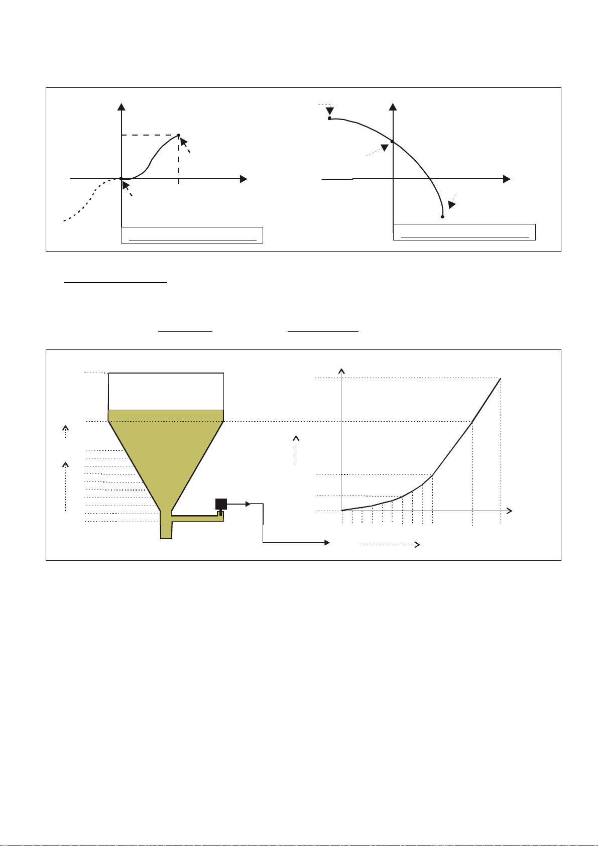
Linearisation Mode = 1_quA
Application Example:
We like to display the filling quantity (volume) of a tank as shown below, with use of a pressure
sensor mounted to the bottom of the tank. With this application the analogue pressure signal is
proportional to the filling level, but not to the filling quantity.
P16_x
P15_x
P10_x
Pressure
Sensor
P01_x
0-20 mA
To solve the problem, we divide the non-linear part of the tank into 14 parts. We enter the
expected display values of the pressure sensor to registers P01_x to P15 _x.
For the linear part of the tank it is sufficient to store the final pressure value to register P16_x.
Now we can easily calculate the appropriate filling quantities and enter these values to the
registers P01_y to P16_y.
AX34509b_e.doc / Feb-13 Page 31 / 38
Page 32

8.3. Manual input or „Teaching“ of the interpolation points
Interpolation points to form the linearization curve can be entered one after another, using the
same procedure as for all other numeric parameters. This means you will enter all parameters
P01_x to P16_x and P01_y to P16_y manually by keypad.
During manual input of interpolation points the unit will not examine the settings
P01_x to P16_x. Therefore the operator is responsible to observe the constraint
P01_X < P02_X < … < P15_X < P16_X.
In many cases it should however be more convenient to use the Teach function. Here you have
to sequentially apply all the x-values to the analogue input, and just add the corresponding
y-values by keypad.
Preparation for teaching:
Please select the desired range of linearization (see section 6.1).
Please set the basic parameter “Cmd” to “tEACH” or “both” (see section 6.1).
After this, the teach function is ready to start.
How to use the Teach Function:
Hold down the “Cmd” key for 3 seconds, until the display shows “tEACh”. Now you are
in the Teach mode.
To exit the teach mode again, you have the following two possibilities:
1. Press the enter key for 2 seconds. On the display you will read “StOP” for a short time, and
then the unit will switch back to the normal mode.
2. Just do nothing. After 10 seconds the unit will switch back to the normal mode automatically.
In both cases the parameters of linearization P01_X to P16_Y will not change.
To start the teach procedure please press “Cmd” again within the next 10 seconds. The
display will show “P01_X”.
With respect to the consistency of the linearization, all parameters from
P01_X to P16_Y will be overwritten by suitable initial values.
Initial values for „P01_X“ and „P01_Y“ are -99999, all other values will start with 99999
Press once more “Cmd” to display the actual analogue input signal. Now arrange for the
desired analogue input signal of the first interpolation point (with combined modes
please arrange for both analogue signals)
AX34509b_e.doc / Feb-13 Page 32 / 38
Page 33

When you read the x-value of your first interpolation point in the display, press “Cmd”
again. This will automatically store the actual display value to the P01_x register, and
for about 1 second you will read “P01_y “ on the display, followed again by the same
reading stored previously.
This display value now can be edited to the desired P01_y value, like a regular
parameter
When you read the desired P01_y value in your display, store it by pressing “Cmd”
again. This will automatically cycle the display to the next interpolation point P02_x.
The unit will examine the constraint valid for the x-values of interpolation points.
Every interpolation point must be higher than its preceding point.
Where this constraint is breached, all 6 decimal points will blink automatically as a
warning. Pressing the CMD key will not store the illegal value, but result in an error text
"E.r.r.-.L.O." as a warning.
Once you have reached and stored the last interpolation points P16_x/y, the routine will
restart with P01_x again, and you are free to double-check your settings once more.
To conclude the Teach procedure, press the ENTER key. As a result you will read “StOP”
for about 2 seconds, before the unit returns to the normal operation. All linearization
points will at the same time be finally stored.
AX34509b_e.doc / Feb-13 Page 33 / 38
Page 34

8.4. Overflow and Underflow Control
Display
Input A
Input B
Underflow
o.kOverflow
o.k
o.k
Underflow
o.k
Overflow
Underflow
Underflow
Overflow
Underflow
Underflow
Overflow
Overflow
Overflow
The unit continuously monitors both input channels for possible overflow or underflow
situations (input signal out of specified range)
Overflow: the analogue input signal is greater than +10,2 V or +20,4 mA
Underflow: the analogue input signal is lower than -10,2 V or -0,4 mA
Any out-of-range situation will cause a message according the table below:
AX34509b_e.doc / Feb-13 Page 34 / 38
Page 35

9. Technical Specifications
110,0 (4.331’’)
44,0(1.732)
4
8,0(1.890
)
9.1. Dimensions
96,0 (3.780’’)
9,0 (.345)
8,0
(.315)
10,0
(.394)
129,0 (5.079)
140,5 (5.531)
91,0 (3.583)
Panel cut out: 91 x 44 mm (3.583 x 1.732’’)
AX34509b_e.doc / Feb-13 Page 35 / 38
Page 36

9.2. Technical data
Power supply AC
:
115/230 V (+/
-
12,5 %), 7,5 VA
Power supply DC
:
24 V (17
–
30 V), approx. 100 mA (without aux. sensor supply)
Ripple
:≤10% @ 24VDC
Total AC power
:
DC current consumption
:
18 V : 110 mA, 24 V : 90 mA, 30 V : 80 mA
Aux. output for sensors
:
24 V DC, +/
-
15%, 100 mA (with AC and DC power input)
Inputs
:
2 analogue inputs (+/
-
10 V, 0 ..
. +20 mA, 4 ... +20 mA)
Input impedance
:
Current: Ri = 100 Ohms, Voltage: Ri = 30 kOhms
Resolution
:
Accuracy
:+/-
0.1%, +/
-
1 digit
Switching outputs
:
2 x PNP, max. 35 V, max. 150 mA
Serial interface
:
RS 232 / RS 485, 600
-
38 400 bauds
Ambient temperature
:
Operation: 0°
-
45° ( 32
–
113°F)
Housing
:
Norly UL94
–V-0Display
:
6 decades LED, high
-
efficiency ora
nge, 15 mm (0.590’’)
Ambient temperature
:
Operation: 0°
-
45° ( 32
–
113°F)
Protection class
:
IP65 (front), IP20 (rear)
Screw terminals
:
Signal lines max. 1.5 mm² (.0023 sq.in.)
Minimum update time
:
50 msec (display)
:
53 msec (switching outputs)
Conformity and standards
:
EMC 2004/108/EC:
EN 61000
-6-
2
(without sensors)
7,5 VA
14 bits (13 bits + sign)
(AX 347 only)
(AX 348 only)
minimum response time 53 msec.
Storage: -25° - +70° (-13 – 158°F)
Storage: -25° - +70° (-13 – 158°F)
AC lines max. 2.5 mm² (.0039 sq.in.)
LV 2006/95/EC: EN 61010-1
AX34509b_e.doc / Feb-13 Page 36 / 38
EN 61000-6-3
Page 37

9.3. Commissioning Form
Date:
Software:
Operator:
Serial No.:
Basic Settings: Operating mode: Code:
Brightness: Linearization:
Display Update [sec]: Cmd key command:
Model AX347 Source 1: Source 2:
Switch characteristics 1: Switch characteristics 2:
Hysteresis 1: Hysteresis 2:
Model AX348 Serial unit No.: Serial format:
Serial Baud Rate:
Analogue Inputs: Input A Input B
Input range:
Start value:
End value:
Decimal point:
Filter:
Offset :
Combined modes:
(A+B, A-B, A:B, AxB) Proportional factor:
Reciprocal factor:
Additive constant:
Decimal point:
Additional parameters:
Model AX347 Preselection 1: Preselection 2:
Model AX348 Serial Timer [s]: Serial Mode:
Serial Code:
AX34509b_e.doc / Feb-13 Page 37 / 38
Page 38

Linearization:
P01_X:
P01_Y:
P09_X:
P09_Y:
P02_X:
P02_Y:
P10_X:
P10_Y:
P03_X:
P03_Y:
P11_X:
P11_Y:
P04_X:
P04_Y:
P12_X:
P12_Y:
P05_X:
P05_Y:
P13_X:
P13_Y:
P06_X:
P06_Y:
P14_X:
P14_Y:
P07_X:
P07_Y:
P15_X:
P15_Y:
P08_X:
P08_Y:
P16_X:
P16_Y:
AX34509b_e.doc / Feb-13 Page 38 / 38
 Loading...