

Operating Manual
motrona GmbH, Zeppelinstraße 16, DE - 78244 Gottmadingen, Tel. +49 (0) 7731 9332-0, Fax +49 (0) 7731 9332-30, info@motrona.com, www.motrona.com
touchMATRIX® Indicator 7788.5150 / 7788.5155
Frequency counter, tachometer and speed indicator with touchscreen and graphic display
Product features:
• Multifunction unit with operating modes for incremental encoders (tachometer, pulse counter, position
indicator)
- Operating modes as frequency display and / or position display (pulse counter)
- Universal incremental inputs (HTL / TTL / RS422) for NPN / PNP / NAMUR encoders and sensors
- Functions such as links (eg A+B, A-B, ...), scaling, filters, start-up delay, ...
• Bright and high-contrast display with event controlled color variations
• Emulation of a 7-segment display inclusively icons and units
• Intuitive and easy parameterization by plain text and touchscreen
• 5 / 24 V auxiliary output for encoder supply
• Input frequencies up to 1 MHz
• Linearization with 24 interpolation points
• 96 x 48 mm (3.78 x 1.89 inch) norm panel housing and IP65 protection
Available options:
7788.5150: Basic unit with HTL inputs (A, B), 3 control inputs
7788.5155: Basic unit with HTL/RS422 inputs (A, /A, B, /B), 3 control inputs
• Option AC: Power supply 115 … 230 VAC
• Option AO: 16 bit analog output, 4 control outputs, serial RS232 interface
• Option AR: 16 bit analog output, 4 control outputs, serial RS485 interface
• Option CO: 4 control outputs, serial RS232 interface
• Option CR: 4 control outputs, serial RS485 interface
• Option RL: 2 relay outputs
Options can be combined

7788_5150_01a_oi_e.docx / Jan-21 page 2 / 72
Version:
Description
7788.5150_01a_oi/mbo/Jan-21
First Version
Legal notices:
All contents included in this manual are protected by the terms of use and copyrights of motrona
GmbH. Any reproduction, modification, usage or publication in other electronic and printed media as
well as in the internet requires prior written authorization by motrona GmbH.
7788_5150_01a_oi_e.docx / Jan-21 page 3 / 72
Table of Contents
Safety Instructions and Responsibility .......................................................................... 5
General Safety Instructions ............................................................................................................. 5
Use according to the intended purpose .......................................................................................... 5
Installation ....................................................................................................................................... 6
Cleaning, Maintenance and Service Notes..................................................................................... 6
Introduction .................................................................................................................. 7
Operation mode ............................................................................................................................... 7
Function diagram ............................................................................................................................. 8
Electrical Connections .................................................................................................. 9
DC Power Supply ............................................................................................................................. 9
Auxiliary Voltage Output.................................................................................................................. 9
7788.5150: Incremental Input A, B ................................................................................................ 10
7788.5155: Incremental Input A, /A, B, /B .................................................................................... 11
Control Inputs ................................................................................................................................. 12
Analog Output (Option AO/AR) ...................................................................................................... 12
Serial interface (Option AO/AR/CO/CR) ........................................................................................ 13
Control-Output (AO/AR/CO/CR) ..................................................................................................... 13
AC Power supply (Option AC) ........................................................................................................ 14
Relay-Output (Option RL) ............................................................................................................... 14
Display and touch screen ........................................................................................... 15
Screen structure for parametrization ............................................................................................ 15
Screen structure in operation ........................................................................................................ 16
Error messages .............................................................................................................................. 18
Parameter / Overview-Menu Structure ....................................................................... 19
General Menu ................................................................................................................................ 21
Speed A Settings ........................................................................................................................... 23
Speed B Settings ........................................................................................................................... 26
Counter A Settings ......................................................................................................................... 29
Counter B Settings ......................................................................................................................... 33
Collection Settings ......................................................................................................................... 36
Scaling Settings ............................................................................................................................. 37
Preselection Values ....................................................................................................................... 38
Preselection 1 Menu ...................................................................................................................... 39
Preselection 2 Menu ...................................................................................................................... 43
Preselection 3 Menu ...................................................................................................................... 44
Preselection 4 Menu ...................................................................................................................... 45
Serial Menu ................................................................................................................................... 46
Analog Menu ................................................................................................................................. 48
Command Menu ............................................................................................................................. 50
Display Menu ................................................................................................................................. 53
Linearization Menu ........................................................................................................................ 57
Appendix .................................................................................................................... 58
Data readout via serial interface ................................................................................................... 58
Modbus RTU Interface ................................................................................................................... 59
Parameter setting ....................................................................................................................................... 59
Modbus Communication ............................................................................................................................. 60

7788_5150_01a_oi_e.docx / Jan-21 page 4 / 72
Diagnostics ................................................................................................................................................. 62
Parameter / serial codes................................................................................................................ 62
Linearization ................................................................................................................................... 68
Dimensions .................................................................................................................................... 70
Technical specifications ................................................................................................................ 71

7788_5150_01a_oi_e.docx / Jan-21 page 5 / 72
Safety Instructions and Responsibility
General Safety Instructions
This operation manual is a significant component of the unit and includes important rules and hints about
the installation, function and usage. Non-observance can result in damage and/or impairment of the
functions to the unit or the machine or even in injury to persons using the equipment!
Please read the following instructions carefully before operating the device and observe all safety and
warning instructions! Keep the manual for later use.
A pertinent qualification of the respective staff is a fundamental requirement in order to use these
manual. The unit must be installed, connected and put into operation by a qualified electrician.
Liability exclusion: The manufacturer is not liable for personal injury and/or damage to property and for
consequential damage, due to incorrect handling, installation and operation. Further claims, due to errors
in the operation manual as well as misinterpretations are excluded from liability.
In addition the manufacturer reserves the right to modify the hardware, software or operation manual at
any time and without prior notice. Therefore, there might be minor differences between the unit and the
descriptions in operation manual.
The raiser respectively positioner is exclusively responsible for the safety of the system and equipment
where the unit will be integrated.
During installation or maintenance all general and also all country- and application-specific safety rules
and standards must be observed.
If the device is used in processes, where a failure or faulty operation could damage the system or injure
persons, appropriate precautions to avoid such consequences must be taken.
Use according to the intended purpose
The unit is intended exclusively for use in industrial machines, constructions and systems. Nonconforming usage does not correspond to the provisions and lies within the sole responsibility of the
user. The manufacturer is not liable for damages which have arisen through unsuitable and improper use.
Please note that device may only be installed in proper form and used in a technically perfect condition
(in accordance to the Technical Specifications). The device is not suitable for operation in explosion-proof
areas or areas which are excluded by the EN 61010-1 standard.

7788_5150_01a_oi_e.docx / Jan-21 page 6 / 72
Installation
The device is only allowed to be installed and operated within the permissible temperature range. Please
ensure an adequate ventilation and avoid all direct contact between the device and hot or aggressive
gases and liquids.
Before installation or maintenance, the unit must be disconnected from all voltage-sources. Further it
must be ensured that no danger can arise by touching the disconnected voltage-sources.
Devices which are supplied by AC-voltages must be connected exclusively by switches, respectively
circuit-breakers with the low voltage network. The switch or circuit-breaker must be placed as near as
possible to the device and further indicated as separator.
Incoming as well as outgoing wires and wires for extra low voltages (ELV) must be separated from
dangerous electrical cables (SELV circuits) by using a double resp. increased isolation.
All selected wires and isolations must be conform to the provided voltage- and temperature-ranges.
Further all country- and application-specific standards, which are relevant for structure, form and quality
of the wires, must be ensured. Indications about the permissible wire cross-sections for wiring are
described in the Technical Specifications.
Before first start-up it must be ensured that all connections and wires are firmly seated and secured in
the screw terminals. All (inclusively unused) terminals must be fastened by turning the relevant screws
clockwise up to the stop.
Overvoltages at the connections must be limited to values in accordance to the overvoltage category II.
For placement, wiring, environmental conditions as well as shielding and earthing/grounding of the supply
lines the general standards of industrial automation industry and the specific shielding instructions of the
manufacturer are valid. Please find all respective hints and rules on
https://www.motrona.com/en/support --> “[General EMC Rules for Wiring, Screening and Earthing]”.
Cleaning, Maintenance and Service Notes
To clean the front of the unit please use only a slightly damp (not wet!), soft cloth. For the rear no
cleaning is necessary. For an unscheduled, individual cleaning of the rear the maintenance staff or
assembler is self-responsible.
During normal operation no maintenance is necessary. In case of unexpected problems, failures or
malfunctions the device must be shipped for back to the manufacturer for checking, adjustment and
reparation (if necessary). Unauthorized opening and repairing can have negative effects or failures to the
protection-measures of the unit.

7788_5150_01a_oi_e.docx / Jan-21 page 7 / 72
Introduction
This series of display unit is suitable for HTL impulse signals and panel mounting. It is very versatile in
use, due to the intuitive handling and the extensive range of functions and options.
Operation mode
All functions are can be configured in the parameter menu.
The device can be set to one of the following operation modes:
• Operation as frequency display for incremental input signals
- Measurement of frequency / RMP indicator
- Tachometers / speed indicator
- Monitoring functions for speed and standstill
- Possibility of linking (A+B, B/A, ...) of both channels
(e.g., ratio or percentage deviation)
• Operation as position indicator / counter for incremental input signals
- Pulse counter
- Up- or down counter
- Position indicator
- Protractor
- Quadrature counter
- Batch counter / total counter
- Possibility of linking (A+B, B/A, ...) of both channels
(e.g., ratio or percentage deviation)
• Operation as speed- and position indicator for incremental input signals
7788_5150_01a_oi_e.docx / Jan-21 page 8 / 72
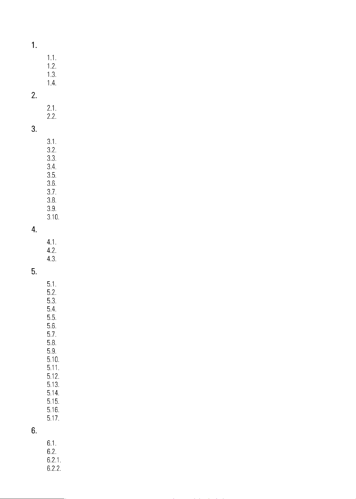
Function diagram
7788_5150_01a_oi_e.docx / Jan-21 page 9 / 72
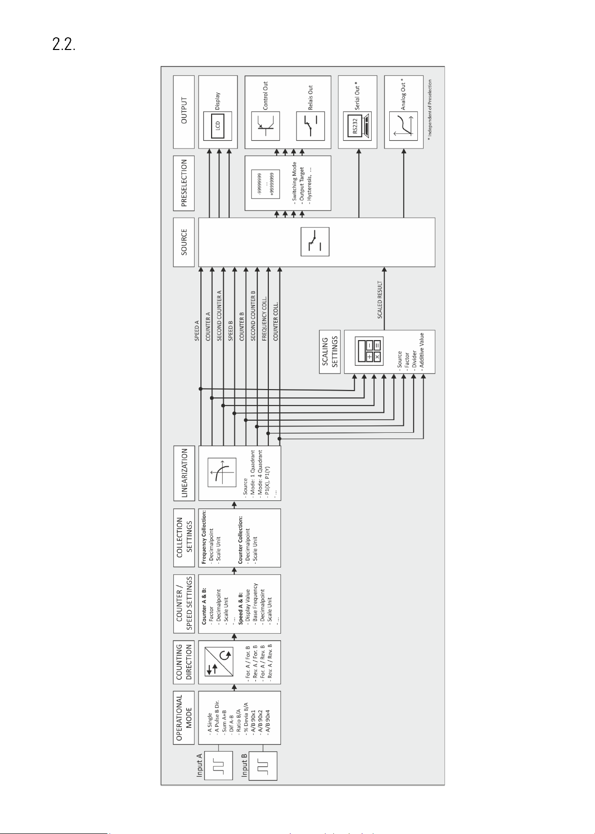
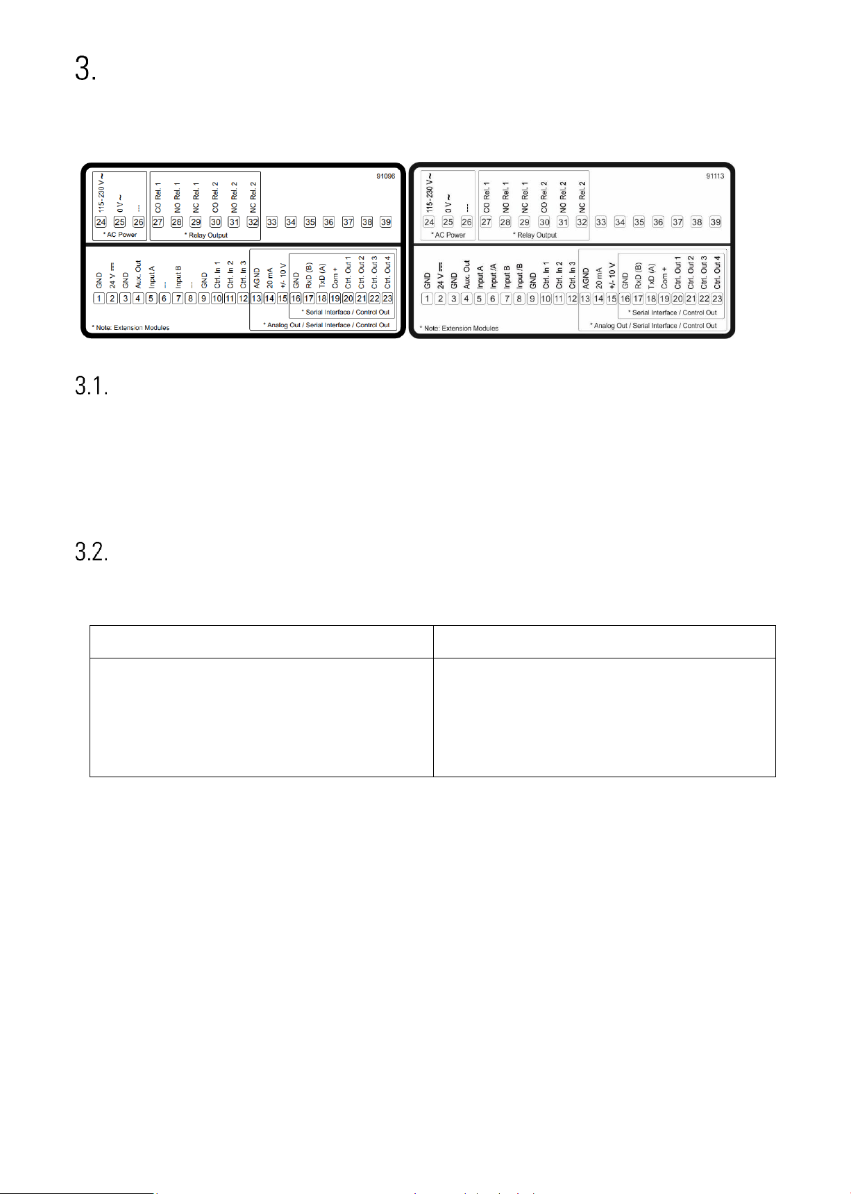
Electrical Connections
The terminal screws should be tightened with a slotted screwdriver (blade width 2mm).
7788.5150 7788.5155
DC Power Supply
The unit accepts DC supply from 18 to 30 V at the terminals 1 and 2. The power consumption depends on
the level of the supply voltage with aprox. 100 mA and the additional current required at the Auxiliary
Voltage Output.
All GND terminals are internally interconnected.
Auxiliary Voltage Output
Terminal 3 and 4 provide an auxiliary output for supply of sensors and encoders.
The output voltage depends on the power supply.
DC version
AC version
The encoder voltage is approx. 1 V lower than
the power supply voltage at terminal 1 and 2
and should be loaded with max. 250 mA.
The encoder voltage is 24 VDC (± 15%) and
should be loaded with max. 150 mA up to 45
degrees Celsius. At higher temperature the
maximum output current is reduced to 80 mA.
At 7788.5155 devices, the auxiliary voltages output is switchable from 24 VDC to 5 VDC.
7788_5150_01a_oi_e.docx / Jan-21 page 10 / 72
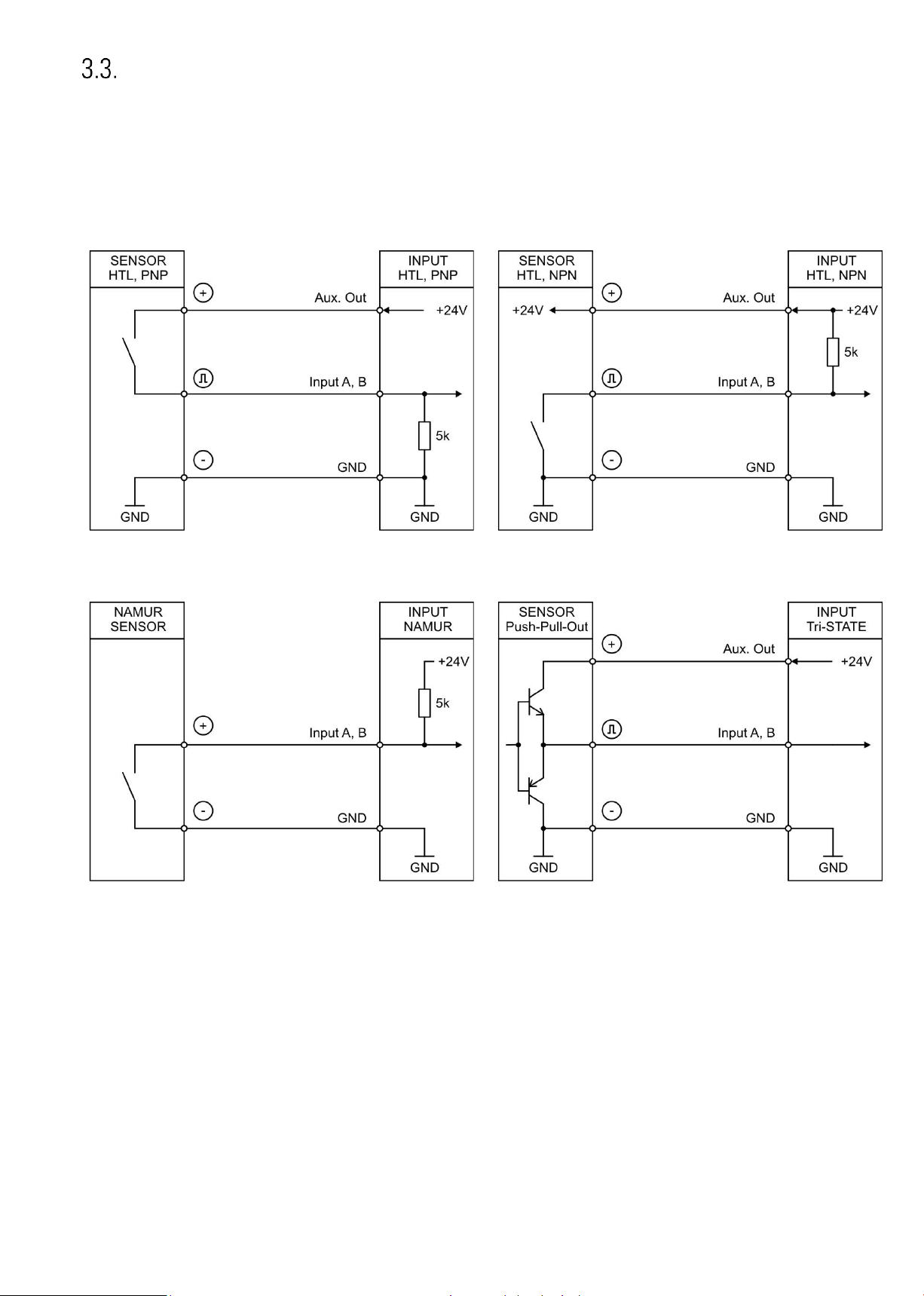
7788.5150: Incremental Input A, B
The unit provides two inputs at terminal 5 and 7 for HTL signals.
The characteristics of the incremental input (PNP, NPN, Namur or Tri-State) can be set in the GENERAL
MENU.
Wiring of the incremental inputs:
PNP
NPN
Namur
Tri-State
Unconnected PNP inputs are always “LOW” and unconnected NPN inputs are always “HIGH”.
All inputs are designed to receive impulses from electrical impulse sources.
Notice for mechanical switching contacts:
When exceptionally mechanical contacts are used, please connect an external capacitor between GND (-)
and the corresponding input (+). A capacity of 10 µF will reduce the input frequency to
20 Hz and miscounting due to contact bouncing will be eliminated.
7788_5150_01a_oi_e.docx / Jan-21 page 11 / 72
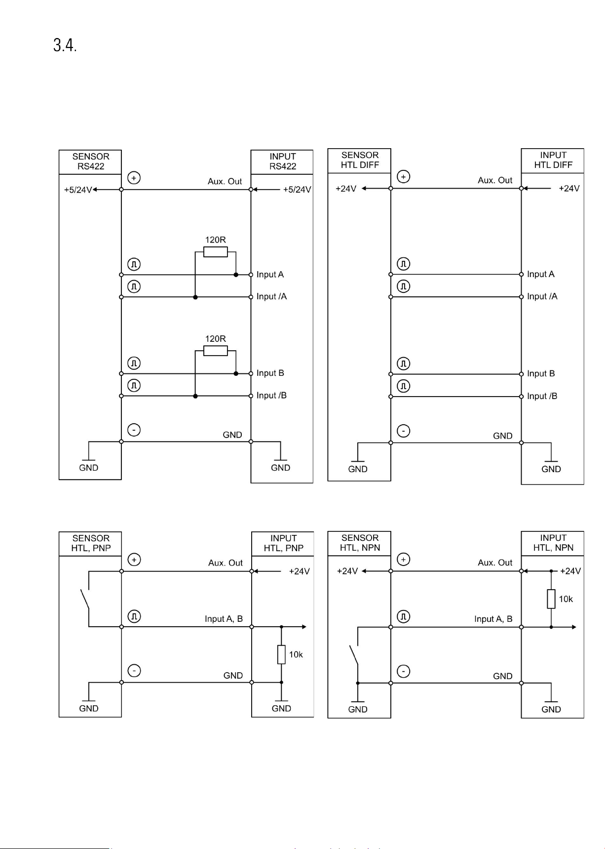
7788.5155: Incremental Input A, /A, B, /B
The unit provides two pulse inputs at terminal 5, 6, 7 and 8 for HTL/RS422 signals.
The characteristics of the incremental input can be set in the GENERAL MENU.
Wiring of the incremental inputs:
RS422
HTL DIFFERENTIAL
HTL PNP, single ended
HTL NPN, single ended
Unconnected PNP inputs are always “LOW” and unconnected NPN inputs are always “HIGH”.
All inputs are designed to receive impulses from electrical impulse sources.
7788_5150_01a_oi_e.docx / Jan-21 page 12 / 72
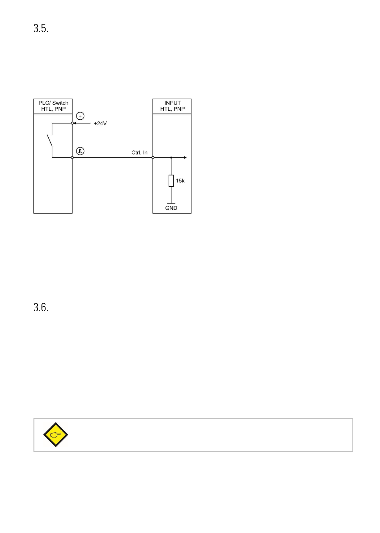
Control Inputs
The three control inputs at terminal 10, 11 and 12 have HTL PNP characteristics.
In the COMMAND MENU the programmable functions for the control inputs can be assigned. Available
functions are: reset the display value, display switching, locking the touch screen or release the lock
function of the control or relay outputs.
Wiring of the control inputs:
Unconnected control inputs are always “LOW”.
All inputs are designed to receive impulses from an electronic impulse source.
Notice for mechanical switching contacts:
When exceptionally mechanical contacts are used, please connect an external capacitor between GND (-)
and the corresponding input (+). A capacity of 10 µF will reduce the input frequency to
20 Hz and miscounting due to contact bouncing will be eliminated.
Analog Output (Option AO/AR)
A 16 bit analog output is available at terminal 13 and 14 / 15
This output can be configured and scaled in the ANALOG MENU.
The following configuration is possible:
• Voltage output: -10 … +10 V
• Current output: 0 … 20 mA
• Current output: 4 … 20 mA
The analog output is proportional to the reference source and is referenced to potential AGND.
AGND and GND are internally interconnected.
Important:
A parallel operation with voltage and current output at the analog output is not allowed.
7788_5150_01a_oi_e.docx / Jan-21 page 13 / 72
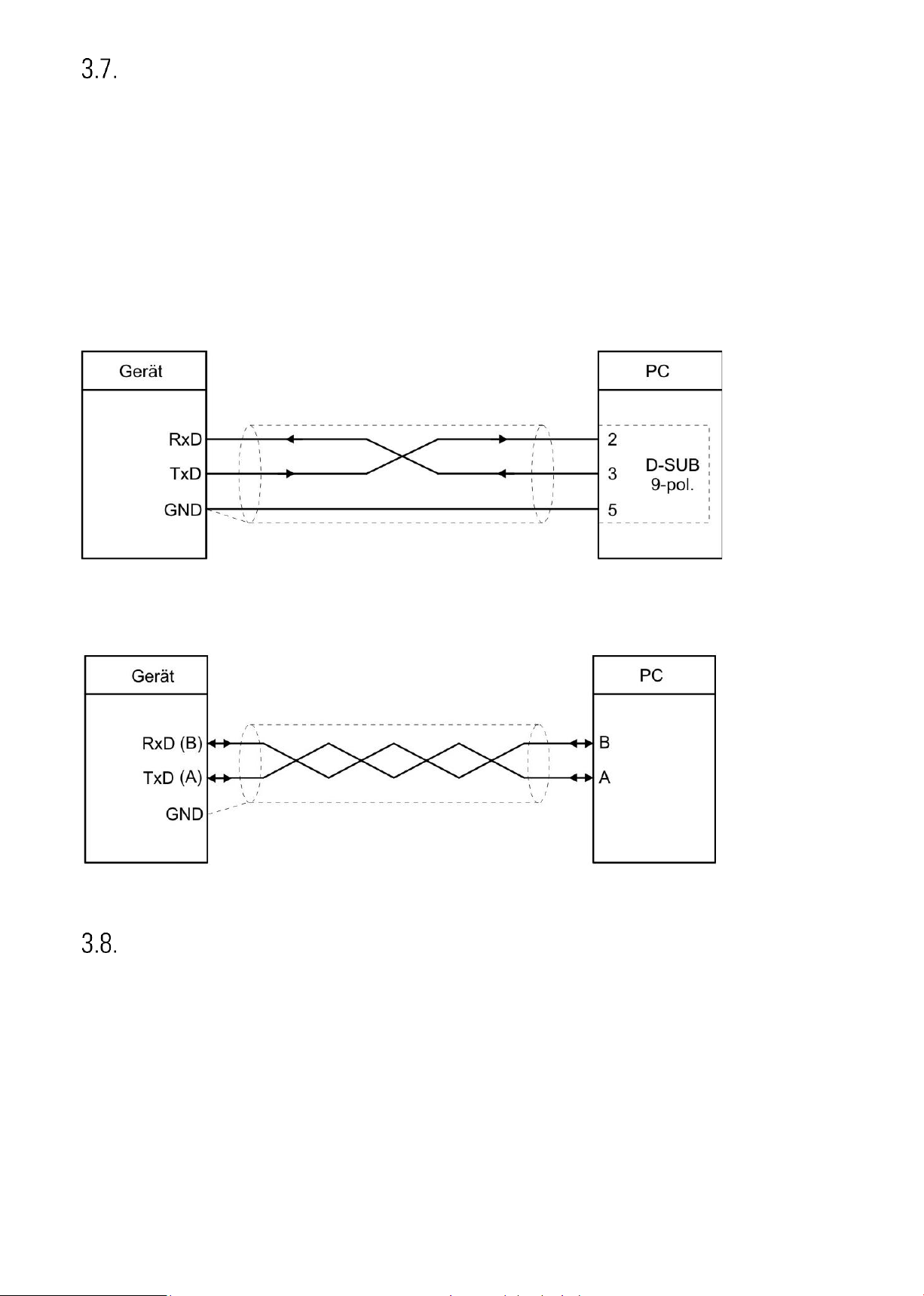
Serial interface (Option AO/AR/CO/CR)
A serial interface (RS232 or RS485) is available at terminal 16, 17 und 18.
This interface can be configured in the SERIAL MENU.
The serial interface RS232 or RS485 can be used:
• for easy setup and commissioning of the units
• to modify settings and parameters during operation
• to read out internal states and actual measuring values by PC or PLC
The following drawing shows the connection to a PC by using a standard Sub-D-9 connector:
Connection of the RS232 interface:
Connection of the RS485 interface:
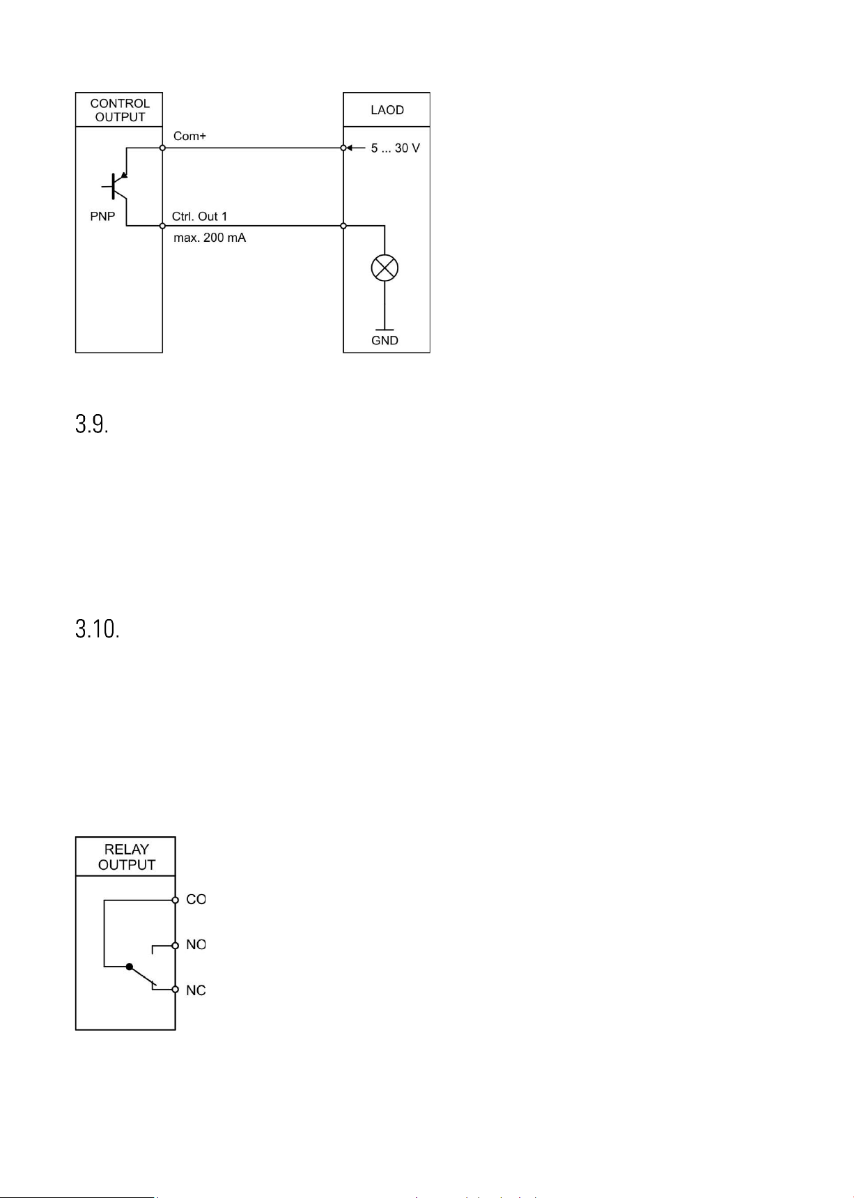
Control-Output (AO/AR/CO/CR)
Four control outputs are available at terminal 20, 21, 22 and 23.
Switching conditions can be set in the PRESELECTION MENU. The output Ctrl. Out1 – 4 are fast PNP
outputs with a switching capability of 5 – 30 Volt / 200 mA per channel. The switching states is displayed
(display with unit and status bar) as C1 … C4.
The switching voltage of the outputs must be applied to input terminal 19 (COM+).
In case of switching inductive loads it is advisable to use external filtering of the coils.
7788_5150_01a_oi_e.docx / Jan-21 page 14 / 72
Wiring of the control-outputs:
AC Power supply (Option AC)
The unit accepts AC supply from 115 to 230 V at the terminals 24 and 25. The power consumption
depends on the level of the supply voltage with aprox. 3VA and the additional current required at the
auxiliary voltage output.
Devices with option AC can also be supplied with a DC voltage between 18 and 30 VDC at terminals 1
and 2.
Relay-Output (Option RL)
Two relay outputs with potential-free changeover contacts are available at terminal 27, 28, 28, 30, 31, 32.
Switching conditions can be set in the PRESELECTION MENU. The switching states are displayed (display
with unit and status bar) as K1 and K4.
AC-switching capacity max. 250 VAC/ max. 3 A / 750 VA
DC-switching capacity max. 150 VAC/ max. 2 A / 50 W
Wiring of the relay outputs
7788_5150_01a_oi_e.docx / Jan-21 page 15 / 72
Display and touch screen
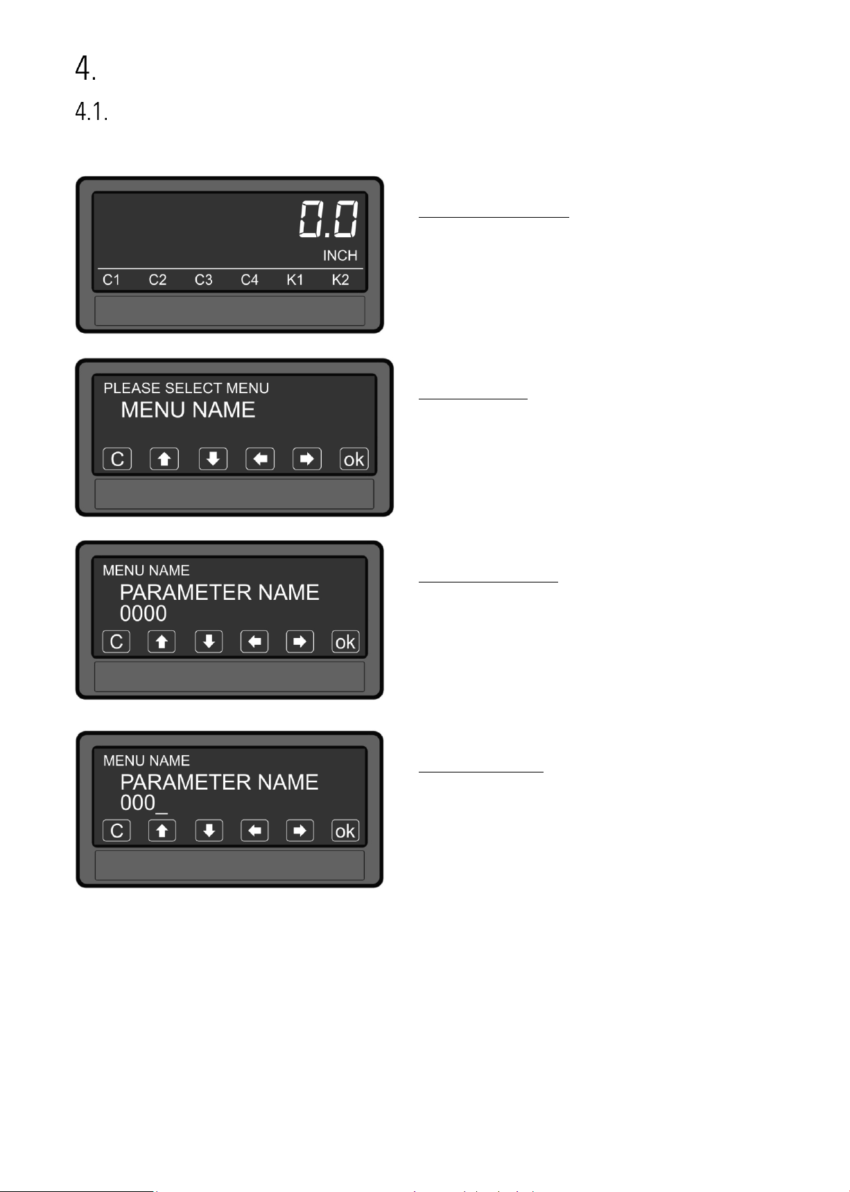
Screen structure for parametrization
The parameter menus and the parameters are described in chapter 5.
Start setup procedure:
To edit the parameters,
press the touchscreen for 3 seconds.
Menu selection:
Select the parameter menu via arrow buttons and
confirm with “OK”.
The menu selection can be terminated
with „C“.
Parameter selection:
Select the parameter via arrow buttons and
confirm with „OK“.
The parameter selection can be terminated with
„C“.
Parameter editing:
Edit the parameter via arrow button up and down,
shift cursor via left and right and save with „OK“.
The parameter editing can be terminated with
„C“.
Parameter changes becomes active only after closing the menu selection.
7788_5150_01a_oi_e.docx / Jan-21 page 16 / 72
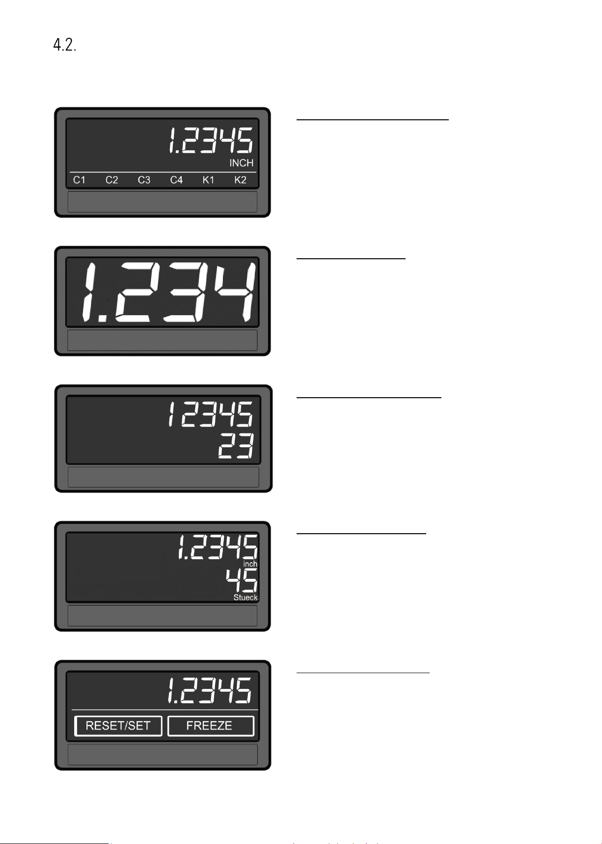
Screen structure in operation
The following screens are available during operation. Depending on the device version and the selected
operation mode, not all displays will be shown.
Display with unit and status bar
To switch to the next display, press the
touch screen.
Control - or Relay status are only shown with
option AO, AR, CO, CR or RL.
Large Display (4 digits)
To switch to the next display, press the top of the
screen.
This is only possible with activated parameter
„LARGE DISPLAY“.
Two-line display without units
To switch to the next display, press the top of the
screen.
Two-line display with units
To switch to the next display, press the top of the
screen.
Display with command keys
To switch to the next display, press the top of the
screen.
7788_5150_01a_oi_e.docx / Jan-21 page 17 / 72
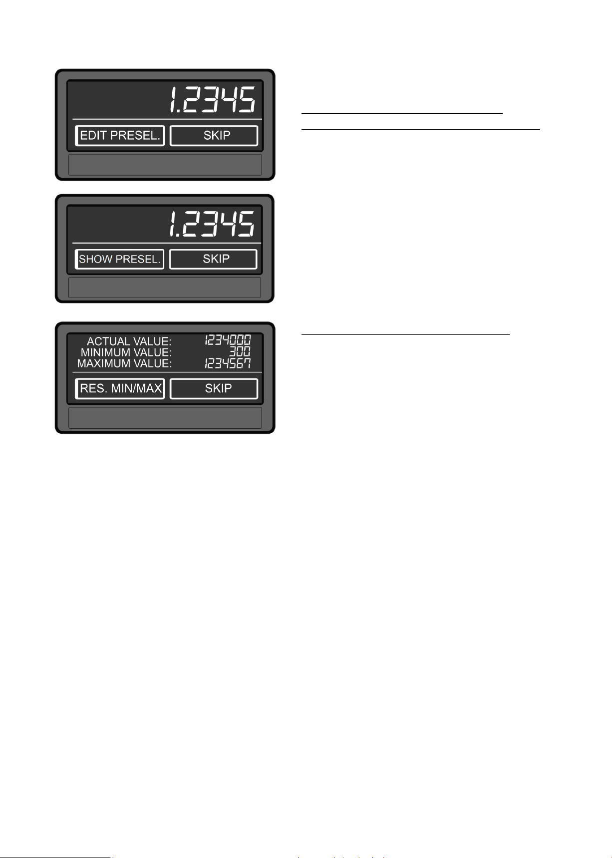
Continuation „Screen structure in operation“:
Display for quick start for enter or display
preselection values (PRESELECTION VALUES 1-4)
The desired command key ("Edit Presel." or "Show
Presel.") can be set in the display menu via the
parameter "QUICKSTART BUTTON".
To switch to the next display, press the top of the
screen or the “skip” button.
This is only possible with option AO, AR, CO, CR
or RL
Display with minimum and maximum value
To switch to the next display, press the top of the
screen or the “skip” button.
The minimum and maximum evaluation refers to
the reference source set in the "SOURCE SINGLE"
parameter.
7788_5150_01a_oi_e.docx / Jan-21 page 18 / 72
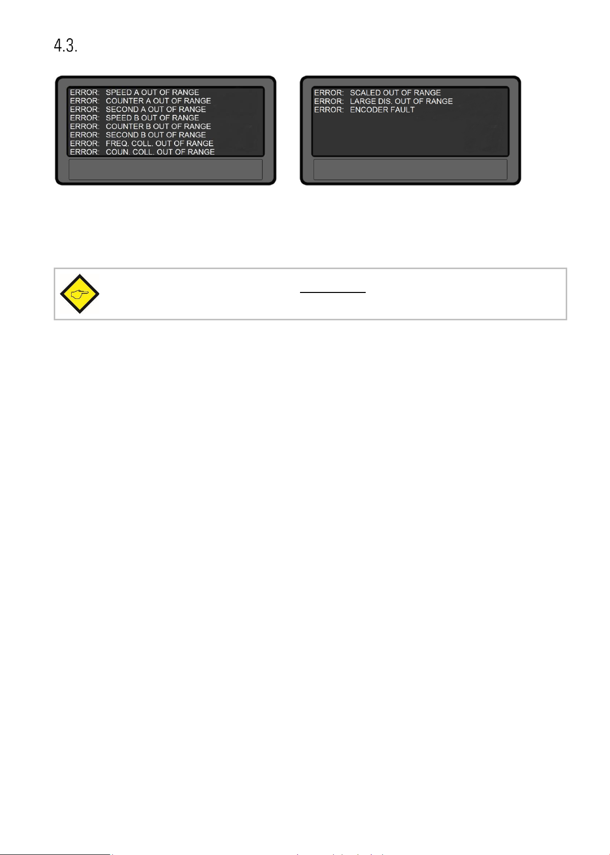
Error messages
If a measurement result, which is shown on the display, is outside the displayable display range, an error
screen is briefly displayed every two seconds. In this appears, which display value was exceeded or
fallen below.
The error messages described are automatically reset as soon as the corresponding
display value is within the representable range.

7788_5150_01a_oi_e.docx / Jan-21 page 19 / 72
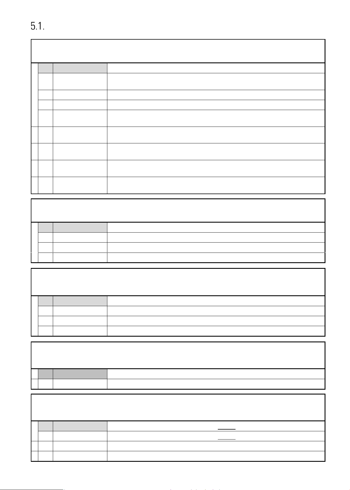
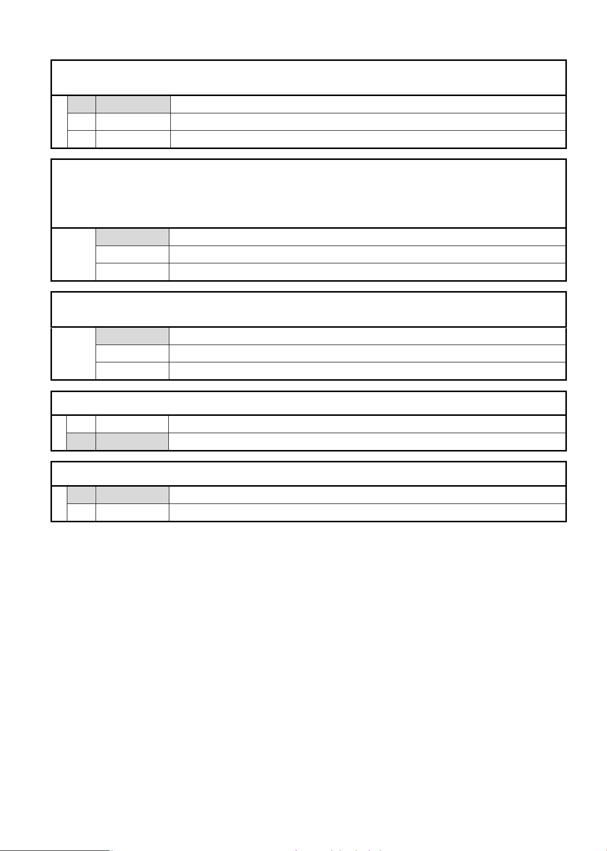
Parameter / Overview-Menu Structure
This section provides an overview of the menus and their parameters. The menu names are printed bold
and the associated parameters are listed under the menu name. Depending on the device version and the
selected operation mode, only the necessary menus / parameters are shown.
Menu / Parameter
GENERAL MENU
OPERATIONAL MODE
ENCODER PROPERTIES
ENCODER SUPPLY
COUNTING DIRECTION
LINEARIZATION MODE
PIN PRESELECTION
PIN PARAMETER
BACK UP MEMORY
FACTORY SETTINGS
SPEED A SETTINGS
DISPLAY VALUE
BASE FREQUENCY
DECIMAL POINT
SAMPLING TIME
WAIT TIME
STANDSTILL TIME
AVERAGE FILTER
SCALE UNITS
SPEED B SETTINGS
DISPLAY VALUE
BASE FREQUENCY
DECIMAL POINT
SAMPLING TIME
WAIT TIME
STANDSTILL TIME
AVERAGE FILTER
SCALE UNITS
Menu / Parameter
COUNTER A SETTINGS
FACTOR
SET VALUE
DECIMAL POINT
SCALE UNITS
SECOND MODE
SECOND SET VALUE
SECOND DECIMAL POINT
SECOND SCALE UNITS
COUNTER B SETTINGS
FACTOR
SET VALUE
DECIMAL POINT
SCALE UNITS
SECOND MODE
SECOND SET VALUE
SECOND DECIMAL POINT
SECOND SCALE UNITS
COLLECTION SETTINGS
DECIMAL POINT FREQUENCY
SCALE UNITS FREQUENCY
DECIMAL POINT COUNTER
SCALE UNITS COUNTER
SCALING SETTINGS
SOURCE
FACTOR
DIVIDER
ADDITIVE VALUE

7788_5150_01a_oi_e.docx / Jan-21 page 20 / 72
Menu / Parameter
PRESELECTION VALUES
PRESELECTION 1
PRESELECTION 2
PRESELECTION 3
PRESELECTION 4
PRESELECTION 1 MENU
SOURCE 1
MODE 1
HYSTERESIS 1
PULSE TIME 1
OUTPUT TARGET 1
OUTPUT POLARITY 1
OUTPUT LOCK 1
START UP DELAY 1
EVENT COLOR 1
PRESELECTION 2 MENU
SOURCE 2
MODE 2
HYSTERESIS 2
PULSE TIME 2
OUTPUT TARGET 2
OUTPUT POLARITY 2
OUTPUT LOCK 2
START UP DELAY 2
EVENT COLOR 2
PRESELECTION 3 MENU
SOURCE 3
MODE 3
HYSTERESIS 3
PULSE TIME 3
OUTPUT TARGET 3
OUTPUT POLARITY 3
OUTPUT LOCK 3
START UP DELAY 3
EVENT COLOR 3
PRESELECTION 4 MENU
SOURCE 4
MODE 4
HYSTERESIS 4
PULSE TIME 4
OUTPUT TARGET 4
OUTPUT POLARITY 4
OUTPUT LOCK 4
START UP DELAY 4
EVENT COLOR 4
Menu / Parameter
SERIAL MENU
UNIT NUMBER
SERIAL BAUD RATE
SERIAL FORMAT
SERIAL INIT
SERIAL PROTOCOL
SERIAL TIMER
SERIAL VALUE
MODBUS
ANALOG MENU
ANALOG SOURCE
ANALOG FORMAT
ANALOG START
ANALOG END
ANALOG GAIN
ANALOG OFFSET
COMMAND MENU
INPUT 1 ACTION
INPUT 1 CONFIG
INPUT 2 ACTION
INPUT 2 CONFIG
INPUT 3 ACTION
INPUT 3 CONFIG
DISPLAY MENU
START DISPLAY
SOURCE SINGLE
SOURCE DUAL TOP
SOURCE DUAL TOWN
LARGE DISPLAY
COLOR
BRIGHTNESS
CONTRAST
SCREEN SAVER
UP-DATE-TIME
FONT
QUICKSTART BUTTON
LINEARISATION MENU
SOURCE
P1(X)
P1(Y)
P2(X)
P2(Y)
…
P23(X)
P23(Y)
P24(X)
P24(Y)
7788_5150_01a_oi_e.docx / Jan-21 page 21 / 72
General Menu
OPERATIONAL MODE
This parameter specifies the selected measuring function.
0
A SINGLE
Input A is the pulse input. (single-channel measurement)
1
A PULSE B DIR
Input A is the pulse input.
Input B determines the direction: for example, "LOW" = forward "HIGH" = backward
2
SUM A+B
Sum: counts impulses A + impulses B and frequency A + frequency B
3
DIF A-B
Difference: counts pulses A - pulses B and frequency A - frequency B
4
RATIO B/A
Ratio: Frequency and counter ratio of both channels (channel B / channel A).
Note: Interpretation of the result with 4 decimal places in the format +/- x.xxxx
5
%-DEVIA B/A
Deviation: percentage deviation from channel B to channel A.
Note: Interpretation of the result with 2 decimal places in the format +/- xxx.xx%
6
A/B 90 x1
Up / down counter for pulses with 2x90 ° offset
(simple edge evaluation x1)
7
A/B 90 x2
Up / down counter for pulses with 2x90 ° offset
(double edge evaluation x1)
8
A/B 90 x4
Up / down counter for pulses with 2x90 ° offset
(fourfold edge evaluation x1)
ENCODER PROPERTIES (for 7788.5150)
This parameter determines the characteristics of the pulse input for 7788.5150.
0
PNP
PNP (switch to +)
1
NPN
NPN (switch to -)
2
NAMUR
Connect sensor (–) to GND and sensor (+) to input (A or B)
3
TRI-STATE
Tri-State for push-pull encoders/ sensors
ENCODER PROPERTIES (for 7788.5155)
This parameter determines the characteristics of the pulse input for 7788.5155.
0
RS422
RS422 standard
1
HTL DIFFERENTIAL
HTL differential
2
HTL PNP
HTL PNP single ended (switch to +)
3
HTL NPN
HTL NPN single ended (switch to -)
ENCODER SUPPLY (only for 7788.5155 available)
This parameter defines the voltage of the auxiliary supply output (Aux-Out).
0
24VDC SUPPLY
24 VDC encoder supply
1
5VDC SUPPLY
5 VDC encoder supply
COUNTING DIRECTION
With this parameter the direction of rotation / direction of counting of the pulse inputs (input A and B) can be
reversed.
0
FOR. A / FOR. B
Direction of rotation / direction of counting of both pulse inputs (A and B) forward
1
REV. A / REV. B
Direction of rotation / direction of counting of both pulse inputs (A and B) reverse
2
FOR. A / REV. B
Direction of rotation / direction of counting input A forward and input B reverse
3
REV. A / FOR. B
Direction of rotation / direction of counting input A reverse and input B forward
7788_5150_01a_oi_e.docx / Jan-21 page 22 / 72
Continuation “General Menu”
LINEARIZATION MODE
This parameter defines the linearization function. See chapter 6.1.
0
OFF
No linearization
1
1 QUADRANT
Linearization in the 1. quadrant
2
4 QUADRANT
Linearization in all 4 quadrants
PIN PRESELECTION
This parameter defines the PIN-code to lock the quick start of the menu PRESELECTION VALUE for entering the
preselection values. (Master PIN 6079).
This Lock function is only useful in conjunction with active lock function in PIN PARAMETER.
0000
No lock
…
9999
Access after entering PIN-Code 9999
PIN PARAMETER
This parameter defines the PIN-code for lock function of all parameters (master PIN 6079).
0000
No lock
… 9999
Parameterization of the unit after entering PIN-code 9999
BACK UP MEMORY
0
NO
No back memory –up by power failure
1
YES
Backup memory by power failure, actual value will be saved
FACTORY SETTINGS
0
NO
No default values are loaded
1
YES
Load default values of all parameters (grey marked default values)

7788_5150_01a_oi_e.docx / Jan-21 page 23 / 72
Speed A Settings
In this menu, the settings for a frequency measurement / tachometer on channel A are defined.
Depending on the operating mode selected, only input A or input A and input B with 90 ° phase offset are
active for forward / reverse direction detection.
DISPLAY VALUE
Desired value, which should be displayed at the setting of BASE FREQUENCY.
1
Smallest value
1000
Default value
99999999
Highest value
BASE FREQUENCY (HZ)
Reference frequency for the desired DISPLAY VALUE.
1
Smallest value
100
Default value
500000
Highest value
DECIMAL POINT
This value defines the position of the decimal point.
0
NO
No decimal point
1
0000000.0
Decimal point at the specified position
2
000000.00
Decimal point at the specified position
3
00000.000
Decimal point at the specified position
4
0000.0000
Decimal point at the specified position
5
000.00000
Decimal point at the specified position
6
00.000000
Decimal point at the specified position
7
0.0000000
Decimal point at the specified position
SAMPLING TIME (S)
The configured value corresponds to the minimum measurement time. The Parameter is used as a filter in case
of irregular frequencies. This parameter directly affects the response time of the unit.
0.005
Shortest Sampling time
0.1
Default value
9.999
Longest Sampling time

7788_5150_01a_oi_e.docx / Jan-21 page 24 / 72
Continuation “Speed A Settings“:
WAIT TIME (S)
This parameter defines the period time of the lowest frequency, accordingly the time between two rising signal
edges on channel A detecting frequency 0 Hz. Frequencies with a period time higher than the set “WAIT TIME 1”
will be detected as frequency = 0 Hz.
0.01
Frequency = 0 Hz, for frequencies below 100 Hz
1.00
Default value
80.00
Frequency = 0 Hz, for frequencies below 0,01 Hz
STANDSTILL TIME (S)
This parameter defines the time setting for standstill definition. A time of xx.xx seconds after detection "
frequency = 0 Hz " the unit signals "standstill" and reactivates the start-up-delays.
Stand still detection can be set in PRESELECT MENU.
0.00
Shortest time
…
99.99
Largest time
AVERAGE FILTER
Selectable average or filter function to avoid measuring fluctuations by unstable frequencies. At setting 1 to 4 a
floating average calculation is performed. At settings 5 to 8, the device uses an exponential filter. The time
constant T (63%) corresponds to the sampling cycles.
For example: If SAMPLING TIME = 0,1 s and AVERAGE FILTER = Exponential filter, T (63 %) = 2x SAMPLING
TIME, after 0,2 seconds, 63% of the step size are reached
0
No average value will be created
1
2 numbers of floating average cycles
2
4 numbers of floating average cycles
3
8 numbers of floating average cycles
4
16 numbers of floating average cycles
5
Exponential filter, T (63 %) = 2x SAMPLING TIME
6
Exponential filter, T (63 %) = 4x SAMPLING TIME
7
Exponential filter, T (63 %) = 8x SAMPLING TIME
8
Exponential filter, T (63 %) = 16x SAMPLING TIME

7788_5150_01a_oi_e.docx / Jan-21 page 25 / 72
Continuation “Speed A Settings“:
SCALE UNITS
This parameter defines the required engineering unit. This parameter does not affect the calculation of the display value. The
number of decimal places must be defined with the parameter DECIMAL POINT
0
Hz
Default
1
kHz 2
m/s 3
m/min
4 km/h 5
mph 6
1/min
7 RPM
8
1/sec
9
RPS 10
Stk/h
11
pcs/h
12
mm 13 m
14
inch
15
feet
16
Stueck
17
pcs 18
sec 19
min 20
Min:Sec
21
H:M:S
22
Min:Sec:00
23
l/min
24
gal/min
25
ml/min
26
gr/min
27
inch/min
28
H:M
29
Edit Unit
A customized unit with up to 16 digits can be edited using this parameter.
Pressing the "OK" button opens the Edit Unit Menu.
A unit can be created using the arrow keys. (by pressing and holding the arrow keys the
characters scroll fast).
The “OK” butten saves the Edit Unit Menu. The “C” button closes the Edit Unit Menu.
! " # $ % & ' ( ) * + , - . / 0 1 2 3 4 5 6 7 8 9 : ; < = >
?
@ A B C D E F G H I J K L M N O P Q R S T U V W X Y Z [ \ ] ^
_
` a b c d e f g h i j k l m n o p q r s t u v w x y z { | } ~

7788_5150_01a_oi_e.docx / Jan-21 page 26 / 72
Speed B Settings
In this menu, the settings for a frequency measurement / tachometer on channel B are defined.
This menu is only displayed if the corresponding OPERATIONAL MODE is selected in the GENERAL
MENU. (e.g., "SUM A + B", "DIF A-B", "RATIO B / A", or "% DEVIA B / A")
DISPLAY VALUE
Desired value, which should be displayed at the setting of BASE FREQUENCY.
1
Smallest value
1000
Default value
99999999
Highest value
BASE FREQUENCY (HZ)
Reference frequency for the desired DISPLAY VALUE.
1
Smallest value
100
Default value
500000
Highest value
DECIMAL POINT
This value defines the position of the decimal point.
0
NO
No decimal point
1
0000000.0
Decimal point at the specified position
2
000000.00
Decimal point at the specified position
3
00000.000
Decimal point at the specified position
4
0000.0000
Decimal point at the specified position
5
000.00000
Decimal point at the specified position
6
00.000000
Decimal point at the specified position
7
0.0000000
Decimal point at the specified position
SAMPLING TIME (S)
The configured value corresponds to the minimum measurement time. The Parameter is used as a filter in case
of irregular frequencies. This parameter directly affects the response time of the unit.
0.005
Shortest Sampling time
0.1
Default value
9.999
Longest Sampling time

7788_5150_01a_oi_e.docx / Jan-21 page 27 / 72
Continuation “Speed B Settings“:
WAIT TIME (S)
This parameter defines the period time of the lowest frequency, accordingly the time between two rising signal
edges on channel B detecting frequency 0 Hz. Frequencies with a period time higher than the set “WAIT TIME 1”
will be detected as frequency = 0 Hz.
0.01
Frequency = 0 Hz, for frequencies below 100 Hz
1.00
Default value
80.00
Frequency = 0 Hz, for frequencies below 0,01 Hz
STANDSTILL TIME (S)
This parameter defines the time setting for standstill definition. A time of xx.xx seconds after detection "
frequency = 0 Hz " the unit signals "standstill" and reactivates the start-up-delays.
Stand still detection can be set in PRESELECT MENU.
0.00
Shortest time
…
99.99
Largest time
AVERAGE FILTER
Selectable average or filter function to avoid measuring fluctuations by unstable frequencies. At setting 1 to 4 a
floating average calculation is performed. At settings 5 to 8, the device uses an exponential filter. The time
constant T (63%) corresponds to the sampling cycles.
For example: If SAMPLING TIME = 0,1 s and AVERAGE FILTER = Exponential filter, T (63 %) = 2x SAMPLING
TIME, after 0,2 seconds, 63% of the step size are reached
0
No average value will be created
1
2 numbers of floating average cycles
2
4 numbers of floating average cycles
3
8 numbers of floating average cycles
4
16 numbers of floating average cycles
5
Exponential filter, T (63 %) = 2x SAMPLING TIME
6
Exponential filter, T (63 %) = 4x SAMPLING TIME
7
Exponential filter, T (63 %) = 8x SAMPLING TIME
8
Exponential filter, T (63 %) = 16x SAMPLING TIME

7788_5150_01a_oi_e.docx / Jan-21 page 28 / 72
Continuation “Speed B Settings“:
SCALE UNITS (display unit of measurement)
This parameter determines which unit is shown on the display. Setting the SCALE UNITS does not affect the display
value. The decimal point is set in the parameter DECIMAL POINT.
A list of possible units can be found in "SPEED A SETTINGS - SCALE UNITS".

7788_5150_01a_oi_e.docx / Jan-21 page 29 / 72
Counter A Settings
In this menu, the settings for the pulse counter (or position indicator) on channel A are defined.
FACTOR
Scaling factor for channel A.
For example: A setting of factor 1.23456 and 100000 input pulses will result in a value of 123456.
0,00001
Smallest value
1
Default value
99,99999
Highest value
SET VALUE
In case of a set/reset command (via keys, Control-Inputs or PC-user interface), the counter of channel A is set to
the value entered here.
-99999999
Smallest value
0
Default value
+99999999
Highest value
DECIMAL POINT
This value defines the position of the decimal point.
0
NO
No decimal point
1
0000000.0
Decimal point at the specified position
2
000000.00
Decimal point at the specified position
3
00000.000
Decimal point at the specified position
4
0000.0000
Decimal point at the specified position
5
000.00000
Decimal point at the specified position
6
00.000000
Decimal point at the specified position
7
0.0000000
Decimal point at the specified position

7788_5150_01a_oi_e.docx / Jan-21 page 30 / 72
Continuation “Counter A Settings“:
SCALE UNITS
This parameter defines the required engineering unit. This parameter does not affect the calculation of the display value. The
number of decimal places must be defined with the parameter DECIMAL POINT
0
Hz 1
kHz 2
m/s 3
m/min
4 km/h 5
mph 6
1/min
7 RPM
8
1/sec
9
RPS 10
Stk/h
11
pcs/h
12
mm
Default
13 m
14
inch
15
feet
16
Stueck
17
pcs 18
sec 19
min 20
Min:Sec
21
H:M:S
22
Min:Sec:00
23
l/min
24
gal/min
25
ml/min
26
gr/min
27
inch/min
28
H:M
29
Edit Unit
A customized unit with up to 16 digits can be edited using this parameter.
Pressing the "OK" button opens the Edit Unit Menu.
A unit can be created using the arrow keys. (by pressing and holding the arrow keys the
characters scroll fast).
The “OK” butten saves the Edit Unit Menu. The “C” button closes the Edit Unit Menu.
! " # $ % & ' ( ) * + , - . / 0 1 2 3 4 5 6 7 8 9 : ; < = >
?
@ A B C D E F G H I J K L M N O P Q R S T U V W X Y Z [ \ ] ^
_
` a b c d e f g h i j k l m n o p q r s t u v w x y z { | } ~

7788_5150_01a_oi_e.docx / Jan-21 page 31 / 72
Continuation “Counter A Settings“:
SECOND MODE
Setting of the batch counter / total counter.
The function of batch counting according to a preset value is only possible in combination with the switch
condition “automatic reset to zero” (RESULT <= PRES-> 0), “automatic reset to set value” (RESULT>=PRES-
>VALUE) or “set the counter value to the respective preselection value” (RESULT <=0-> SET).
When SECOND MODE is active, PRESELECTION serves as the present value (SOURCE 1-4) for the SECOND
COUNTER A.
Example for the batch counter:
If the batch counter should increment 1 all 1000 pulses, the value e.g. PRESELCTION 1 has to be set to 1000, the
related reference source SOURCE 1 to “COUNTER A”, the corresponding switching condition MODE 1 to
"RESULT>=PRES->0" and SECOND MODE to INCREMENT BATCH. Should an output be turned on after a batch
amount of 33, e.g. PRESELECTION 2 has to be set to 33, the related reference source SOURCE 2 to “SECOND
COUNTER A” and the switching condition of MODE 2 has to be set to display value greater than or equal
(RESUL>=PRES).
Example for the total counter:
For the total counter, SECOND MODE must be set to “TOTAL COUNTER”. The total counter counts here parallel to
the main counter. e.g. If the total counter should automatically reset to 0, when 4000 is reached, the preset value
e.g. PRESELECTION 3 must be set to “4000”, the reference source SOURCE 3 must be set to
“SECOND COUNTER A” and the corresponding switching condition MODE 3 must be set to "RESULT> = PRES-> 0"
0
OFF
No batch counter and no total counter
1
INCREMENT BATCH
increment batch counter
2
DECREMENT BATCH
decrement batch counter
3
USE INPUTS ONLY
increment / decrement batch counter only by external commands
(see command menu)
4
TOTAL COUNTER
Total counter is activated
SECOND SET VALUE
With a "RESET / SET " command (command “SET SECOND A” via control input), the Second Counter A (batch
counter / total counter) is set to this value.
(Parameter only visible with activated "SECOND MODE")
-99999999
Smallest value
0
Default value
+99999999
Highest value
SECOND DECIMAL POINT
This value defines the position of the decimal point.
(Parameter only visible with activated "SECOND MODE")
0
NO
No decimal point
1
0000000.0
Decimal point at the specified position
2
000000.00
Decimal point at the specified position
3
00000.000
Decimal point at the specified position
4
0000.0000
Decimal point at the specified position
5
000.00000
Decimal point at the specified position
6
00.000000
Decimal point at the specified position
7
0.0000000
Decimal point at the specified position

7788_5150_01a_oi_e.docx / Jan-21 page 32 / 72
Continuation “Counter A Settings“:
SECOND SCALE UNITS (display unit of measurement)
This parameter determines which unit is shown on the display. Setting the SCALE UNITS does not affect the display
value. The decimal point is set in the parameter SECOND DECIMAL POINT.
A list of possible units can be found in "COUNTER A SETTINGS - SCALE UNITS".
(Parameter only visible with activated "SECOND MODE")

7788_5150_01a_oi_e.docx / Jan-21 page 33 / 72
Counter B Settings
In this menu, the settings for the pulse counter (or position indicator) on channel B are defined.
This menu is only displayed when the appropriate OPERATIONAL MODE in the GENERAL MENU is
selected (e.g., "SUM A + B", "DIF A-B", "RATIO B / A", or "% DEVIA B / A").
FACTOR
Scaling factor for channel B.
For example: A setting of factor 1.23456 and 100000 input pulses will result in a value of 123456.
0,00001
Smallest value
1
Default value
99,99999
Highest value
SET VALUE
In case of a set/reset command (via keys, Control-Inputs or PC-user interface), the counter of channel A is set to
the value entered here
-99999999
Smallest value
0
Default value
+99999999
Highest value
DECIMAL POINT
This value defines the position of the decimal point.
0
NO
No decimal point
1
0000000.0
Decimal point at the specified position
2
000000.00
Decimal point at the specified position
3
00000.000
Decimal point at the specified position
4
0000.0000
Decimal point at the specified position
5
000.00000
Decimal point at the specified position
6
00.000000
Decimal point at the specified position
7
0.0000000
Decimal point at the specified position
SCALE UNITS (display unit of measurement)
This parameter determines which unit is shown on the display. Setting the SCALE UNITS does not affect the
display value. The decimal point is set in the parameter DECIMAL POINT.
A list of possible units can be found in "COUNTER A SETTINGS - SCALE UNITS".

7788_5150_01a_oi_e.docx / Jan-21 page 34 / 72
Continuation “Counter B Settings“:
SECOND MODE
Setting of the batch counter / total counter.
The function of batch counting according to a preset value is only possible in combination with the switch
condition “automatic reset to zero” (RESULT <= PRES-> 0), “automatic reset to set value” (RESULT>=PRES>VALUE) or “set the counter value to the respective preselection value” (RESULT <=0-> SET).
When SECOND MODE is active, PRESELECTION serves as the present value (SOURCE 1-4) for the SECOND
COUNTER B.
Example for the batch counter:
If the batch counter should increment 1 all 1000 pulses, the value e.g. PRESELCTION 1 has to be set to 1000, the
related reference source SOURCE 1 to “COUNTER B”, the corresponding switching condition MODE 1 to
"RESULT>=PRES->0" and SECOND MODE to INCREMENT BATCH. Should an output be turned on after a batch
amount of 33, e.g. PRESELECTION 2 has to be set to 33, the related reference source SOURCE 2 to “SECOND
COUNTER B” and the switching condition of MODE 2 has to be set to display value greater than or equal
(RESUL>=PRES).
Example for the total counter:
For the total counter, SECOND MODE must be set to “TOTAL COUNTER”. The total counter counts here parallel to
the main counter. e.g. If the total counter should automatically reset to 0, when 4000 is reached, the preset value
e.g. PRESELECTION 3 must be set to “4000”, the reference source SOURCE 3 must be set to
“SECOND COUNTER B” and the corresponding switching condition MODE 3 must be set to "RESULT> = PRES-> 0"
0
OFF
No batch counter and no total counter
1
INCREMENT BATCH
increment batch counter
2
DECREMENT BATCH
decrement batch counter
3
USE INPUTS ONLY
increment / decrement batch counter only by external commands
(see command menu)
4
TOTAL COUNTER
Total counter is activated
SECOND SET VALUE
With a "RESET / SET " command (command “SET SECOND B” via control input), the Second Counter B (batch
counter / total counter) is set to this value.
(Parameter only visible with activated "SECOND MODE")
-99999999
Smallest value
0
Default value
+99999999
Highest value
SECOND DECIMAL POINT
This value defines the position of the decimal point.
(Parameter only visible with activated "SECOND MODE")
0
NO
No decimal point
1
0000000.0
Decimal point at the specified position
2
000000.00
Decimal point at the specified position
3
00000.000
Decimal point at the specified position
4
0000.0000
Decimal point at the specified position
5
000.00000
Decimal point at the specified position
6
00.000000
Decimal point at the specified position
7
0.0000000
Decimal point at the specified position

7788_5150_01a_oi_e.docx / Jan-21 page 35 / 72
Continuation „Counter B Settings“:
SECOND SCALE UNITS (display unit of measurement)
This parameter determines which unit is shown on the display. Setting the SCALE UNITS does not affect the display
value.The number of decimal places must be defined with the parameter SECOND DECIMAL POINT.
A list of possible units can be found in "COUNTER A SETTINGS - SCALE UNITS".
(Parameter only visible with activated "SECOND MODE")

7788_5150_01a_oi_e.docx / Jan-21 page 36 / 72
Collection Settings
In this menu the decimal point as well as the corresponding unit for the linked results ("Frequency
Collection" and "Counter Collection") can be set. This menu is only displayed if the corresponding
OPERATIONAL MODE is selected in the GENERAL MENU. (e.g., "SUM A + B", "DIF A-B", "RATIO B / A", or
"% DEVIA B / A")
DECIMAL POINT FREQUENCY
This value defines the position of the decimal point
0
NO
No decimal point
1
0000000.0
Decimal point at the specified position
2
000000.00
Decimal point at the specified position
3
00000.000
Decimal point at the specified position
4
0000.0000
Decimal point at the specified position
5
000.00000
Decimal point at the specified position
6
00.000000
Decimal point at the specified position
7
0.0000000
Decimal point at the specified position
SCALE UNITS FREQUENCY (display unit of measurement)
This parameter determines which unit is shown on the display. Setting the SCALE UNITS does not affect the display
value. The decimal point is set in the parameter DECIMAL POINT.
A list of possible units can be found in "SPEED A SETTINGS - SCALE UNITS".
DECIMAL POINT COUNTER
This value defines the position of the decimal point
0
NO
No decimal point
1
0000000.0
Decimal point at the specified position
2
000000.00
Decimal point at the specified position
3
00000.000
Decimal point at the specified position
4
0000.0000
Decimal point at the specified position
5
000.00000
Decimal point at the specified position
6
00.000000
Decimal point at the specified position
7
0.0000000
Decimal point at the specified position
SCALE UNITS COUNTER (display unit of measurement)
This parameter determines which unit is shown on the display. Setting the SCALE UNITS does not affect the display
value. The decimal point is set in the parameter DECIMAL POINT.
A list of possible units can be found in "SPEED A SETTINGS - SCALE UNITS".

7788_5150_01a_oi_e.docx / Jan-21 page 37 / 72
Scaling Settings
In this menu, additional scaling factors can be defined with which the desired process value is
additionally calculated again. The correspondingly scaled result is stored in the "SCALED RESULT" and
can be selected accordingly for further processing by means of an adjustable reference source. (eg via
"Source" parameter for analogue output, switching output, display, ...)
SOURCE (reference source)
This parameter defines the reference source, which is additionally calculated with the scaling factors
0
SPEED A
Result of frequency measurement on channel A (or A / B 90)
1
COUNTER A
Result of the counter on channel A (or A / B 90)
2
SECOND COUNTER A
Result of the second counter (total counter / batch counter) on channel A
(or A / B 90)
(Only visible if "Second Mode -A" has been activated.)
3
SPEED B
Result of frequency measurement on channel B
(Only visible if corresponding "Operational Mode" has been activated.)
4
COUNTER B
Result of the counter on channel B
(Only visible if corresponding "Operational Mode" has been activated.)
5
SECOND COUNTER B
Result of the second counter (total counter / batch counter) on channel B
(Only visible if "Second Mode -B" has been activated.)
6
FREQUENCY COLL.
Result of the linked frequency of channel A and B (A + B, A-B, B / A, ...)
(Only visible if corresponding "Operational Mode" has been activated.)
7
COUNTER COLL.
Result of the linked counters of channel A and B (A + B, A-B, B / A, ...)
(Only visible if corresponding "Operational Mode" has been activated.)
FACTOR
This parameter defines the factor
-99999999
Smallest value
1
Default value
99999999
Highest value
DIVIDER
This parameter defines the divisor.
-99999999
Smallest value
1
Default value
99999999
Highest value
ADDITIVE VALUE
This parameter defines an additive constant.
-99999999
Smallest value
0
Default value
99999999
Highest value

7788_5150_01a_oi_e.docx / Jan-21 page 38 / 72
Preselection Values
In this menu, the preselection values or switching points are set. The preselection values always refer to
the SOURCE selected in the PRESELECTION MENU.
This feature is only available on devices with option CO, CR, AO, AR or RL.
PRESELECTION 1
Preselection / switching point 1
-99999999
Smallest value
1000
Default value
+99999999
Highest value
PRESELECTION 2
Preselection / switching point 2
-99999999
Smallest value
2000
Default value
+99999999
Highest value
PRESELECTION 3
Preselection / switching point 3
-99999999
Smallest value
3000
Default value
+99999999
Highest value
PRESELECTION 4
Preselection / switching point 4
-99999999
Smallest value
4000
Default value
+99999999
Highest value

7788_5150_01a_oi_e.docx / Jan-21 page 39 / 72
Preselection 1 Menu
In this menu, the parameters of the reference source, the switching conditions and further definitions for
preselection value / switching point 1 are defined.
This function is only available for devices with option CO, CR, AO, AR or RL.
SOURCE (reference source)
This parameter defines the reference source, which is additionally calculated with the scaling factors
0
SPEED A
Result of frequency measurement on channel A (or A / B 90)
1
COUNTER A
Result of the counter on channel A (or A / B 90)
2
SECOND COUNTER A
Result of the second counter (total counter / batch counter) on channel A
(or A / B 90)
(Only visible if "Second Mode -A" has been activated.)
3
SPEED B
Result of frequency measurement on channel B
(Only visible if corresponding "Operational Mode" has been activated.)
4
COUNTER B
Result of the counter on channel B
(Only visible if corresponding "Operational Mode" has been activated.)
5
SECOND COUNTER B
Result of the second counter (total counter / batch counter) on channel B
(Only visible if "Second Mode -B" has been activated.)
6
FREQUENCY COLL.
Result of the linked frequency of channel A and B (A + B, A-B, B / A, ...)
(Only visible if corresponding "Operational Mode" has been activated.)
7
COUNTER COLL.
Result of the linked counters of channel A and B (A + B, A-B, B / A, ...)
(Only visible if corresponding "Operational Mode" has been activated.)
8
SCALED RESULT
Result of the additionally scaled process value

7788_5150_01a_oi_e.docx / Jan-21 page 40 / 72
Continuation „PRESELECTION 1 MENU“:
MODE 1
Switching conditions for preselection 1. Output/ relay/ display switches under the following conditions:
0
|RESULT|>=|PRES|
Absolute value of the display value is greater or equal absolute value of
PRESELECTION 1
With HYSTERESIS 1 not equal 0 the following switching condition is applied:
Display value >= PRESELECTION 1 → ON,
Display value < PRESELECTION 1 – HYSTERESIS 1 →OFF
1
|RESULT|<=|PRES|
Absolute value of the display value is less or equal absolute value of
PRESELECTION 1 (start-up suppression (START UP DELAY) is advisable)
With HYSTERESIS 1 not equal 0 the following switching condition is applied:
Display value <= PRESELECTION 1 → ON,
Display value > PRESELECTION 1 + HYSTERESIS 1 →OFF
2
|RESULT|=|PRES|
Absolute value of the display value is equal absolute value of PRESELECTION 1
A range (Preselection +/- ½ Hysteresis) can be defined and monitored in
conjunction with the hysteresis.
With HYSTERESIS 1 not equal 0 the following switching condition is applied:
Display value > PRESELECTION 1 + ½ HYSTERESIS 1 → OFF,
Display value < PRESELECTION 1 - ½ HYSTERESIS 1 → OFF
3
RESULT>=PRES
Display value is greater or equal PRESELECTION 1, e.g. overspeed
With HYSTERESIS 1 not equal 0 the following switching condition is applied:
Display value >= PRESELECTION 1 → ON,
Display value < PRESELECTION 1 – HYSTERESIS 1 →OFF
4
RESULT<=PRES
Display value is less or equal PRESELECTION 1, e.g. underspeed
(start-up suppression “START UP DELAY” is recommend)
With HYSTERESIS 1 not equal 0 the following switching condition is applied:
Display value <= PRESELECTION 1 → ON,
Display value > PRESELECTION 1 + HYSTERESIS 1 →OFF
5
RESULT=PRES
Display value is equal PRESELECTION 1. A range (Preselection +/- ½ Hysteresis)
can be defined and monitored in conjunction with the hysteresis.
With HYSTERESIS 1 not equal 0 the following switching condition is applied:
Display value > PRESELECTION 1 + ½ HYSTERESIS 1 → OFF,
Display value < PRESELECTION 1 - ½ HYSTERESIS 1 → OFF
6
RESULT=0
Display value is zero (Standstill after STANDSTILL TIME(s)),
e. g. standstill monitoring (only for reference source SPEED A and SPEED B).
7
RESULT>= PRES->0
Auto reset to zero: (only for reference sources: COUNTER A, SECOND COUNTER A,
COUNTER B and SECOND COUNTER B)
Display value is greater or equal PRESELECTION 1, the display value is set to zero.
If the BATCH MODE A or B is active, the corresponding batch counter increments
or decrements when the display value is set to zero and when the corresponding
reference source COUNTER A or COUNTER B was selected.
8
RESULT<= 0->SET
Auto set to PRESELECTION 1: (only for reference sources: COUNTER A, SECOND
COUNTER A, COUNTER B and SECOND COUNTER B)
Display value is less or equal zero, the display value is set to PRESELECTION 1.
If the BATCH MODE A or B is active, the corresponding batch counter increments
or decrements when PRESELECTION 1 is set and when the corresponding
reference source COUNTER A or COUNTER B was selected.
9
RES>=PRES-TRAIL
Trailing PRESELECTION 1:
Display value is greater or equal PRESELECTION 2 – PRESELECTION 1 → ON,
PRESELECTION 1 is the trailing value from PRESELECTION 2

7788_5150_01a_oi_e.docx / Jan-21 page 41 / 72
Continuation „PRESELECTION 1 MENU“:
10
RESULT>= PRES->VALUE
Set the counter reading to “SET VALUE”: (only for reference sources:
COUNTER A, SECOND COUNTER A, COUNTER B and SECOND COUNTER B)
Display value is greater or equal PRESELECTION 1, the counter reading is
set to the corresponding “SET VALUE”.
If the BATCH MODE A or B is active, the corresponding batch counter
increments or decrements when the counter reading is set to the
corresponding “SET VALUE” and when the corresponding reference source
COUNTER A or COUNTER B was selected.
11
ERROR SET
Error message for device errors
HYSTERESIS 1
This parameter defines the switching hysteresis of the switch-off point for preselection 1
0
No switching hysteresis
… 9999
Switching hysteresis of 99999
PULSE TIME 1 (S)
Duration of output pulse for the switching condition of preselection 1
0.000
No output pulse (static signal)
…
60.000
Pulse duration of 60 seconds
OUTPUT TARGET 1
Assignment of an output or relay for the switching condition of preselection 1.
If more than one switching condition is assigned to one output / relay, the output is set when at least one
switching condition is true
0
NO
No assignment
1
CTRL OUT 1
Switching condition assigned to “Ctrl. Out 1”
2
CTRL OUT 2
Switching condition assigned to “Ctrl. Out 2”
3
CTRL OUT 3
Switching condition assigned to “Ctrl. Out 3”
4
CTRL OUT 4
Switching condition assigned to “Ctrl. Out 4”
5
RELAY 1
Switching condition assigned to “Rel. 1”
6
RELAY 2
Switching condition assigned to “Rel. 2”
OUTPUT POLARITY 1
Polarity for the switching condition of preselection 1
0
ACTIVE HIGH
Switching condition is true → Active „HIGH“
1
ACTIVE LOW
Switching condition is true → Active „LOW“
OUTPUT LOCK 1
Latch for the switching condition of preselection 1
0
NO
No latch for preselection
1
YES
Latch for preselection (command LOCK RELEASE will clear latch)

7788_5150_01a_oi_e.docx / Jan-21 page 42 / 72
Continuation „PRESELECTION 1 MENU“:
START UP DELAY 1 (S)
Start-up suppression for the switching condition of preselection 1.
This adjustment is only valid for the switching condition |RESULT|<=|PRES| or RESULT<=PRES and only for
reference sources “SPEED A” and “SPEED B”.
(Start Up Delay 3 and 4 have an automatic start up suppression).
00.000
No start-up suppression
…
60.000
Start-up suppression in seconds
EVENT COLOR 1
Event-depending change of the display color for the switching condition of preselection 1.
EVENT COLOR 1 has the lowest priority. EVENT COLOR 2 … 4 are allowed to overwrite this color change.
0
NO CHANGE
No color change.
1
CHANGE TO RED
Color change to red
2
CHANGE TO GREEN
Color change to green
3
CHANGE TO YELLOW
Color change to yellow

7788_5150_01a_oi_e.docx / Jan-21 page 43 / 72
Preselection 2 Menu
SOURCE 2
The reference source for PRESELECTION 2, see PRESELECTION 1 MENU.
MODE 2
Switching conditions for preselection 2. Output/ relay/ display switches under the following conditions:
See chapter PRESELECTION 1 MENU
9
RES>=PRESTRAIL
Trailing preselection 2:
Display value is greater or equal to PRESELECTION 1 – PRESELECTION 2 → ON,
PRESELECTION 2 is the trailing preselection from PRESELECTION 1.
HYSTERESIS 2
This parameter defines the switching hysteresis of the switch-off point for preselection 2.
See chapter PRESELECTION 1 MENU.
PULSE TIME 2 (S)
Duration of output pulse for the switching condition of preselection 2.
See chapter PRESELECTION 1 MENU.
OUTPUT TARGET 2
Assignment of an output or relay for the switching condition of preselection 2.
See chapter PRESELECTION 1 MENU.
OUTPUT POLARITY 2
Polarity for the switching condition of preselection 2.
See chapter PRESELECTION 1 MENU.
OUTPUT LOCK 2
Latch for the switching condition of preselection 2.
See chapter PRESELECTION 1 MENU.
START UP DELAY 2 (S)
Start-up suppression for the switching condition of preselection 2.
See chapter PRESELECTION 1 MENU.
(Start Up Delay 3 and 4 have an automatic start up suppression).
EVENT COLOR 2
Event-depending change of the display color for the switching condition of preselection 2.
See chapter PRESELECTION 1 MENU.

7788_5150_01a_oi_e.docx / Jan-21 page 44 / 72
Preselection 3 Menu
SOURCE 3
The reference source for PRESELECTION 3, see PRESELECTION 1 MENU.
MODE 3
Switching conditions for preselection 3. Output/ relay/ display switches under the following conditions:
See chapter PRESELECTION 1 MENU
9
RES>=PRESTRAIL
Trailing preselection 3:
Display value is greater or equal to PRESELECTION 4 – PRESELECTION 3 → ON,
PRESELECTION 3 is the trailing preselection from PRESELECTION 4.
HYSTERESIS 3
This parameter defines the switching hysteresis of the switch-off point for preselection 3.
See chapter PRESELECTION 1 MENU.
PULSE TIME 3 (S)
Duration of output pulse for the switching condition of preselection 3.
See chapter PRESELECTION 1 MENU.
OUTPUT TARGET 3
Assignment of an output or relay for the switching condition of preselection 3.
See chapter PRESELECTION 1 MENU.
OUTPUT POLARITY 3
Polarity for the switching condition of preselection 3.
See chapter PRESELECTION 1 MENU.
OUTPUT LOCK 3
Latch for the switching condition of preselection 3.
See chapter PRESELECTION 1 MENU.
START UP DELAY 3
Start-up suppression for the switching condition of preselection 3.
This adjustment is only valid for the switching condition |RESULT|<=|PRES| or RESULT<=PRES and
only for reference sources “SPEED A” and “SPEED B”.
0
OFF
No start-up suppression
1
AUTO
Automatic start up suppression,
until the preselection value / switching point is exceeded for the first time.
EVENT COLOR 3
Event-depending change of the display color for the switching condition of preselection 3.
See chapter PRESELECTION 1 MENU.

7788_5150_01a_oi_e.docx / Jan-21 page 45 / 72
Preselection 4 Menu
SOURCE 4
The reference source for PRESELECTION 4, see PRESELECTION 1 MENU.
MODE 4
Switching conditions for preselection 4. Output/ relay/ display switches under the following conditions:
See chapter PRESELECTION 1 MENU
9
RES>=PRES-TRAIL
Trailing preselection 4:
Display value is greater or equal to PRESELECTION 3 – PRESELECTION 4 → ON,
PRESELECTION 4 is the trailing preselection from PRESELECTION 3.
HYSTERESIS 4
This parameter defines the switching hysteresis of the switch-off point for preselection 4.
See chapter PRESELECTION 1 MENU.
PULSE TIME 4 (S)
Duration of output pulse for the switching condition of preselection 3.
See chapter PRESELECTION 1 MENU.
OUTPUT TARGET 4
Assignment of an output or relay for the switching condition of preselection 4.
See chapter PRESELECTION 1 MENU.
OUTPUT POLARITY 4
Polarity for the switching condition of preselection 4.
See chapter PRESELECTION 1 MENU.
OUTPUT LOCK 4
Latch for the switching condition of preselection 4.
See chapter PRESELECTION 1 MENU.
START UP DELAY 4
Start-up suppression for the switching condition of preselection 4.
This adjustment is only valid for the switching condition |RESULT|<=|PRES| or RESULT<=PRES and
mode SPPED and PROCESS TIME. (Start Up Delay 1 and 2 have a time-dependent start up suppression).
0
OFF
No start-up suppression
1
AUTO
Automatic start up suppression,
until the preselection value / switching point is exceeded for the first time.
EVENT COLOR 4
Event-depending change of the display color for the switching condition of preselection 4.
See chapter PRESELECTION 1 MENU.

7788_5150_01a_oi_e.docx / Jan-21 page 46 / 72
Serial Menu
This menu defines the basic settings of serial interface.
This function is only available for devices with option CO, CR, AO or AR.
UNIT NUMMER
This parameter defines serial device addresses. The addresses between 11 and 99 can be assigned to the
devices. Addresses with zero are not allowed, there are used as broadcast addresses.
11
Smallest address
… 99
Highest address
SERIAL BAUD RATE
This parameter defines the serial baud rate
0
9600
9600 baud
1
19200
19200 baud
2
38400
38400 baud
SERIAL FORMAT
This parameter defines the bit data format.
0
7-EVEN-1
7 data Parity even 1 Stop
1
7-EVEN-2
7 data Parity even 2 Stops
2
7-ODD-1
7 data Parity odd 1 Stop
3
7-ODD-2
7 data Parity odd 2 Stops
4
7-NONE-1
7 data no Parity 1 Stop
5
7-NONE-2
7 data no Parity 2 Stops
6
8-EVEN-1
8 data Parity even 1 Stop
7
8-ODD-1
8 data Parity odd 1 Stop
8
8-NONE-1
8 data no Parity 1 Stop
9
8-NONE-2
8 data no Parity 2 Stops
SERIAL INIT
This parameter defines the baud rate for the initialization to the user interface OS6.0. With settings larger than
9600 the initialization time can be reduced.
0
NO
Initialization with 9600 baud. Then the device operates with the value selected by the
user.
1
YES
Initialization with the baud rate set by SERIAL BAUD RATE. Then the device operates
with the value selected by the user.

7788_5150_01a_oi_e.docx / Jan-21 page 47 / 72
Continuation „Serial Menu”:
SERIAL PROTOCOL
Determines the sequence of characters send, when using the serial output for cyclic data transmission under time
control (xxxxxxx = value SERIAL VALUE).
Setting „1“ removes the unit address from the string which allows a slight faster transmission cycle.
0
Transmission report = Unit Nr., +/-, data, LF, CR
1 1 +/- X X X X X X X LF
CR
1
Transmission report = +/-, data, LF, CR
+/- X X X X X X X LF
CR
SERIAL TIMER (S)
This register determines the cycle time in seconds for cycling transmission of SERIAL VALUE when using the serial
output. (On a serial request, the cycling transmission is stopped for 20 s)
0.000
All cyclic transmission is switched off. The unit will send data upon a serial request or
with command SERIAL PRINT.
…
60.000
Cycle time in seconds.
SERIAL VALUE
This parameter defines the value to be transmitted.
Setting
Code
Register contents
0
:0
Measurement_Result
1
:1
Speed_Value
2
:2
Time_Result
3
:3
Counter
4
:4
Velocity_Speed
5
:5
Batch_Counter
6
:6
Minimal_Value
7
:7
Maximal_Value
8
:8
Counter_Total
9
:9
Time_Result_Total
MODBUS
This parameter enables the Modbus protocol and determines the Modbus address.
For details of the Modbus communication please refer to the additional manual Modbus_RTU
0
Modbus disabled
Serial interface is using Lecom protocol (Motrona default protocol)
1 … 247
Modbus enabled: Serial interface is using Modbus RTU protocol
The set value is the Modbus address of the device.

7788_5150_01a_oi_e.docx / Jan-21 page 48 / 72
Analog Menu
This menu defines the basic settings of the analog output.
This function is only available for devices with option AO or AR.
ANALOG SOURCE
This parameter defines the reference source for analog output
0
SPEED A
Result of frequency measurement on channel A (or A / B 90)
1
COUNTER A
Result of the counter on channel A (or A / B 90)
2
SECOND COUNTER A
Result of the second counter (total counter / batch counter) on channel A
(or A / B 90)
(Only visible if "Second Mode -A" has been activated.)
3
SPEED B
Result of frequency measurement on channel B
(Only visible if corresponding "Operational Mode" has been activated.)
4
COUNTER B
Result of the counter on channel B
(Only visible if corresponding "Operational Mode" has been activated.)
5
SECOND COUNTER B
Result of the second counter (total counter / batch counter) on channel B
(Only visible if "Second Mode -B" has been activated.)
FREQUENCY COLL.
Result of the linked frequency of channel A and B (A + B, A-B, B / A, ...)
(Only visible if corresponding "Operational Mode" has been activated.)
COUNTER COLL
Result of the linked counters of channel A and B (A + B, A-B, B / A, ...)
(Only visible if corresponding "Operational Mode" has been activated.)
SCALED RESULT
Result of the additionally scaled process value
ANALOG FORMAT
This parameter defines the output characteristics. The analogue output is proportional to the display value.
With setting ANALOG FORMAT (-10 … +10 V) in MODE COUNTER the polarity of the analog output depends on
the polarity of the display value.
0
-10…10V
-10 … +10 V
1
0…20M
0 … 20 mA
2
4…20MA
4 … 20 mA
ANALOG START
This parameter defines the start value of the analog conversion. This start value is corresponding to the display
value for an analog output of 0 V or 0/4 mA.
-99999999
Smallest start value
0
Default value
+99999999
Highest start value
ANALOG END
This parameter defines the end value of the analog conversion. This end value is corresponding to the display
value for an analog output of (+/-) 10 V or 20mA.
-99999999
Smallest end value
10000
Default Wert
+99999999
Highest end value

7788_5150_01a_oi_e.docx / Jan-21 page 49 / 72
Continuation „Analog Menu”:
ANALOG GAIN (%)
This parameter specifies the maximum conversion of the analog output in %.
e. g. 102.00 corresponds to a conversion of 10.2 V or 20.4 mA, when the ANALOG END value is reached.
e. g. 95.00 corresponds to a conversion of 9.5 V or 18 mA, when the ANALOG END value is reached.
0
Smallest gain
100
Default value
110
Highest gain
ANALOG OFFSET (%)
This parameter sets the zero offset of the output.
e.g. 0.20 result in an offset of 0.02 V or 0.04 mA at ANALOG START value
-99,99
Smallest zero offset
0
Default value
+99,00
Highest zero offset

7788_5150_01a_oi_e.docx / Jan-21 page 50 / 72
Command Menu
INPUT 1 ACTION (function Input 1)
This parameter defines the function of the input “Ctrl. In 1”.
0
NO
No function
1
RESET/SET A+B
Reset / set the counter reading of channel A and. B to the value set in
"SET VALUE".
(d) (s)
2
FREEZE
Freeze actual display value
(s)
3
KEY LOCK
disable touch screen
(s)
4
LOCK RELEASE
Loosen locking of all outputs / relay
(d)
5
RESET MIN/MAX
Reset of the min. / max. values
(d) (s)
6
SERIAL PRINT
Sending of serial data, see parameter SERIAL VALUE
(d)
7
TEACH PRESEL. 1
Current display value is stored as PRESELECTION 1 (reference source
is the one-line display)
(d)
8
TEACH PRESEL. 2
Current display value is stored as PRESELECTION 2 (reference source
is the one-line display)
(d)
9
TEACH PRESEL. 3
Current display value is stored as PRESELECTION 3 (reference source
is the one-line display)
(d)
10
TEACH PRESEL. 4
Current display value is stored as PRESELECTION 4 (reference source
is the one-line display)
(d)
11
SCROLL DISPLAY
Display switching (see display in operation mode)
(d)
12
CLEAR LOOP TIME
N.A. 13
START PRESELECT
N.A. 14
ACTIVATE
N.A. 15
STORE DATA
N.A. 16
TESTPROGRAM
N.A.
17
SET RED COLOR
The display lights up red. The color can be changed by the eventdependent color switching in the PRESELECTION 1... 4
(d)
18
SET GREEN COLOR
The display lights up green. The color can be changed by the eventdependent color switching in the PRESELECTION 1... 4
(d)
19
SET YELLOW COLOR
The display lights up yellow The color can be changed by the eventdependent color switching in the PRESELECTION 1... 4
(d)
20
RESET/SET A
Reset /set the value of counter from channel A to the set value in
"Counter A Settings – SET VALUE”
(d) (s)
21
RESET/SET B
Reset /set the value of counter from channel B to the set value in
"Counter B Settings – SET VALUE”
(d) (s)
22
SET SECOND A
Reset / set of the batch counter / total counter from channel A to the
set value in “Counter A Settings – SECOND SET VALUE“
(d) (s)
23
SET SECOND B
Reset / set of the batch counter / total counter from channel B to the
set value in “Counter B Settings – SECOND SET VALUE“
(d) (s)
24
INC. BATCH A
Increase the batch counter of channel A
(d)
25
DEC. BATCH A
Decrease of the batch counter of channel A
(d)
26
INC. BATCH B
Increase the batch counter of channel B
(d)
27
DEC. BATCH B
Decrease of the batch counter of channel B
(d)
28
INC. BRIGHTNESS
Display brightness is increased
(d) (s)
29
DEC. BRIGHTNESS
Display brightness is reduced
(d) (s)

7788_5150_01a_oi_e.docx / Jan-21 page 51 / 72
Continuation “Command Menu”:
30
LOCK COUNTER A
Counter (channel A) is disabled and stops counting any further pulses
as long as this command is present.
(s)
31
LOCK COUNTER B
Counter (channel B) is disabled and stops counting any further pulses
as long as this command is present.
(s)
(s) = static switching (level evaluation)
INPUT CONFIG must be set to active LOW / HIGH
(d) = dynamic switching (edge evaluation)
INPUT CONFIG must be set to RISING/FALLING EDGE

7788_5150_01a_oi_e.docx / Jan-21 page 52 / 72
Continuation “Command Menu”:
INPUT 1 CONFIG
This parameter defines the switching characteristics of the input “Ctrl. In 1”.
0
ACTIVE LOW
Active at „LOW“ (static)
1
ACTIVE HIGH
Active at „HIGH“ (static)
2
RISING EDGE
Activate at rising edge
3
FALLING EDGE
Activate at falling edge
INPUT 2 ACTION
This parameter defines the function of the input “Ctrl. In 2”.
See parameter INPUT 1 ACTION.
INPUT 2 CONFIG
This parameter defines the switching characteristics of the input “Ctrl. In 2”.
See parameter INPUT 1 CONFIG.
INPUT 3 ACTION
This parameter defines the function of the input “Ctrl. In 3”.
See parameter INPUT 1 ACTION.
INPUT 3 CONFIG
This parameter defines the switching characteristics of the input “Ctrl. In 3”.
See parameter INPUT 1 CONFIG.

7788_5150_01a_oi_e.docx / Jan-21 page 53 / 72
Display Menu
Parameter changes become active only after closing the menu selection.
START DISPLAY
This parameter defines the start display after switching on device.
0
STANDARD
Display with unit and status bar
1
LARGE
Large display (only the parameter „LARGE DISPLAY“ is active)
2
DOUBLE
Two-line display without units
3
DOUBLE WITH UNITS
Two-line display with units
4
COMMAND
Display with command keys
5
QUICKSTART
Display for quick start for enter / display preselection values
(only for option CO/CR/AO/AR/RL)
6
MINIMUM/MAXIMUM
Display with minimum and maximum value
SOURCE SINGLE
(Reference source for single-line display and large display)
0
SPEED A
Result of frequency measurement on channel A (or A / B 90)
1
COUNTER A
Result of the counter on channel A (or A / B 90)
2
SECOND COUNTER A
Result of the second counter (total counter / batch counter) on channel A
(or A / B 90)
(Only visible if "Second Mode -A" has been activated.)
3
SPEED B
Result of frequency measurement on channel B
(Only visible if corresponding "Operational Mode" has been activated.)
4
COUNTER B
Result of the counter on channel B
(Only visible if corresponding "Operational Mode" has been activated.)
5
SECOND COUNTER B
Result of the second counter (total counter / batch counter) on channel B
(or A / B 90)
(Only visible if "Second Mode -B" has been activated.)
6
FREQUENCY COLL.
Result of the linked frequency of channel A and B (A+B, A-B, B/A, ...)
(Only visible if corresponding "Operational Mode" has been activated.)
7
COUNTER COLL.
Result of the linked counter of channel A and B (A+B, A-B, B/A, ...)
(Only visible if corresponding "Operational Mode" has been activated.)
8
SCALED RESULT
Result of the additionally scaled process value

7788_5150_01a_oi_e.docx / Jan-21 page 54 / 72
Continuation “Display Menu”:
SOURCE DUAL TOP
(Reference source for two-line display, first line)
0
SPEED A
Result of frequency measurement on channel A (or A / B 90)
1
COUNTER A
Result of the counter on channel A (or A / B 90)
2
SECOND COUNTER A
Result of the second counter (total counter / batch counter) on channel A
(or A / B 90)
(Only visible if "Second Mode -A" has been activated.)
3
SPEED B
Result of frequency measurement on channel B
(Only visible if corresponding "Operational Mode" has been activated.)
4
COUNTER B
Result of the counter on channel B
(Only visible if corresponding "Operational Mode" has been activated.)
5
SECOND COUNTER B
Result of the second counter (total counter / batch counter) on channel B
(or A / B 90)
(Only visible if "Second Mode -B" has been activated.)
6
FREQUENCY COLL.
Result of the linked frequency of channel A and B (A+B, A-B, B/A, ...)
(Only visible if corresponding "Operational Mode" has been activated.)
7
COUNTER COLL.
Result of the linked counter of channel A and B (A+B, A-B, B/A, ...)
(Only visible if corresponding "Operational Mode" has been activated.)
8
SCALED RESULT
Result of the additionally scaled process value
SOURCE DUAL DOWN
(Reference source for two-line display, second line)
0
SPEED A
Result of frequency measurement on channel A (or A / B 90)
1
COUNTER A
Result of the counter on channel A (or A / B 90)
2
SECOND COUNTER A
Result of the second counter (total counter / batch counter) on channel A
(or A / B 90)
(Only visible if "Second Mode -A" has been activated.)
3
SPEED B
Result of frequency measurement on channel B
(Only visible if corresponding "Operational Mode" has been activated.)
4
COUNTER B
Result of the counter on channel B
(Only visible if corresponding "Operational Mode" has been activated.)
5
SECOND COUNTER B
Result of the second counter (total counter / batch counter) on channel B
(or A / B 90)
(Only visible if "Second Mode -B" has been activated.)
6
FREQUENCY COLL.
Result of the linked frequency of channel A and B (A+B, A-B, B/A, ...)
(Only visible if corresponding "Operational Mode" has been activated.)
7
COUNTER COLL.
Result of the linked counter of channel A and B (A+B, A-B, B/A, ...)
(Only visible if corresponding "Operational Mode" has been activated.)
8
SCALED RESULT
Result of the additionally scaled process value

7788_5150_01a_oi_e.docx / Jan-21 page 55 / 72
Continuation “Display Menu”:
LARGE DISPLAY
This parameter defines to switch on / off the large display.
By splitting ratio the display value for the large display can be divided.
(Reference source for the large display is the set process value in the "SOURCE SINGLE" parameter.)
0
NO
Large display off
1
1:1
Large display with splitting ratio 1:1
2
1:10
Large display with splitting ratio 1:10
3
1:100
Large display with splitting ratio 1:100
4
1:1000
Large display with splitting ratio 1:1000
5
1:10000
Large display with splitting ratio 1:10000
COLOR
This parameter defines the display color.
Event-depending change of the display color by a switching condition is possible (see PRESELECTION 1…4 MENU)
Event-depending changes are only available for devices with option CO, CR, AO, AR or RL.
0
RED
Red display
1
GREEN
Green display
2
YELLOW
Yellow display
BRIGHTNESS (%)
This parameter defines the brightness of the display in percent
10
Min. brightness
90
Default value
100
Max. brightness
CONTRAST
This parameter defines the viewing angle.
0
Viewing angle from top
1
Viewing angle from center
2
Viewing angle from bottom
SCREEN SAVER (S)
This parameter defines the time in seconds until the display is switched off, after the last touch action.
A new touch action will activate the display again.
0
No switch off
…
99.99
Longest time to switch off
UP-DATE-TIME (S)
This parameter defines the update time in seconds of the display only.
0.005
Shortest update time
0.1
Default value
9.999
Longest update time

7788_5150_01a_oi_e.docx / Jan-21 page 56 / 72
Continuation “Display Menu”:
FONT
This parameter defines the setting of the font style.
0
Standard
1
Font 1
QUICKSTART BUTTON
This parameter determines which command key should be displayed on the "Quick Start"-display.
(Parameter only visible with option CO/CR/AO/AR/RL).
0
EDIT PRESEL.
Editing menu is opened after pressing the left command key and
"Preselection Values" can be changed.
Attention: Monitoring of the switching outputs, correction of the analogue
output etc. are deactivated as long as the editing menu is open!
1
SHOW PRESEL.
Set "Preselection Values" are displayed on the screen after pressing the
left-hand button. The editing menu will not be opened. The monitoring of the
switching outputs, the correction of the analog output etc. are still activated.

7788_5150_01a_oi_e.docx / Jan-21 page 57 / 72
Linearization Menu
The linearization function is defined in this menu. This menu will only be showed, if the
LINEARIZATION MODE in GENERAL MENU is selected.
Linearization description and examples are shown in the appendix.
SOURCE
(Reference source for single-line display and large display)
0
SPEED A
Result of frequency measurement on channel A (or A / B 90)
1
COUNTER A
Result of the counter on channel A (or A / B 90)
2
SECOND COUNTER A
Result of the second counter (total counter / batch counter) on channel A
(or A / B 90)
(Only visible if "Second Mode -A" has been activated.)
3
SPEED B
Result of frequency measurement on channel B
(Only visible if corresponding "Operational Mode" has been activated.)
4
COUNTER B
Result of the counter on channel B
(Only visible if corresponding "Operational Mode" has been activated.)
5
SECOND COUNTER B
Result of the second counter (total counter / batch counter) on channel B
(or A / B 90)
(Only visible if "Second Mode -B" has been activated.)
6
FREQUENCY COLL.
Result of the linked frequency of channel A and B (A+B, A-B, B/A, ...)
(Only visible if corresponding "Operational Mode" has been activated.)
7
COUNTER COLL.
Result of the linked counter of channel A and B (A+B, A-B, B/A, ...)
(Only visible if corresponding "Operational Mode" has been activated.)
8
SCALED RESULT
Result of the additionally scaled process value
P1(X) - P24(X)
X-coordinate of the linearization point.
This value representing the display value which the unit show in the display without linearization.
-99999999
Smallest X-coordinate
0
Default value
+99999999
Largest X-coordinate
P1(Y) - P24(Y)
Y-coordinate of the linearization point
This is the display value, which the unit should show in the display with linearization.
E.g. P2(X) is replaced by P2(Y).
-99999999
Smallest Y-coordinate
0
Default value
+99999999
Largest Y-coordinate

7788_5150_01a_oi_e.docx / Jan-21 page 58 / 72
Appendix
Data readout via serial interface
All codes shown in the parameter SERIAL VALUE are available for serial readout by PC or PLC. The
communication of Motrona devices is based on the Drivecom protocol according to ISO 1745 or the
Modbus RTU protocol. All protocol details can be found in our manual SERPRO (Drivecom) which is
available for download from our homepage www.motrona.com and in the capter “Modbus RTU Interface”
in this manual.
To request for a data transmission you must send the following request string to the converter:
EOT
AD1
AD2
C1
C2
ENQ
EOT = control character (Hex 04)
AD1 = unit address, High Byte
AD2 = unit address, Low Byte
C1 = register code, High Byte
C2 = register code, Low Byte
ENQ = control character (Hex 05)
The following example shows the request string for readout of the actual input frequency of a monitor
(Code=1) from a unit with unit address 11:
ASCII-Code:
EOT
1
1
: 1 ENQ
Hex-Code:
04
31
31
3A
31
05
Binary-Code:
0000 0100
0011 0001
0011 0001
0011 1010
0011 0001
0000 0101
After a correct request, the unit will respond:
STX
C1
C2
xxxxx
ETX
BCC
STX = control character (Hex 02)
C1 = register code, High Byte
C2 = register code, Low Byte
xxxxx = readout data
ETX = control character (Hex 03)
BCC = block check character

7788_5150_01a_oi_e.docx / Jan-21 page 59 / 72
Modbus RTU Interface
The Modbus interface of the touchMatrix® series is a standard Modbus RTU Slave and provides the
following Modbus functions:
• Read Coils
• Write Single Coil
• Read Holding Registers
• Write Multiple Registers
• Diagnosis
For the operation of the interface module and the understanding of this manual basic knowledge in
Modbus RTU communication is presupposed.
Parameter setting
Required parameter settings in 7788.5150 / 7788.5155 “Serial menu”:
UNIT NUMMER
Not valid for Modbus communication
(For setting of Modbus address see parameter “MODBUS”)
SERIAL BAUD RATE
This parameter defines the serial baud rate
0
9600
9600 baud
1
19200
19200 baud
2
38400
38400 baud
SERIAL FORMAT
This parameter defines the bit data format.
0
7-EVEN-1
Do not use with Modbus protocol
1
7-EVEN-2
2
7-ODD-1
3
7-ODD-2
4
7-NONE-1
5
7-NONE-2
6
8-EVEN-1
8 data bits Parity even 1 stop bit
7
8-ODD-1
8 data bits Parity odd 1 stop bit
8
8-NONE-1
Do not use with Modbus protocol
9
8-NONE-2
8 data bits no Parity 2 stop bits

7788_5150_01a_oi_e.docx / Jan-21 page 60 / 72
Continutation “Parameter setting”:
SERIAL INIT
Not valid for Modbus communication
SERIAL PROTOCOL
Not valid for Modbus communication
SERIAL TIMER (S)
Not valid for Modbus communication
SERIAL VALUE
Not valid for Modbus communication
MODBUS
This parameter enables the Modbus protocol and determines the Modbus address.
0
Do not use for Modbus protocol (Modbus disabled)
1 … 247
Modbus enabled: Serial interface is using Modbus RTU protocol
The number set here determines the Modbus node address.
Modbus Communication
The following Modbus functions are available:
Read Holding Registers and Write Multiple Registers
With the functions “Read Holding Registers” and “Write Multiple Registers” it is possible to access all
registers of the device.
All variables (actual data) and status registers are mapped to Modbus Holding Registers.
However, as all registers of the device are 32 bit registers but Modbus Holding registers are only 16 bit
registers, each register of the device requires two Holding registers.
(For this reason the use of Modbus function “Write Single Register” is not possible.)
It is only possible to access to one single register of the touchMATRIX® device by each read or write
operation, therefore the “Quantity (or number) of registers” in the Modbus request must always be 2.
Access to parameters
Holding Register 0x0000 / 0x0001 hex and following allow access to the device parameters.
The holding register numbers for a certain parameter can be calculated by the parameter # that can be
found in the parameter table in the touchMatrix® device manual:
Holding Register low = (parameter #) x 2
Holding Register high = (parameter #) x 2 + 1
Example:
Access to parameter # 51 “PRESELECTION 1” by Holding Register 0x0066 and 0x0067 hex.

7788_5150_01a_oi_e.docx / Jan-21 page 61 / 72
Continutation “Modbus Communication”:
Access to actual data
Holding Register 0x1000 / 0x1001 hex and following allow access to variables of the device (actual data
registers):
Holding Register 0x1000 / 0x1001 hex → Actual data with serial Code “:0” (Display value)
Holding Register 0x1002 / 0x1003 hex → Actual data with serial Code “:1”
Holding Register 0x1004 / 0x1005 hex → Actual data with serial Code “:2”
Holding Register 0x1006 / 0x1007 hex → Actual data with serial Code “:3”
etc.
Access to status registers
Holding Register 0x2000 / 0x2001 hex and following allow access to status registers of the device:
Holding Register 0x2000 / 0x2001 hex → Output Status (Ctrl. Out status, read only)
Holding Register 0x2002 / 0x2003 hex → Serial Commands
Holding Register 0x2004 / 0x2005 hex → External Command (Ctrl. In status, read only)
Holding Register 0x2006 / 0x2007 hex → All Commands (read only)
Read Coils and Write Single Coil
With the functions “Read Coils” and “Write Single Coil” it is possible to read and set/reset single
commands:
Coil
number
Serial code of
command
Command
0
54
Reset / Set
Reset/Set Value of channel A and B
1
55
Freeze Display
Freeze actual display value
2
56
Touch Disable
Disable touch screen
3
57
Clear Lock
Loosen locking of all outputs / relay
4
58
Clear Min/Max
Reset of the min. / max. values
5
59
Serial Print (do not use with Modbus)
Sending of serial data
6
60
Teach Preset 1
Current display value (reference
source here is the one-line display) is
stored as PRESELECTION 1
7
61
Teach Preset 2
Current display value (reference
source here is the one-line display ) is
stored as PRESELECTION 2
8
62
Teach Preset 3
Current display value (reference
source here is the one-line display) is
stored as PRESELECTION 3
9
63
Teach Preset 4
Current display value (reference
source here is the one-line display) is
stored as PRESELECTION 4
10
64
Scroll Display
Display switching (see display in
operation mode)
11
65
Clear Loop Time
Release all latched switching
conditions
12
66
Start Preselection
The preselection starts
13
67
Activate Data (not required with Modbus)
The data is activated.
14
68
Store to EEPROM
Store to EEPROM
15
69
Testprogram (do not use with Modbus)
Testprogram (do not use with
Modbus)

7788_5150_01a_oi_e.docx / Jan-21 page 62 / 72
Diagnostics
The device supports the diagnostics subfunction 00 “Return Query Data”. Other diagnostics functions are
not available.
Parameter / serial codes
#
Menue
Name
Serial Code
Min
Max
Default
0
GENERAL MENU
OPERATIONAL MODE
00 0 0 8 1
GENERAL MENU
ENCODER PROPERTIES
01 0 0 3 2
GENERAL MENU
ENCODER SUPPLY
02 0 0
1
3
GENERAL MENU
COUNTING DIRECTION
03 0 0
3
4
GENERAL MENU
LINEARIZATION MODE
04 0 0
2
5
GENERAL MENU
PIN PRESELECTION
05 0 0
9999
6
GENERAL MENU
PIN PARAMETER
06 0 0
9999
7
GENERAL MENU
BACK UP MEMORY
07 1 0
1
8
GENERAL MENU
FACTORY SETTINGS
08 0 0
1
9
GENERAL MENU
__
09 0 0
0
10
SPEED A SETTINGS
DISPLAY VALUE
10
1000
1
99999999
11
SPEED A SETTINGS
BASE FREQUENCY (HZ)
11
100 1 500000
12
SPEED A SETTINGS
DECIMAL POINT
12 1 0
7
13
SPEED A SETTINGS
SAMPLING TIME (S)
13
100 5 9999
14
SPEED A SETTINGS
WAIT TIME (S)
14
100 1 8000
15
SPEED A SETTINGS
STANDSTILL TIME (S)
15 0 0
9999
16
SPEED A SETTINGS
AVERAGE FILTER
16 0 0
8
17
SPEED A SETTINGS
SCALE UNITS
17 0 0
29
18
SPEED A SETTINGS
__
18 0 0
0
19
SPEED A SETTINGS
__
19 0 0
0
20
SPEED A SETTINGS
__
20 0 0 0 21
SPEED B SETTINGS
DISPLAY VALUE
21
1000
1
99999999
22
SPEED B SETTINGS
BASE FREQUENCY (HZ)
22
100 1 500000
23
SPEED B SETTINGS
DECIMAL POINT
23 1 0 7 24
SPEED B SETTINGS
SAMPLING TIME (S)
24
100 5 9999
25
SPEED B SETTINGS
WAIT TIME (S)
25
100 1 8000
26
SPEED B SETTINGS
STANDSTILL TIME (S)
26 0 0
9999
27
SPEED B SETTINGS
AVERAGE FILTER
27 0 0
8
28
SPEED B SETTINGS
SCALE UNITS
28 0 0
29
29
SPEED B SETTINGS
__
29 0 0
0
30
SPEED B SETTINGS
__
30 0 0
0
31
SPEED B SETTINGS
__
31 0 0
0
32
COUNTER A SETTINGS
FACTOR
32
100000
1
9999999
33
COUNTER A SETTINGS
SET VALUE
33 0 -99999999
999999999
34
COUNTER A SETTINGS
DECIMALPOINT
34 0 0
7
35
COUNTER A SETTINGS
SCALE UNITS
35
12 0 29
36
COUNTER A SETTINGS
SECOND MODE
36 0 0
4
37
COUNTER A SETTINGS
SECOND SET VALUE
37 0 -99999999
99999999
38
COUNTER A SETTINGS
SECOND DEC.POINT
38 0 0
7
39
COUNTER A SETTINGS
SECOND SCALE UNITS
39
12 0 29
40
COUNTER A SETTINGS
__
40 0 0
0
41
COUNTER A SETTINGS
__
41 0 0
0

7788_5150_01a_oi_e.docx / Jan-21 page 63 / 72
Continuation “Parameter list”:
#
Menue
Name
Serial Code
Min
Max
Default
42
COUNTER B SETTINGS
FACTOR
42
100000
1
9999999
43
COUNTER B SETTINGS
SET VALUE
43 0 -99999999
999999999
44
COUNTER B SETTINGS
DECIMALPOINT
44 0 0
7
45
COUNTER B SETTINGS
SCALE UNITS
45
12 0 29
46
COUNTER B SETTINGS
SECOND MODE
46 0 0 4 47
COUNTER B SETTINGS
SECOND SET VALUE
47 0 -99999999
99999999
48
COUNTER B SETTINGS
SECOND DEC.POINT
48 0 0 7 49
COUNTER B SETTINGS
SECOND SCALE UNITS
A0
12 0 29
50
COUNTER B SETTINGS
__
A1 0 0 0 51
COUNTER B SETTINGS
__
A2 0 0
0
52
COLLECTION SETTINGS
DECIMALPOINT FREQ.
A3 0 0
7
53
COLLECTION SETTINGS
SCALE UNITS FREQ.
A4 0 0
29
54
COLLECTION SETTINGS
DECIMALPOINT COUN.
A5 0 0
7
55
COLLECTION SETTINGS
SCALE UNITS COUN.
A6 0 0
29
56
SCALING SETTINGS
SOURCE
A7 0 0 7 57
SCALING SETTINGS
FACTOR
A8 1 -99999999
99999999
58
SCALING SETTINGS
DIVIDER
A9 1 1
99999999
59
SCALING SETTINGS
ADDITIVE VALUE
B0 0 -99999999
99999999
60
PRESELECTION VALUES
PRESELECTION 1
B1
1000
-99999999
99999999
61
PRESELECTION VALUES
PRESELECTION 2
B2
2000
-99999999
99999999
62
PRESELECTION VALUES
PRESELECTION 3
B3
3000
-99999999
99999999
63
PRESELECTION VALUES
PRESELECTION 4
B4
4000
-99999999
99999999
64
PRESELECTION 1 MENU
SOURCE 1
B5 0 0
8
65
PRESELECTION 1 MENU
MODE 1
B6 0 0
11
66
PRESELECTION 1 MENU
HYSTERESIS 1
B7 0 0
99999
67
PRESELECTION 1 MENU
PULSE TIME 1 (S)
B8 0 0
60000
68
PRESELECTION 1 MENU
OUTPUT TARGET 1
B9 1 0
6
69
PRESELECTION 1 MENU
OUTPUT POLARITY 1
C0 0 0
1
70
PRESELECTION 1 MENU
OUTPUT LOCK 1
C1 0 0 1 71
PRESELECTION 1 MENU
START UP DELAY 1 (S)
C2 0 0
60000
72
PRESELECTION 1 MENU
EVENT COLOR 1
C3 0 0 3 73
PRESELECTION 1 MENU
__
C4 0 0 0 74
PRESELECTION 2 MENU
SOURCE 2
C5 0 0
8
75
PRESELECTION 2 MENU
MODE 2
C6 0 0
11
76
PRESELECTION 2 MENU
HYSTERESIS 2
C7 0 0
99999
77
PRESELECTION 2 MENU
PULSE TIME 2 (S)
C8 0 0
60000
78
PRESELECTION 2 MENU
OUTPUT TARGET 2
C9 2 0
6
79
PRESELECTION 2 MENU
OUTPUT POLARITY 2
D0 0 0
1
80
PRESELECTION 2 MENU
OUTPUT LOCK 2
D1 0 0 1 81
PRESELECTION 2 MENU
START UP DELAY 2 (S)
D2 0 0
60000
82
PRESELECTION 2 MENU
EVENT COLOR 2
D3 0 0 3 83
PRESELECTION 2 MENU
__
D4 0 0
0

7788_5150_01a_oi_e.docx / Jan-21 page 64 / 72
Continuation “Parameter list”:
#
Menue
Name
Serial Code
Min
Max
Default
84
PRESELECTION 3 MENU
SOURCE 3
D5 0 0
8
85
PRESELECTION 3 MENU
MODE 3
D6 0 0
11
86
PRESELECTION 3 MENU
HYSTERESIS 3
D7 0 0
99999
87
PRESELECTION 3 MENU
PULSE TIME 3 (S)
D8 0 0
60000
88
PRESELECTION 3 MENU
OUTPUT TARGET 3
D9 3 0
6
89
PRESELECTION 3 MENU
OUTPUT POLARITY 3
E0 0 0
1
90
PRESELECTION 3 MENU
OUTPUT LOCK 3
E1 0 0 1 91
PRESELECTION 3 MENU
START UP DELAY 3
E2 0 0
1
92
PRESELECTION 3 MENU
EVENT COLOR 3
E3 0 0
3
93
PRESELECTION 3 MENU
__
E4 0 0 0 94
PRESELECTION 4 MENU
SOURCE 4
E5 0 0
8
95
PRESELECTION 4 MENU
MODE 4
E6 0 0
11
96
PRESELECTION 4 MENU
HYSTERESIS 4
E7 0 0
99999
97
PRESELECTION 4 MENU
PULSE TIME 4 (S)
E8 0 0
60000
98
PRESELECTION 4 MENU
OUTPUT TARGET 4
E9 4 0
6
99
PRESELECTION 4 MENU
OUTPUT POLARITY 4
F0 0 0 1 100
PRESELECTION 4 MENU
OUTPUT LOCK 4
F1 0 0
1
101
PRESELECTION 4 MENU
START UP DELAY 4
F2 0 0
1
102
PRESELECTION 4 MENU
EVENT COLOR 4
F3 0 0 3 103
PRESELECTION 4 MENU
__
F4 0 0
0
104
SERIAL MENU
UNIT NUMBER
90
11
11
99
105
SERIAL MENU
SERIAL BAUD RATE
91 0 0 2 106
SERIAL MENU
SERIAL FORMAT
92 0 0
9
107
SERIAL MENU
SERIAL INIT
9~ 0 0
1
108
SERIAL MENU
SERIAL PROTOCOL
F5 0 0
1
109
SERIAL MENU
SERIAL TIMER (S)
F6 0 0
60000
110
SERIAL MENU
SERIAL VALUE
F7 0 0 9 111
SERIAL MENU
MODBUS
F8 0 0
247
112
SERIAL MENU
__
F9 0 0
0
113
SERIAL MENU
__
G0 0 0 0 114
ANALOG MENU
ANALOG SOURCE
G1 0 0
8
115
ANALOG MENU
ANALOG FORMAT
G2 0 0
2
116
ANALOG MENU
ANALOG START
G3 0 -99999999
99999999
117
ANALOG MENU
ANALOG END
G4
10000
-99999999
99999999
118
ANALOG MENU
ANALOG GAIN %
G5
10000
0
11000
119
ANALOG MENU
ANALOG OFFSET %
G6 0 -9999
9999
120
ANALOG MENU
__
G7 0 0
0
121
COMMAND MENU
INPUT 1 ACTION
G8 0 0
31
122
COMMAND MENU
INPUT 1 CONFIG.
G9 2 0 3 123
COMMAND MENU
INPUT 2 ACTION
H0 0 0
31
124
COMMAND MENU
INPUT 2 CONFIG.
H1 2 0
3
125
COMMAND MENU
INPUT 3 ACTION
H2 0 0
31
126
COMMAND MENU
INPUT 3 CONFIG.
H3 2 0
3
127
COMMAND MENU
__
H4 0 0
0
128
COMMAND MENU
__
H5 0 0
0
129
COMMAND MENU
__
H6 0 0
0
130
COMMAND MENU
__
H7 0 0
0

7788_5150_01a_oi_e.docx / Jan-21 page 65 / 72
Continuation “Parameter list”:
#
Menue
Name
Serial Code
Min
Max
Default
131
DISPLAY MENU
START DISPLAY
H8 0 0
6
132
DISPLAY MENU
SOURCE SINGLE
H9 0 0 8 133
DISPLAY MENU
SOURCE DUAL TOP
I0 0 0
8
134
DISPLAY MENU
SOURCE DUAL DOWN
I1 1 0
8
135
DISPLAY MENU
LARGE DISPLAY
I2 0 0
5
136
DISPLAY MENU
COLOR
I3 0 0
2
137
DISPLAY MENU
BRIGHTNESS %
I4
90
10
100
138
DISPLAY MENU
CONTRAST
I5 1 0
2
139
DISPLAY MENU
SCREEN SAVER (S)
I6 0 0
9999
140
DISPLAY MENU
UP-DATE-TIME (S)
I7
100 5 9999
141
DISPLAY MENU
FONT
I8 0 0
1
142
DISPLAY MENU
QUICKSTART BUTTON
I9 0 0
1
143
LINEARIZATION MENU
SOURCE
J0 0 0 8 144
LINEARIZATION MENU
P1(X)
J1 0 -99999999
99999999
145
LINEARIZATION MENU
P1(Y)
J2
-99999999
99999999
0
146
LINEARIZATION MENU
P2(X)
J3
-99999999
99999999
0
147
LINEARIZATION MENU
P2(Y)
J4
-99999999
99999999
0
148
LINEARIZATION MENU
P3(X)
J5
-99999999
99999999
0
149
LINEARIZATION MENU
P3(Y)
J6
-99999999
99999999
0
150
LINEARIZATION MENU
P4(X)
J7
-99999999
99999999
0
151
LINEARIZATION MENU
P4(Y)
J8
-99999999
99999999
0
152
LINEARIZATION MENU
P5(X)
J9
-99999999
99999999
0
153
LINEARIZATION MENU
P5(Y)
K0
-99999999
99999999
0
154
LINEARIZATION MENU
P6(X)
K1
-99999999
99999999
0
155
LINEARIZATION MENU
P6(Y)
K2
-99999999
99999999
0
156
LINEARIZATION MENU
P7(X)
K3
-99999999
99999999
0
157
LINEARIZATION MENU
P7(Y)
K4
-99999999
99999999
0
158
LINEARIZATION MENU
P8(X)
K5
-99999999
99999999
0
159
LINEARIZATION MENU
P8(Y)
K6
-99999999
99999999
0
160
LINEARIZATION MENU
P9(X)
K7
-99999999
99999999
0
161
LINEARIZATION MENU
P9(Y)
K8
-99999999
99999999
0
162
LINEARIZATION MENU
P10(X)
K9
-99999999
99999999
0
163
LINEARIZATION MENU
P10(Y)
L0
-99999999
99999999
0
164
LINEARIZATION MENU
P11(X)
L1
-99999999
99999999
0
165
LINEARIZATION MENU
P11(Y)
L2
-99999999
99999999
0
166
LINEARIZATION MENU
P12(X)
L3
-99999999
99999999
0
167
LINEARIZATION MENU
P12(Y)
L4
-99999999
99999999
0
168
LINEARIZATION MENU
P13(X)
L5
-99999999
99999999
0
169
LINEARIZATION MENU
P13(Y)
L6
-99999999
99999999
0
170
LINEARIZATION MENU
P14(X)
L7
-99999999
99999999
0
171
LINEARIZATION MENU
P14(Y)
L8
-99999999
99999999
0
172
LINEARIZATION MENU
P15(X)
L9
-99999999
99999999
0
173
LINEARIZATION MENU
P15(Y)
M0
-99999999
99999999
0
174
LINEARIZATION MENU
P16(X)
M1
-99999999
99999999
0
175
LINEARIZATION MENU
P16(Y)
M2
-99999999
99999999
0
176
LINEARIZATION MENU
P17(X)
M3
-99999999
99999999
0

7788_5150_01a_oi_e.docx / Jan-21 page 66 / 72
Continuation “Parameter list”:
#
Menue
Name
Serial Code
Min
Max
Default
177
LINEARIZATION MENU
P17(Y)
M4
-99999999
99999999
0
178
LINEARIZATION MENU
P18(X)
M5
-99999999
99999999
0
179
LINEARIZATION MENU
P18(Y)
M6
-99999999
99999999
0
180
LINEARIZATION MENU
P19(X)
M7
-99999999
99999999
0
181
LINEARIZATION MENU
P19(Y)
M8
-99999999
99999999
0
182
LINEARIZATION MENU
P20(X)
M9
-99999999
99999999
0
183
LINEARIZATION MENU
P20(Y)
N0
-99999999
99999999
0
184
LINEARIZATION MENU
P21(X)
N1
-99999999
99999999
0
185
LINEARIZATION MENU
P21(Y)
N2
-99999999
99999999
0
187
LINEARIZATION MENU
P22(Y)
N4
-99999999
99999999
0
188
LINEARIZATION MENU
P23(X)
N5
-99999999
99999999
0
189
LINEARIZATION MENU
P23(Y)
N6
-99999999
99999999
0
190
LINEARIZATION MENU
P24(X)
N7
-99999999
99999999
0
191
LINEARIZATION MENU
P24(Y)
N8
-99999999
99999999
0

7788_5150_01a_oi_e.docx / Jan-21 page 67 / 72
Serial codes of commands:
Serial code
Command
54
RESET/SET
55
FREEZE DISPLAY
56
TOUCH DISABLE
57
CLR LOCK
58
CLR MIN MAX
59
SERIAL PRINT
60
TEACH PRES 1
61
TEACH PRES 2
62
TEACH PRES 3
63
TEACH PRES 4
64
SCROLL_DISPLAY
65
CLEAR LOOP TIME
66
START PRESELCETION
67
ACTIVATE DATA
68
STORE EEPROM
69
TESTPROGRAMM

7788_5150_01a_oi_e.docx / Jan-21 page 68 / 72
Linearization
The linearization function of this unit allows converting a linear input signal into a non-linear developing
(or vice versa). There are 24 programmable x/y coordinates available, which can be set in any desired
distance over the full conversion range. Between two coordinates, the unit uses linear interpolation.
Therefore it is advisable to use more coordinates in a range with strong curves and only a few
coordinates where the curvature is less.
To specify an individual linearization curve, the parameter LINEARISAZATION MODE must be set to either
1 QUADRANT or 4 QUADRANT (see following diagram).
The parameters P1(X) to P24(X) are used to specify the coordinates on the x-axis. These are the
measuring values that the unit normally would generate according to the actual input signal.
Now enter the attached values to parameter P1(Y) to P24(Y). These are the values that the unit will
generate instead of the x- values, i.e. P5(Y) replaces P5(X) etc.
The X-Coordinates must use continuously increasing settings, i.e. P1(X) must have the lowest and P24(X)
must have the highest setting. If the measured value is bigger than the last defined X-value, the
corresponding Y-value is displayed.
Mode: 1 Quadrant:
Mode: 4 Quadrant:
P1(X) must be set to zero. Linearization is only
defined in the positive range and the negative
range will be mirrored symmetric to central
point.
P1(X) can also be set to a negative value. If the
measured value is smaller than P1(X), P1(Y) is
displayed.

7788_5150_01a_oi_e.docx / Jan-21 page 69 / 72
Application Example:
The picture below shows a watergate where the opening is picked up by means of an incremental
encoder. We would like to display the clearance of the gate "d", but the existing encoder information is
proportional to the angular information φ.

7788_5150_01a_oi_e.docx / Jan-21 page 70 / 72
Dimensions

7788_5150_01a_oi_e.docx / Jan-21 page 71 / 72
Technical specifications
Technical Specifications:
Connections:
Connector type:
screw terminal, 1.5 mm² / AWG 16
Power supply (DC):
Input voltage:
Protection circuit:
Consumption:
Fuse protection:
18 … 30 VDC
reverse polarity protection
approx. 100 mA (unloaded)
extern: T 0.5 A
Power supply (AC):
(Option AC)
Input voltage:
Power consumption:
Fuse protection:
115 … 230 VAC (50 … 60 Hz)
approx. 3 VA (unloaded)
extern: T 0.1 A
Encoder supply:
DC version:
AC version:
24 VDC (approx. 1 V lower than the power
supply voltage), max. 250 mA
24 VDC (± 15%), (max. 150 mA until 45°C / 80 mA by
more than 45°C)
Encoder supply:
(7788.5155)
DC version:
AC version
24 VDC (approx. 1 V lower than the power supply
voltage), max. 250 mA or 5 VDC (± 15%), max. 250 mA
24 VDC (± 15%) (max. 150 mA until 45°C / 80 mA by
more than 45°C) or 5 VDC (± 15%), max. 250 mA)
Incremental inputs:
Number of inputs:
Configuration:
Format:
Frequency:
Load:
2 (A, B)
PNP, NPN, Namur or Tri-State
HTL (Low 0 … 3 V, High 9 … 30 V)
max. 250 kHz
max. 6 mA / Ri > 5 kOhm / 470 pF
Incremental inputs:
(7788.5155)
Number of inputs:
Configuration::
RS422:
HTL differential
HTL PNP / NPN:
Load:
2 with inverted signal (A, /A, B, /B)
RS422, HTL differential, HTL PNP or HTL NPN
max. 1 MHz (RS422 differential signal > 0,5 V)
max. 500 kHz (HTL differential signal > 2 V)
max. 250 kHz (Low 0 … 3 V, High 9 … 30 V)
max. 3 mA / Ri > 10 kOhm / 47 pF
Accuracy:
Measurement:
+/- 50 ppm, +/- 1 digit
Control inputs:
Number of inputs:
Format:
Frequency:
Load:
3
HTL, PNP (Low 0 … 3 V, High 9 … 30 V)
max. 10 kHz
max. 2 mA / Ri > 15 kOhm / 470 pF
Analog output:
(Option AO/AR)
Configuration:
Voltage output:
Current output:
Resolution:
Accuracy:
Reaction time:
current or voltage operation
-10…+10 V (max. 2 mA)
0/4 … 20 mA (burden: max. 270 Ohm)
16 Bit
± 0,1 %
< 150 ms
Control outputs:
(Option AO/AR/CO/CR)
Number of outputs:
Format / level:
Output current:
Reaction time:
4
5 … 30 V (depend on COM+ voltage), PNPc
max. 200 mA
< 1 ms

7788_5150_01a_oi_e.docx / Jan-21 page 72 / 72
Continuation „Technical specifications“:
Relay outputs:
(Option RL)
Number of outputs:
Configuration:
AC-Switching capacity:
DC-Switching capacity
Reaction time:
2
potential free changeovers
max. 250 VAC / 3 A / 750 VA
max. 150 VDC / 2 A / 50 W
< 20 ms
Serielle Schnittstelle:
(Option AO/AR/CO/CR)
Format (Option A0/CO):
Format (Option AR/CR)
Baudrate:
RS232
RS485
9600, 19200 oder 38400 Baud
Display:
Type:
Display range:
Digit height
Color:
Operation:
Graphic LCD with backlight
8 digits plus sign (-99999999 … 99999999)
13 mm height
red / green / yellow (selectable)
resistive touchscreen
Housing:
Material:
Mounting:
Dimensions (w x h x d):
Cut out (w x h):
Protection class:
Weight:
ABS, UL 94 V-0
panel
96 x 48 x 116 mm / 3.78 x 1.89 x 4.56 inch
91 x 43 mm / 3.58 x 1.69 inch
IP65 (front), IP20 (rear)
approx. 200 g
Ambient temperature:
Operation:
Storage:
-20°C … +60°C / -4 … 140°F
-25°C … +70°C / -13 … 158°F
Conformity and
standards:
EMC 2014/30/EU:
LV 2014/35/EU:
(Only for option AC and RL)
RoHS (Ⅱ) 2011/65/EU
RoHS (Ⅲ) 2015/863:
EN 61000-6-2, EN 61000-6-3,
EN 61000-6-4, EN 61326-1
EN 61010-1
EN IEC 63000
 Loading...