

Operating Manual
7384.5010
Level Converter, Direction Signal Decoder and programmable pulse divider
Product features:
Level Converter (RS-422, HTL Single Ended, HTL Differential,
TTL and and vice-versa
Implementation between the two types of representations for the direction
of rotation (A/B 90 °, A/B Direction and vice versa)
Adjustable division ratio of directional A / B pulses
Adjustable division ratio for the Z pulse
Reset of the Z divider by external input (defined setting)
Zero setting of the A / B / Z divider by external input (defined Start / Stop)
Z divider can also be used as an independent second divider
Limit frequency up to 1 MHz, depending on the input format
Push-pull outputs direct SPS control
9 to 30 VDC power supply
motrona GmbH, Zeppelinstraße 16, DE - 78244 Gottmadingen, Tel. +49 (0) 7731 9332-0, Fax +49 (0) 7731 9332-30, info@motrona.com, www.motrona.com

Version:
Description:
7384.5010_01a/CF/ Oct 2018
Version 1
7384.5010_01b/CF/ Feb 2019
First revision
7384.5010_02a/AF/MBO/Dez 2019
7384.5010 extension
7384.5010_02b/MBO/Feb. 2021
Chapter 1.4 / EMC Guidelines added, standards updated
Legal notices:
All contents included in this manual are protected by the terms of use and copyrights of motrona GmbH. Any reproduction,
modification, usage or publication in other electronic and printed media as well as in the internet requires prior written
authorization by motrona GmbH.
7384_5010_02b_oi_e.docx / Feb-21 Page 2 / 24
Table of Contents
Safety Instructions and Responsibility ......................................................................... 4
General Safety Instructions ............................................................................................................. 4
Use according to the intended purpose .......................................................................................... 4
Installation ....................................................................................................................................... 5
EMC Guidelines ................................................................................................................................ 6
Cleaning, Maintenance and Service Notes ..................................................................................... 6
Compatibility Hint ........................................................................................................ 7
Introduction .................................................................................................................. 8
Block diagram .............................................................................................................. 8
Electrical Connections .................................................................................................. 9
DC Power Supply .............................................................................................................................. 9
Auxiliary Voltage Output .................................................................................................................. 9
Incremental Inputs A, /A, B, /B, Z, /Z ............................................................................................10
Control Inputs .................................................................................................................................11
Pulse output ...................................................................................................................................11
Error Ausgang .................................................................................................................................12
LED..................................................................................................................................................12
Input and output configuration ................................................................................... 13
Level converter A/B Pulse (A/B Divider: All OFF) ..........................................................................14
Input/Output Mode Converter (A/B Divider: All OFF) ....................................................................14
Adjustable divider A/B ............................................................................................... 15
Setting the A/B Divider (at A/B Dir to A/B 90°) ............................................................................15
Setting the A/B divider (for all other modes) ................................................................................16
Setting to zero the A/B divider with ZERO_A Signal ....................................................................18
Informationen over the signal change A/B Dir ..............................................................................18
Adjustable divider Z ................................................................................................... 19
Pegel conversion Z Puls (Z Divider: all OFF) ..................................................................................19
Setting the Z Divider ......................................................................................................................19
Location and width of the Z pulse .................................................................................................20
Independent Z Divider ....................................................................................................................21
Automatic generation of a Z pulse ................................................................................................22
Reset the Z divider with ZERO_Z Signal .......................................................................................22
Dimensions ................................................................................................................ 23
Technical Specifications ............................................................................................ 24
7384_5010_02b_oi_e.docx / Feb-21 Page 3 / 24

Safety Instructions and Responsibility
General Safety Instructions
This operation manual is a significant component of the unit and includes important rules and
hints about the installation, function and usage. Non-observance can result in damage and/or
impairment of the functions to the unit or the machine or even in injury to persons using the
equipment!
Please read the following instructions carefully before operating the device and observe all
safety and warning instructions! Keep the manual for later use.
A pertinent qualification of the respective staff is a fundamental requirement in order to use
these manual. The unit must be installed, connected and put into operation by a qualified
electrician.
Liability exclusion: The manufacturer is not liable for personal injury and/or damage to property
and for consequential damage, due to incorrect handling, installation and operation. Further
claims, due to errors in the operation manual as well as misinterpretations are excluded from
liability.
In addition the manufacturer reserve the right to modify the hardware, software or operation
manual at any time and without prior notice. Therefore, there might be minor differences
between the unit and the descriptions in operation manual.
The raiser respectively positioner is exclusively responsible for the safety of the system and
equipment where the unit will be integrated.
During installation or maintenance all general and also all country- and application-specific
safety rules and standards must be observed.
If the device is used in processes, where a failure or faulty operation could damage the system
or injure persons, appropriate precautions to avoid such consequences must be taken.
Use according to the intended purpose
The unit is intended exclusively for use in industrial machines, constructions and systems. Nonconforming usage does not correspond to the provisions and lies within the sole responsibility
of the user. The manufacturer is not liable for damages which has arisen through unsuitable
and improper use.
Please note that device may only be installed in proper form and used in a technically perfect
condition - in accordance to the “Technical Specifications” (see chapter 10). The device is not
suitable for operation in explosion-proof areas or areas which are excluded by the EN 61010-1
standard.
7384_5010_02b_oi_e.docx / Feb-21 Page 4 / 24

Installation
The device is only allowed to be installed and operated within the permissible temperature
range. Please ensure an adequate ventilation and avoid all direct contact between the device
and hot or aggressive gases and liquids.
Before installation or maintenance, the unit must be disconnected from all voltage-sources.
Further it must be ensured that no danger can arise by touching the disconnected voltagesources.
Devices which are supplied by AC-voltages, must be connected exclusively by switches,
respectively circuit-breakers with the low voltage network. The switch or circuit-breaker must
be placed as near as possible to the device and further indicated as separator.
Incoming as well as outgoing wires and wires for extra low voltages (ELV) must be separated
from dangerous electrical cables (SELV circuits) by using a double resp. increased isolation.
All selected wires and isolations must be conform to the provided voltage- and temperatureranges. Further all country- and application-specific standards, which are relevant for structure,
form and quality of the wires, must be ensured. Indications about the permissible wire crosssections for wiring are described in the Technical Specifications (see chapter 10).
Before first start-up it must be ensured that all connections and wires are firmly seated and
secured in the screw terminals. All (inclusively unused) terminals must be fastened by turning
the relevant screws clockwise up to the stop.
Overvoltages at the connections must be limited to values in accordance to the overvoltage
category II.
7384_5010_02b_oi_e.docx / Feb-21 Page 5 / 24

EMC Guidelines
All motrona devices are designed to provide high protection against electromagnetic interference.
Nevertheless you must minimize the influence of electromagnetic noise to the device and all
connected cables.
Therefore the following measures are mandatory for a successful installation and operation:
Use shielded cables for all signal and control input and output lines.
Cables for digital controls (digital I/O, relay outputs) must not exceed a length of 30 m and are
allowed for in building operation only
Use shield connection clamps to connect the cable shields properly to earth
The wiring of the common ground lines must be star-shaped and common ground must be
connected to earth at only one single point
The device should be mounted in a metal enclosure with sufficient distance to sources of
electromagnetic noise.
Run signal and control cables apart from power lines and other cables emitting
electromagnetic noise.
Please also refer to motrona manual “General Rules for Cabling, Grounding, Cabinet Assembly”.
You can download that manual by the link
https://www.motrona.com/en/support/general-certificates.html
Cleaning, Maintenance and Service Notes
To clean the front of the unit please use only a slightly damp (not wet!), soft cloth. For the rear
no cleaning is necessary. For an unscheduled, individual cleaning of the rear the maintenance
staff or assembler is self-responsible.
During normal operation no maintenance is necessary. In case of unexpected problems, failures
or malfunctions the device must be shipped for back to the manufacturer for checking,
adjustment and reparation (if necessary). Unauthorized opening and repairing can have
negative effects or failures to the protection-measures of the unit.
7384_5010_02b_oi_e.docx / Feb-21 Page 6 / 24
Compatibility Hint
7384.5051
7384.5010
Housing
5051
5010
Input
RS422/DSUB
HTL/clamps
clamps
Input characteristics
RS422/HTL Single
RS422/HTL Diff/HTL
Single/TTL
Frequency
Max. 300kHz
1MHz/1MHz/350kHz/350kHz
Output
RS422/DSUB
HTL/clamps
Parallel outputs
clamps
Only 1 output
Encoder supply
5.5V/130mA
5.5V/250mA
Temperature
0..45°
0..60°
MTBF
55,4a
109,3a
Supply
18..30V
9..30V (supply determines the
nominal output level)
Input type
A/B90°
A/BDir
APuls/BPuls
A/B90°
A/BDir
-
A/B-divider
1:4096
1:4096
Z-divider
1:256
1:256
Zero pulse length
Adjustable
Adjustable
The main differences between the 7384.5010 and the respective predecessor model 7384.5051
are listed below:
7384_5010_02b_oi_e.docx / Feb-21 Page 7 / 24
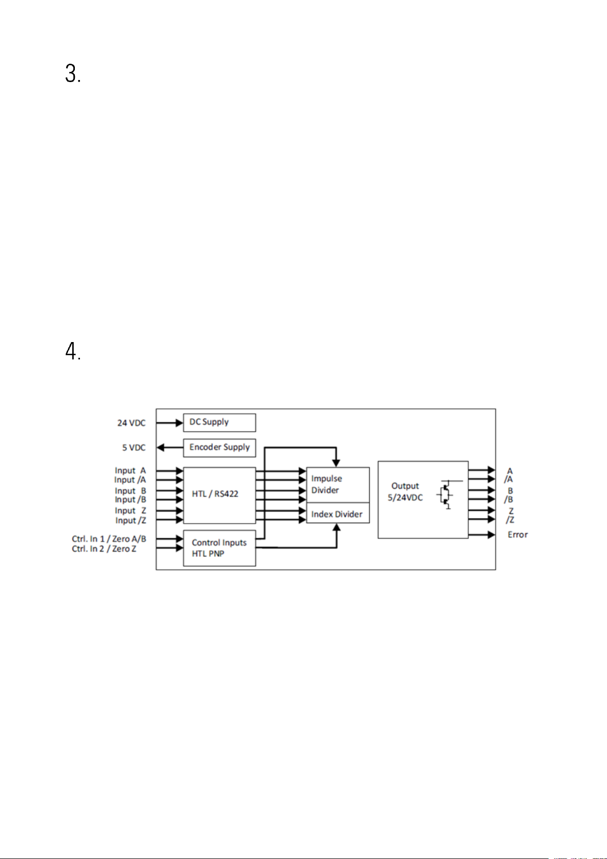
Introduction
The 7384.5010 is a universal interface using with incremental measuring systems.
The device allows the solution of the following problems:
• Level conversion (RS-422, HTL single ended, HTL differential, TTL and vice versa)
• Division of two-track A / B pulses with adjustable ratio 1: 1 to 1: 4096
• Division of the Z pulse with adjustable ratio 1: 1 to 1: 256
• External HTL signals for various functions
• Implementation between the two types of representations for the direction of rotation
(A/B 90 °, A/B Dir and vice versa, Division possible)
• Start / stop functionality via external ZERO_A signal
All settings are made on the DILL switches on the housing. The device consists of a compact
housing with screw terminals and can be mounted on a DIN rail.Block diagram
Block diagram
7384_5010_02b_oi_e.docx / Feb-21 Page 8 / 24

Electrical Connections
The terminal screws should be tightened with a slotted screwdriver (blade width 2mm).
DC Power Supply
The device is supplied with a DC voltage between 9 ... 30 VDC via terminals 1 and 2 of X1. The
current consumption depends on the level of the supply voltage and the settings and is approx.
35 mA without load from the sensor supply and additional on the extracted encoder current at
the auxiliary voltage output.
All GND terminals are internally interconnected.
Auxiliary Voltage Output
At terminal 8 and 9 of X4 the auxiliary voltage as encoder / sensor supply is +5.5 VDC and can
be charged with max. 250 mA.
7384_5010_02b_oi_e.docx / Feb-21 Page 9 / 24

Incremental Inputs A, /A, B, /B, Z, /Z
RS422
HTL DIFFERENTIAL
HTL PNP
At terminal 2 ... 7 of X4, 3 pulse inputs are available for HTL / TTL / RS422 signals. The unused
inputs must be open (HTL single ended vs. HTL differential) or terminated (unused Z track in RS422 or HTL differential format).
Wiring of the incremental inputs:
7384_5010_02b_oi_e.docx / Feb-21 Page 10 / 24

Control Inputs
Please note that all input and output signals refer to the same common
potential (GND) which at the same time is also the minus potential of the
power supply.
At any time, the total transmission characteristics of encoder, external
components and capacity of the cable must ensure proper signals at the
input terminals of the unit, with respect to the levels, the shape and the
phase displacement A/B.
Two control inputs with HTL PNP characteristics are available at terminals 2 and 3 of X2 and
are used for resetting the internal dividers
Unconnected control inputs are always “LOW”.
All inputs are designed to receive impulses from an electronic impulse source.
Notice for mechanical switching contacts:
When exceptionally mechanical contacts are used, please connect an external capacitor
between GND (-) and the corresponding input (+). A capacity of 10 µF will reduce the input
frequency to
20 Hz and miscounting due to contact bouncing will be eliminated.
Pulse output
Depending on the DIL switch setting, the pulses are available in HTL or RS-422 format at the
outputs of screw terminal X3 and are independent of the used format. The height of the pulse
level at the push-pull outputs in the HTL setting corresponds approximately to the input voltage
at the supply input X1.
7384_5010_02b_oi_e.docx / Feb-21 Page 11 / 24

Error Ausgang
An HTL error signal (input error, only with RS-422 or HTL differential) is available at the X3
screw terminal 1. (Error = low).
The error is triggered by a line fault (short circuit or line break) by the input lines A, / A, B, / B or
Z, / Z. (Test mode OFF, DIL2 / 2 = OFF.
The DIL switch DIL3 (right, 3-pin) can be used to select the corresponding channel. If the DIL3 /
1 contact is set to OFF, no errors are evaluated on the A, / A line, DIL3 / 2 refers to the line B, /
B and DIL3 / 3 to the line Z, / Z.
An error can only be detected in RS-422 or HTL differential format, all other formats will not
trigger an error.
LED
The green LED indicates operational readiness (power supply switched on).
The yellow LED signals an input error. (only with RS-422 or HTL differential)
7384_5010_02b_oi_e.docx / Feb-21 Page 12 / 24

Input and output configuration
Changes in the settings on the DIL switches will only be taken over by the
device after the supply voltage has been switched on again!
Configuration
DIL1 (Front 8-pole)
Function
1 2 3 4 5 6 7
8
ON
Level for HTL Single Ended: UL < 10V / UH > 14V
OFF
Level for HTL Single Ended: U < 5V / U > 9V
ON
ON Input format: TTL
ON
OFF
Input format: HTL Single Ended
OFF
ON Input format: RS-422
OFF
OFF
Input format: HTL Differential
ON
ON Z-pulse length: 1 Z-Puls, independent of A / B
OFF
ON Z-pulse length: ynchronized with AOUT / BOUT
ON
OFF
Z-pulse length: synchronized with AIN / BIN
OFF
OFF
Z-pulse length: 1 Z-Puls, a depending on A/B
ON
Input Mode : A/B Dir (Pulse / Direction)
OFF
Input Mode : A/B 90°
ON Output Mode : A/B Dir (Pulse / Direction)
OFF
Output Mode : A/B 90°
ON
Highest divider for A / B divider on (2048)
OFF
Highest divider for A / B divider off (2048) Configuration
DIL2 (Front 3-pole)
Function
1 2 3
ON
Z-pulse: Generation of a Z-pulse from AIN & BIN, AOUT & BOUT
OFF
Z-pulse: Z input is used
OFF
Test mode deactivated: OFF
ON
Output format : HTL Differential, HTL Single Ended (
UX1(2)
– 2V)
OFF
Output format: RS-422, TTL (5V)
7384_5010_02b_oi_e.docx / Feb-21 Page 13 / 24

Level converter A/B Pulse (A/B Divider: All OFF)
Divider [A/B]
DIL5
(Left 8-pole)
DIL6
(Left 3-pole)
DIL1
(Front)
Comment
1 2 3 4 5 6 7 8 1 2 3 8
Binary value
1 2 4
8
16
32
64
128 256 512
1024
2048
OFF
OFF
OFF
OFF
OFF
OFF
OFF
OFF
OFF
OFF
OFF
OFF
AIN = AOUT, BIN = BOUT
If the A/B pulse have to be switched unchanged from the input to the output (no division, no
change in length and position), then the DIL switch position listed below must be chosen. A
level conversion is only possible if the input mode (A/B 90 ° or A/B dir) corresponds to the
output mode. (DIL1/6 = DIL1/7).
Input/Output Mode Converter (A/B Divider: All OFF)
If input mode differs from output mode and in addition, the DIL switches DIL5 and DIL6 of the
divider A/B are all set to OFF, the following signal characteristics are set up at the output.
Case 1: Input A/B 90°, Output A/B Dir
DIL1/6 = OFF, DIL1/7 = ON with A/B Divider setting: DIL5, 6 = all OFF
If the direction of the A/B 90 ° signal changes at the input, a change takes place at the BOUT
output signal. (A/B dir). There is no division.
Case 2: Input A/B Dir, Output A/B 90°
DIL1/6 = ON, DIL1/7 = OFF with A/B Divider setting: DIL5, 6 = all OFF
If a change takes place at the BIN input signal (A/B dir), the direction of the A/B 90 ° signal
changes at the output. Here is a division 1:2, from the input in relation to the output.
7384_5010_02b_oi_e.docx / Feb-21 Page 14 / 24

Adjustable divider A/B
Divider [A/B]
DIL5
(Left 8-pole)
DIL6
(Left 3-pole)
DIL1
(Front)
Comment
1 2 3 4 5 6 7 8 1 2 3 8
Binary value
division =>
1 : (Binary value +1) x2
1 2 4
8
16
32
64
128 256 512
1024
2048
ON
OFF
OFF
OFF
OFF
OFF
OFF
OFF
OFF
OFF
OFF
OFF
value 1 => 1 : 4
OFF
ON
OFF
OFF
OFF
OFF
OFF
OFF
OFF
OFF
OFF
OFF
value 2 => 1 : 6
ON
ON
OFF
OFF
OFF
OFF
OFF
OFF
OFF
OFF
OFF
OFF
value 3 => 1 : 8
OFF
OFF
ON
OFF
OFF
OFF
OFF
OFF
OFF
OFF
OFF
OFF
value 4 => 1 : 10
ON
OFF
ON
OFF
OFF
OFF
OFF
OFF
OFF
OFF
OFF
OFF
value 5 => 1 : 12
OFF
...etc.
OFF
OFF
OFF
OFF
OFF
OFF
OFF
OFF
OFF
ON
OFF
OFF
1 : 1026
OFF
OFF
OFF
OFF
OFF
OFF
OFF
OFF
OFF
OFF
ON
OFF
1 : 2050
ON
ON
ON
ON
ON
ON
ON
ON
ON
ON
ON
OFF
1 : 4096
ON
ON
ON
ON
ON
ON
ON
ON
ON
ON
ON
ON
1 : 8192
Setting the A/B Divider (at A/B Dir to A/B 90°)
The division ratio for the A/B pulses is set at the DIL switches DIL5 and DIL6. The switch
positions use a binary code like shown in the subsequent list. (DIL1/6 = ON, DIL1/7 = OFF).
Example: Input A/B dir, output A/B 90 ° with A/B division 1:6 (setting DIL6, 5: OFF ON OFF)
Division 1:2: See Input/Output Mode Conversion (A/B Divider: All OFF)
7384_5010_02b_oi_e.docx / Feb-21 Page 15 / 24

Setting the A/B divider (for all other modes)
Divider [A/B]
DIL5
(Left 8-pole)
DIL6
(Left 3-pole)
DIL1
(Front)
Comment
1 2 3 4 5 6 7 8 1 2 3
8
Binary value
division =>
1 : Binary value +1
1 2 4
8
16
32
64
128 256 512
1024
2048
ON
OFF
OFF
OFF
OFF
OFF
OFF
OFF
OFF
OFF
OFF
OFF
value 1 => 1 : 2
OFF
ON
OFF
OFF
OFF
OFF
OFF
OFF
OFF
OFF
OFF
OFF
value 2 => 1 : 3
ON
ON
OFF
OFF
OFF
OFF
OFF
OFF
OFF
OFF
OFF
OFF
value 3 => 1 : 4
OFF
OFF
ON
OFF
OFF
OFF
OFF
OFF
OFF
OFF
OFF
OFF
value 4 => 1 : 5
ON
OFF
ON
OFF
OFF
OFF
OFF
OFF
OFF
OFF
OFF
OFF
value 5 => 1 : 6
OFF
ON
ON
OFF
OFF
OFF
OFF
OFF
OFF
OFF
OFF
OFF
value 6 => 1 : 7
ON
ON
ON
OFF
OFF
OFF
OFF
OFF
OFF
OFF
OFF
OFF
value 7 => 1 : 8
OFF
...etc.
OFF
OFF
OFF
OFF
OFF
OFF
OFF
OFF
OFF
ON
OFF
OFF
1 : 513
OFF
OFF
OFF
OFF
OFF
OFF
OFF
OFF
OFF
OFF
ON
OFF
1 : 1025
ON
ON
ON
ON
ON
ON
ON
ON
ON
ON
ON
OFF
1 : 2048
ON
ON
ON
ON
ON
ON
ON
ON
ON
ON
ON
ON
1 : 4096
The division ratio for the A/B pulses is set at the DIL switches DIL5 and DIL6. The switch
positions use a binary code like shown in the subsequent list. (DIL1/6 = OFF, DIL1/7 = X).
Example: Input A/B 90°, output A/B 90 ° with A/B division 1:6 (setting DIL6, 5: OFF ON OFF
7384_5010_02b_oi_e.docx / Feb-21 Page 16 / 24

Example: Input A/B 90°, output A/B 90 ° with A/B division 1:3 (setting DIL6, 5: OFF ON OFF
Example: Input A/B 90°, output A/B 90 ° with A/B division 1:3 (setting DIL6, 5: OFF ON OFF
7384_5010_02b_oi_e.docx / Feb-21 Page 17 / 24

Setting to zero the A/B divider with ZERO_A Signal
The divider will only be reset in the zero phase of the output signals AOUT and BOUT and will
remain as long as the signal is attached. This prevents the miscounting of subsequent circuits.
This function can only be applied to A/B 90°, it is independent of the divider ratio.
If there is a high signal at ZERO_A the A/B divider is reset and has the starting state AOUT =
BOUT = Low. The divider is in a defined state. Depending on the direction of the input signals,
the next split A/B pulse appears immediately after the reset, or after the set division ratio. The
length of the ZERO_A pulse has to be greater than the period of frequency, than it can be
switched off. This feature can be used for define start and stop.
The Z track can be set to zero with the ZERO_A input. The DIL switch DIL1/8 has been set to
ON, A/B 90 ° output signals have been selected and the Z Pulse length has been synchronized
to the output.
Informationen over the signal change A/B Dir
Signal changes from B (direction) should appear shortly before or latest at the same time as the
A flank so that the change can be detected correctly.
7384_5010_02b_oi_e.docx / Feb-21 Page 18 / 24

Adjustable divider Z
Divider [Z]
DIL4 (right 8-pole)
Comment
Binary value
1 2 3 4 5 6 7
8
1 2 4
8
16
32
64
128
OFF
OFF
OFF
OFF
OFF
OFF
OFF
OFF
ZIN = ZOUT (ZERO_Z = Low)
Divider [Z]
DIL4 (right 8-pole)
Comment
Binary value
Divider => 1: Binary value +1
1 2 3 4 5 6 7
8
1 2 4
8
16
32
64
128
ON
OFF
OFF
OFF
OFF
OFF
OFF
OFF
1 : 2
OFF
ON
OFF
OFF
OFF
OFF
OFF
OFF
1 : 3
ON
ON
OFF
OFF
OFF
OFF
OFF
OFF
1 : 4
OFF
OFF
ON
ON
ON
ON
ON
ON
1 : 253
ON
OFF
ON
ON
ON
ON
ON
ON
1 : 254
OFF
ON
ON
ON
ON
ON
ON
ON
1 : 255
ON
ON
ON
ON
ON
ON
ON
ON
1 : 256
Pegel conversion Z Puls (Z Divider: all OFF)
If the Z pulse have to be switched unchanged from the input to the output (no division, no
change in length and position), then the DIL switch position listed below must be chosen.
The output at the level conversion can be set to zero (ZOUT = Low) with the control input X2(3)
ZERO_Z = High.
The function is active as long as there is a high level at the control input. The Z pulse can be
trimmed by switching.
Setting the Z Divider
The programming of the Z divider is subject to the same rules as the programming of the A/B
divider.
7384_5010_02b_oi_e.docx / Feb-21 Page 19 / 24

Location and width of the Z pulse
DIL1 Front
8-pole
Wide Z pulse (a full encoder turn)
4
5
ON
ON
The pulse width at the output corresponds to the full distance between two Z
pulses at the input.
DIL1 Front
8-pole
Narrow Z pulse (1/4 output-periode)
(Only applicable to input signals A/B 90°, DIL1/6 = OFF)
4 5
ON
OFF
The pulse width at the output corresponds to ¼ period of pulse width at the input.
If the DIL switch DIL4 of the Z divider is completely set to OFF, the Z Pulse is forwarded from
the input directly to the output (see level conversion Z Puls).
All pictures in this section assume that the A/B divider is set to 8. The Z Pulse is divided
according to its divider (additionally DIL2/1 on OFF, ZIN is used, Z dividers not complete on
OFF).
Depending on the length or location of the Z Pulses input and through the synchronization to
the input or output signals, the Z pulse at the output can fluctuate around an input or output
period (not with DIL1/5 = DIL1/4 = ON).
7384_5010_02b_oi_e.docx / Feb-21 Page 20 / 24

DIL1 Front
8-pole
Narrow Z pulse (1/4 output-periode)
(Only applicable to output signals A/B 90°, DIL1/7 = OFF)
4 5
ON
OFF
The pulse width at the output corresponds to ¼ period of pulse width at the
output.
DIL1 Front
8-pole
Wide Z pulse (a full encoder turn)
4 5
ON
ON
The pulse width at the output corresponds to the full distance between two
Z pulses at the input.
In this operation mode, only division ratios may be used, which together with the A/B divisor
deliver clear and completely results. A division with rest causes that the Z pulse at the output
can fluctuate around an input or output period.
Example:
If at an encoder with 1000 pulses the A/B devider were set to 3 and at the same time the Z
Pulse divider were set to 2, then the Z Pulse at the output would have to appear after 666,666
pulses, which is not physically possible.
Independent Z Divider
The Z divider works independently of the A/B track, the directional evaluation of the A/B signal
does not affect the counting sequence (additionally DIL2/1 on OFF, ZIN is used, Z divider not
completely set to OFF).
7384_5010_02b_oi_e.docx / Feb-21 Page 21 / 24

Automatic generation of a Z pulse
DIL1 Front
8-pole
Narrow Z puls e (1/4 output- or input-period)
4
5
OFF
ON
The Z pulse is generated from the input signal A/B. Each input period
generates one count for the Z divider.
The Z pulse width at the output corresponds to 1/4 period of the pulse width of
the input signal A/B (Only applicable to input signals A/B 90°, DIL1/6 = OFF).
ON
OFF
The Z pulse is generated from the output signal A/B. Each output period
generates one count for the Z divider.
The Z pulse width at the output corresponds to 1/4 period of the pulse width of
the output signal A/B (Only applicable to output signals A/B 90°, DIL1/7 = OFF).
If the DIL switch DIL2/1 is set to ON, a Z pulse can be automatically generated.
The Z input is ineffective and does not need to be connected (Z divider not completely set on
OFF).
Reset the Z divider with ZERO_Z Signal
The Z divider can be reset by applying a high signal to the control input ZERO_Z.
The reset will act immediately and as long as the signal is applied.
Depending on the direction of the A/B track, the next Z pulse appears immediately after the
reset or according to the set division ratio (not at the independent Z divider).
The reset of the Z divider can also be performed in case of automatic generation of the Z pulse.
By setting the Z-divider = all OFF, the setting of the ZERO_Z input causes an immediate zero
setting of the output ZOUT (see level conversion Z pulse).
Note the special case in which the ZERO_A signal can also set the Z output to zero (see Setting
to zero of the A/B divider with ZERO_A signal)
7384_5010_02b_oi_e.docx / Feb-21 Page 22 / 24

Dimensions
7384_5010_02b_oi_e.docx / Feb-21 Page 23 / 24

Technical Specifications
Technical Specifications
Connections
Connection type:
Screw terminals, 1,5 mm² / AWG 16
Power supply:
Input voltage:
Protection circuit:
Ripple:
Consumption:
9 … 30 VDC
reverse polarity protection
≤ 10 %
approx. 40 mA (at 9 V, unloaded)
approx. 30 mA (at 30 V, unloaded)
Sensor supply:
Output voltage:
Output current:
+ 5,5 VDC +/- 5 %
max. 250 mA
Incremental inputs:
Number:
Traces:
Configuration:
RS422:
HTL Differential:
HTL Signal Ended:
TTL:
3
A, B, Z (HTL Single Ended, TTL)
A, /A, B, /B, Z, /Z (RS422, HTL Differential )
RS422, HTL Differential, HTL Single Ended, TTL
max. 1 MHz (RS422 Differential signal > 1 V)
max. 1 MHz (HTL Differential signal > 2 V)
max. 350kHz, level 1: Low 0 … 10V, High 14 … 30 V
level 2: Low 0 … 5V, High 9 … 30 V
max. 350kHz, Low 0 … 0.7V, High 2.2 … 5 V
Control inputs:
Number:
Format:
Frequency:
Response time:
Load:
2
HTL, PNP (Low 0 … 5 V, High 9 … 30 V)
max. 20kHz
50 µs
max. 3mA
Incremental outputs:
Number:
Traces:
Format / level:
Output current:
Response time:
3
A, /A, B, /B, Z, /Z
HTL: 8 … 29 V (depending on the supply voltage)
RS422: 5 V
max. 20 mA / Push-Pull
approx. 600ns
Housing:
Material:
Mounting:
Dimensions (w x h x d):
Protection class:
Weight:
plastic
35 mm top hat rail (according to EN 60715)
22,5 x 102 x 102 mm / 0,886 x 4,016 x 4,016”
IP20
approx. 100 g
Ambient temperature:
Operation:
Storage:
0 °C … +60 °C / +32 … +140 °F (not condensing)
-25 °C … +70 °C / -13 … +158 °F (not condensing)
Failure rate:
MTBF in years:
109,3 (long-term usage at 60 °C / 140 °F )
Conformity & standards:
EMC 2014/30/EU:
RoHS (Ⅱ) 2011/65/EU
RoHS (Ⅲ) 2015/863:
EN 61326-1: 2013 for industrial location
EN 55011: 2017 / CISPR11: 2017 Class A
EN IEC 63000: 2018
7384_5010_02b_oi_e.docx / Feb-21 Page 24 / 24
 Loading...