

Motrona 7085.5010, 7386.5010, 8086.5010, 9085.5010 User guide

Operating Manual
Signal converter 7085.5010 / 7386.5010 / 8086.5010 / 9085.5010
Frequency (7085.5010)
Analog (current / voltage)
Serial (RS232 / RS485)
SSI absolute value (7386.5010)
Start-Stop (8086.5010)
Pulse counter (9085.5010)
Product features:
Multifunctional unit with several operating modes for incremental encoders or SSI absolute encoders
For incremental encoders:
Operating modes as frequency converter or position transducer (pulse counter)
Universal incremental inputs (HTL/TTL/RS422) for NPN/PNP/NAMUR encoders and sensors
Functions such as linkages (eg. A+B), scaling, filters, start-up bridging, …
Input frequencies up to 1 MHz
For SSI absolute encoders:
Master or Slave operation with clock frequencies up to 1 MHz
For single turn and multi turn encoders with SSI formats from 10 … 32 Bit
Functions such as bit suppression, round-loop function, scaling, …
For absolute and magnetostrictive position encoder with Start-Stop-Interface:
Operating modes for master or slave, for position, angle and speed measurement
16 bit analog output, configurable for voltage or current operation
USB interface and RS232/RS485-interface for configuration and serial readout
Extremely short conversion times
Linearization with 24 control points
Auxiliary voltage output 5 and 24VDC for encoder supply
Numerous connection options via 6 control inputs and 6 control outputs
Compact rail housing to EN60715
Easy parameterization via user interface OS (Freeware)
motrona GmbH, Zeppelinstraße 16, DE - 78244 Gottmadingen, Tel. +49 (0) 7731 9332-0, Fax +49 (0) 7731 9332-30, info@motrona.com, www.motrona.com

Version:
Description:
9085.5010_01a_oi/tgo/April 19
First Version
9085.5010_01b/mbo/August 19
New added: chapter “Compatibility Hint”
9085.5010_02a_oi/tgo/November 19
Extension of QR-code and of new filter functions at Mode
Frequency
9085.5010_02b_oi/mbo/December 19
Revised Version
9085.5010_03a_oi/mbo/tgo/Januar 20
Extension by start-stop-interface
9085.5010_03b_oi/mbo/April 2020
New connection diagram in chapter 4, failure rate added
9085.5010_04a_oi/mbo/August 2020
New USB interface at X7
Legal notices::
All contents included in this manual are protected by the terms of use and copyrights of motrona
GmbH. Any reproduction, modification, usage or publication in other electronic and printed media
as well as in the internet requires prior written authorization by motrona GmbH.
9085_5010_04a_oi_e.docx / Feb-21 page 2 / 72

Table of Contents
Safety Instructions and Responsibility .......................................................................... 5
General Safety Instructions ............................................................................................................. 5
Use according to the intended purpose .......................................................................................... 5
Installation ....................................................................................................................................... 6
EMC Guidelines ............................................................................................................................... 7
Cleaning, Maintenance and Service Notes..................................................................................... 7
Compatibility Hint ........................................................................................................ 8
Introduction .................................................................................................................. 9
Operating Mode ............................................................................................................................... 9
Function diagram ............................................................................................................................. 9
Power – LED / Error messages ...................................................................................................... 10
Electrical Connections ................................................................................................ 11
DC Power Supply (X1) .................................................................................................................... 11
Auxiliary voltage output (X2) ......................................................................................................... 11
Incremental encoder input (X2) ..................................................................................................... 12
SSI-Absolute encoder input (X2) ................................................................................................... 14
Start-stop encoder inputs (X2) ....................................................................................................... 16
Control Inputs (X5) ......................................................................................................................... 17
Analog output (X4) ......................................................................................................................... 18
Serial interface (X3) ....................................................................................................................... 19
USB interface (X7) .......................................................................................................................... 19
Control outputs (X6) ....................................................................................................................... 20
Parameter / Overview-Menu Structure ....................................................................... 21
General Menu ................................................................................................................................ 24
Mode Frequency ............................................................................................................................ 26
Mode Counter ................................................................................................................................ 31
Mode SSI........................................................................................................................................ 32
Mode Start/Stop ............................................................................................................................ 34
Preselection Values ....................................................................................................................... 36
Preselection 1 Menu ...................................................................................................................... 37
Preselection 2 Menu ...................................................................................................................... 40
Preselection 3 Menu ...................................................................................................................... 41
Preselection 4 Menu ...................................................................................................................... 42
Preselection 5 Menu ...................................................................................................................... 43
Preselection 6 Menu ...................................................................................................................... 44
Serial Menu ................................................................................................................................... 45
Analog Menu ................................................................................................................................. 48
Command Menu ............................................................................................................................. 49
Linearization Menu ........................................................................................................................ 51
Appendix .................................................................................................................... 52
Data readout via serial interface ................................................................................................... 52
Modbus RTU Interface ................................................................................................................... 53
Parameter setting .............................................................................................................................. 53
Read Holding Registers and Write Multiple Registers .................................................................... 54
Read Coils and Write Single Coil ...................................................................................................... 55
9085_5010_04a_oi_e.docx / Feb-21 page 3 / 72

Diagnose ............................................................................................................................................ 56
Parameter / serial codes................................................................................................................ 57
Linearization ................................................................................................................................... 63
Reading SSI-Value ......................................................................................................................... 65
Internal processing and calculation of SSI data ........................................................................... 66
Operating modes / OP modes of the Start/Stop interface ........................................................... 69
Dimensions .................................................................................................................................... 71
Technical Specifications: ............................................................................................................... 72
9085_5010_04a_oi_e.docx / Feb-21 page 4 / 72

Safety Instructions and Responsibility
General Safety Instructions
This operation manual is a significant component of the unit and includes important rules and hints
about the installation, function and usage. Non-observance can result in damage and/or impairment
of the functions to the unit or the machine or even in injury to persons using the equipment!
Please read the following instructions carefully before operating the device and observe all safety
and warning instructions! Keep the manual for later use.
A pertinent qualification of the respective staff is a fundamental requirement in order to use these
manual. The unit must be installed, connected and put into operation by a qualified electrician.
Liability exclusion: The manufacturer is not liable for personal injury and/or damage to property and
for consequential damage, due to incorrect handling, installation and operation. Further claims, due
to errors in the operation manual as well as misinterpretations are excluded from liability.
In addition the manufacturer reserves the right to modify the hardware, software or operation
manual at any time and without prior notice. Therefore, there might be minor differences between
the unit and the descriptions in operation manual.
The raiser respectively positioner is exclusively responsible for the safety of the system and
equipment where the unit will be integrated.
During installation or maintenance all general and also all country- and application-specific safety
rules and standards must be observed.
If the device is used in processes, where a failure or faulty operation could damage the system or
injure persons, appropriate precautions to avoid such consequences must be taken.
Use according to the intended purpose
The unit is intended exclusively for use in industrial machines, constructions and systems. Nonconforming usage does not correspond to the provisions and lies within the sole responsibility of the
user. The manufacturer is not liable for damages which have arisen through unsuitable and improper
use.
Please note that device may only be installed in proper form and used in a technically perfect
condition (in accordance to the Technical Specifications). The device is not suitable for operation in
explosion-proof areas or areas which are excluded by the EN 61010-1 standard.
9085_5010_04a_oi_e.docx / Feb-21 page 5 / 72

Installation
The device is only allowed to be installed and operated within the permissible temperature range.
Please ensure an adequate ventilation and avoid all direct contact between the device and hot or
aggressive gases and liquids.
Before installation or maintenance, the unit must be disconnected from all voltage-sources. Further
it must be ensured that no danger can arise by touching the disconnected voltage-sources.
Devices which are supplied by AC-voltages must be connected exclusively by switches, respectively
circuit-breakers with the low voltage network. The switch or circuit-breaker must be placed as near
as possible to the device and further indicated as separator.
Incoming as well as outgoing wires and wires for extra low voltages (ELV) must be separated from
dangerous electrical cables (SELV circuits) by using a double resp. increased isolation.
All selected wires and isolations must be conform to the provided voltage- and temperature-ranges.
Further all country- and application-specific standards, which are relevant for structure, form and
quality of the wires, must be ensured. Indications about the permissible wire cross-sections for
wiring are described in the Technical Specifications.
Before first start-up it must be ensured that all connections and wires are firmly seated and secured
in the screw terminals. All (inclusively unused) terminals must be fastened by turning the relevant
screws clockwise up to the stop.
Overvoltages at the connections must be limited to values in accordance to the overvoltage
category II.
9085_5010_04a_oi_e.docx / Feb-21 page 6 / 72

EMC Guidelines
All motrona devices are designed to provide high protection against electromagnetic interference.
Nevertheless you must minimize the influence of electromagnetic noise to the device and all connected
cables.
Therefore the following measures are mandatory for a successful installation and operation:
Use shielded cables for all signal and control input and output lines.
Cables for digital controls (digital I/O, relay outputs) must not exceed a length of 30 m and are
allowed for in building operation only
Use shield connection clamps to connect the cable shields properly to earth
The wiring of the common ground lines must be star-shaped and common ground must be
connected to earth at only one single point
The device should be mounted in a metal enclosure with sufficient distance to sources of
electromagnetic noise.
Run signal and control cables apart from power lines and other cables emitting electromagnetic
noise.
Please also refer to motrona manual “General Rules for Cabling, Grounding, Cabinet Assembly”. You can
download that manual by the link
https://www.motrona.com/en/support/general-certificates.html
Cleaning, Maintenance and Service Notes
To clean the front of the unit please use only a slightly damp (not wet!), soft cloth. For the rear no
cleaning is necessary. For an unscheduled, individual cleaning of the rear the maintenance staff or
assembler is self-responsible.
During normal operation no maintenance is necessary. In case of unexpected problems, failures or
malfunctions the device must be shipped for back to the manufacturer for checking, adjustment and
reparation (if necessary). Unauthorized opening and repairing can have negative effects or failures to
the protection-measures of the unit.
9085_5010_04a_oi_e.docx / Feb-21 page 7 / 72
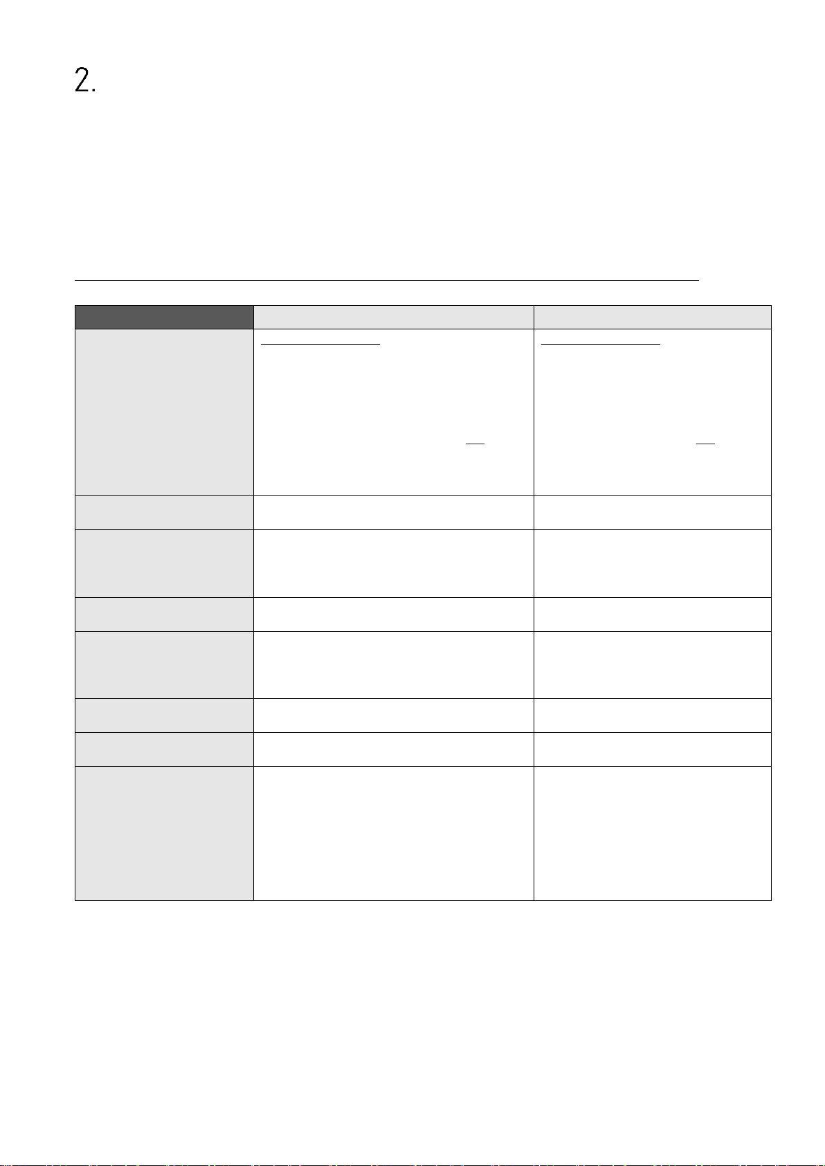
Compatibility Hint
9085.5010 / 7085.5010 / 7386.5010
9085.5052 / 7085.5052 / 7386.5051
Incremental Input:
(9085/7085)
Possible configurations:
RS422 (TTL), HTL Differential, HTL PNP, HTL
NPN or TTL PNP (asymmetrical)
The setting made in the corresponding
parameter then applies to both inputs (A and
B).
Possible configurations:
RS422 (TTL), HTL Differential, HTL
PNP, HTL NPN or TTL (asymmetrical)
The desired setting can be made
separately for each channel (A and B)
using the corresponding DIL
switches.
Control Inputs:
Number of inputs: 6
Format: HTL
Number of inputs 1
Format: HTL
Control Outputs:
Number of outputs: 6
Format / Level: 5…30 V, PNP
Output current: max. 200 mA
Reaction time: < 1ms
No switching outputs
Encoder Supply:
Output voltage: 5VDC u. 24VDC
Output current: max. 250 mA
Output voltage: 5VDC
Output current: max. 250 mA
Serial Interface:
RS232/RS485 via screw terminals
Baud rate: 9600, 19200 or 38400 Baud
RS232/RS485 via 9-position SUB-D
connector (female)
Baud rate: 600, 1200, 2400, 4800,
9600, 19200, or 38400 Baud
Housing:
Dimensions (w x h x d): 23 x 102 x 102 mm
Weight: approx. 100 g
Dimensions (w x h x d): 40 x 79 x 91 mm
Weight: approx. 190 g
Device parameterization:
Only by operator software OS.
By operator software OS and
partially via DIL switches
Operating modes for FU:
Only channel A
Ratio B/A
Percentage deviation from channel B to A
Sum A+B
Difference A-B
A/Bx90
Only channel A
Ratio A/B
Sum A+B
A/Bx90
Only channel B
Product AxB
Difference A-B
A= Impulse, B = Direction
This product is a successor model of the thousand fold proven converter type
9085.5052 / 7085.5052 / 7386.5051.
This converter is able to replace functionally the previous model; however some minor differences
have to be observed with regard to the parameter settings.
The main differences between this product and the respective predecessor model are listed below.
Differences of the 9085.5010 / 7085.5010 / 7386.5010 compared to the previous models are:
9085_5010_04a_oi_e.docx / Feb-21 page 8 / 72
Introduction
The device is designed as a signal converter with control inputs and outputs. Its extensive functions
make it universally applicable.
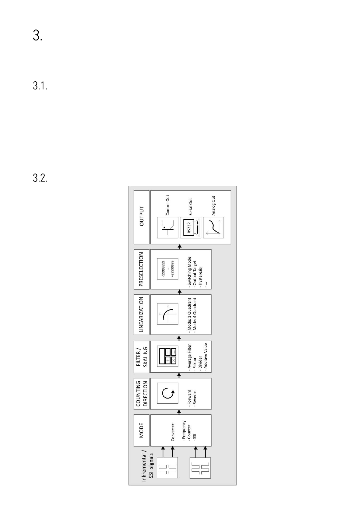
Operating Mode
Basically all functions have to be configured in the parameter menu. The device can be used in the
following operating modes:
Operation as frequency converter for incremental input signals (replaces 7085.5052)
Operation as position transducer / counter for incremental input signals (replaces 9085.5052)
Operation as absolute value converter for signals of a start-stop interface
Operation as absolute value converter for SSI signals (replaces 7386.5051)
Function diagram
9085_5010_04a_oi_e.docx / Feb-21 page 9 / 72

Power – LED / Error messages
Errorcode:
(Error_Status)
Error identification:
Error description:
0x00000001
Maximum Value
Measured value is greater than 99999999
0x00000002
Minimum Value
Measured value is less than -99999999
0x00000004
SSI Encoder Error
SSI error bit set (only for 7386.5010)
0x00000008
Encoder Fault
For internal test purposes only!
0x00000010
Frequency (Input A) out of range
Maximum or minimum permissible input
frequency at input A has been exceeded
or fallen below with the exponential filter
setting used.
0x00000020
Frequency (Input B) out of range
Maximum or minimum permissible input
frequency at input B has been exceeded
or fallen below with the exponential filter
setting used.
0x00000040
Start/Stop Encoder Error
No "start" and no "stop" pulse detected
between two "init" pulses. (only for
8086.5010)
Check sensor connections!
0x00000080
Position Encoder Outside the
Limit
No "start" and no "stop" pulse detected
between two "init" pulses. (only for
8086.5010)
Possible cause: No position sensor or
position sensor outside the limits.
The device has a green LED on its front foil. This lights up permanently as soon as the supply voltage
of the device has been applied. If an error occurs, the LED flashes at 1 Hz.
The analog output is also controlled with 0 V or 0/4 mA. If the error no longer exists, the LED
automatically lights up again permanently and the analogue output responds to the current result.
The exact error can be read out via the serial interface via the user interface (OS).
( Variable: Error_Status, Code: "; 3")
The individual error codes are explained below:
9085_5010_04a_oi_e.docx / Feb-21 page 10 / 72
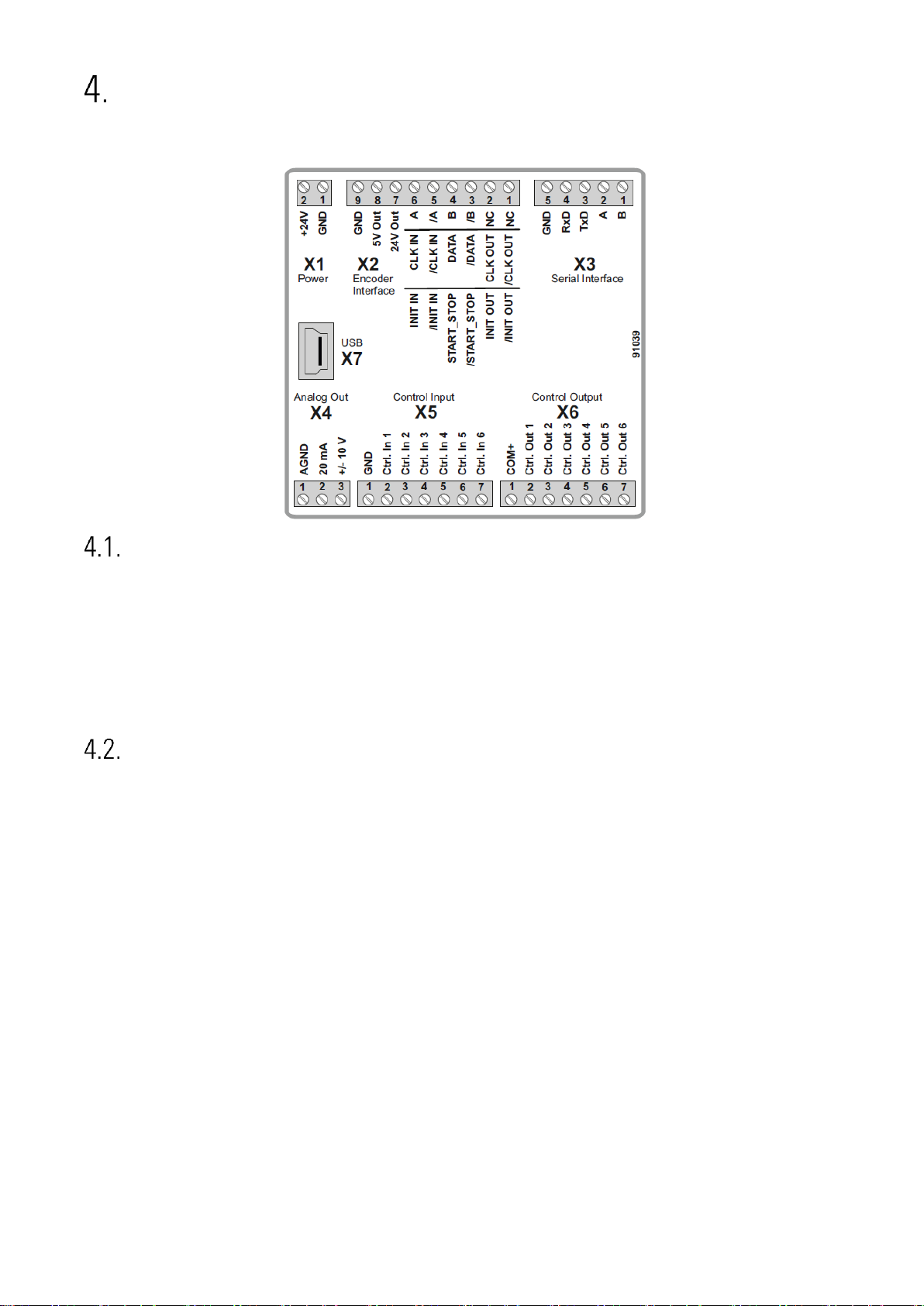
Electrical Connections
The terminal screws should be tightened with a slotted screwdriver (blade width 2mm).
DC Power Supply (X1)
The unit accepts DC supply from 18 to 30 V at the terminals X1 1 and 2. The power consumption
depends on the level of the supply voltage with aprox. 50 mA and the additional current required at
the Auxiliary Voltage Output.
All GND terminals are internally interconnected.
Auxiliary voltage output (X2)
Two auxiliary voltages (24 VDC and 5 VDC) are available as encoder / sensor supply at terminal X2
pins 7, 8 and 9. The 24 VDC output voltage depends on the device supply (see technical data).
9085_5010_04a_oi_e.docx / Feb-21 page 11 / 72
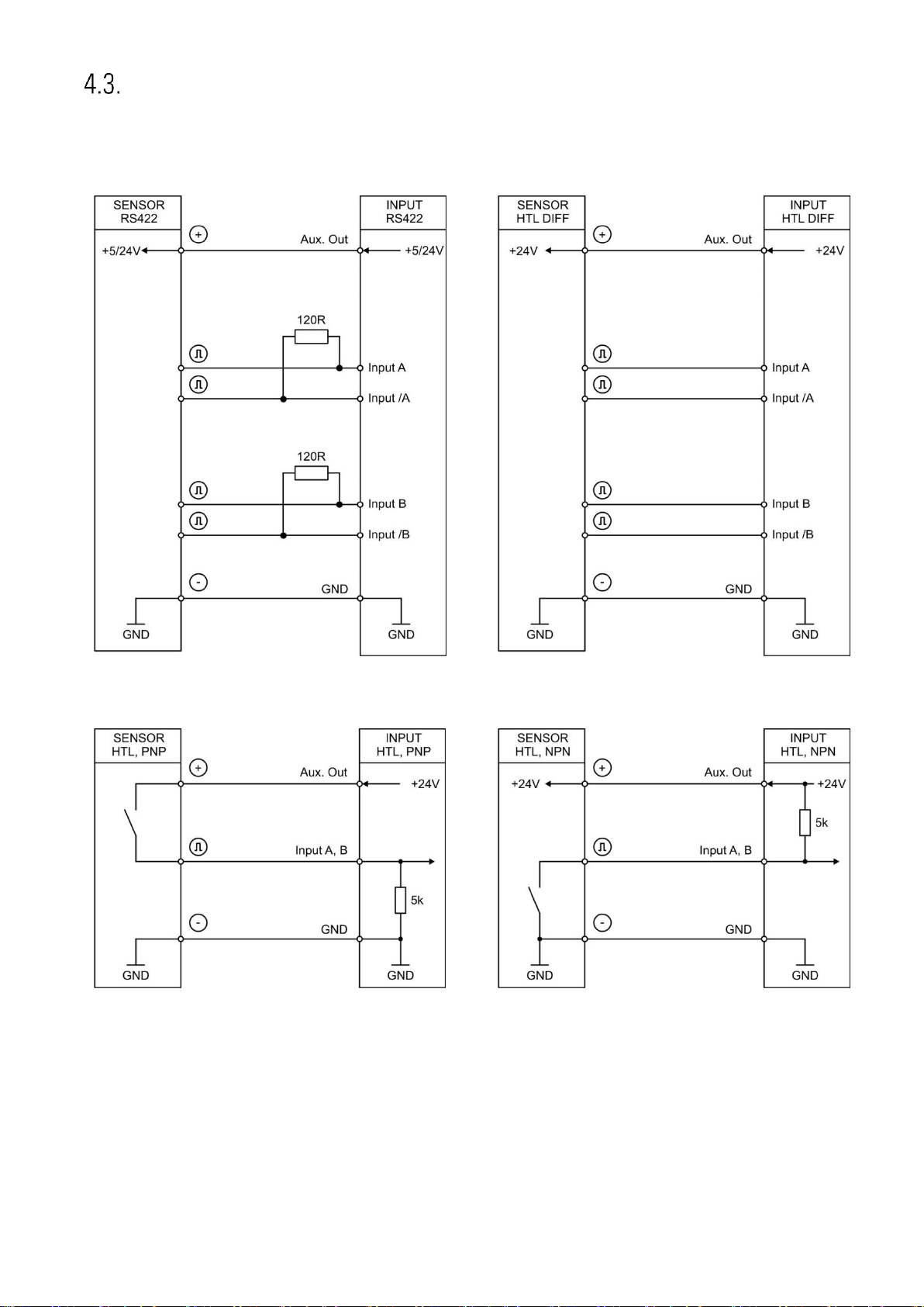
Incremental encoder input (X2)
RS422
HTL DIFFERENTIAL
HTL PNP
HTL NPN
Terminal X2 pins 3, 4, 5 and 6 provide a connection for various incremental signals.
9085_5010_04a_oi_e.docx / Feb-21 page 12 / 72
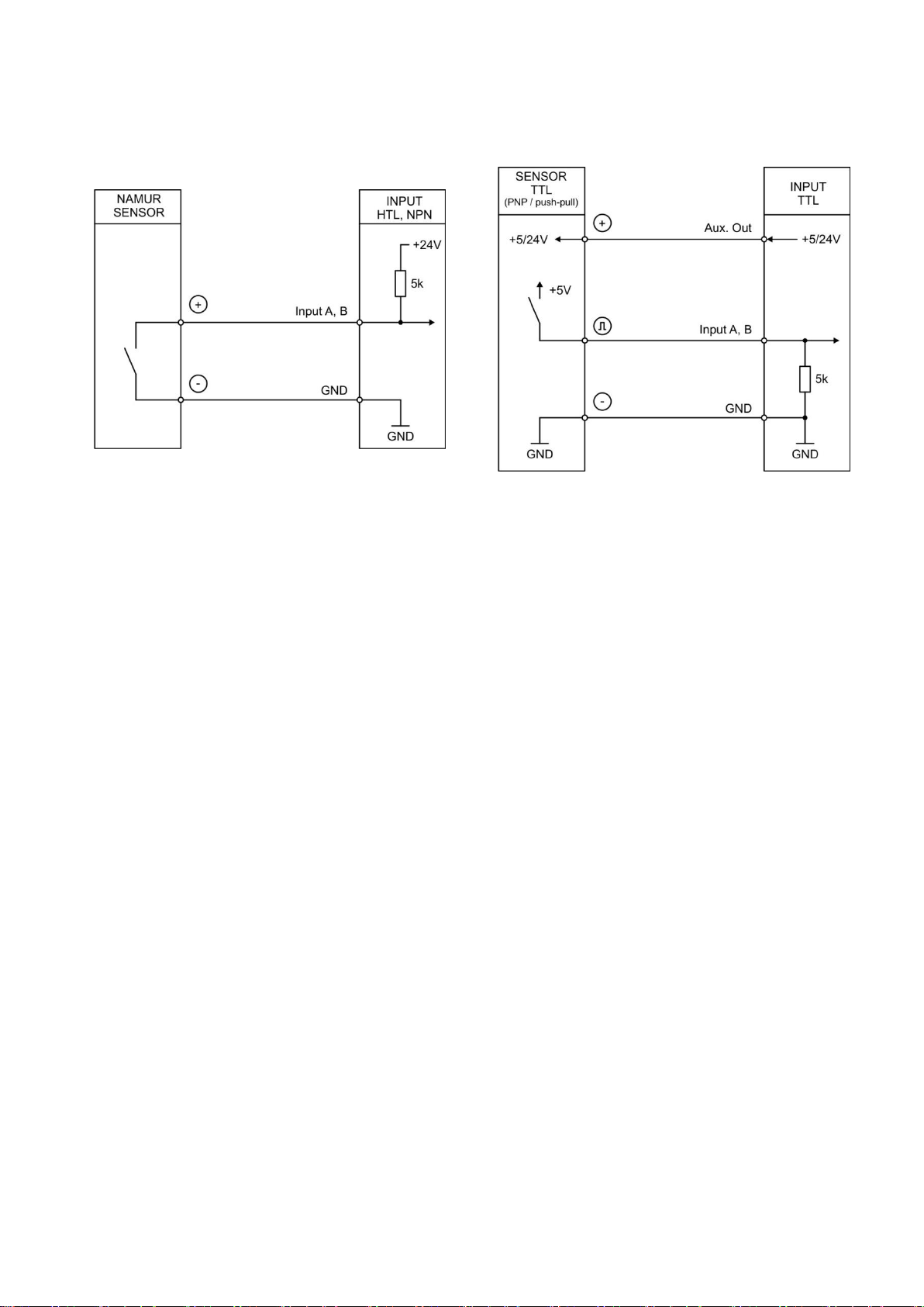
Continuation „Incremental encoder input (X2)“:
HTL NPN (NAMUR)
TTL (PNP)
Unconnected PNP inputs are always “LOW” and unconnected NPN inputs are always “HIGH”.
All inputs are designed to receive impulses from electrical impulse sources.
Notice for mechanical switching contacts:
When exceptionally mechanical contacts are used, please connect an external capacitor between
GND (-) and the corresponding input (+). A capacity of 10 µF will reduce the input frequency to
20 Hz and miscounting due to contact bouncing will be eliminated.
9085_5010_04a_oi_e.docx / Feb-21 page 13 / 72

SSI-Absolute encoder input (X2)
At terminal X2 pin 1, 2, 3, 4 the SSI connection for the MODE MASTER is available.
At terminal X2 pin 3, 4, 5, 6 the SSI connection for the MODE SLAVE is available.
Connection for MODE Master:
9085_5010_04a_oi_e.docx / Feb-21 page 14 / 72
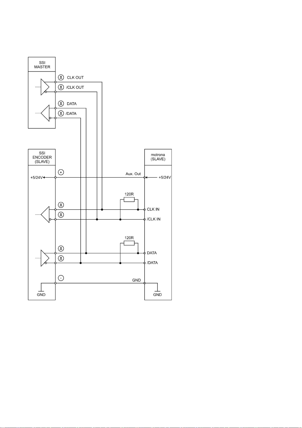
Continuation „SSI-Absolute encoder input (X2)“:
Connection for MODE Slave:
9085_5010_04a_oi_e.docx / Feb-21 page 15 / 72
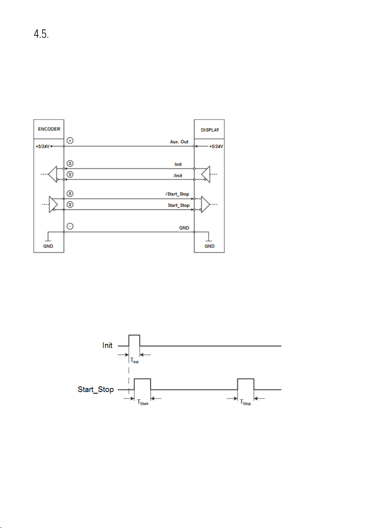
Start-stop encoder inputs (X2)
At terminal X2 - Pin 1+2 the RS422 connection for the init pulse in "MODE MASTER" is available.
(Device generates Init pulse itself!).
At terminal X2 - Pin 5+6 the RS422 connection for the init pulse in "MODE SLAVE" is available. (Init
pulse is generated by an external device!).
At terminal X2 - Pin 3 + 4 the RS422 connection for the Sart-Stop pulse is available.
Connection of the RS422 signals:
DPI measurement operation
In the "MODE MASTER", the init pulse is sent to the position sensor on the init line at regular
intervals (SAMPLING TIME (ms)), whose rising edge triggers a measurement.
The pulse width of the init pulse can be set by means of the "INIT PULSE TIME (µs)" parameter.
T
: 1…9 µs (adjustable)
Init
T
: ~3…5 µs
Start
T
: ~3…5 µs
Stop
9085_5010_04a_oi_e.docx / Feb-21 page 16 / 72
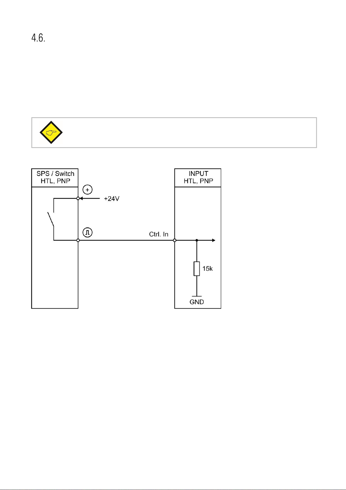
Note: With an HTL pulse (rising edge) on Ctrl. In 6, the device is reset to the factory
settings.
Control Inputs (X5)
At terminal X5 pins 2,3,4,5,6 and 7 there are six control inputs with HTL PNP characteristic available.
Control Input 1 (Ctrl. In 1) to Control Input 5 (Ctrl. In 5) are freely configurable in the COMMAND
MENU and are used for functions to be triggered externally. eg. for releasing the latching, resetting
the measurement result or for teaching the preset values or the analog output.
Control input 6 (Ctrl. In 6) is used exclusively for resetting the device parameters to the "default"
values. Thus, it is not freely configurable.
Wiring of the control inputs:
Unconnected control inputs are always “LOW”.
All inputs are designed to receive impulses from an electronic impulse source.
Notice for mechanical switching contacts:
When exceptionally mechanical contacts are used, please connect an external capacitor between
GND (-) and the corresponding input (+). A capacity of 10 µF will reduce the input frequency to
20 Hz and miscounting due to contact bouncing will be eliminated.
9085_5010_04a_oi_e.docx / Feb-21 page 17 / 72

Analog output (X4)
Important:
A parallel operation with voltage and current output at the analog output is not allowed.
A 16 bit analog output is available at terminal X4 pin 1, 2 and 3.
This output can be configured and scaled in the ANALOG MENU.
The following configuration is possible:
• Voltage output: -10 … +10 V
• Current output: 0 … 20 mA
• Current output: 4 … 20 mA
The analog output is proportional to the display value and is referenced to potential AGND.
AGND and GND are internally interconnected.
9085_5010_04a_oi_e.docx / Feb-21 page 18 / 72
Serial interface (X3)
Important: Parallel operation of RS232 and RS485 is not allowed!
The serial USB communication is done with a baud rate of "
115200 Baud
" and a serial data
format of "
8none1
" and cannot be changed by the user!
A serial interface (RS232 or RS485) is available at terminal X3.
This interface can be configured in the SERIAL MENU.
The serial interface RS232 or RS485 can be used:
for easy setup and commissioning of the units
to modify settings and parameters during operation
to read out internal states and actual measuring values by PC or PLC
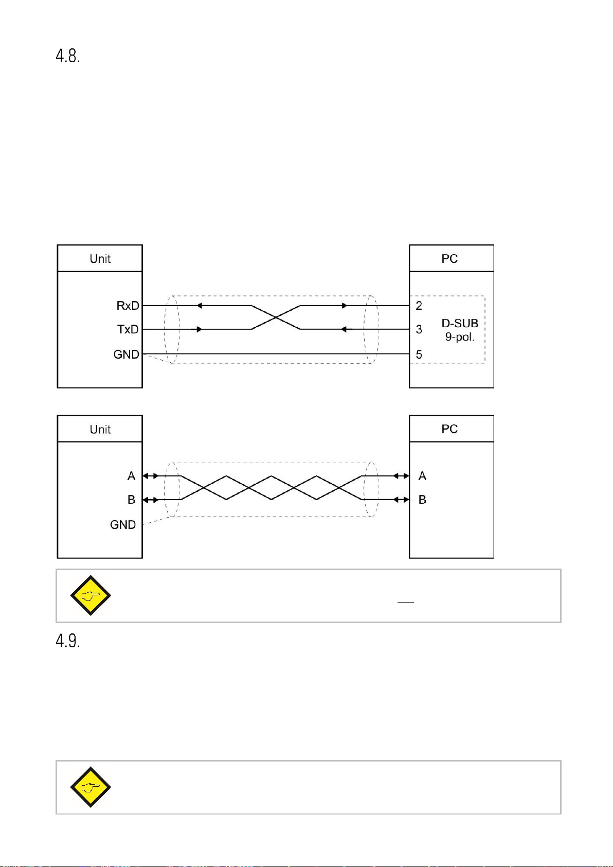
The following drawing shows the connection to a PC by using a standard Sub-D-9 connector:
Connection of the RS232 interface:
Connection of the RS485-interface:
USB interface (X7)
A serial USB interface (mini USB) is available at X7.
The USB interface can be used as follows:
For parameterization of the device during commissioning
To change parameters during operation
For reading out actual values via PC
9085_5010_04a_oi_e.docx / Feb-21 page 19 / 72
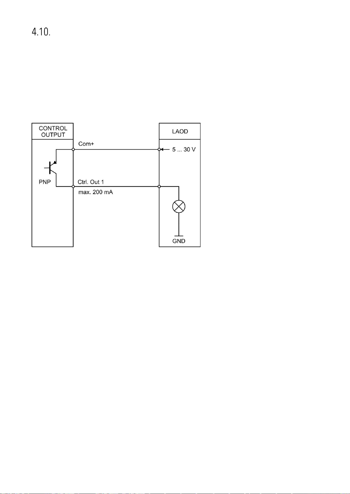
Control outputs (X6)
Six control outputs are available at terminal X6 pin 2, 3, 4, 5, 6 and 7.
Switching conditions can be set in the PRESELECTION MENU. The output Ctrl. Out1 – 6 are fast PNP
outputs with a switching capability of 5 – 30 Volt / 200 mA per channel.
The switching voltage of the outputs must be applied to input terminal X6 pin 1 (COM+).
In case of switching inductive loads it is advisable to use external filtering of the coils.
Wiring of the control-outputs:
9085_5010_04a_oi_e.docx / Feb-21 page 20 / 72

Parameter / Overview-Menu Structure
Menu / Parameter
GENERAL MENU
MODE
ENCODER PROPERTIES
ENCODER DIRECTION
FACTOR
DIVIDER
ADDITIVE VALUE
LINEARIZATION MODE
BACKUP MEMORY
FACTORY SETTINGS
MODE FREQUENCY
FREQUENCY MODE
FREQUENCY BASE
SAMPLING TIME 1 (S)
WAIT TIME 1(S)
STANDSTILL TIME 1 (S)
AVERAGE FILTER 1
SAMPLING TIME 2 (S)
WAIT TIME 2(S)
AVERAGE FILTER 2
MODE COUNTER
COUNT MODE
FACTOR A
SET VALUE A
FACTOR B
SET VALUE B
ROUND LOOP VALUE
Menu / Parameter
MODE SSI
SSI MODE
ENCODER RESOLUTION
DATA FORMAT
BAUD RATE
SSI ZERO
HIGH BIT
LOW BIT
SSI OFFSET
ROUND LOOP VALUE
SAMPLING TIME (S)
ERROR BIT
ERROR POLARITY
MODE START/STOP
INIT MODE
SAMPLING TIME (ms)
INIT PULSE TIME (µs)
VELOCITY (m/s)
OPERATIONAL MODE
OFFSET
CIRCUMFERENCE (mm)
ROUND LOOP VALUE
AVERAGE FILTER - POSITION
STANDSTILL TIME (s)
AVERAGE FILTER - SPEED
PRESELECTION VALUES
PRESELECTION 1
PRESELECTION 2
PRESELECTION 3
PRESELECTION 4
PRESELECTION 5
PRESELECTION 6
The parameterization of the device is realized via the serial interface with a PC and the operating
software OS. The link to the free download can be found on page 2.
This section provides an overview of the menus and their parameters. The menu names are printed
bold and the associated parameters are listed under the menu name.
9085_5010_04a_oi_e.docx / Feb-21 page 21 / 72

Continuation „Parameter / menu structure“:
Menu / Parameter
PRESELECTION 1 MENU
MODE 1
HYSTERESIS 1
PULSE TIME 1 (S)
OUTPUT TARGET 1
OUTPUT POLARITY 1
OUTPUT LOCK 1
START UP DELAY 1 (S)
PRESELECTION 2 MENU
MODE 2
HYSTERESIS 2
PULSE TIME 2 (S)
OUTPUT TARGET 2
OUTPUT POLARITY 2
OUTPUT LOCK 2
START UP DELAY 2 (S)
PRESELECTION 3 MENU
MODE 3
HYSTERESIS 3
PULSE TIME 3 (S)
OUTPUT TARGET 3
OUTPUT POLARITY 3
OUTPUT LOCK 3
START UP DELAY 3 (S)
PRESELECTION 4 MENU
MODE 4
HYSTERESIS 4
PULSE TIME 4 (S)
OUTPUT TARGET 4
OUTPUT POLARITY 4 (S)
OUTPUT LOCK 4
START UP DELAY 4 (S)
PRESELECTION 5 MENU
MODE 5
HYSTERESIS 5
PULSE TIME 5 (S)
OUTPUT TARGET 5
OUTPUT POLARITY 5
OUTPUT LOCK 5
START UP DELAY 5 (S)
Menu / Parameter
PRESELECTION 6 MENU
MODE 6
HYSTERESIS 6
PULSE TIME 6 (S)
OUTPUT TARGET 6
OUTPUT POLARITY 6
OUTPUT LOCK 6
START UP DELAY 6 (S)
SERIAL MENU
UNIT NUMBER
SERIAL BAUD RATE
SERIAL FORMAT
SERIAL INIT
SERIAL PROTOCOL
SERIAL TIMER (S)
SERIAL VALUE
MODBUS
ANALOG MENU
ANALOG FORMAT
ANALOG START
ANALOG END
ANALOG GAIN (%)
ANALOG OFFSET (%)
9085_5010_04a_oi_e.docx / Feb-21 page 22 / 72
 Loading...