

Page 1

ASTRO
®
XTS
TM
5000
Digital Portable Radio
Model III
User Guide
Page 2

Page 3

ASTRO® XTS™ 5000
C
n
Digital Portable Radio, Model III
Quick Reference Card
Product Safety and RF Exposure Compliance
Before using this product, read the operating instructions
for safe usage contained in the Product Safety and RF
!
Exposure booklet enclosed with your radio.
a u t i o
This radio is restricted to occupational use only to satisfy FCC RF
energy exposure requirements. Before using this product, read the
RF energy awareness information and operating instructions in the
Product Safety and RF Exposure booklet enclosed with your radio
(Motorola Publication part number 68P81095C98) to ensure
compliance with RF energy exposure limits.
On/Off/
Volume Knob
Top Side
Button
_ _ _ _ _ _ _
Side Button 1
_ _ _ _ _ _ _
Side Button 2
_ _ _ _ _ _ _
PTT Button
4-Way
Navigation
Button
Home Button
ATTENTION!
Concentric
Switch
_ _ _ _ _ _
16-Position
Select Knob
_ _ _ _ _ _ _
Top Button
_ _ _ _ _ _ _
3-Position
Switch
_ _ _ _ _ _ _
Speaker/Mic
Display
Menu Select
Buttons
App Button
(TMS Button)
Keypad
Radio On/Off
1On - On/Off/Volume knob clockwise.
2Off - On/Off/Volume knob counterclockwise.
Zones/Channels
1 Zone - Zone switch to desired zone.
2 Channel - Channel switch to desired channel.
Receive/Transmit
1 Radio on and select zone/channel.
2 Listen for a transmission.
- or -
Press and hold Volume Set button.
- or -
Press Monitor button and listen for activity.
3 Adjust volume, if necessary.
4Press PTT to transmit; release to receive.
Send Emergency Alarm
Radio on and press Emergency button.
Display shows current zone/channel, and
EMERGENCY. Red LED lights; you hear short,
medium-pitched tone.
Note: To exit emergency at any time, press
and hold Emergency button.
When acknowledgment is received, you hear
four beeps; alarm ends; radio exits emergency.
Send Emergency Call
1 Radio on and press Emergency button.
Note: To exit emergency at any time, press
and hold Emergency button.
2 Press and hold PTT. Announce your
emergency into the microphone.
3 Release PTT to end call.
4 Press and hold Emergency button to exit
emergency.
Send Silent Emergency Alarm
1 Radio on and press Emergency button.
Display does not change; you see no LED;
you hear no tone.
Note: To exit emergency at any time, press
and hold Emergency button.
2 Silent emergency continues until you:
• Press and hold Emergency button to exit
emergency state.
- or -
• Press and release PTT to exit silent
emergency and enter regular emergency
(alarm, call, or alarm with call).
Write your radio’s programmed features on the dashed lines.
Page 4

Display Status Symbols Menu Entries (Use With Menu Navigation)
Receiving an individual call
m
The radio is in the view or program mode;
p
On Steady = view mode; Blinking =
program mode
Received signal strength for the current
s
site (trunking only). The more stripes in the
symbol, the stronger the signal.
Blinks when the battery is low.
b
You are talking directly to another radio or
r
through a repeater; On = direct;
Off = repeater
This channel is being monitored.
C
Your radio is in secure operation;
c
On = secure operation;
Off = clear operation; Blinking = receiving
an encrypted voice call
The radio is scanning a scan list
T
Priority 1 Channel during scan
S
Priority 2 Channel during scan
S
Entry Menu Selection Page
BATT Smart Battery 16
CALL Private Call /Selective Call 59/63
CHAN Select a Channel 22
CLCK Set the Time and Date 95
DIR Repeater/Direct 74
ERAS Key Zeroization 82
KEY Key Selection 79
KSET Keyset Selection 80
LOGF Radio Lock 31
MUTE Keypad Mute 32
NAME Text Select 42
NUM Number Select 41
LOC Location 97
Menu Navigation
U to find Menu Entry
Indicates status of the location signal;
Off = Location feature disabled, or
insufficient battery power in location
accessory device; Blinking = Location
feature enabled, but no location signal
available; On = Location feature enabled,
and location signal available
D, or E, or F directly below
Menu Entry to select
h to exit
Entry Menu Selection Page
PAGE Call Alert Page 67
PHON Phone 55
PROG Editing 41
PSWD Password 30
PWR TX Power Level 27
REKY Rekey Request 85
RPGM Reprogram Request 88
SCAN Scan On/Off 51
SITE Site Lock/Unlock 92
STS Status Call 72
TGRP Talkgroup Call 70
TMS Text Messaging 111
USER User Login 105
VIEW View a List 40
ZONE Select a Zone 21
V or U to scroll through sub-list
D, or E, or F directly below
Menu Entry to select
Page 5

Motorola, Inc.
1301 E. Algonquin Rd.
Schaumburg, IL 60196-1078 U.S.A.
ASTRO® XTS™ 5000
Digital Portable Radio
Model III
User Guide
6881094C27-J
Page 6

This declaration is applicable to your radio only if your radio is labeled
with the FCC logo shown below.
DECLARATION OF CONFORMITY
Per FCC CFR 47 Part 2 Section 2.1077(a)
Responsible Party
Name: Motorola, Inc.
Address: 8000 West Sunrise Boulevard
Plantation, FL 33322 USA
Phone Number: 1-888-567-7347
Hereby declares that the product:
Model Name: XTS 5000
conforms to the following regulations:
FCC Part 15, subpart B, section 15.107(a), 15.107(d) and section 15.109(a)
Class B Digital Device
As a personal computer peripheral, this device complies with Part 15 of the FCC
Rules. Operation is subject to the following two conditions:
1. this device may not cause harmful interference, and
2. this device must accept any interference received, including interference that
may cause undesired operation.
Note: This equipment has been tested and found to comply with the limits for a
Class B digital device, pursuant to part 15 of the FCC Rules. These limits are
designed to provide reasonable protection against harmful interference in a
residential installation. This equipment generates, uses and can radiate radio
frequency energy and, if not installed and used in accordance with the
instructions, may cause harmful interference to radio communications.
However, there is no guarantee that interference will not occur in a particular
installation.
If this equipment does cause harmful interference to radio or television reception,
which can be determined by turning the equipment off and on, the user is
encouraged to try to correct the interference by one or more of the following
measures:
• Reorient or relocate the receiving antenna.
• Increase the separation between the equipment and receiver.
• Connect the equipment into an outlet on a circuit different from that to which
the receiver is connected.
• Consult the dealer or an experienced radio/TV technician for help.
Page 7

Product Safety and RF Exposure Compliance
C
n
Before using this product, read the operating instructions for safe
usage contained in the Product Safety and RF Exposure booklet
!
a u t i o
enclosed with your radio.
ATTENTION!
This radio is restricted to occupational use only to satisfy FCC RF energy
exposure requirements. Before using this product, read the RF energy
awareness information and operating instructions in the Product Safety and RF
Exposure booklet enclosed with your radio (Motorola Publication part number
68P81095C98) to ensure compliance with RF energy exposure limits.
Computer Software Copyrights
The Motorola products described in this manual may include copyrighted Motorola
computer programs stored in semiconductor memories or other media. Laws in the
United States and other countries preserve for Motorola certain exclusive rights for
copyrighted computer programs, including, but not limited to, the exclusive right to copy
or reproduce in any form the copyrighted computer program. Accordingly, any
copyrighted Motorola computer programs contained in the Motorola products described
in this manual may not be copied, reproduced, modified, reverse-engineered, or
distributed in any manner without the express written permission of Motorola.
Furthermore, the purchase of Motorola products shall not be deemed to grant either
directly or by implication, estoppel, or otherwise, any license under the copyrights,
patents or patent applications of Motorola, except for the normal non-exclusive license
to use that arises by operation of law in the sale of a product.
Documentation Copyrights
No duplication or distribution of this document or any portion thereof shall take place
without the express written permission of Motorola. No part of this manual may be
reproduced, distributed, or transmitted in any form or by any means, electronic or
mechanical, for any purpose without the express written permission of Motorola.
Disclaimer
The information in this document is carefully examined, and is believed to be entirely
reliable. However, no responsibility is assumed for inaccuracies. Furthermore, Motorola
reserves the right to make changes to any products herein to improve readability,
function, or design. Motorola does not assume any liability arising out of the
applications or use of any product or circuit described herein; nor does it cover any
license under its patent rights, nor the rights of others.
MOTOROLA, the Stylized M Logo and ASTRO are registered in the U.S. Patent &
Trademark Office. All other product or service names are the property of their
respective owners.
P25 radios contain technology patented by Digital Voice Systems, Inc.
© Motorola, Inc. 2003. All Rights Reserved. Printed in the U.S.A. 9/06.
Page 8

Notes
Page 9

Contents
General Radio Operation . . . . . . . . . . . . . . . . . . . . . . . 1
Notations Used in This Manual ......................................................... 1
Your XTS 5000 Model III Radio ......................................................... 2
Physical Features of the XTS 5000 Model III Radio ......................... 3
Programmable Controls .................................................................... 3
Display .............................................................................................. 4
Keypad .............................................................................................. 9
LED Indicators ................................................................................ 10
Alert Tones ...................................................................................... 11
Standard Accessories .....................................................................14
Radio On and Off ............................................................................ 20
Zones and Channels ....................................................................... 21
Receive / Transmit ..........................................................................24
Common Radio Features . . . . . . . . . . . . . . . . . . . . . . 27
Selectable Power Level ................................................................... 27
Radio Lock ...................................................................................... 29
Mute or Unmute Keypad Tones .......................................................32
Conventional Squelch Operation .................................................... 33
PL Defeat ........................................................................................ 34
Time-out Timer ................................................................................ 35
Emergency ...................................................................................... 36
Lists .................................................................................................40
Scan ................................................................................................51
Telephone Calls (Trunking Only) ..................................................... 54
Private Calls (Trunking Only) .......................................................... 58
Selective Calls (ASTRO Conventional Only) .................................. 62
Call Alert Paging ............................................................................. 65
Conventional Talkgroup Calls (Conventional Operation Only) ........ 70
Status Calls (ASTRO 25 Trunking Only) .........................................72
Repeater or Direct Operation .......................................................... 74
Smart PTT (Conventional Only) ...................................................... 76
Special Radio Features. . . . . . . . . . . . . . . . . . . . . . . . 77
Secure Operations .......................................................................... 77
Digital PTT ID .................................................................................. 86
View Your Radio’s ID Number ......................................................... 87
Dynamic Regrouping (Trunking Only) ............................................. 88
Trunking System Controls ...............................................................91
Time and Date ................................................................................. 95
ASTRO XTS 5000 Model III v
Page 10

Contents
Outdoor Location (using GPS) ........................................................97
ARS User Login and Text Messaging Features. . . 103
Automatic Registration Service (ARS) ...........................................103
ARS User Login Feature ...............................................................105
Text Messaging .............................................................................. 111
Helpful Tips . . . . . . . . . . . . . . . . . . . . . . . . . . . . . . . . 125
Radio Care ....................................................................................125
Service ...........................................................................................127
Battery ...........................................................................................128
Antenna .........................................................................................131
Accessories. . . . . . . . . . . . . . . . . . . . . . . . . . . . . . . . 133
Antennas .......................................................................................133
Batteries and Battery Accessories .................................................133
Carry Accessories .........................................................................134
Chargers ........................................................................................135
Surveillance Accessories ...............................................................136
Switches ........................................................................................139
Vehicular Adapters ........................................................................139
Appendix: Maritime Radio Use in the VHF Frequency
Range. . . . . . . . . . . . . . . . . . . . . . . . . . . . . . . . . . . . . 141
Special Channel Assignments .......................................................141
Operating Frequency Requirements .............................................142
Glossary . . . . . . . . . . . . . . . . . . . . . . . . . . . . . . . . . . 145
Commercial Warranty. . . . . . . . . . . . . . . . . . . . . . . . 151
Index . . . . . . . . . . . . . . . . . . . . . . . . . . . . . . . . . . . . . 157
vi
Page 11

General Radio Operation
W
G
!
C
n
Notations Used in This Manual
Throughout the text in this publication, you will notice the use of
WARNING, Caution, and Note. These notations are used to
emphasize that safety hazards exist, and the care that must be taken
or observed.
An operational procedure, practice, or condition,
!
!
A R N I N
a u t i o
Note: An operational procedure, practice, or condition,
etc., which may result in injury or death if not
carefully observed.
An operational procedure, practice, or condition,
etc., which may result in damage to the equipment
if not carefully observed.
etc., which is essential to emphasize.
The following special notations identify certain items:
Example Description
Light button or D Buttons and keys are shown in bold print or
as a key symbol.
PHONE CALL
PHONE Menu entries are shown similar to the way
Press U This means “Press the right side of the
ASTRO XTS 5000 Model III 1
Information appearing on the radio’s
display is shown using the special display
font.
they appear on the radio’s display.
4-way Navigation button.”
Page 12
General Radio Operation
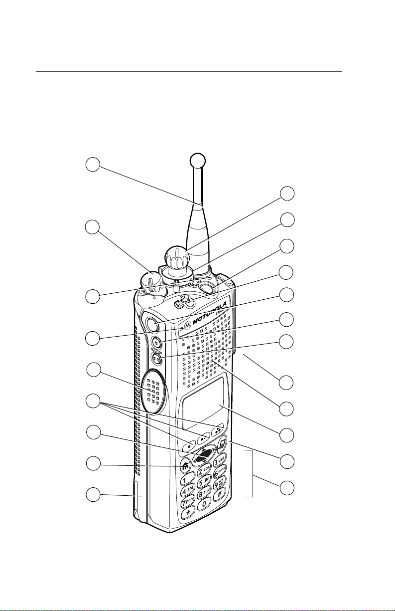
Your XTS 5000 Model III Radio
1
21
2
3
4
5
6
7
8
9
20
19
18
17
16
15
14
13
12
11
10
MAEPF-27193-A
2
Page 13
General Radio Operation
Physical Features of the XTS 5000 Model III
Radio
Table 1: Physical Features
No. Feature Page No. Feature Page
1 Antenna 17 8 Home Button 8
2 On/Off/Volume Control
Knob
3 LED 10 10 Keypad 9
4 Microphone 11 App Button 9
5 PTT (Push-to-Talk)
Button
6 Menu Select Buttons 7 13 Speaker
7 4-Way Navigation
Button
20 9 Battery 14
12 Display 4
9 14 Universal Connector 19
Programmable Controls
The following radio controls can be programmed to operate certain
software-activated features.
No. Feature No. Feature
15 Side Button 2 19 Top Button
16 Side Button 1 20 2-Position Concentric Switch
17 Top Side (Select) Button 21 16-Position Select Knob
18 3-Position A/B/C Switch
The features that can be assigned to these controls by a qualified
radio technician, and the pages where these features can be found
are listed in Table 2 on page 4.
Any references in this manual to controls that are
“preprogrammed” mean that a qualified radio technician must
use the radio’s programming software to assign a feature to a
control.
ASTRO XTS 5000 Model III 3
Page 14
General Radio Operation
Table 2: Programmable Features
Feature Page Feature Page Feature Page
Call Alert 65 PL Defeat 34 Site Search 94
Call Response 59 Private Call 58 Smart Battery 16
Channel 22 Repeater/Direct 75 Status 73
Dynamic Priority 53 Reprogram
Request
Emergency 36 Scan List
Programming
Keypad Mute 32 Scan On/Off 51 TX Power Level 28
Light 5 Secure/Clear 77 User Login 103
Monitor 25 Select 45 Volume Set 24
Nuisance Delete 52 Selective Call 62 Zone 21
Phone 54 Site Lock/
Unlock
89 Text Messaging 111
47 TMS Quick Text 120
92
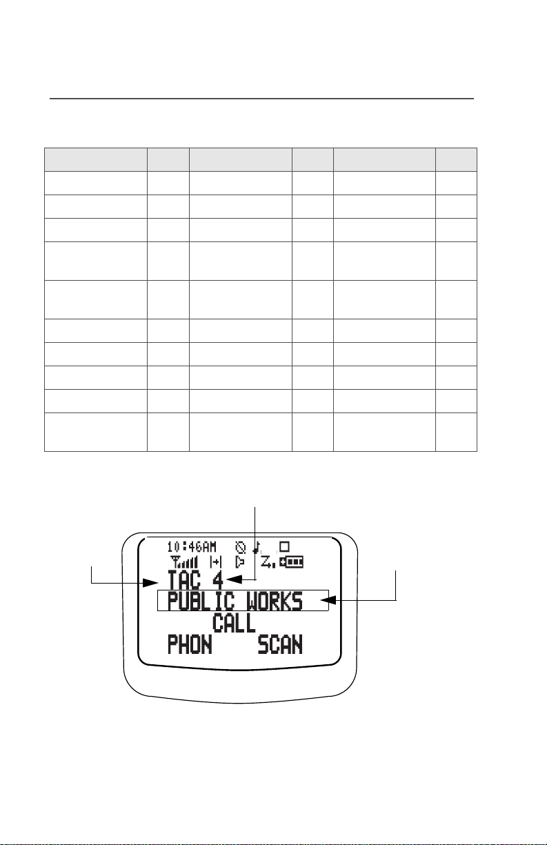
Display
channel
zone
Radio alias
The above screen is typical of what you will see on your radio. The
64 x 96 pixel liquid crystal display (LCD) shows radio status, text, and
menu entries.
4
Page 15

General Radio Operation
Backlight
If poor light conditions make the display, keypad, or channel numbers
(around the 16-Position Select knob) difficult to read, turn on the
radio’s backlights by pressing the preprogrammed Light button.
These lights will remain on for a preprogrammed time before they turn
off automatically, or you can turn them off immediately by pressing the
Light button again.
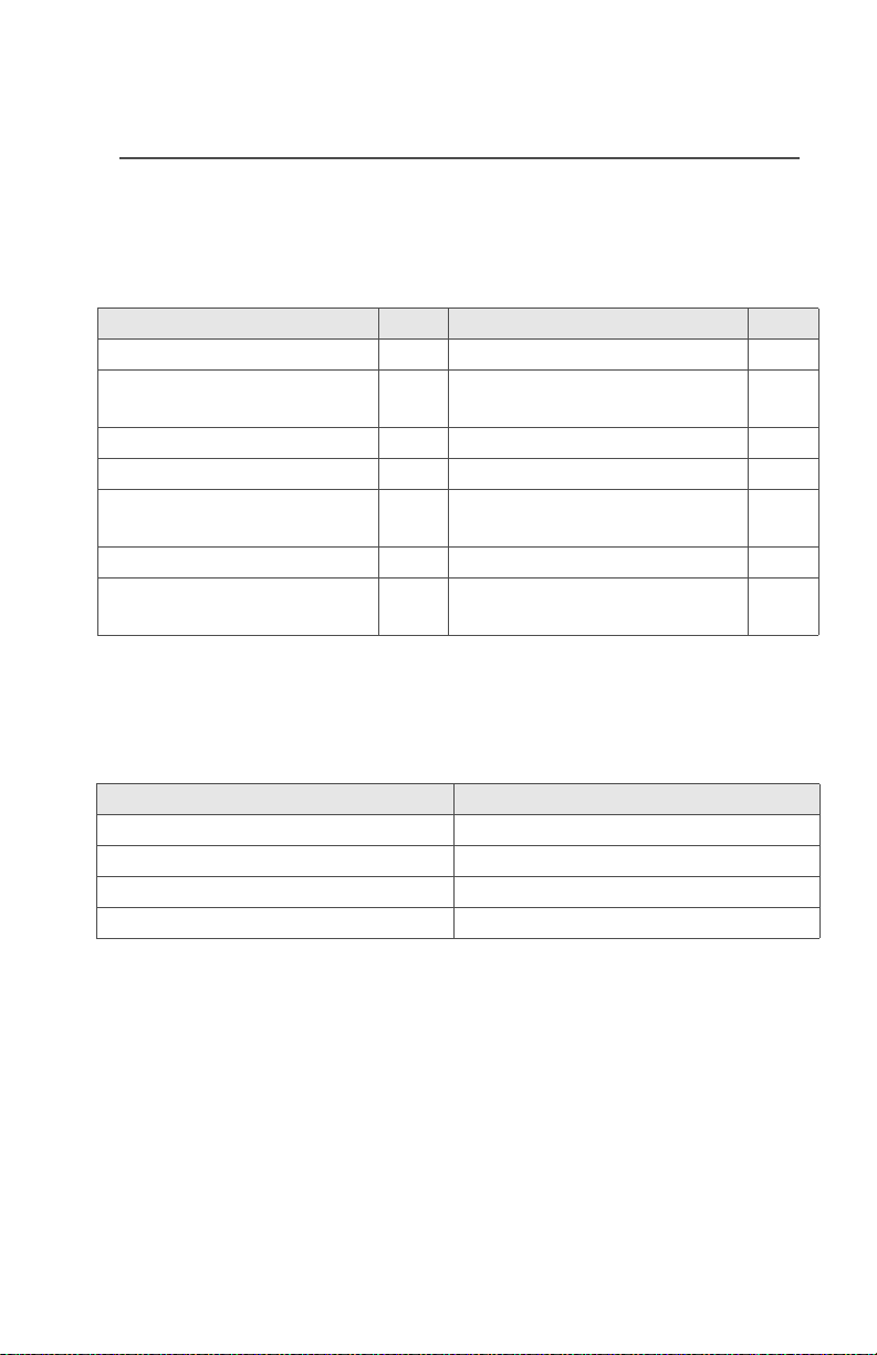
Status Symbols
The top two display rows contain symbols that indicate radio
operating conditions.
Table 3: Status Symbols
Symbol Indication Page No.
m
p
p
s
b
Call Received
Blinks when an Individual Call is
received.
View/Program Mode
The radio is in the view or program mode.
• On steady = view mode
• Blinking = program mode
Received Signal Strength Indication
(RSSI)
The received signal strength for the
current site, for trunking only. The more
stripes in the symbol, the stronger the
signal.
Battery
• Conventional = blinks when battery is
low
• Smart = the number of bars (0-3)
shown indicates the charge remaining
in your battery; blinks when battery is
low
55, 59,
62, 66
40-45,
47, 48
94
129
ASTRO XTS 5000 Model III 5
Page 16

General Radio Operation
Table 3: Status Symbols (Continued)
Symbol Indication Page No.
Talkaround
• On = you are talking directly to
r
another radio, not through a repeater,
during conventional operation only
• Off = you are talking through a
repeater
74
C
c
c
T
S
(Dot
Blinking)
S
(Dot Steady)
Monitor (Carrier Squelch)
The selected channel is being monitored
during conventional operation only.
Secure Operation
• On = secure operation
• Off = clear operation
• Blinking = receiving an encrypted
voice call
Scan
The radio is scanning a scan list.
Priority-One Channel Scan
One channel is assigned as the priority
channel during scan operation.
Priority-Two Channel Scan
Two channels are assigned as the priority
channels during scan operation.
Location Signal
• Off = Location feature disabled, or
insufficient battery power in location
accessory device;
• Blinking = Location feature enabled,
but no location signal available;
•On = Location feature enabled, and
location signal available
26, 33,
34
77
44, 46-51
44, 46-50
44, 46-50
97-98
6
Page 17

General Radio Operation
Table 3: Status Symbols (Continued)
Symbol Indication Page No.
User Login Indicator (IP Packet Data)
• On (Tinted) = User is currently
associated with the radio;
• Off (Not tinted) = User is currently not
associated with the radio;
• Blinking = Device registration or user
registration with the server failed due
to an invalid username or pin.
108-108
Menu Entry (Softkey)
The bottom row of the display contains one to three menu entries
(also known as softkeys). The menu entries allow you to select one of
several menus to access the radio’s features. The menu entries are
accessed through the Menu Select buttons.
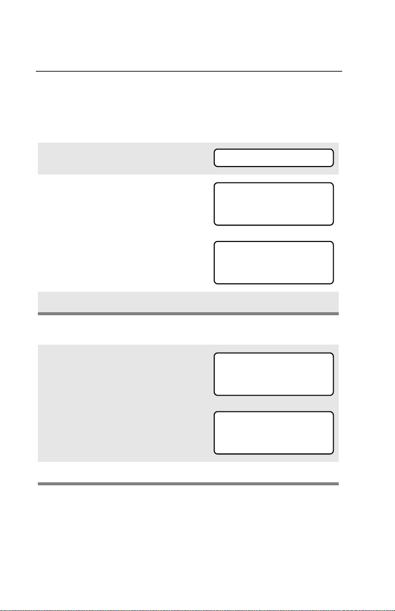
Menu Select Buttons
The Menu Select buttons access the menu entries of features that
have been activated by a qualified radio technician. Your radio may
be programmed differently from the following example, but the display
for turning Scan on or off might look like the example below. For
instance, to turn Scan on, press D directly below ON.
SCAN
menu entry
(softkey)
Home
Button
ASTRO XTS 5000 Model III 7
ON OFF
4-Way Navigation
Button
T
menu entry
(softkey)
3 Menu Select
Buttons
App
Button
(TMS Button)
Page 18

General Radio Operation
Menu Entry Features
Table 4: Menu Entries
Feature
Smart Battery
Private Call /
Selective Call
Channel Selection
Time/Date
Repeater/Direct
Key Zeroization
Key Selection
Keyset Selection
Radio Lock
Keypad Mute
Text Select
Number Select
Call Alert Page
Text Messaging
Menu
Entry
BATT
CALL
CHAN
CLCK
DIR
ERAS
KEY
KSET
LOGF
MUTE
NAME
NUM
PAGE
TMS
Page Feature
16 Phone
59/63 Editing
22 Password
95 TX Power Level
74 Rekey Request
82 Reprogram
Request
79 Scan On/Off
80 Site Lock/Unlock
31 Status Call
32 Talkgroup Call
42 View a List
41 Zone Selection
67 Location
111 User Login
Menu
Entry
PHON
PROG
PSWD
PWR
REKY
RPGM
SCAN
SITE
STS
TGRP
VIEW
ZONE
LOC
USER
Page
55
41
30
27
85
88
51
92
72
70
40
21
97
103
Home Button
The Home button always returns you to the home (default) display. In
most cases, this is the current mode.
Some radio features that you can edit require saving information in
memory. Pressing the Home button after editing those features
causes information to be saved before going to the home display.
Some features do not require you to press the Home button to go to
the home display. This reduces the required number of key presses.
8
Page 19

General Radio Operation
App Button (TMS Feature Button)
This button brings you to the Text Messaging Service (TMS) feature
screen.
4-Way Navigation Button
This button is used to scroll through the radio’s lists or items in the
display, or both.
Keypad
The 3 x 4-key alphanumeric keypad
provides an interface to your radio’s
features.
The keypad functions in a manner
similar to a standard telephone keypad
when entering numeric digits.
When the keypad is used to edit a list,
each key can generate different
characters of the alphabet. Refer to
MAEPF-27194-A
Table 5, below, for a complete list of
characters.
Table 5: Keypad Characters
Number of times the key is pressed
Key
1 2 3 4 5 6 7 8 9
0
1
2
3
4
5
6
0()<>
1&%
ABC2abc
DEF3def
GHI 4gh i
JKL5 j k l
MNO 6mn o
ASTRO XTS 5000 Model III 9
Page 20

General Radio Operation
Table 5: Keypad Characters (Continued)
Key
7
8
9
*
#
1 2 3 4 5 6 7 8 9
PQRS7pq r s
TUV8 t uv
WXYZ9wxyz
*/+-=
#. !?, ;
Number of times the key is pressed
LED Indicators
The LED on top of the radio indicates the radio’s operating status:
Table 6: LED Indicators
LED Indicator What it Means
Red Radio transmitting
Blinking red • Channel busy, or
• Low battery (while transmitting)
Double blinking red Receiving encrypted audio
Blinking green Receiving an individual call
10
Page 21

General Radio Operation
Alert Tones
An alert tone is a sound or group of sounds. Your radio uses alert
tones to inform you of your radio’s conditions. The following table lists
these tones and when they occur.
Table 7: Alert Tones
You Hear Tone Name Heard
Short,
Low-Pitched
Tone
Long, Low-
Pitched Tone
A Group of
Low-Pitched
Tones
Invalid
Key-Press
Radio Self-Test
Fail
Reject when unauthorized request is
Time-Out Timer
Warning
No ACK
Received
Time-Out Timer
Timed Out
Talk Prohibit/
PTT Inhibit
Out-of-Range (when PTT button is pressed) the
Invalid Mode when radio is on an unprogrammed
Individual Call
Warning Tone
Busy when system is busy
when wrong key is pressed
when radio fails its power-up self
test
made
four seconds before time out
when radio fails to receive an
acknowledgment
after time out
(when PTT button is pressed)
transmissions are not allowed
radio is out of range of the system
channel
when radio is in an individual call
for greater than 6 seconds without
any activity
ASTRO XTS 5000 Model III 11
Page 22

General Radio Operation
Table 7: Alert Tones (Continued)
You Hear Tone Name Heard
Short,
Medium-
Pitched
Tone
Long,
Medium-
Pitched
Tone
A Group of
Medium-
Pitched
Tones
Short,
High-Pitched
Tone (Chirp)
Valid KeyPress
Radio Self-Test
Pass
Clear Voice at beginning of a non-coded
Priority
Channel
Received
Emergency
Alarm Entry
Central Echo when central controller has
Volume Set when volume is changed on a quiet
Emergency Exit when exiting the emergency state
Failsoft when the trunking system fails
Automatic Call
Back
Talk Permit (when PTT button is pressed)
Keyfail when encryption key has been lost
Console
Acknowledge
Received
Individual Call
Call Alert Sent when Call Alert is received by the
Low-Battery
Chirp
when correct key is pressed
when radio passes its power-up
self test
communication
when activity on a priority channel
is received
when entering the emergency state
received a request from a radio
channel
when voice channel is available
from previous request
verifying system accepting
transmissions
when status, emergency alarm, or
reprogram request ACK is received
when Call Alert or Private Call is
received
target radio
when battery is below preset
threshold value
12
Page 23

General Radio Operation
Table 7: Alert Tones (Continued)
You Hear Tone Name Heard
Short,
Medium-
GPS RSM Low
Battery Chirp
when this accessory battery is
below preset threshold value
Pitched
Tone (Chirp)
Fast Ringing when system is searching for target
of Private Call
Ringing
Gurgle
Unique, low-
Enhanced Call
Sent
Phone Call
Received
Dynamic
Regrouping
New Message when a new message is received.
when waiting for target of Private
Call to answer the call
when a land-to-mobile phone call is
received
(when the PTT button is pressed)
a dynamic ID has been received
pitched
chirp
Unique,
high-pitched
Priority
Message
when a priority message is
received.
chirp
ASTRO XTS 5000 Model III 13
Page 24

General Radio Operation
W
G
Standard Accessories
Battery
To avoid a possible explosion:
!
!
A R N I N
Charging the Battery
The Motorola-approved battery shipped with your radio is uncharged.
Prior to using a new battery, charge it for a minimum of 16 hours to
ensure optimum capacity and performance.
For a list of Motorola-authorized batteries available for use with your
XTS 5000 radio, see “Batteries and Battery Accessories” on
page 133.
Note: When charging a battery attached to a radio, turn the radio off
to ensure a full charge.
Battery Charger
To charge the battery, place the battery, with or without the radio, in a
Motorola-approved charger. The charger’s LED indicates the
charging progress; see your charger’s user guide. For a list of
chargers, see “Chargers” on page 135.
• DO NOT replace the battery in any area
labeled “hazardous atmosphere”.
• DO NOT discard batteries in a fire.
14
Page 25

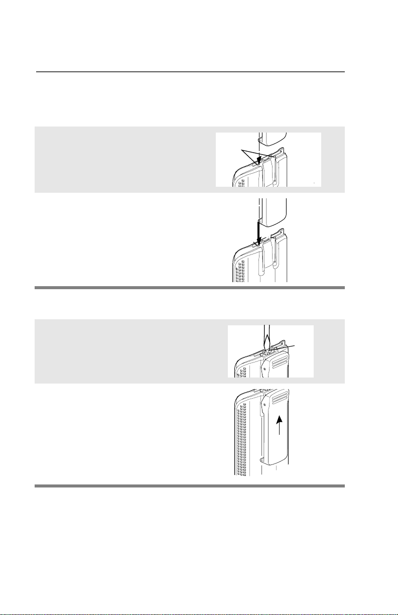
Attach the Battery
1 With the radio turned off,
insert the top edge of the
battery into the radio’s frame
as shown.
2 Rotate the battery toward the
radio and press down until the
battery clicks into place.
Remove the Battery
1 With the radio turned off,
press the release button on
the bottom of the battery until
the battery releases from the
radio.
General Radio Operation
2 Remove the battery from the
radio.
Note: If your radio is programmed with volatile-key retention,
encryption keys will be retained for approximately 30
seconds after battery removal. Consult a qualified radio
technician for details.
ASTRO XTS 5000 Model III 15
Page 26
General Radio Operation
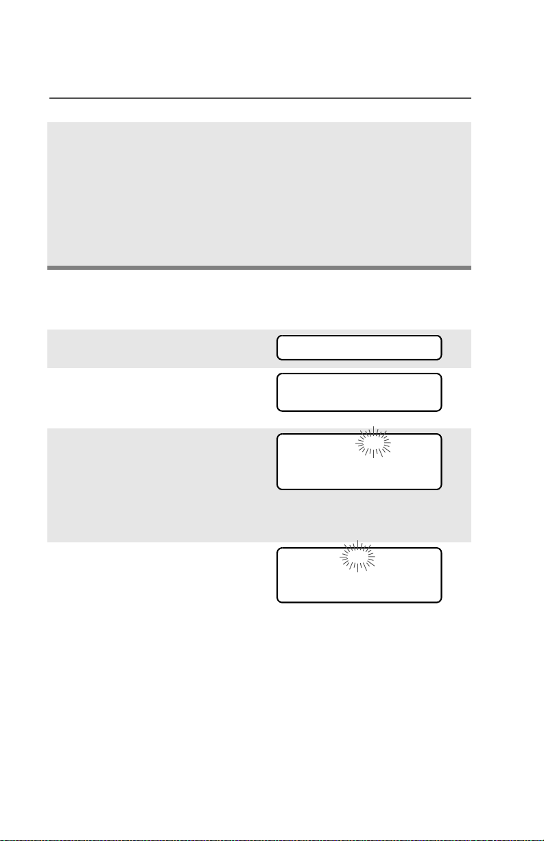
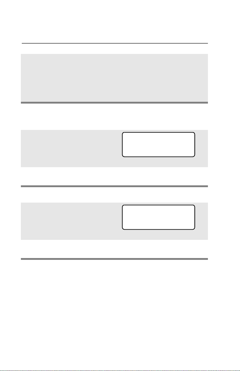
Smart Battery Status
This feature lets you view the status of your Smart Battery.
Use the Menu
1 Press U to find BATT.
2 Press D, E, or F directly
below BATT.
Note: If a Smart Battery is not
powering your radio:
3 Press h to exit.
Use the Preprogrammed Smart Battery Button
1 Press the Smart Battery
button.
Note: If a Smart Battery is not
powering your radio:
BATT
CAPACITY 70%
INIT 10/01
EST CHGS 11
SMART BATT
DATA NOT
AVAILABLE.
CAPACITY 70%
INIT 10/01
EST CHGS 11
SMART BATT
DATA NOT
AVAILABLE.
2 Press h to exit.
16
Page 27

General Radio Operation
Antenna
For information regarding available antennas, see page 131.
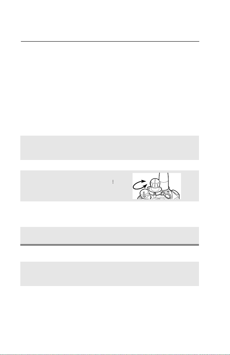
Attach the Antenna
With the radio turned off, turn the
antenna clockwise to attach it to
the radio.
Remove the Antenna
With the radio turned off, turn the
antenna counter-clockwise to
remove it from the radio.
ASTRO XTS 5000 Model III 17
Page 28
General Radio Operation
al
Belt Clip
Attach the Belt Clip
1 Align the grooves of the belt
clip with those of the battery.
2 Press the belt clip downward
until you clear a click.
Remove the Belt Clip
1 Use a flat-bladed object to
press the belt clip tab away
from the battery.
2 Slide the belt clip upward to
remove it.
Grooves
Slots
Slots
Battery
Battery
Battery
Battery
Met
Tab
18
Page 29

General Radio Operation
Universal Connector Cover
The universal connector is located on the antenna side of the radio. It
is used to connect accessories to the radio.
Note: To prevent damage to the connector, shield it with the
connector cover when not in use.
Remove the Universal Connector Cover
1 Insert a flat-bladed
screwdriver into the area
between the bottom of the
cover and the slot below the
connector.
2 Hold the top of the cover with
your thumb while you pry the
bottom of the cover away
from the radio with the
screwdriver.
Attach the Universal Connector Cover
1 Insert the hooked end of the
cover into the slot above the
To p
Hooked End
To p
Slot
connector. Press downward
on the cover’s top to seat it in
the slot.
2 Rub the ball of your thumb
from the top to the bottom of
the cover while applying
pressure towards the radio.
This should flex the cover and
snap it into place.
ASTRO XTS 5000 Model III 19
Page 30

General Radio Operation
O
O
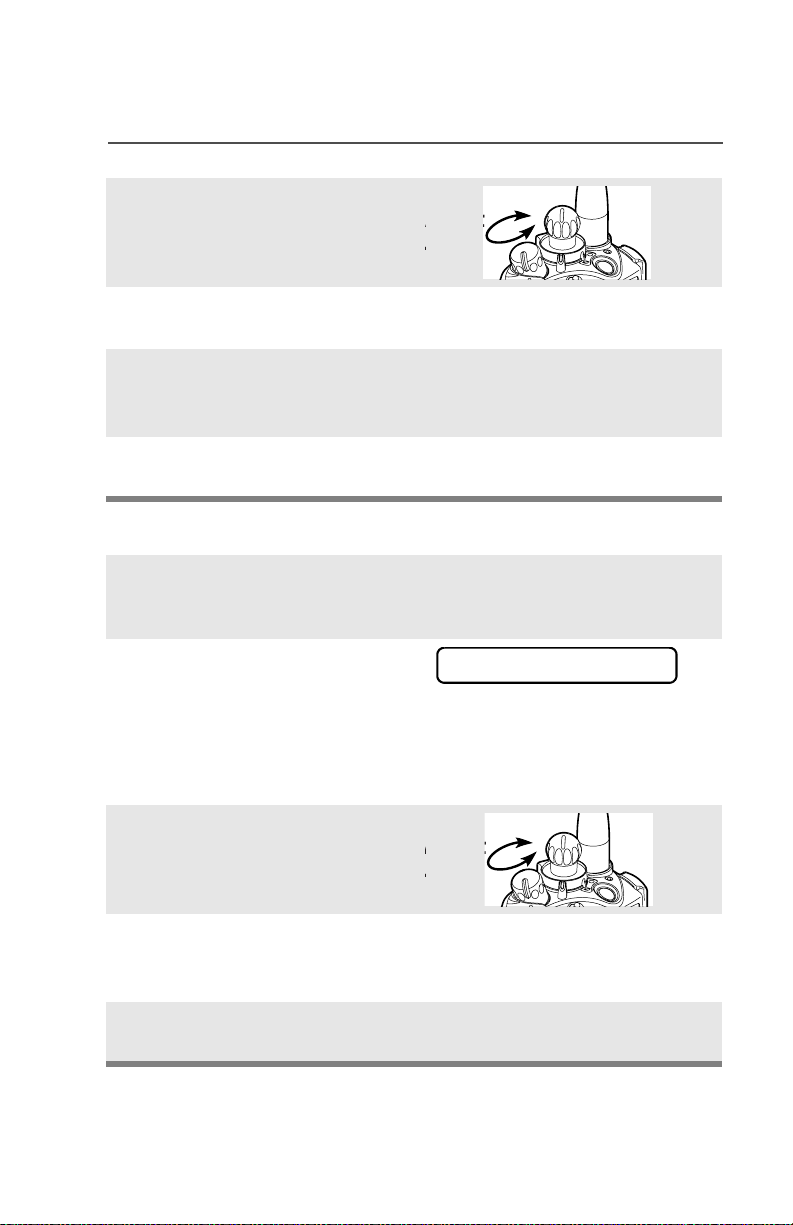
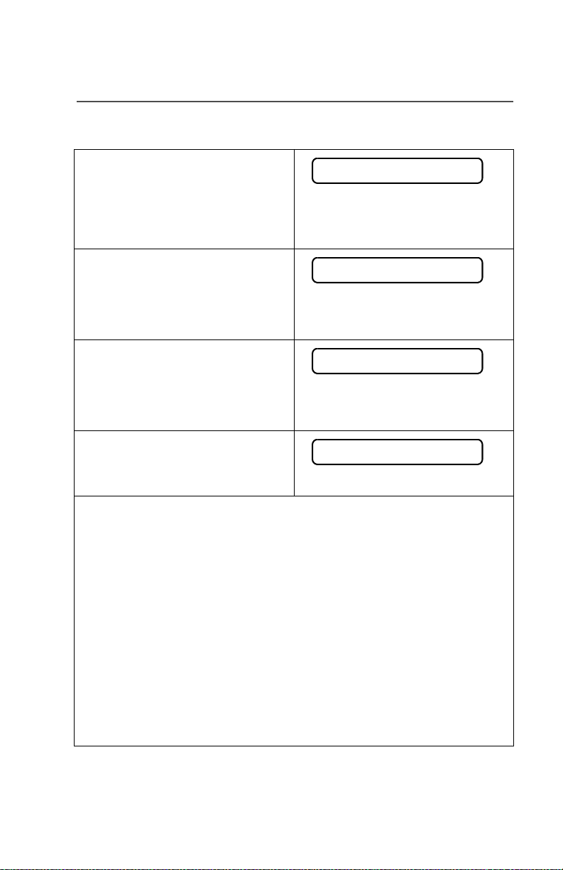
Radio On and Off
Turn the Radio On
Turn the On/Off/Volume Control
knob clockwise.
n
Note: If the power-up test is
successful, you briefly
see SELF TEST, then the
home display.
If the power-up test is
unsuccessful, you see
ERROR XX/YY. (XX/YY is
an alphanumeric code.)
Turn off the radio, check the battery, and turn the radio on. If
the radio fails the power-up test again, record the ERROR XX/
YY code and contact a qualified radio technician.
Turn the Radio Off
Turn the On/Off/Volume Control
knob counterclockwise until it
clicks.
SELF TEST
ERROR XX/YY
ff
20
Page 31

General Radio Operation
Zones and Channels
A zone is a grouping of channels. A channel is a group of radio
characteristics, such as transmit/receive frequency pairs.
Before you use your radio to receive or send messages, you should
select the zone and channel.
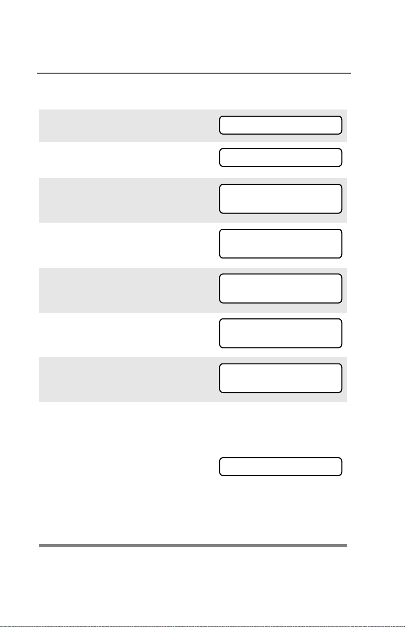
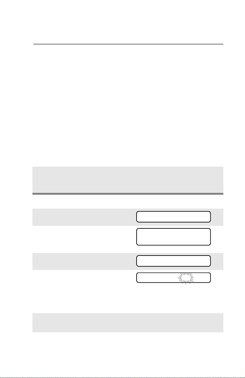
Select a Zone
Use the Menu
1 Press U to find ZONE.
ZONE
2 Press D, E, or F
directly below ZONE.
The current zone (in this
case, POL) blinks and the
channel name (DISP NW),
does not flash.
3 Press U to find the zone
you want. For example,
FIRE.
4 Press h to confirm the
displayed zone and channel.
OR
Press the PTT button to
transmit on the displayed
zone/channel.
Use the Preprogrammed Zone Switch
1 If a control on your radio has
been preprogrammed as the
Zone switch, move the Zone
switch to the position for the
zone you want.
POL DISP NW
FIRE DISP NW
FIRE DISP NW
FIRE DISP NW
FIRE DISP NW
ASTRO XTS 5000 Model III 21
Page 32

General Radio Operation
C
Note: If the zone you selected
is unprogrammed, repeat
step 1.
2 Press h to confirm the
displayed zone and channel.
FIRE DISP NWUNPROGRAMMED
FIRE DISP NW
Select a Channel
Consult a qualified radio technician for the right choice between the
following methods:
Method 1: Use the Preprogrammed 16-Position Select Knob
After the zone you want is
displayed, turn the
16-Position Select knob to
the desired channel.
Method 2: Use the Menu
1 Press U to find CHAN.
Select
hannel
CHAN
2 Press D, E, or F
directly below CHAN.
The display shows the cur-
rent channel name (in this
case, DISP NW) blinking and
the zone (POL), not blinking.
3 Press U to find the channel
name you want.
OR
Use the keypad to enter the
channel number.
22
POL DISP NW
POL DISP SE
Page 33

General Radio Operation
Note: If the channel you
selected is
unprogrammed, repeat
step 3.
4 Press h to confirm the
displayed zone and channel.
OR
Press the PTT button to
transmit on the displayed
zone/channel.
UNPROGRAMMED
POL DISP SE
ASTRO XTS 5000 Model III 23
Page 34
General Radio Operation
L
Receive / Transmit
Radio users who switch from analog to digital radios often assume
that the lack of static on a digital channel is an indication that the radio
is not working properly. This is not the case. Digital technology quiets
the transmission by removing the “noise” from the signal and allowing
only the clear voice or data information to be heard.
This section emphasizes the importance of knowing how to monitor a
channel for traffic before keying up to send a transmission.
Without Using the Volume Set and Monitor Buttons
1 Turn the radio on and select
the desired zone and
channel.
2 Listen for a transmission.
3 Adjust the Volume Control
knob if necessary.
djust
evel
4 Press and hold the PTT
button to transmit. The LED
lights RED while transmitting.
5 Release the PTT button to
receive (listen).
Use the Preprogrammed Volume Set Button
1 Turn the radio on and select
the desired zone and
channel.
2 Press and hold the Volume
Set button to hear the volume
set tone.
24
Page 35
General Radio Operation
3 Adjust the Volume Control
knob if necessary.
just
evel
4 Release the Volume Set
button.
5 Press and hold the PTT
button to transmit. The LED
lights RED while transmitting.
6 Release the PTT button to
receive (listen).
Use the Preprogrammed Monitor Button
1 Turn the radio on and select
the desired zone and
channel.
2 Press the Monitor button
and listen for activity. The
Carrier Squelch indicator is
displayed. (See the following
Conventional Mode
Operation.)
3 Adjust the Volume Control
knob if necessary.
C
just
evel
4 Press and hold the PTT
button to transmit. The LED
lights RED while transmitting.
5 Release the PTT button to
receive (listen).
ASTRO XTS 5000 Model III 25
Page 36

General Radio Operation
Conventional Mode Operation
Your radio may be programmed to receive Private-Line® (PL) calls.
1 Momentarily press the
Monitor button to listen for
activity. The Carrier Squelch
indicator is displayed.
2 Press and hold the Monitor
button to set continuous
monitor operation. (The
duration of the button press is
programmable.)
3 Press the Monitor button
again, or the PTT button, to
return to the original squelch
setting.
Note: If you try to transmit on a receive-only channel, you will hear
an invalid tone until you release the PTT button.
C
26
Page 37

Common Radio Features
Selectable Power Level
This feature lets you select the power level at which your radio will
transmit. The radio will always turn on to the default setting. This
feature must be preprogrammed by a qualified radio technician.
•Select LOW for a shorter transmitting distance and to conserve
power.
•Select HIGH for a longer transmitting distance.
Use the Menu
1 Press U to find PWR.
2 Press D, E, or F
directly below PWR. The display
shows the current power level,
along with LOW and HIGH.
3 Press D, E, or F directly
below the desired power level
(LOW or HIGH).
Note: To exit without changing the setting, press h or the PTT
button.
PWR
HIGH POWER
LOW HIGH
OR
LOW POWER
LOW HIGH
• The new transmit power
level is saved.
• The radio returns to the
home display.
ASTRO XTS 5000 Model III 27
Page 38

Common Radio Features
Use the Preprogrammed Transmit Power Level Switch
1 Move the TX Power Level
switch to the Low Power
position. The power level is set
to Low.
2 Move the TX Power Level
switch to the HIgh Power
position. The power level is set
to High.
28
Page 39

Common Radio Features
Radio Lock
This feature changes your radio to a more robust security system that
protects the use of the secure encryption keys. If this feature is
enabled in your radio by a qualified radio technician, when you turn
the radio on, you see RADIO LOCKED.
Unlock Your Radio
1 Enter your numeric password.
Note:
• Secure-equipped radios — 6 to 8 characters.
• Clear radios — 0 to 8 characters.
If you make a mistake, press V to backspace.
2 Press the preprogrammed
Select button after you enter
your password. If the password
is correct, the radio unlocks.
Note: If the password is incorrect,
the radio remains locked.
• If you enter three incorrect
passwords in a row, you see
DEADLOCK. Turn the radio off
and then on, and begin again at
step 1.
• Secure Radios Only — If you
enter a total of 17 consecutive
incorrect passwords (turning the
radio off and on does not reset
this number), the radio erases
all of its encryption keys and
shows “DEADLOCK.” See a
qualified radio technician.
RADIO LOCKED
DEADLOCK
DEADLOCK
ASTRO XTS 5000 Model III 29
Page 40
Common Radio Features
Change Your Password
1 Press U to find PSWD.
2 Press D, E, or F directly
below PSWD.
3 Enter the old password.
4 Press D, E, or F directly
below SEL.
5 Enter the new password.
6 Press D, E, or F directly
below SEL.
7 Re-enter the new password.
8 Press D, E, or F directly
below SEL. The password is
updated.
PSWD
OLD PASSWORD
SEL
NEW PASSWORD
SEL
SEL
SEL
SEL
Note: If the two passwords do not
match, repeat steps 5
through 8.
Note: If you enter three incorrect old passwords, the radio exits
the password feature. You cannot access this feature again
until you turn the radio off and on.
NEW PASSWORD
30
Page 41

Common Radio Features
Enable or Disable the Radio Lock Feature
(Secure Radios Only)
This feature (programmable by a qualified radio technician) allows
you to enable or disable the radio lock feature.
1 Press U to find LOGF.
2 Press D, E, or F directly
below LOGF. You see the current
state.
3 To enable the radio lock feature,
press D, E, or F directly
below ENAB.
OR
To disable the radio lock feature, press D, E, or F
directly below DSAB.
LOGF
PSWD ENABLD
ENAB DSAB
OR
PSWD DISBLD
ENAB DSAB
ASTRO XTS 5000 Model III 31
Page 42

Common Radio Features
Mute or Unmute Keypad Tones
You can turn the keypad tones on or off.
Use the Menu
1 Press U to find MUTE.
2 Press D, E, or F
directly below MUTE. The
current state is shown.
3 Press D, E, or F
directly below OFF or ON.
Note: Press h or the PTT button to exit without changing the
setting.
MUTE
TONES OFF
OFF ON
OR
TONES ON
OFF ON
Use the Preprogrammed Keypad Mute Button
Press the Keypad Mute
button to turn the tones off or
on.
32
Page 43
Common Radio Features
Conventional Squelch Operation
Analog Options
Tone Private Line (PL), Digital Private-Line (DPL), and carrier squelch
can be available (preprogrammed) per channel.
When in This condition occurs
Carrier squelch (C) You hear all traffic on a channel.
PL or DPL The radio responds only to your
messages.
Digital Options
One or more of the following options may be programmed in your
radio. Consult your service technician for more information.
This option Will allow you to hear
Digital Carrier-Operated
Squelch (COS)
Normal Squelch any digital traffic having the correct
Selective Switch any digital traffic having the correct
ASTRO XTS 5000 Model III 33
any digital traffic.
network access code.
network access code and correct
talkgroup.
Page 44

Common Radio Features
PL Defeat
With this feature, you can override any coded squelch (DPL or PL)
that might be preprogrammed to a channel.
Place the preprogrammed
PL Defeat switch in the PL
Defeat position. You can
now hear any activity on the
channel. The radio is muted
if no activity is present.
When this feature is active,
the Carrier Squelch status
indicator (
displayed.
C) will be
C
34
Page 45

Common Radio Features
Time-out Timer
The time-out timer turns off your radio’s transmitter. The timer is set
for 60 seconds at the factory, but it can be programmed from 0 to 7.75
minutes (465 seconds) by a qualified radio technician.
1 Hold down the PTT button
longer than the programmed
time. You will hear a short,
low-pitched warning tone,
the transmission will cut-off,
and the LED will go out until
you release the PTT.
2 Release the PTT button. • LED re-lights
3 Press the PTT to re-transmit.
The time-out timer restarts.
• Short warning tone
• Transmission is cut-off
• LED goes out
•Timer resets
• Timer restarts
•LED is red
ASTRO XTS 5000 Model III 35
Page 46

Common Radio Features
Emergency
If the top (orange) button is programmed to send an emergency
signal, then this signal overrides any other communication over the
selected channel.
Your radio can be programmed for the following:
• Emergency Alarm
• Emergency Call
• Emergency Alarm with Emergency Call
• Silent Emergency Alarm
Consult a qualified radio technician for emergency programming of
your radio.
Send an Emergency Alarm
An emergency alarm will send a data transmission to the dispatcher,
identifying the radio sending the emergency.
1 With your radio turned on,
press the Emergency
button. The current zone/
channel is displayed
alternately with EMERGENCY,
the red LED lights, and a
short, medium-pitched tone
sounds.
If the selected channel does
not support emergency, the
display shows
NO EMERGENCY. Select a
channel that does show
EMERGENCY.
Note: To exit emergency at any time, press and hold the
Emergency button for about a second.
EMERGENCY
•Red LED
•Short tone
NO EMERGENCY
36
Page 47

Common Radio Features
2 When you receive the
dispatcher’s
acknowledgment, you see
ACK RECEIVED, four tones
sound, the alarm ends, and
the radio exits the emergency
mode.
If no acknowledgement is
received, you see NO
ACKNOWLDG, the alarm ends,
and the radio exits the emergency mode.
Note: For Emergency Alarm with Emergency Call: The radio
enters the Emergency Call state either after it receives the
dispatcher’s acknowledgment, or if you press the PTT button
while in Emergency Alarm. Go to step 2 of “Send an
Emergency Call”, below.
ACK RECEIVED
• Four tones
• Alarm ends
• Radio exits emergency
NO ACKNOWLDG
• Alarm ends
• Radio exits emergency
Send an Emergency Call
This type of dispatch gives your radio priority access on a channel.
The radio operates in the normal dispatch manner while in
Emergency Call, except, if enabled, it will return to one of the
following:
• Tactical/Non-Revert — You talk on the channel you selected
before you entered the emergency state.
• Non-Tactical/Revert — You talk on a preprogrammed emergency
channel. The emergency alarm is sent on this same channel.
•
ASTRO XTS 5000 Model III 37
Page 48

Common Radio Features
1 With your radio turned on,
press the Emergency
button.The current zone/
channel is displayed
alternately with EMERGENCY,
and a short, medium-pitched
tone sounds.
Note: To exit emergency at any time, press and hold the
Emergency button for about a second.
2 Press and hold the PTT
button and announce your
emergency into the
microphone.
3 Release the PTT button to
end the transmission and wait
for a response from the
dispatcher.
4 Press and hold the
Emergency button for about
a second to exit emergency.
EMERGENCY
•Short tone
Send a Silent Emergency Alarm
1 With your radio turned on,
press the Emergency
button. The display does not
change, the LED does not
light, and you hear no tones.
Note: To exit emergency at any time, press and hold the
Emergency button for about a second.
• Display does not change
• LED does not light
• No tones
38
Page 49

Common Radio Features
2 The silent emergency state
continues until you:
Press and hold the
Emergency button for about
a second to exit the
emergency state.
OR
Press and release the PTT
button to exit silent
emergency and enter regular
dispatch or emergency call.
Note: For ALL Emergency signals, when changing channels:
• If the new channel is also programmed for Emergency, you can
change channels while in Emergency operation. The
emergency alarm or call continues on the new channel.
• If the new channel is NOT programmed for Emergency, you
see NO EMERGENCY, and hear an invalid tone until you exit
the Emergency state or change to a channel programmed for
emergency.
• Press and hold Emergency
button
OR
• Press and release the PTT
button
Emergency Keep-Alive
If the radio is in the Emergency state, with Emergency Keep-Alive
enabled, you cannot turn off the radio by using the On/Off Control
knob.
With Keep-Alive, the radio will only exit the Emergency state using
one of the ways mentioned in the previous sections (Emergency
Alarm, Silent Emergency Alarm, or Emergency Call).
ASTRO XTS 5000 Model III 39
Page 50

Common Radio Features
Lists
You can use lists to store frequently used numbers and associate
them with names. There are four list types:
•Call
• Page
• Phone
• Scan
View a List
1 Press U to find VIEW.
2 Press D, E, or F
directly below VIEW.
3 Press V or U to see the
names of available lists.
4 Press D, E, or F
directly below the name of the
list you wish to view. You see
the first list member.
p indicates the view mode.
5 Press V or U to view
other list members.
6 Press h to exit.
Scan List Empty
If you wish to view a scan list and
the list has no entries, you see
EMPTY LIST.
VIEW
CALL
PAGE PHON
FIRE CHIEF p
701234
EMPTY LIST
To end this display, turn scan off
or edit the list.
40
Page 51

Common Radio Features
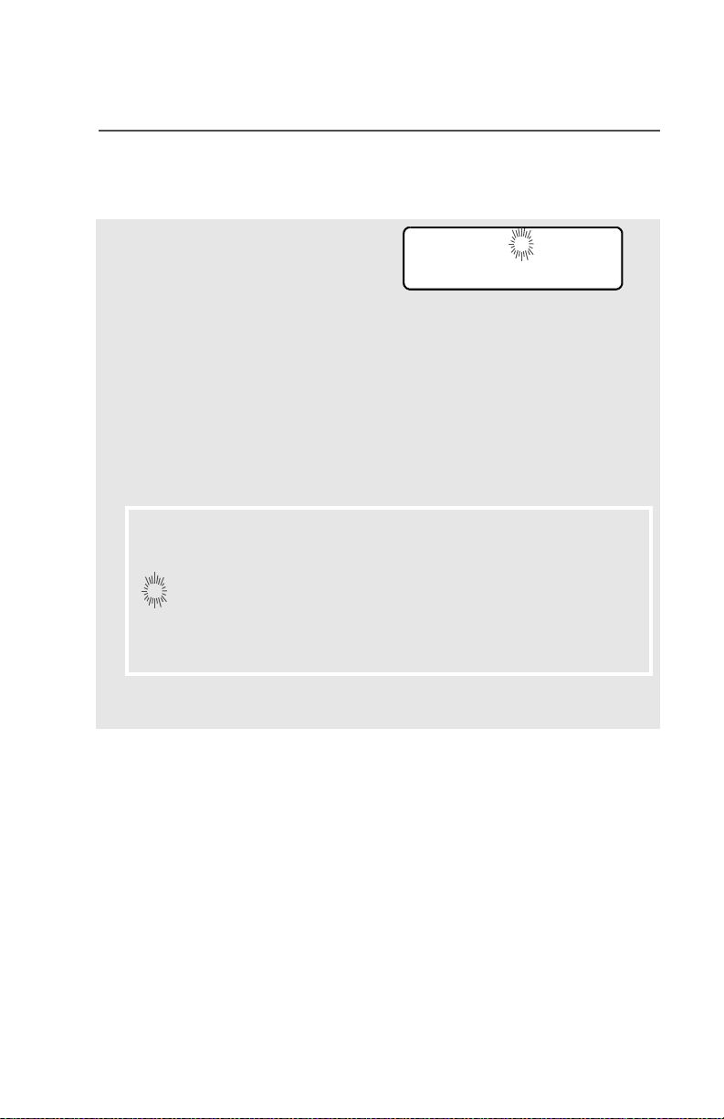
Edit a Call, Page, or Phone List Number
Use the Menu
1 Press U to find PROG.
PROG
2 Press D, E, or F
directly below PROG. You see
the lists that can be changed.
3 Press D, E, or F
directly below the name of the
list you wish to change. You
see the first list member. p
(blinking) indicates the
programming mode.
4 Press V or U to select
the list member to be
changed.
OR
You can use the keypad to
enter the corresponding
location number of the name
in the list.
5 Press D, E, or F
directly below NUM. The
blinking cursor shows the
location of the number to be
added.
CALL
PAGE PHON
FIRE CHIEF p
701234
NUM NAME
SECURITY p
704321
NUM NAME
SECURITY p
70432_
SAVE
6 Press V to erase digits. (If
you erase the entire number
and then press V or U,
you exit editing without saving
your changes.) Press a
keypad button to add a digit
(see “Keypad” on page 9).
ASTRO XTS 5000 Model III 41
SECURITY p
704321_
SAVE
Page 52
Common Radio Features
7 Press D, E, or F
directly below SAVE to save
your change. Return to step 4
to make more changes.
OR
Press h to return to the home
display.
Edit a Call, Page, or Phone List Name
Use the Menu
1 Press U to find PROG.
PROG
2 Press D, E, or F
directly below PROG. You see
the lists that can be changed.
3 Press D, E, or F
directly below the name of the
list you wish to change. You
see the first list member. p
(blinking) indicates the
programming mode.
4 Press V or U to select
the list member to be
changed.
OR
You can use the keypad to
enter the corresponding
location number of the name
in the list.
CALL
PAGE PHON
FIRE CHIEF p
701234
NUM NAME
SECURITY p
704321
NUM NAME
42
Page 53

Common Radio Features
5 Press D, E, or F
directly below NAME. The
blinking cursor shows the
location of the character to be
added.
6 Press V to erase
characters. (If you erase the
entire name and press V or
U, you exit editing without
saving your changes.) Press
a keypad button to add a
character (see “Keypad” on
page 9).
7 Press D, E, or F
directly below SAVE to save
your change. Return to step 4
to make more changes.
OR
Press h to return to the home
display.
GUARD_ p
704444
SAVE
_ p
704444
SAVE
Edit a Scan List
This feature lets you change scan list members and priorities.
Use the Menu
1 Press U to find PROG.
2 Press D, E, or F
directly below PROG. You see
the lists that can be changed.
3 Press U to find SCAN.
ASTRO XTS 5000 Model III 43
PROG
CALL
PAGE PHON
SCAN
Page 54

Common Radio Features
4 Press D, E, or F
directly below SCAN. You see
the first list member.
p (blinking) indicates the
programming mode.
5 Press V or U to find the
member you want to change.
6 Press D, E, or F
directly below SEL or DEL or
RCL.
SEL = add and/or change the priority of the currently displayed
channel in the scan list.
DEL = delete the currently displayed channel from the scan list.
RCL = view the next member of the scan list.
Note: The maximum number of members for a trunking priority
monitor scan list is 15; for a conventional scan list, 15; and
for a talkgroup scan list, 10.
7 To change the priority of the
currently displayed channel,
press D, E, or F
below SEL additional times to
see
T or S or S or no icon.
FIRE DISP NW p
SEL DEL RCL
SEL DEL RCL
T or S or S or no icon
T = this channel is in the scan list as a non-priority channel.
S = this channel is in the scan list as the priority 2 channel.
S (dot blinking) = this channel is in the scan list as the priority 1
channel. You will hear all traffic on the priority 1 channel,
regardless of traffic on non-priority channels.
no icon = this channel is deleted from the scan list.
Note: You cannot delete a priority channel from a scan list. In a
talkgroup scan list, priority cannot be assigned.
44
Page 55
Common Radio Features
8 Press V or U to select
more channels to be added or
deleted.
OR
Use the keypad to go directly
to additional channels to be
added or deleted.
OR
Use the 16-Position Select
knob to select additional
channels to be added or
deleted.
9 Press h to exit scan list
programming and return to
the home display.
Use the Menu and the Preprogrammed Select (Top Side) Button
1 Press U to find PROG.
PROG
2 Press D, E, or F
directly below PROG. You see
PAGE PHON
CALL
the lists that can be changed.
3 Press U to find SCAN.
4 Press D, E, or F
SCAN
FIRE DISP NW p
directly below SCAN. You see
the first list member.
p (blinking) indicates the
programming mode.
5 Press V or U to find the
member you want to change.
ASTRO XTS 5000 Model III 45
Page 56

Common Radio Features
6 Press the Select button once
to add the currently displayed
channel to the scan list.
AND/OR
Press the Select button one
or more times to change the
scan list status symbol of the
currently displayed channel.
Note: The maximum number of members for a trunking priority
monitor scan list is 15; for a conventional scan list, 15; and
for a talkgroup scan list, 10.
T or S or S or no icon
T = this channel is in the scan list as a non-priority channel.
S = this channel is in the scan list as the priority 2 channel.
S (dot blinking) = this channel is in the scan list as the priority 1
channel. You will hear all traffic on the priority 1 channel,
regardless of traffic on non-priority channels.
no icon = this channel is deleted from the scan list.
Note: You cannot delete a priority channel from a scan list. In a
talkgroup scan list, priority cannot be assigned.
7 Press V or U to select
more scan list members
whose scan status you want
to change.
OR
Use the keypad to go directly
to that scan list member.
OR
Use the 16-Position Select
knob to select another scan
list member.
46
Page 57

Common Radio Features
8 Press h to exit scan list
programming and return to
the home display.
Use the Preprogrammed Scan List Programming Switch and the
Menu
1 Move the Scan List
Programming switch to the
Programming position. You
see the first list member. p
(blinking) indicates the
programming mode.
2 Press V or U to find the
member you want to change.
FIRE DISP NW p
SEL DEL RCL
3 Press D, E, or F
directly below SEL or DEL or
RCL.
SEL = add and/or change the priority of the currently displayed
channel in the scan list.
DEL = delete the currently displayed channel from the scan list.
RCL = view the next member of the scan list.
Note: The maximum number of members for a trunking priority
monitor scan list is 15; for a conventional scan list, 15; and
for a talkgroup scan list, 10.
4 To change the priority of the
currently displayed channel,
press D, E, or F
below SEL additional times to
see
T or S or S or no icon.
SEL DEL RCL
T or S or S or no icon
ASTRO XTS 5000 Model III 47
Page 58

Common Radio Features
T = this channel is in the scan list as a non-priority channel.
S = this channel is in the scan list as the priority 2 channel.
S (dot blinking) = this channel is in the scan list as the priority 1
channel. You will hear all traffic on the priority 1 channel,
regardless of traffic on non-priority channels.
no icon = this channel is deleted from the scan list.
Note: You cannot delete a priority channel from a scan list. In a
talkgroup scan list, priority cannot be assigned.
5 Press V or U to select
more channels to be added or
deleted.
OR
Use the keypad to go directly
to additional channels to be
added or deleted.
OR
Use the 16-Position Select
knob to select additional
channels to be added or
deleted.
6 Move the Scan List
Programming switch out of
the Programming position.
Change the Scan List Status Only
1 Move the Scan List
Programming switch to the
Programming position. You
see the first list member.
p (blinking) indicates the
programming mode.
48
FIRE DISP NW p
Page 59
2 Press V or U to find the
member you want to change.
Common Radio Features
3 Press the Select button once
to add the currently displayed
channel to the scan list.
AND/OR
Press the Select button one
or more times to change the
scan list status symbol of the
currently displayed channel.
Note: The maximum number of members for a trunking priority
monitor scan list is 15; for a conventional scan list, 15; and
for a talkgroup scan list, 10.
T or S or S or no icon
T = this channel is in the scan list as a non-priority channel.
S = this channel is in the scan list as the priority 2 channel.
S (dot blinking) = this channel is in the scan list as the priority 1
channel. You will hear all traffic on the priority 1 channel,
regardless of traffic on non-priority channels.
no icon = this channel is deleted from the scan list.
Note: You cannot delete a priority channel from a scan list. In a
talkgroup scan list, priority cannot be assigned.
4 Press V or U to select
more list members whose
scan status you want to
change.
OR
You can use the keypad to go
directly to that scan list member.
OR
ASTRO XTS 5000 Model III 49
Page 60

Common Radio Features
You can use the 16-Position
Select knob to select another
scan list member.
5 Move the Scan List
Programming switch out of
the Programming position.
50
Page 61

Common Radio Features
Scan
The scan feature allows you to monitor traffic on different channels by
scanning a preprogrammed list of channels. Your radio can have up
to 32 different scan lists. These lists must be preprogrammed by a
qualified radio technician.
• To view your radio’s scan lists, see “View a List” on page 40.
• To change your radio’s scan lists, see “Edit a Scan List” on
page 43.
Turn Scan On or Off
Use the Menu
1 Press U to find SCAN.
SCAN
2 Press D, E, or F
directly below SCAN. You see
the current scan state.
The scan status symbol is
displayed when scan is on.
3 Press D, E, or F
directly below ON or OFF.
OR
You can press h or the PTT
button to exit scan and return
to the home display without
changing the scan state.
Use the Preprogrammed Scan On/Off Switch
Place the Scan switch in the
Scan On or Scan Off posi-
tion. The scan status symbol
is displayed when scan is on.
SCAN ON T
ON OFF
OR
SCAN OFF
ON OFF
SCAN
T
ASTRO XTS 5000 Model III 51
Page 62

Common Radio Features
Delete a Nuisance Channel
When the radio scans to a channel that you do not wish to hear
(nuisance channel), you can temporarily delete the channel from the
scan list.
1 When the radio is locked
onto the channel to be
deleted, press the
preprogrammed Nuisance
Delete button.
Repeat this step to delete
more channels.
Note: You cannot delete priority
channels or the
designated transmit
channel.
2 The radio continues scanning
the remaining channels in the
list. To resume scanning the
deleted channel, change
channels or turn scan off and
then back on again.
52
Page 63

Common Radio Features
Conventional Scan Only
Make a Dynamic Priority Change
While the radio is scanning, the dynamic priority change feature lets
you temporarily change any channel in a scan list (except the priorityone channel) to the priority-two channel. The replaced priority-two
channel becomes a non-priority channel. This change remains in
effect until scan is turned off, then scanning reverts back to the
preprogrammed state.
1 When the radio is locked
onto the channel to be
designated as priority-two,
press the preprogrammed
Dynamic Priority button.
Note: The priority-one
channel cannot be
changed to prioritytwo.
2 The radio continues scanning
the remaining channels in the
list. To resume scanning the
preprogrammed priority-two
channel, you must leave and
re-enter scan operation.
ASTRO XTS 5000 Model III 53
Page 64

Common Radio Features
Telephone Calls (Trunking Only)
Use your radio to make calls similar to standard phone calls. A
landline phone can be used to call a radio, or a radio can be used to
call a landline phone.
Quick Access (One-Touch)
If your radio is preprogrammed for Quick Access (One-Touch) Phone
Call, you can make a call to one preprogrammed phone number
without having to select the feature or a phone number.
1 Press the Quick Access
Phone button to dial the
phone number.
2 If your call is answered, press
the PTT button to talk;
release the PTT to listen.
OR
If your call is not answered,
go to “Phone Call Display
and Alert Prompts” on
page 57.
3 When your call is completed,
press h to hang up. The radio
returns to the home display.
54
Page 65

Common Radio Features
Answer a Phone Call
Use the preprogrammed Call Response button to answer a call.
1 When a phone call is
received, you hear a
telephone-type ringing, the
LED blinks GREEN, the call
received symbol (
and PHONE CALL is displayed.
2 Press the Call Response
button within 20 seconds after
the call indicators begin.
3 Press and hold the PTT
button to talk; release it to
listen.
4 Press h to hang up and return
to the home display.
m) blinks,
Initiate a Phone Call
1 Press U to find PHON.
2 Press D, E, or F
directly below PHON. You see
the last transmitted phone
number.
• Telephone-type ringing
• Blinking GREEN LED
PHONE CALL m
PHON
5551234
LIST
3 Go to “Select a Phone
Number” on page 56.
OR
Go to “Make a Phone Call”
on page 56.
ASTRO XTS 5000 Model III 55
•Use the Menu
• Use the Keypad
Page 66

Common Radio Features
Select a Phone Number
Use the Menu
1 Press U to find the phone
number you want.
Note: Press LNUM to go to the
last number dialed.
2 Go to “Make a Phone Call”,
below.
Use the Keypad
1 Use the keypad to enter the
phone number you want.
Note: Press LNUM to go to the
last number dialed.
2 Go to “Make a Phone Call”,
below.
POLICE
5558523
LNUM
POLICE
5558523
LNUM
Make a Phone Call
1 Press and release the PTT
button to dial the phone
number.
2 If your call is answered, press
the PTT button to talk;
release the PTT to listen.
OR
If your call is not answered,
go to “Phone Call Display
and Alert Prompts” on
page 57.
3 When your call is completed,
press h to hang up. The radio
returns to the home display.
56
Page 67
Common Radio Features
Table 8: Phone Call Display and Alert Prompts
When you press the PTT button
NO PHONE
and the phone system is not
available, you hear a long tone.
•A long tone
Press h to hang up. The radio
returns to the home display.
When a channel is not available,
PHONE BUSY
you hear a busy tone.
The radio automatically connects
• A busy tone
when a channel opens.
When the phone system is busy,
PHONE BUSY
you hear a long tone.
Press h to exit the phone mode
•A long tone
and try your call later.
The call is not acknowledged.
NO ACKNOWLDG
Press h to hang up. The radio
returns to the home display.
Notes: • A high-pitched tone, generated when you release the PTT
button, indicates to the landline party that he or she may
begin talking.
• You have the option of sending additional digits (overdial),
such as an extension number, or credit card or PIN
numbers, to the phone system. If the radio is programmed
for live overdial, every digit entered after the call is
connected is sent to the phone system.
• If the radio is programmed for buffered overdial, the digits
pressed are entered into memory and then sent when the
PTT button is pressed. Press the PTT to send either digits
or voice, but not both at the same time.
ASTRO XTS 5000 Model III 57
Page 68

Common Radio Features
Private Calls (Trunking Only)
These one-to-one calls between two radios are not heard by others in
the current talkgroup. The calling radio automatically verifies that the
receiving radio is active on the system and can display the caller’s ID.
Quick Access (One-Touch)
If your radio is preprogrammed for Quick Access (One-Touch) Private
Call, you can make a call to one preprogrammed ID number without
having to select the feature or an ID number.
1 Press the Quick Access
Private Call button to start
the Private Call.
The called ID is momentarily
displayed, then you see
PLEASE WAIT.
2 When you are connected, you
see the called ID. Press and
hold the PTT button to talk;
release the PTT to listen.
OR
If no acknowledgment is
received, you see NO
ACKNOWLDG.
OR
If the target radio does not
respond before the time out,
you see NO ANSWER.
3 Press h to hang up and return
to the home display.
FIRE CHIEF
ID: 701234
PLEASE WAIT
FIRE CHIEF
ID: 701234
NO ACKNOWLDG
NO ANSWER
58
Page 69

Common Radio Features
Answer a Private Call
Use the preprogrammed Call Response button to answer a call.
1 When a Private Call is
received, you hear two alert
tones, the LED blinks
GREEN, the call received
symbol (
RECEIVD is displayed.
2 Press the Call Response
button within 20 seconds.
If the caller’s name is in the
call list, it will be displayed
during the call.
OR
If the caller’s name is not in
the call list, the caller’s ID
number is displayed.
3 Press and hold the PTT
button to talk; release it to
listen.
4 Press h or the Call
Response button to hang up
and return to the home
display.
m) blinks, and CALL
•Two tones
• Blinking GREEN LED
CALL RECEIVD m
Initiate a Private Call
1 Press U to find CALL.
2 Press D, E, or F
directly below CALL. You see
the last transmitted or
received ID number.
ASTRO XTS 5000 Model III 59
CALL
ID: 702345
LIST
Page 70
Common Radio Features
3 Go to “Select an ID Number”,
below.
OR
Go to “Make a Private Call”
on page 61.
Select an ID Number
Use the Menu
1 Press U to find the ID
number you want.
Note: Press LNUM to go to the
last number dialed.
2 Go to “Make a Private Call”
on page 61.
Use the Keypad
1 Use the keypad to enter the
ID number you want.
Note: Press LNUM to go to the
last number dialed.
• Use the Menu
• Use the Keypad
FIRE CHIEF
ID: 701234
LNUM
FIRE CHIEF
ID: 701234
LNUM
2 Go to “Make a Private Call”
on page 61.
60
Page 71

Make a Private Call
1 Press the PTT button to start
the Private Call.
Common Radio Features
The called ID is momentarily
displayed, then you see
PLEASE WAIT.
2 When you are connected, you
see the called ID. Press and
hold the PTT button to talk;
release the PTT to listen.
OR
If no acknowledgment is
received, you see NO
ACKNOWLDG.
OR
If the target radio does not
respond before the time out,
you see NO ANSWER.
3 When your call is completed,
press h to hang up. The radio
returns to the home display.
FIRE CHIEF
ID: 701234
PLEASE WAIT
FIRE CHIEF
ID: 701234
NO ACKNOWLDG
NO ANSWER
ASTRO XTS 5000 Model III 61
Page 72

Common Radio Features
Selective Calls (ASTRO Conventional Only)
A Selective Call is used to call a select individual. It is intended to
provide privacy and to eliminate the annoyance of having to listen to
conversations that are of no interest to you.
Quick Access (One-Touch)
If your radio is preprogrammed for Quick Access (One-Touch)
Selective Call, you can make a call to one preprogrammed ID number
without having to select the feature or an ID number.
1 Press the Quick Access
Selective Call button to start
the Selective Call.
2 When you are connected, you
see the called ID. Press and
hold the PTT button to talk;
release the PTT to listen.
3 Press h to hang up and return
to the home display.
Answer a Selective Call
1 When a Selective Call is
received, you hear two alert
tones, the LED blinks
GREEN, the call received
symbol (
RECEIVD is displayed.
2 The display will remain active
for two seconds, and then
the speaker will unmute.
3 Press and hold the PTT
button to talk; release it to
listen.
m) blinks, and CALL
FIRE CHIEF
ID: 701234
•Two tones
• Blinking GREEN LED
CALL RECEIVD m
62
Page 73

4 Press h to hang up and return
to the home display.
Initiate a Selective Call
Common Radio Features
1 Press U to find CALL.
2 Press D, E, or F
directly below CALL. You see
the last transmitted or
received ID number.
3 Go to “Select an ID Number”,
below.
OR
Go to “Make a Selective Call”
on page 64.
Select an ID Number
Use the Menu
1 Press U to find the ID
number you want.
Note: Press LNUM to go to the
last number dialed.
2 Go to “Make a Selective Call”
on page 64.
CALL
ID: 702345
LIST
•Use the Menu
• Use the Keypad
FIRE CHIEF
ID: 701234
LNUM
ASTRO XTS 5000 Model III 63
Page 74

Common Radio Features
Use the Keypad
1 Use the keypad to enter the
ID number you want.
Note: Press LNUM to go to the
last number dialed.
2 Go to “Make a Selective
Call”, below.
Make a Selective Call
1 Press the PTT button to start
the Selective Call.
FIRE CHIEF
ID: 701234
LNUM
2 When you are connected, you
see the called ID. Press and
hold the PTT button to talk;
release the PTT to listen.
3 When your call is completed,
press h to hang up. The radio
returns to the home display.
FIRE CHIEF
ID: 701234
64
Page 75

Common Radio Features
Call Alert Paging
Call Alert allows your radio to work like a pager. Even if other users
are away from their radios, or if they are unable to hear their radios,
you can still send them a Call Alert page. You can also verify if a radio
is active on the system.
In conventional operation, you can send either an individual Call Alert
page or a group Call Alert page. ID numbers for individuals are
preceded by ID: and for groups by GR:.
Quick Access (One-Touch)
If your radio is preprogrammed for Quick Access (One-Touch) Call
Alert Paging, you can send a page to one preprogrammed ID number
without having to select the feature or an ID number.
1 Press the Quick Access
Call Alert button to send the
Call Alert. You see PLEASE
WAIT.
2 When you are connected, you
see the home display. Press
and hold the PTT
button to talk; release the
PTT to listen.
OR
If an individual Call Alert
page is not acknowledged,
you see NO ACKNOWLDG.
If a group Call Alert page is
not acknowledged, you do
not see NO ACKNOWLDG. The
radio will merely exit Call
Alert and return to normal
operation.
PLEASE WAIT
NO ACKNOWLDG
ASTRO XTS 5000 Model III 65
Page 76

Common Radio Features
3 Press h or the Call
Response button to hang up
and return to the home
display.
Answer a Call Alert Page
1 When a Call Alert page is
received, you hear four
repeating alert tones, the
LED blinks GREEN, the call
received symbol (
and PAGE RECEIVD is
displayed.
2 Press and hold the PTT
button to talk; release it to
listen.
m) blinks,
• Four repeating alert tones
• Blinking GREEN LED
=
PAGE RECEIVD m
66
Page 77

Initiate a Call Alert Page
Common Radio Features
1 Press U to find PAGE.
2 Press D, E, or F
directly below PAGE.
If an individual Call Alert
page was last transmitted or
received, you see the
individual ID number.
If a group Call Alert page
was last transmitted, you see
blanks in the individual ID
scratchpad and the group ID
transmitted to in the group ID
scratchpad (accessed by
pressing V once).
If a group Call Alert page
was last received, you see
the ID of the sending radio in
the individual ID scratchpad
and the group ID transmitted
to in the group ID
scratchpad.
PAGE
FIRE CHIEF
ID: 701234
LIST
FIRE CHIEF
ID: ______
LIST
FIRE DEPT
GR: 704440
LIST
3 Go to “Select an ID Number”
on page 68.
OR
Go to “Send a Call Alert
Page” on page 68.
ASTRO XTS 5000 Model III 67
•Use the Menu
• Use the Keypad
Page 78

Common Radio Features
Select an ID Number
Use the Menu
1 Press U to find the ID
number you want.
Note: Press LNUM to go to the
last number dialed.
2 Go to “Send a Call Alert
Page”, below.
Use the Keypad
1 Use the keypad to enter the
ID number you want.
Note: Press LNUM to go to the
last number dialed.
2 Go to “Send a Call Alert
Page”, below.
FIRE CHIEF
ID: 701234
LNUM
FIRE CHIEF
ID: 701234
LNUM
Send a Call Alert Page
1 Press the PTT button to send
the Call Alert to the displayed
number. You see PLEASE
WAIT.
2 When you are connected, you
see the home display. Press
and hold the PTT
button to talk; release the
PTT to listen.
OR
68
PLEASE WAIT
Page 79

Common Radio Features
If an individual Call Alert
page is not acknowledged,
you see NO ACKNOWLDG.
If a group Call Alert page is
not acknowledged, you do
not see NO ACKNOWLDG. The
radio will merely exit Call
Alert and return to normal
operation.
3 Press h to hang up and return
to the home display.
NO ACKNOWLDG
ASTRO XTS 5000 Model III 69
Page 80

Common Radio Features
Conventional Talkgroup Calls (Conventional
Operation Only)
Talkgroup Call lets you define a group of conventional system users
so that they can share the use of a conventional channel.
Encryption keys are slaved to talkgroups. When talkgroups are
enabled, encryption keys are changed by changing the active
talkgroup. See “Secure Operations” on page 77.
Select a Talkgroup
1 Press U to find TGRP.
2 Press D, E, or F
directly below TGRP. You see
the last talkgroup that was
selected and stored, and SEL
and PSET.
3 Press V or U to find the
talkgroup you want.
OR
Use the keypad to enter the
number of the corresponding
talkgroup in the list.
4 Press D, E, or F
directly below SEL or PSET.
SEL (SELECT) — Saves the currently displayed talkgroup and
returns to the home display.
PSET (PRESET) — Selects the preset preprogrammed talkgroup.
If the encryption key slaved
to the new talkgroup is
erased, you see KEY FAIL
and hear a momentary key
fail tone.
TGRP
SEL PSET
SEL PSET
KEY FAIL
• Momentary key fail tone
70
Page 81

Common Radio Features
If the encryption key that is
slaved to the new talkgroup
is not allowed, you see ILLE
GAL KEY and hear a momentary key fail tone.
5 Press h or the PTT button, or
turn the 16-Position Select
knob to exit.
ILLEGAL KEY
• Momentary key fail tone
ASTRO XTS 5000 Model III 71
Page 82

Common Radio Features
Status Calls (ASTRO 25 Trunking Only)
You can send data calls to the dispatcher about a predefined status.
Each status can have up to a 12-character name. A maximum of eight
status conditions is possible.
Send a Status Call
Use the Menu
1 Press U to find STS.
2 Press D, E, or F
directly below STS. The last
acknowledged status call, or
the first status in the list, is
displayed.
3 Press V or U to find the
status you wish to send.
OR
Use the keypad to enter a
number corresponding to the
location in the status list.
STS
4 Press the PTT button to send
the status.
When the dispatcher
acknowledges, four tones
sound, ACK RECEIVED is dis-
played, and the radio returns
to normal dispatch operation.
OR
If no acknowledgment is
received, you will see NO
ACKNOWLDG and hear a lowpitched tone.
5 Press h to go to the home
display
72
ACK RECEIVED
• Four tones
NO ACKNOWLDG
• Single tone
Page 83

Common Radio Features
Note: No traffic is heard on trunked channels while Status Calls is
selected.
If the radio detects no Status Call activity for six seconds, an
alert tone sounds until h or the PTT button is pressed.
Use the Preprogrammed Status Button
1 Press the Status button. The
last acknowledged status
call, or the first status in the
list, is displayed.
2 Press V or U to find the
status you wish to send.
OR
Use the keypad to enter a
number corresponding to the
location in the status list.
3 Press the PTT button to send
the status.
When the dispatcher
ACK RECEIVED
acknowledges, four tones
sound, ACK RECEIVED is dis-
played, and the radio returns
• Four tones
to normal dispatch operation.
OR
If no acknowledgment is
NO ACKNOWLDG
received, you will see NO
ACKNOWLDG and hear a low-
pitched tone.
• Single tone
4 Press h to go to the home
display
Note: No traffic is heard on trunked channels while Status Calls is
selected.
If the radio detects no Status Call activity for six seconds, an
alert tone sounds until the PTT button is pressed.
ASTRO XTS 5000 Model III 73
Page 84

Common Radio Features
Repeater or Direct Operation
Also known as “talkaround operation,” DIRECT lets you bypass the
repeater and connect directly to another radio. The transmit and
receive frequencies are the same.
REPEATER operation increases radio’s range by connecting with
other radios through a repeater. The transmit and receive frequencies
are different.
Select Repeater or Direct Operation
Use the Menu
1 Press U to find DIR.
2 Press D, E, or F
directly below DIR. You
momentarily see the current
operation.
DIR
• For Direct mode
• For Repeater mode
3 Press D, E, or F
directly below DIR or RPTR.
If DIR is selected, the display
shows
OR
Press h to exit without
changing the current
operation.
r and DIRECT MODE.
74
DIRECT MODE
DIR RPTR
OR
RPTR MODE
DIR RPTR
r
DIRECT MODE
Page 85

Common Radio Features
Use the Preprogrammed Repeater/Direct Switch
Place the Repeater/Direct
switch in either the Repeater
or the Direct position. If DIR
is selected, the display
shows
r.
r
ASTRO XTS 5000 Model III 75
Page 86

Common Radio Features
Smart PTT (Conventional Only)
Smart PTT is a per-channel, programmable feature used in
conventional radio systems to keep radio users from talking over
other radio conversations.
When smart PTT is enabled in your radio, you will not be able to
transmit on an active channel. If you try to transmit on an active
smart-PTT channel, you will hear an alert tone, and the transmission
will be inhibited. The LED will also blink red to indicate that the
channel is busy.
Three radio-wide variations of smart PTT are available:
Transmit Inhibit on
Busy Channel with
Carrier
Transmit Inhibit on
Busy Channel with
Wrong Squelch Code
Quick-Key Override This feature can work in conjunction with
You cannot transmit if any traffic is
detected on the channel.
You cannot transmit on an active channel
with a squelch code or (if secureequipped) encryption key other than your
own. If the PL code is the same as yours,
the transmission will not be prevented.
either of the two above variations. You
can override the transmit-inhibit state by
quick-keying the radio. In other words,
two PTT Button presses within the
preprogrammed time limit.
76
Page 87

Special Radio Features
Secure Operations
Secure radio operation provides the highest commercially available
level of voice security on both trunked and conventional channels.
Unlike other forms of security, Motorola digital encryption provides
signaling that makes it virtually impossible for others to decode any
part of an encrypted message.
Note: Secure operation is not available in trunked analog modes.
Select Secure Transmissions
Turn the preprogrammed
Secure/Clear switch to the
secure position (D).
Note: If the selected channel
is programmed for clearonly operation — when
you press the PTT
button, you see CLR TX
ONLY, and you hear an
invalid mode tone.
The radio will not transmit until you set the Secure/
Clear switch to the clear position (E).
c
CLR TX ONLY
• Invalid mode tone
Select Clear Transmissions
Turn the preprogrammed Secure/Clear switch to the clear
position (E).
Note: If the selected channel
is programmed for
secure-only operation —
when you press the PTT
button, you see SEC TX
ONLY, and you hear an
invalid mode tone.
SEC TX ONLY
• Invalid mode tone
The radio will not transmit until you set the Secure/
Clear switch to the secure position (D).
ASTRO XTS 5000 Model III 77
Page 88

Special Radio Features
Managing Encryption
Key Loading
Refer to the key-variable loader (KVL) manual for equipment
connections and setup.
1 Attach the KVL to your radio.
When it is attached, the
display will show
KEYLOADING, and all other
radio functions, except for
power down, backlight, and
volume, will be locked out.
2 Press the PTT button on the
KVL. This will load the
encryption keys into your
radio. When the key has
been loaded successfully,
the radio will sound a short
tone for single-key radios; for
multikey radios, an
alternating tone will be
heard.
Multikey
The multikey feature allows your radio to be equipped with as many
as 48 different encryption keys and supports the DES-OFB algorithm.
• Conventional Multikey — The encryption keys can be tied
(strapped), on a one-per-channel basis, through radio service
software. In addition, you can have operator-selectable keys,
operator-selectable keysets, and operator-selectable key erasure.
If talkgroups are enabled in conventional, then the encryption keys
are strapped to the talkgroups.
• Trunked Multikey — If you use your radio for both conventional
and trunked applications, you will have to strap your encryption
keys for trunking on a per-talkgroup or announcement-group
basis. In addition, you may strap a different key to other features,
KEYLOADING
78
Page 89

Special Radio Features
such as dynamic regrouping, failsoft, or emergency talkgroup. You
can have operator-selectable key erasure.
Key Selection
1 Press U until KEY appears
KEY
on the display.
2 Press D, E, or F
directly below KEY. The
display changes to show the
HW KEY 1
PSET
SEL ABRT
last user-selected and stored
encryption key and the
available menu selections.
3 Press V or U to scroll
through the encryption keys.
OR
Enter the number of the
desired key using the
keypad.
Note: If an erased key is selected, the key name will be
alternated with ERASED KEY.
4 Press D, E, or F
directly below the desired
menu selection.
OR
If you selected the key via
the keypad, press V or
U to scroll through the
menu selections:
PSET or PRESET = selects the preset or default encryption key.
SEL = saves the newly selected key and returns to the home
display.
ASTRO XTS 5000 Model III 79
Page 90

Special Radio Features
5 Press h, the PTT button, the
ABRT menu selection, or turn
the 16-Position Select knob
to exit this menu.
Note: If the selected key is
erased, KEY FAIL will
be displayed and a
momentary keyfail
tone will be
generated.
If the selected key is
not allowed, ILLEGAL
KEY will be displayed
and a momentary
illegal key tone,
similar to the key fail
tone, will be
generated.
Keyset Selection
This feature allows you to select one or more groups of several
encryption keys from among the available keys stored in the radio.
For example, you could have a group of three keys structured to one
keyset, and another group of three different keys structured to
another keyset; by changing keysets, you would automatically switch
from one set of keys to the other. Every channel to which one of the
original keys was tied will now have the equivalent new key instead.
KEY FAIL
ILLEGAL KEY
1 Press U until KSET
appears on the display.
2 Press D, E, or F
directly below KSET. The
display changes to show the
last user-selected and stored
keyset and the available
keyset menu selections.
80
KSET
KEYSET 1
SEL
KS1 KS2
Page 91

Special Radio Features
3 Press D, E, or F
directly below the desired
keyset.
OR
Enter the number of the
desired keyset using the
keypad.
4 To save the newly selected
keyset, press the button
directly below SEL. The radio
will then exit keyset selection
and return to the home
display.
Note: Press h, the PTT button, the ABRT menu selection, or turn
the 16-Position Select knob to exit this menu at any time
without changing the keyset selection.
ASTRO XTS 5000 Model III 81
Page 92

Special Radio Features
Key Zeroization
This enables the user to erase all or selected encryption keys.
Use the Menu
1 Press U until the display
shows ERAS.
ERAS
2 Press D, E, or F
directly below ERAS. The
display shows the last userselected and stored
encryption key, and the
available menu selections:
ALL = erases all the encryption keys in the radio. The
display shows ERS ALL
KEYS and YES and NO.
SNGL = selects the displayed
encryption key to be erased.
The display shows ERS SNGL
KEY and YES and NO.
ABRT = exits this menu and
returns to the home display.
Note: Press h, the PTT button, the ABRT menu selection, or turn
the 16-Position Select knob to exit this menu at any time
without erasing any keys.
SNGL ABRT
YES NO
YES NO
ALL
ERS ALL KEYS
ERS SNGL KEY
82
Page 93

3 Press D, E, or F
directly below the desired
menu selection.
OR
Press V or U to find the
desired encryption key. The
display shows the selected
key, and the available menu
selections shown in step 2.
Press D, E, or F
directly below the desired
menu selection.
OR
Enter the location number of
the desired key, using the
keypad. The display shows
the selected key, and the
available menu selections
shown in step 2. Press D,
E, or F directly below
the desired menu selection.
Special Radio Features
4 Press h, the PTT button, the
ABRT menu selection, or turn
the 16-Position Select knob
to exit this menu.
ASTRO XTS 5000 Model III 83
Page 94
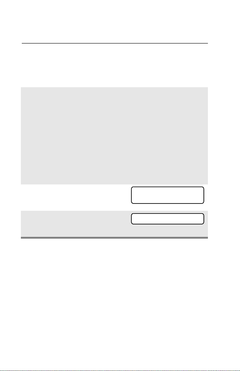
Special Radio Features
Use the Buttons
Note: This is the method used for erasing the single key in radios
with the single-key option, and for erasing all keys in radios
with the multikey option.
1 With the radio on, press and
hold the Top Side button;
while holding this button
down, press the Top button.
Note: DO NOT press the
Top button before
pressing the Top Side
button, unless you are
in an emergency
situation; this would
send an emergency
alarm.
2 Before the keys are erased,
the display shows PLEASE
WAIT.
3 When all the encryption keys
have been erased, the
display shows ERASED.
84
PLEASE WAIT
ERASED
Page 95

Special Radio Features
Over-the-Air Rekeying (Rekey Request) (ASTRO Conventional
Only)
The over-the-air rekeying (OTAR) feature allows the dispatcher to
reprogram the encryption keys in the radio remotely. The dispatcher
performs the rekey operation upon receiving a rekey request from the
user.
Use the Menu
1 Press U to find REKY.
2 Press D, E, or F directly
REKY
REQUEST REKY
below REKY.
3 Press the PTT to send the
PLEASE WAIT
rekey request.
Note: Pressing the PTT again, or the Home or Emergency
button, will exit the feature and allow the user to
transmit in the normal manner.
4 If the display shows REKEY
REKEY FAIL
FAIL and a bad-key tone
sounds, the rekey operation has
failed.
Note: If this occurs, your radio does not contain the Unique
Shadow Key (USK). This key must be loaded into the
radio with the key-variable loader (KVL) before the
rekey request can be sent. Refer to your local key
management supervisor for more information.
ASTRO XTS 5000 Model III 85
Page 96

Special Radio Features
Digital PTT ID
Receive
This feature allows you to see the radio ID number of the radio you
are currently receiving. This ID can be a maximum of eight characters
and can be viewed by both the receiving radio and the dispatcher.
Transmit
Your radio’s ID number is automatically sent every time the PTT
button is pressed. This is a per-channel feature. For digital voice
transmissions, your radio’s ID is sent continuously during the voice
message.
86
Page 97

View Your Radio’s ID Number
Use the Menu
Special Radio Features
1 Press U to find CALL or
PAGE.
2 Press D, E, or F directly
below CALL or PAGE.
3 Press V.
Use the Preprogrammed Call or Page Button
1 Press the Call or Page button.
2 Press V.
CALL PAGE
MY ID:
701111
MY ID:
701111
ASTRO XTS 5000 Model III 87
Page 98

Special Radio Features
Dynamic Regrouping (Trunking Only)
The dynamic regrouping feature lets the dispatcher temporarily
reassign selected radios to a single special channel so they can
communicate with each other. This feature is typically used during
special operations and is enabled by a qualified radio technician. You
will not notice whether your radio has this feature enabled until a
dynamic regrouping command is sent by the dispatcher.
Note: If you try to access a zone or channel that has been reserved
by the dispatcher as a dynamically regrouped mode for other
users, you will hear an invalid tone.
When your radio is dynamically regrouped, it automatically
switches to the dynamically regrouped channel. You see the
dynamically regrouped channel’s name, and hear a “gurgle”
tone.
Press the PTT button to talk; release it to listen.
When the dispatcher cancels dynamic regrouping, the radio
automatically returns to the zone and channel that you were
using before the radio was dynamically regrouped.
Reprogram Request (ASTRO 25 Trunking Only)
This feature lets you notify the dispatcher that you want a new
dynamic regrouping assignment.
Use the Menu
1 Press U to find RPGM.
2 Press D, E, or F directly
below RPGM.
The reprogram request is sent
to the dispatcher.
RPGM
REPRGRM RQST
88
Page 99

3 If you hear one beep
- Press the PTT button to send
the reprogram request again.
OR
-Press h to cancel and return
to the home display.
OR
If you hear five beeps, the
reprogram request was
acknowledged by the dispatcher. Your radio returns to
the home display.
OR
Special Radio Features
If the dispatcher does not
NO ACKNOWLDG
acknowledge the reprogram
request within six seconds, you
see NO ACKNOWLDG and hear a
• An alert tone
low-pitched alert tone.
Try again or press h.
Use the Preprogrammed Reprogram Request Button
1 Press the Reprogram
REPRGRM RQST
Request button. You see
REPRGRM RQST.
The reprogram request is sent
to the dispatcher.
ASTRO XTS 5000 Model III 89
Page 100

Special Radio Features
2 If you hear one beep
- Press the PTT button to send
the reprogram request again
OR
- Press h to hang up and
return to the home display.
OR
If you hear five beeps, the
reprogram request was
acknowledged by the dispatcher. Your radio returns to
the home display.
OR
If the dispatcher does not
acknowledge the reprogram
request within six seconds, you
see NO ACKNOWLDG and hear a
low-pitched alert tone.
Try again or press h.
• One beep
• Five beeps
NO ACKNOWLDG
• An alert tone
Select Enable / Disable
The dispatcher can classify regrouped radios into either of two
categories: Select Enabled or Select Disabled.
• Select-enabled radios are free to change to any available channel,
including the dynamic-regrouping channel, once the user has
selected the dynamic-regrouping position.
• Select-disabled radios cannot change channels while dynamically
regrouped. The dispatcher has forced the radio to remain on the
dynamic-regrouping channel.
The Scan or Private Call feature cannot be selected while your radio
is Select Disabled.
90
 Loading...