

Page 1

®
ASTRO
TM
XTS
Portable Radio
Basic Service Manual
4000
Page 2

Page 3

Title Page
ASTRO® XTS™ 4000
Digital Portable Radios
Basic Service Manual
Motorola, Inc.
1301 E. Algonquin Rd.
Schaumburg, IL 60196-1078 U.S.A.
6871619L01-C
Page 4

Foreword
This manual covers all models of the ASTRO® XTS™ 4000 digital portable radio, unless otherwise specified. It includes all
the information necessary to maintain peak product performance and maximum working time, using levels 1 and 2
maintenance procedures. This level of service goes down to the board replacement level and is typical of some local
service centers, self-maintained customers, and distributors.
For details on radio operation or component-level troubleshooting, refer to the applicable manuals available separately. A
list of related publications is provided in the section, “ Related Publications” on page ix.
Product Safety and RF Exposure Compliance
Before using this product, read the operating instructions for safe usage contained in the Product Safety and RF Exposure booklet enclosed with your radio.
ATTENTION!
This radio is restricted to occupational use only to satisfy FCC RF energy exposure requirements.
Before using this product, read the RF energy awareness information and operating instructions in the
Product Safety and RF Exposure booklet enclosed with your radio (Motorola Publication part number
6881095C98) to ensure compliance with RF energy exposure limits.
For a list of Motorola-approved antennas, batteries, and other accessories, visit the following web site which lists approved accessories: http://www.motorola.com/governmentandenterprise
Manual Revisions
Changes which occur after this manual is printed are described in FMRs (Florida Manual Revisions). These FMRs provide
complete replacement pages for all added, changed, and deleted items, including pertinent parts list data, schematics, and
component layout diagrams. To obtain FMRs, contact the nearest Radio Products and Solutions Organization (refer to
“Appendix B Replacement Parts Ordering”).
Computer Software Copyrights
The Motorola products described in this manual may include copyrighted Motorola computer programs stored in
semiconductor memories or other media. Laws in the United States and other countries preserve for Motorola certain
exclusive rights for copyrighted computer programs, including, but not limited to, the exclusive right to copy or reproduce in
any form the copyrighted computer program. Accordingly, any copyrighted Motorola computer programs contained in the
Motorola products described in this manual may not be copied, reproduced, modified, reverse-engineered, or distributed in
any manner without the express written permission of Motorola. Furthermore, the purchase of Motorola products shall not
be deemed to grant either directly or by implication, estoppel, or otherwise, any license under the copyrights, patents or
patent applications of Motorola, except for the normal non-exclusive license to use that arises by operation of law in the
sale of a product.
Document Copyrights
No duplication or distribution of this document or any portion thereof shall take place without the express written permission
of Motorola. No part of this manual may be reproduced, distributed, or transmitted in any form or by any means, electronic
or mechanical, for any purpose without the express written permission of Motorola.
Disclaimer
The information in this document is carefully examined, and is believed to be entirely reliable. However, no responsibility is
assumed for inaccuracies. Furthermore, Motorola reserves the right to make changes to any products herein to improve
readability, function, or design. Motorola does not assume any liability arising out of the applications or use of any product
or circuit described herein; nor does it cover any license under its patent rights nor the rights of others.
Trademarks
MOTOROLA, the Stylized M logo, ASTRO, FLASHport, and CommPort are registered in the US Patent & Trademark
Office. All other products or service names are the property of their respective owners.
© 2007–2008 by Motorola, Inc.
Page 5

Document History iii
Document History
The following major changes have been implemented in this manual since the previous edition:
Edition Description Date
6871619L01-A Initial edition Mar. 2007
6871619L01-B Added UHF band Jan. 2008
6871619L01-C Added PMNN4083 1260 mAh Li-Ion Battery.
Modified Specifications and Accessories info.
Sep. 2008
6871619L01-C September 10, 2008
Page 6

iv Document History
Notes
September 10, 2008 6871619L01-C
Page 7

Table of Contents v
Table of Contents
Foreword.........................................................................................................ii
Product Safety and RF Exposure Compliance ............................................................................................ii
Manual Revisions ........................................................................................................................................ii
Computer Software Copyrights ................................................................................................................... ii
Document Copyrights .................................................................................................................................. ii
Disclaimer....................................................................................................................................................ii
Trademarks .................................................................................................................................................ii
Document History .........................................................................................iii
Table of Contents...........................................................................................v
List of Tables .................................................................................................ix
Commercial Warranty ..................................................................................xii
Limited Warranty ....................................................................................................................................... xii
MOTOROLA COMMUNICATION PRODUCTS ...............................................................................xii
I. What This Warranty Covers And For How Long .................................................................... xii
II. General Provisions ................................................................................................................ xii
III. State Law Rights ................................................................................................................. xiii
IV. How To Get Warranty Service ............................................................................................ xiii
V. What This Warranty Does Not Cover................................................................................... xiii
VI. Patent And Software Provisions ......................................................................................... xiv
VII. Governing Law................................................................................................................... xiv
Model Numbering, Charts, and Specifications..........................................xv
Portable Radio Model Numbering System ................................................................................................ xv
ASTRO XTS 4000 VHF Model Chart ....................................................................................................... xvi
ASTRO XTS 4000 UHF Model Chart ...................................................................................................... xvii
Specifications for VHF Radios................................................................................................................ xviii
Specifications for UHF Range 1 Radios ................................................................................................... xix
Chapter 1 Introduction ......................................................................... 1-1
1.1 Manual Contents............................................................................................................................ 1-1
1.2 Notations Used in This Manual...................................................................................................... 1-1
1.3 Radio Description .......................................................................................................................... 1-2
1.4 FLASHport
®
................................................................................................................................... 1-2
6871619L01-C September 10, 2008
Page 8

vi Table of Contents
Chapter 2 Basic Maintenance.............................................................. 2-1
2.1 General Maintenance..................................................................................................................... 2-1
2.2 Handling Precautions..................................................................................................................... 2-1
2.3 General Repair Procedures and Techniques.................................................................................2-2
Chapter 3 Basic Theory of Operation ................................................. 3-1
3.1 Major Assemblies........................................................................................................................... 3-1
3.2 Digital Mode of Operation .............................................................................................................. 3-2
3.3 Main Board.....................................................................................................................................3-3
Chapter 4 Recommended Test Equipment and Service Aids .......... 4-1
4.1 Recommended Test Equipment .................................................................................................... 4-1
4.2 Service Aids ................................................................................................................................... 4-2
4.3 Field Programming......................................................................................................................... 4-2
Chapter 5 Performance Checks .......................................................... 5-1
5.1 Test Equipment Setup ................................................................................................................... 5-1
5.2 Display Radio Test Mode............................................................................................................... 5-2
5.3 Receiver Performance Checks ...................................................................................................... 5-7
5.4 Transmitter Performance Checks ..................................................................................................5-8
Chapter 6 Radio Alignment Procedures............................................. 6-1
6.1 Test Setup......................................................................................................................................6-1
6.2 Tuner Main Menu........................................................................................................................... 6-2
6.3 Softpot............................................................................................................................................ 6-3
6.4 Radio Information........................................................................................................................... 6-4
6.5 Reference Oscillator Alignment .....................................................................................................6-4
6.6 Transmit Power Alignment............................................................................................................. 6-7
6.7 Transmit Deviation Balance Alignment .......................................................................................... 6-9
6.8 Transmit Deviation Limit Alignment ............................................................................................. 6-11
6.9 Front End Filter Alignment ........................................................................................................... 6-13
6.10 Bit Error Rate ............................................................................................................................... 6-15
6.11 Transmitter Test Pattern ..............................................................................................................6-16
Chapter 7 Encryption ........................................................................... 7-1
7.1 Load an Encryption Key................................................................................................................. 7-1
7.2 Multikey Feature ............................................................................................................................ 7-1
7.3 Select an Encryption Key...............................................................................................................7-1
7.4 Select an Encryption Index ............................................................................................................ 7-2
7.5 Erase an Encryption Key ............................................................................................................... 7-3
September 10, 2008 6871619L01-C
Page 9

Table of Contents vii
Chapter 8 Disassembly/Reassembly Procedures ............................. 8-1
8.1 XTS 4000 Exploded View (Partial) ................................................................................................ 8-1
8.2 Required Tools and Supplies......................................................................................................... 8-3
8.3 Fastener Torque Chart .................................................................................................................. 8-3
8.4 Antenna ......................................................................................................................................... 8-4
8.5 Battery ........................................................................................................................................... 8-5
8.6 Radio Disassembly ........................................................................................................................ 8-6
8.7 Radio Reassembly....................................................................................................................... 8-17
8.8 Servicing CID Bezel Only ............................................................................................................ 8-30
Chapter 9 Basic Troubleshooting ....................................................... 9-1
9.1 Power-Up Error Codes .................................................................................................................. 9-1
9.2 Operational Error Codes................................................................................................................ 9-2
9.3 Receiver Troubleshooting.............................................................................................................. 9-2
9.4 Transmitter Troubleshooting.......................................................................................................... 9-3
9.5 Encryption Troubleshooting ........................................................................................................... 9-4
Chapter 10 Exploded Views and Parts Lists ...................................... 10-1
10.1 Exploded View and Parts List – Main Assemblies ....................................................................... 10-2
10.2 Exploded View and Parts List – Flip-Front Housing Assemblies ................................................. 10-3
10.3 Exploded View and Parts List – Chassis Assembly..................................................................... 10-4
10.4 Parts List – Service Kit................................................................................................................. 10-5
Appendix A Accessories .........................................................................A-1
A.1 Antennas........................................................................................................................................ A-1
A.2 Batteries and Battery Accessories................................................................................................. A-1
A.3 Carry Accessories..........................................................................................................................A-1
A.4 Chargers........................................................................................................................................ A-1
A.5 Surveillance Accessories...............................................................................................................A-2
Appendix B Replacement Parts Ordering..............................................B-1
B.1 Basic Ordering Information ............................................................................................................B-1
B.2 Motorola Online .............................................................................................................................B-1
B.3 Mail Orders ....................................................................................................................................B-1
B.4 Telephone Orders..........................................................................................................................B-1
B.5 Fax Orders.....................................................................................................................................B-2
B.6 Parts Identification .........................................................................................................................B-2
B.7 Product Customer Service.............................................................................................................B-2
6871619L01-C September 10, 2008
Page 10

viii Table of Contents
Appendix C Motorola Service Centers...................................................C-1
C.1 Servicing Information .................................................................................................................... C-1
C.2 Motorola Service Center ............................................................................................................... C-1
C.3 Motorola Federal Technical Center............................................................................................... C-1
C.4 Motorola Canadian Technical Logistics Center ............................................................................ C-1
Glossary......................................................................................... Glossary-1
Index..................................................................................................... Index-1
September 10, 2008 6871619L01-C
Page 11

List of Tables ix
List of Tables
Table 1-1. ASTRO XTS 4000 Basic Features........................................................................................ 1-2
Table 2-1. Lead Free Solder Wire Part Number List.............................................................................. 2-2
Table 2-2. Lead Free Solder Paste Part Number List ............................................................................ 2-2
Table 3-1. Local Oscillator and First IF Frequencies .............................................................................3-3
Table 4-1. Recommended Test Equipment............................................................................................4-1
Table 4-2. Service Aids .......................................................................................................................... 4-2
Table 5-1. Initial Equipment Control Settings......................................................................................... 5-2
Table 5-2. Test-Mode Displays............................................................................................................... 5-3
Table 5-3. Test Frequencies (MHz)........................................................................................................ 5-4
Table 5-4. Test Environments ................................................................................................................ 5-5
Table 5-5. Receiver Tests for ASTRO Conventional Channels* ............................................................ 5-7
Table 5-6. Transmitter Tests for ASTRO Conventional Channels* ........................................................ 5-8
Table 6-1. Reference Oscillator Alignment ............................................................................................ 6-6
Table 6-2. Transmit Power Settings ....................................................................................................... 6-8
Table 7-1. Encryption Key Zeroization Options...................................................................................... 7-4
Table 8-1. Corresponding XTS 4000 Exploded View and Parts List...................................................... 8-2
Table 8-2. Required Tools and Supplies ................................................................................................ 8-3
Table 8-3. Fastener Torque Chart.......................................................................................................... 8-3
Table 9-1. Power-Up Error Code Displays............................................................................................. 9-1
Table 9-2. Operational Error Code Displays .......................................................................................... 9-2
Table 9-3. Receiver Troubleshooting Chart ........................................................................................... 9-2
Table 9-4. Transmitter Troubleshooting Chart ....................................................................................... 9-3
Table 9-5. Encryption Troubleshooting Chart ........................................................................................ 9-4
Table 10-1. XTS 4000 Exploded Views and Parts Lists......................................................................... 10-1
Table 10-2. Parts List – Main Assemblies.............................................................................................. 10-2
Table 10-3. Parts List – Flip-Front Housing Assemblies........................................................................ 10-3
Table 10-4. Parts List – Chassis Assembly............................................................................................ 10-4
Table 10-5. Service Kit Table ................................................................................................................. 10-5
Related Publications
XTS 4000 Digital Portable Radio User Guide ............................................................................ 6871618L01
XTS 4000 Digital Portable Radios Detailed Service Manual...................................................... 6871620L01
XTS 4000 Digital Portable Radio User Guide (CD).................................................................... PMLN5057_
Chassis Eliminator Leaflet......................................................................................................... 6871568M01
6871619L01-C September 10, 2008
Page 12

x List of Figures
List of Figures
Figure 3-1. XTS 4000 Overall Block Diagram ......................................................................................... 3-1
Figure 3-2. Receiver Block Diagram........................................................................................................ 3-2
Figure 3-3. Transceiver (VHF) Block Diagram (Power and Control Omitted).......................................... 3-3
Figure 5-1. Performance Checks Test Setup........................................................................................... 5-1
Figure 6-1. Radio Alignment Test Setup.................................................................................................. 6-1
Figure 6-2. Tuner Software Main Menu................................................................................................... 6-2
Figure 6-3. Typical Softpot Screen – VHF............................................................................................... 6-3
Figure 6-4. Typical Softpot Screen – UHF...............................................................................................6-3
Figure 6-5. Radio Information Screen ..................................................................................................... 6-4
Figure 6-6. Reference Oscillator Alignment Screen – VHF..................................................................... 6-5
Figure 6-7. Reference Oscillator Alignment Screen – UHF..................................................................... 6-6
Figure 6-8. Battery Eliminator with RF Connector and SMA ................................................................... 6-7
Figure 6-9. Transmit Power Alignment Screen (Typical) – VHF .............................................................. 6-8
Figure 6-10. Transmit Power Alignment Screen (Typical) – UHF.............................................................. 6-8
Figure 6-11. Transmit Deviation Balance Alignment Screen – VHF........................................................ 6-10
Figure 6-12. Transmit Deviation Balance Alignment Screen – UHF ....................................................... 6-10
Figure 6-13. Transmit Deviation Limit Alignment Screen – VHF ............................................................. 6-12
Figure 6-14. Transmit Deviation Limit Alignment Screen – UHF............................................................. 6-12
Figure 6-15. Battery Eliminator with RF Connector and SMA ................................................................. 6-13
Figure 6-16. Front End Filter Alignment Screen – VHF........................................................................... 6-14
Figure 6-17. Front End Filter Alignment Screen – UHF........................................................................... 6-14
Figure 6-18. Bit Error Rate Screen .......................................................................................................... 6-16
Figure 6-19. Transmitter Test Pattern Screen – VHF .............................................................................. 6-17
Figure 6-20. Transmitter Test Pattern Screen – UHF ..............................................................................6-17
Figure 8-1. XTS 4000 Partial Exploded View .......................................................................................... 8-2
Figure 8-2. Attaching the Antenna........................................................................................................... 8-4
Figure 8-3. Removing the Antenna .........................................................................................................8-4
Figure 8-4. Attaching the Battery............................................................................................................. 8-5
Figure 8-5. Removing the Battery ...........................................................................................................8-6
Figure 8-6. Separating Flip-Front Housing Assembly From Chassis Assembly......................................8-7
Figure 8-7. Unplugging Flexes ................................................................................................................ 8-8
Figure 8-8. Disconnecting CE-UCM Connector Flex and Lifting Main Board.......................................... 8-8
Figure 8-9. Rotating Main Board 90° and Unplugging Top Control Inner Jumper Flex ...........................8-9
Figure 8-10. Removing Control Band ...................................................................................................... 8-10
Figure 8-11. Removing Audio Jack Dust Cover ......................................................................................8-10
Figure 8-12. Removing CE Dust Cover ................................................................................................... 8-11
Figure 8-13. Removing Audio Jack ......................................................................................................... 8-11
Figure 8-14. Removing CE Retainer and Spacer ....................................................................................8-12
Figure 8-15. Removing CE Board ........................................................................................................... 8-12
Figure 8-16. Disassemble Speaker Compartment Seal, Main Keyboard and UCM Board ..................... 8-13
Figure 8-17. Separating Keypad Backer Inner Jumper Flex ................................................................... 8-14
Figure 8-18. Removing Secure Pad ........................................................................................................8-14
Figure 8-19. Removing Front Housing from Flip Assembly..................................................................... 8-15
Figure 8-20. Removing Tabs from Flip Stopper Pad ............................................................................... 8-15
Figure 8-21. Removing Microphone Boot and Microphone from Front Housing ..................................... 8-16
Figure 8-22. Separating Hinge from Flip Inner Housing ..........................................................................8-16
Figure 8-23. Removing CID Bezel........................................................................................................... 8-17
Figure 8-24. Flip Flex .............................................................................................................................. 8-18
Figure 8-25. Inserting Flip Flex................................................................................................................ 8-19
Figure 8-26. Tongue in CID Bezel into Flip Sub-Assembly...................................................................... 8-19
September 10, 2008 6871619L01-C
Page 13

List of Figures xi
Figure 8-27. Adhere Flip Flex into Front Housing ................................................................................... 8-20
Figure 8-28. Reassemble UCM Board .................................................................................................... 8-21
Figure 8-29. Attach Secure Pad to Keypad Backer Sub-Assembly ........................................................ 8-21
Figure 8-30. Reassemble Flip Flex ......................................................................................................... 8-22
Figure 8-31. Assemble T6 screws to Front Housing ............................................................................... 8-22
Figure 8-32. Assemble T6 screws to Front Housing ............................................................................... 8-23
Figure 8-33. Inserting Spacer to CE Retainer ......................................................................................... 8-23
Figure 8-34. Reassemble CE Retainer and Spacer ................................................................................ 8-24
Figure 8-35. Reassemble Flip Flex ......................................................................................................... 8-24
Figure 8-36. Slide Audio Jack Insulator into Chassis .............................................................................. 8-25
Figure 8-37. Reassemble CE Connector Dust Cover ............................................................................. 8-25
Figure 8-38. Assemble Audio Jack Dust Cover....................................................................................... 8-26
Figure 8-39. Adhere Assembly Aid.......................................................................................................... 8-26
Figure 8-40. Reassemble Control Band.................................................................................................. 8-27
Figure 8-41. Assemble B Plus Seal to B Plus Connector........................................................................ 8-28
Figure 8-42. Assemble B Plus Seal to B Plus Connector........................................................................ 8-28
Figure 8-43. Holding CE-UCM Flex......................................................................................................... 8-29
Figure 8-44. Reassemble Flexes ............................................................................................................ 8-29
Figure 8-45. Screws Reassemble Sequence ..........................................................................................8-30
Figure 10-1. Exploded View – Main Assemblies .....................................................................................10-2
Figure 10-2. Exploded View – Flip - Front Housing Assemblies ............................................................. 10-3
Figure 10-3. Exploded View – Chassis Assembly................................................................................... 10-4
6871619L01-C September 10, 2008
Page 14

xii Commercial Warranty
Commercial Warranty
Limited Warranty
MOTOROLA COMMUNICATION PRODUCTS
I. What This Warranty Covers And For How Long
MOTOROLA INC. (“MOTOROLA”) warrants the MOTOROLA manufactured Communication
Products listed below (“Product”) against defects in material and workmanship under normal use and
service for a period of time from the date of purchase as scheduled below:
ASTRO XTS 4000 Digital Portable Units One (1) Year
Product Accessories One (1) Year
Motorola, at its option, will at no charge either repair the Product (with new or reconditioned parts),
replace it (with a new or reconditioned Product), or refund the purchase price of the Product during
the warranty period provided it is returned in accordance with the terms of this warranty. Replaced
parts or boards are warranted for the balance of the original applicable warranty period. All replaced
parts of Product shall become the property of MOTOROLA.
This express limited warranty is extended by MOTOROLA to the original end user purchaser only
and is not assignable or transferable to any other party. This is the complete warranty for the Product
manufactured by MOTOROLA. MOTOROLA assumes no obligations or liability for additions or
modifications to this warranty unless made in writing and signed by an officer of MOTOROLA.
Unless made in a separate agreement between MOTOROLA and the original end user purchaser,
MOTOROLA does not warrant the installation, maintenance or service of the Product.
MOTOROLA cannot be responsible in any way for any ancillary equipment not furnished by
MOTOROLA which is attached to or used in connection with the Product, or for operation of the
Product with any ancillary equipment, and all such equipment is expressly excluded from this
warranty. Because each system which may use the Product is unique, MOTOROLA disclaims
liability for range, coverage, or operation of the system as a whole under this warranty.
II. General Provisions
This warranty sets forth the full extent of MOTOROLA'S responsibilities regarding the Product.
Repair, replacement or refund of the purchase price, at MOTOROLA's option, is the exclusive
remedy. THIS WARRANTY IS GIVEN IN LIEU OF ALL OTHER EXPRESS WARRANTIES.
IMPLIED WARRANTIES, INCLUDING WITHOUT LIMITATION, IMPLIED WARRANTIES OF
MERCHANTABILITY AND FITNESS FOR A PARTICULAR PURPOSE, ARE LIMITED TO THE
DURATION OF THIS LIMITED WARRANTY. IN NO EVENT SHALL MOTOROLA BE LIABLE FOR
DAMAGES IN EXCESS OF THE PURCHASE PRICE OF THE PRODUCT, FOR ANY LOSS OF
USE, LOSS OF TIME, INCONVENIENCE, COMMERCIAL LOSS, LOST PROFITS OR SAVINGS
OR OTHER INCIDENTAL, SPECIAL OR CONSEQUENTIAL DAMAGES ARISING OUT OF THE
USE OR INABILITY TO USE SUCH PRODUCT, TO THE FULL EXTENT SUCH MAY BE
DISCLAIMED BY LAW.
September 10, 2008 6871619L01-C
Page 15

Commercial Warranty xiii
III. State Law Rights
SOME STATES DO NOT ALLOW THE EXCLUSION OR LIMITATION OF INCIDENTAL OR
CONSEQUENTIAL DAMAGES OR LIMITATION ON HOW LONG AN IMPLIED WARRANTY
LASTS, SO THE ABOVE LIMITATION OR EXCLUSIONS MAY NOT APPLY.
This warranty gives specific legal rights, and there may be other rights which may vary from state to
state.
IV. How To Get Warranty Service
You must provide proof of purchase (bearing the date of purchase and Product item serial number)
in order to receive warranty service and, also, deliver or send the Product item, transportation and
insurance prepaid, to an authorized warranty service location. Warranty service will be provided by
Motorola through one of its authorized warranty service locations. If you first contact the company
which sold you the Product, it can facilitate your obtaining warranty service. You can also call
Motorola at 1-888-567-7347 US/Canada.
V. What This Warranty Does Not Cover
A. Defects or damage resulting from use of the Product in other than its normal and customary
manner.
B. Defects or damage from misuse, accident, water, or neglect.
C. Defects or damage from improper testing, operation, maintenance, installation, alteration,
modification, or adjustment.
D. Breakage or damage to antennas unless caused directly by defects in material workmanship.
E. A Product subjected to unauthorized Product modifications, disassemblies or repairs
(including, without limitation, the addition to the Product of non-Motorola supplied equipment)
which adversely affect performance of the Product or interfere with Motorola's normal
warranty inspection and testing of the Product to verify any warranty claim.
F. Product which has had the serial number removed or made illegible.
G. Rechargeable batteries if:
H. any of the seals on the battery enclosure of cells are broken or show evidence of tampering.
I. the damage or defect is caused by charging or using the battery in equipment or service other
than the Product for which it is specified.
J. Freight costs to the repair depot.
K. A Product which, due to illegal or unauthorized alteration of the software/firmware in the
Product, does not function in accordance with MOTOROLA's published specifications or the
FCC type acceptance labeling in effect for the Product at the time the Product was initially
distributed from MOTOROLA.
L. Scratches or other cosmetic damage to Product surfaces that does not affect the operation of
the Product.
M. Normal and customary wear and tear.
6871619L01-C September 10, 2008
Page 16

xiv Commercial Warranty
VI. Patent And Software Provisions
MOTOROLA will defend, at its own expense, any suit brought against the end user purchaser to the
extent that it is based on a claim that the Product or parts infringe a United States patent, and
MOTOROLA will pay those costs and damages finally awarded against the end user purchaser in
any such suit which are attributable to any such claim, but such defense and payments are
conditioned on the following:
A. that MOTOROLA will be notified promptly in writing by such purchaser of any notice of such
claim;
B. that MOTOROLA will have sole control of the defense of such suit and all negotiations for its
settlement or compromise; and
C. should the Product or parts become, or in MOTOROLA's opinion be likely to become, the
subject of a claim of infringement of a United States patent, that such purchaser will permit
MOTOROLA, at its option and expense, either to procure for such purchaser the right to
continue using the Product or parts or to replace or modify the same so that it becomes
noninfringing or to grant such purchaser a credit for the Product or parts as depreciated and
accept its return. The depreciation will be an equal amount per year over the lifetime of the
Product or parts as established by MOTOROLA.
MOTOROLA will have no liability with respect to any claim of patent infringement which is based
upon the combination of the Product or parts furnished hereunder with software, apparatus or
devices not furnished by MOTOROLA, nor will MOTOROLA have any liability for the use of ancillary
equipment or software not furnished by MOTOROLA which is attached to or used in connection with
the Product. The foregoing states the entire liability of MOTOROLA with respect to infringement of
patents by the Product or any parts thereof.
Laws in the United States and other countries preserve for MOTOROLA certain exclusive rights for
copyrighted MOTOROLA software such as the exclusive rights to reproduce in copies and distribute
copies of such Motorola software. MOTOROLA software may be used in only the Product in which
the software was originally embodied and such software in such Product may not be replaced,
copied, distributed, modified in any way, or used to produce any derivative thereof. No other use
including, without limitation, alteration, modification, reproduction, distribution, or reverse
engineering of such MOTOROLA software or exercise of rights in such MOTOROLA software is
permitted. No license is granted by implication, estoppel or otherwise under MOTOROLA patent
rights or copyrights.
VII. Governing Law
This Warranty is governed by the laws of the State of Illinois, USA.
September 10, 2008 6871619L01-C
Page 17

Model Numbering, Charts, and Specifications: Portable Radio Model Numbering System xv
Model Numbering, Charts, and Specifications
Portable Radio Model Numbering System
Typical Model Number:
Position:
Position 1 - Type of Unit
H = Hand-Held Portable
Positions 2 & 3 - Model Series
18 = XTS 4000
Position 4 - Frequency Band
A
=
Less than 29.7MHz
B
=
29.7 to 35.99MHz
C
=
36 to 41.99MHz
D
=
42 to 50MHz
F
=
66 to 80MHz
G
=
74 to 90MHz
H
=
Product Specific
J
=
136 to 162MHz
K
=
146 to 178MHz
L
=
174 to 210MHz
M
=
190 to 235MHz
Values given represent range only; they are
not absolute.
Position 5 - Power Level
A
=
0 to 0.7 Watts
B
=
0.7 to 0.9 Watts
C
=
1.0 to 3.9 Watts
D
=
4.0 to 5.0 Watts
E
=
5.1 to 6.0 Watts
F
=
6.1 to 10 Watts
Position 6 - Physical Packages
A
=
RF Modem Operation
B
=
Receiver Only
C
=
Standard Control; No Display
D
=
Standard Control; With Display
E
=
Limited Keypad; No Display
F
=
Limited Keypad; With Display
G
=
Full Keypad; No Display
H
=
Full Keypad; With Display
J
=
Limited Controls; No Display
K
=
Limited Controls; Basic Display
L
=
Limited Controls; Limited Display
M
=
Rotary Controls; Standard Display
N
=
Enhanced Controls; Enhanced Display
P
=
Low Profile; No Display
Q
=
Low Profile; Basic Display
R
=
Low Profile; Basic Display, Full Keypad
Position 7 - Channel Spacing
1 = 5kHz
2 = 6.25kHz
3 = 10kHz
4 = 12.5kHz
H18 K CN 9 P W 9 A N
1234 5 6 7 8 9101112
P
=
336 to 410MHz
Q
=
380 to 470MHz
R
=
438 to 482MHz
S
=
470 to 520MHz
T
=
Product Specific
U
=
764 to 870MHz
V
=
825 to 870MHz
W
=
896 to 941MHz
Y
=
1.0 to 1.6GHz
Z
=
1.5 to 2.0GHz
5 = 15kHz
6 = 20/25kHz
7 = 30kHz
9 = Variable/Programmable
Position 12 -
Unique Model Variations
C = Cenelec
N = Standard Package
Position 11 - Version
Version Letter (Alpha) - Major Change
Position 10 - Feature Level
1 = Basic
2 = Limited Package
3 = Limited Plus
4 = Intermediate
5 = Standard Package
Position 9 - Primary System Type
A
=
Conventional
B
=
Privacy Plus
C
=
Clear SMARTNET
D
=
Advanced Conventional Stat-Alert
E
=
Enhanced Privacy Plus
F
=
Nauganet 888 Series
G
=
Japan Specialized Mobile Radio (JSMR)
H
=
Multi-Channel Access (MCA)
J
=
CoveragePLUS
K
=
MPT1327* - Public
L
=
MPT1327* - Private
M
=
Radiocom
N
=
Tone Signalling
P
=
Binary Signalling
Q
=
Phonenet
W
=
Programmable
X
=
Secure Conventional
Y
=
Secure SMARTNET
6 = Standard Plus
7 = Expanded Package
8 = Expanded Plus
9 = Full Feature/
Programmable
* MPT = Ministry of Posts and Telecommunications
Position 8 - Primary Operation
A
=
Conventional/Simplex
B
=
Conventional/Duplex
C
=
Trunked Twin Type
D
=
Dual Mode Trunked
E
=
Dual Mode Trunked/Duplex
F
=
Trunked Type I
G
=
Trunked Type II
H
=
FDMA* Digital Dual Mode
J
=
TDMA** Digital Dual Mode
K
=
Single Sideband
L
=
Global Positioning Satellite Capable
M
=
Amplitude Companded Sideband (ACSB)
P
=
Programmable
* FDMA = Frequency Division Multiple Access
** TDMA = Time Division Multiple Access
6871619L01-C September 10, 2008
Page 18

xvi Model Numbering, Charts, and Specifications: ASTRO XTS 4000 VHF Model Chart
ASTRO XTS 4000 VHF Model Chart
MODEL NUMBER DESCRIPTION
H18KCN9PW9AN XTS4000 PORTABLE ASTRO DIGITAL 136–174MHZ 1–2W
ITEM NUMBER DESCRIPTION
X NUD2897_ XTS 4000 VHF Tanapa
X NUD7115_ XTS 4000 VHF Main
X NNTN7097_ XTS 4000 UCM Board
X NNTN7098_ Hardware, Tanapa XTS4000
X NNTN7101_ Assembly, Chassis XTS4000
X NNTN7100_ Assembly, Keypad Backer, XTS4000
X NNTN7099_ Assembly, Flip Front Housing, XTS4000
X PMLN5057_ XTS4000 CD UG & Safety
X 6871618L01 XTS4000 User Guide
Notes:
X = Item Included
*•The model number and (sometimes) the FLASHcode can be found on the FCC label on the back of the radio.
• The model number, Host code, DSP code, and (sometimes) the FLASHcode can be found by putting the radio into the Test
Mode.
• The model number, Host code, DSP code, and FLASHcode can be found by using the Programming Cable (NKN1027_ or
NKN1029_) and the CPS to read the radio.
September 10, 2008 6871619L01-C
Page 19

Model Numbering, Charts, and Specifications: ASTRO XTS 4000 UHF Model Chart xvii
ASTRO XTS 4000 UHF Model Chart
MODEL NUMBER DESCRIPTION
H18QCN9PW9AN XTS4000 PORTABLE ASTRO DIGITAL 380–470MHZ 0.25–2W
ITEM NUMBER DESCRIPTION
X NUE3623_ XTS 4000 UHF Tanapa
X NUE7350_ XTS 4000 UHF Main
X NNTN7097_ XTS 4000 UCM Board
X NNTN7098_ Hardware, Tanapa XTS4000
X NNTN7101_ Assembly, Chassis XTS4000
X NNTN7100_ Assembly, Keypad Backer, XTS4000
X NNTN7099_ Assembly, Flip Front Housing, XTS4000
X PMLN5057_ XTS4000 CD UG & Safety
X 6871618L01 XTS4000 User Guide
Notes:
X = Item Included
*•The model number and (sometimes) the FLASHcode can be found on the FCC label on the back of the radio.
• The model number, Host code, DSP code, and (sometimes) the FLASHcode can be found by putting the radio into the Test
Mode.
• The model number, Host code, DSP code, and FLASHcode can be found by using the Programming Cable (NKN1027_ or
NKN1029_) and the CPS to read the radio.
6871619L01-C September 10, 2008
Page 20

xviii Model Numbering, Charts, and Specifications: Specifications for VHF Radios
Specifications for VHF Radios
All specifications are per Telecommunications Industries Association TIA-603 unless otherwise
noted.
GENERAL
FCC Designation: AZ489FT3814
Frequency Ranges: 136–151 MHz,
(Subject to Antenna operating 145–166 MHz,
band - See Appendix A: Antennas
Temperature Range:
Operating: -30°C to +60°C
Storage: -40°C to +85°C
Power Supply: Lithium-Ion Battery (Li-Ion)
Battery Voltage:
Nominal: 7.5 Vdc
Range: 6 to 9 Vdc
Transmit Current Drain (Typical): 950 mA
Receive Current Drain (Rated Audio): 210 mA
Standby Current Drain: 89 mA
Recommended Battery:
630 mAh Li-Ion: NNTN6944_
or 1260 mAh Li-Ion: PMNN4083_
Dimensions (H x W x D):
Radio Only (w/o battery, w/o antenna):
(103.2 mm x 55.3 mm x 29.6 mm)
Radio With 630 mAh Li-Ion (NNTN6944_)
Only (w/o antenna):
(103.2 mm x 55.3 mm x 34.6 mm)
Radio With 1260 mAh Li-Ion (PMNN4083_)
Only (w/o antenna):
(103.2 mm x 55.3 mm x 40.2 mm)
Weight: (w/ Antenna):
Less Battery: 5.6 oz (160 g)
With 630 mAh Li-Ion (NNTN6944_):
With 1260 mAh Li-Ion (PMNN4083_):
)162–174 MHz
4.06" x 2.18" x 1.17"
4.06" x 2.18" x 1.36"
4.06" x 2.18" x 1.58"
7.8 oz (220 g)
9.9 oz (280 g)
RECEIVER
(TYPICAL PERFORMANCE)
Bandwidth: 38 MHz
Frequency Stability
(-30 to +60°C; 25°C ref.): ±0.0002%
Rated Audio: 500 mW
Analog Sensitivity*
12 dB SINAD: 0.22 µV
Selectivity*
12.5 kHz Channel: -67 dB
25 kHz Channel: -78 dB
Intermodulation*: -75 dB
Spurious Rejection*: -75 dB
FM Hum and Noise*:
12.5 kHz Channel: -45 dB
25 kHz Channel: -50 dB
Distortion*: 1.50%
Digital Sensitivity**
1% BER: 0.25 µV
5% BER: 0.22 µV
Selectivity**: -63 dB
Intermodulation**: -73 dB
Spurious Rejection**: -75 dB
Residual Audio Noise Ratio (silence)**: -65 dB
Residual Audio Noise Power (mute)**:
-65 dBm
Distortion**: 1.00%
TRANSMITTER
(TYPICAL PERFORMANCE)
RF Power:
136–174 MHz: 1–2 Watts
Frequency Stability (typical)
(-30 to +60°C; 25°C ref.): ±0.0002%
Emission (typical conducted): -75 dBc
FM Hum and Noise*
12.5 kHz Channel: -43 dB
25 kHz Channel: -48 dB
Distortion*: 1.0%
Modulation Limiting*
12.5 kHz Channel: ±2.5 kHz
25 kHz Channel: ±5.0 kHz
Adjacent Channel Power Ratio*
12.5 kHz Channel: -67 dB
25 kHz Channel: -78 dB
Modulation Fidelity**
Deviation: 1750 Hz
Carrier Frequency Offset: ±0.0002%
Error Vector Magnitude: 1.5%
Symbol Rate Accuracy**: 0%
Adjacent Channel Power Ratio**: -69 dB
Emissions Designators:
20K0F1E, 16K0F3E, 11K0F3E, 8K10F1D, and
8K10F1E
Notes:
Specifications subject to change without notice.
* Measured in ANALOG mode per TIA/EIA 603 under nominal conditions.
** Measured in DIGITAL mode per TIA/EIA IS 102.CAAA under nominal conditions.
September 10, 2008 6871619L01-C
Page 21

Model Numbering, Charts, and Specifications: Specifications for UHF Range 1 Radios xix
Specifications for UHF Range 1 Radios
All specifications are per Telecommunications Industries Association TIA-603 unless otherwise
noted.
GENERAL
FCC Designation: AZ489FT4881
Frequency Ranges: 380–470 MHz
(Subject to Antenna operating
band - See Appendix A: Antennas
Temperature Range:
Operating: -30°C to +60°C
Storage: -40°C to +85°C
Power Supply: Lithium-Ion Battery (Li-Ion)
Battery Voltage:
Nominal: 7.5 Vdc
Range: 6 to 9 Vdc
Transmit Current Drain (Typical): 950 mA
Receive Current Drain (Rated Audio): 210 mA
Standby Current Drain: 89 mA
Recommended Battery:
630 mAh Li-Ion: NNTN6944_
or 1260 mAh Li-Ion: PMNN4083_
Dimensions (H x W x D):
Radio Only (w/o battery, w/o antenna):
(103.2 mm x 55.3 mm x 29.6 mm)
Radio With 630 mAh Li-Ion (NNTN6944_)
Only (w/o antenna):
(103.2 mm x 55.3 mm x 34.6 mm)
Radio With 1260 mAh Li-Ion (PMNN4083_)
Only (w/o antenna):
(103.2 mm x 55.3 mm x 40.2 mm)
Weight: (w/ Antenna):
Less Battery: 5.6 oz (160 g)
With 630 mAh Li-Ion (NNTN6944_):
With 1260 mAh Li-Ion (PMNN4083_):
)
4.06" x 2.18" x 1.17"
4.06" x 2.18" x 1.36"
4.06" x 2.18" x 1.58"
7.8 oz (220 g)
9.9 oz (280 g)
RECEIVER
(TYPICAL PERFORMANCE)
Bandwidth: 90 MHz
Frequency Stability
(-30 to +60°C; 25°C ref.): ±0.0002%
Rated Audio: 500 mW
Analog Sensitivity*
12 dB SINAD: 0.25 µV
Selectivity*
12.5 kHz Channel: -63 dB
25 kHz Channel: -73 dB
Intermodulation*: -70 dB
Spurious Rejection*: -75 dB
FM Hum and Noise*:
12.5 kHz Channel: -40 dB
25 kHz Channel: -45 dB
Distortion*: 2%
Digital Sensitivity**
1% BER: 0.25 µV
5% BER: 0.25 µV
Selectivity**: -63 dB
Intermodulation**: -70 dB
Spurious Rejection**: -75 dB
Residual Audio Noise Ratio (silence)**: -65 dB
Residual Audio Noise Power (mute)**:
-53 dBm
Distortion**: 1.00%
TRANSMITTER
(TYPICAL PERFORMANCE)
RF Power:
380–470 MHz: 0.25–2 Watts
Frequency Stability (typical)
(-30 to +60°C; 25°C ref.): ±0.0002%
Emission (typical conducted): -75 dBc
FM Hum and Noise*
12.5 kHz Channel: -40 dB
25 kHz Channel:
Distortion*: 1.2%
Modulation Limiting*
12.5 kHz Channel: ±2.5 kHz
25 kHz Channel: ±5.0 kHz
Adjacent Channel Power Ratio*
12.5 kHz Channel: -67 dB
25 kHz Channel: -75 dB
Modulation Fidelity**
Deviation: 1630 Hz < UHF1 < 1800 Hz
Carrier Frequency Offset: ±0.0002%
Error Vector Magnitude: < 5%
Symbol Rate Accuracy**: 0%
Adjacent Channel Power Ratio**: -67 dB
Emissions Designators:
20K0F1E, 16K0F3E, 11K0F3E, 8K10F1D, and
8K10F1E
-43 dB
Notes:
Specifications subject to change without notice.
* Measured in ANALOG mode per TIA/EIA 603 under nominal conditions.
** Measured in DIGITAL mode per TIA/EIA IS 102.CAAA under nominal conditions.
6871619L01-C September 10, 2008
Page 22

xx Model Numbering, Charts, and Specifications
Notes
September 10, 2008 6871619L01-C
Page 23

Introduction: Manual Contents 1-1
Chapter 1 Introduction
This manual contains information needed for Levels One and Two radio servicing. Level One
servicing consists of radio programming, radio alignment, and installation and removal of the
antenna and battery. Level Two servicing covers disassembly and reassembly of the radio to replace
circuit boards.
1.1 Manual Contents
Included in this manual are radio specifications for the VHF (136–174 MHz) and
UHF (380–470 MHz) frequency bands, a general description of XTS 4000 model, recommended test
equipment, service aids, radio alignment procedures, general maintenance recommendations,
procedures for assembly and disassembly, and exploded views and parts lists.
1.2 Notations Used in This Manual
Throughout the text in this publication, you will notice the use of note, caution, warning, and danger
notations. These notations are used to emphasize that safety hazards exist, and due care must be
taken and observed.
NOTE: An operational procedure, practice, or condition that is essential to emphasize.
CAUTION indicates a potentially hazardous situation which, if
not avoided, might
WARNING indicates a potentially hazardous situation
which, if not avoided, could
result in equipment damage.
result in death or injury.
DANGER indicates an imminently hazardous
situation which, if not avoided, will
result in death or
injury.
6871619L01-C September 10, 2008
Page 24

1-2 Introduction: Radio Description
1.3 Radio Description
The ASTRO XTS 4000 radios are among the most sophisticated two-way radios available. The
radios are available in the VHF (136–174 MHz) and UHF (380–470 MHz) frequency bands.
The ASTRO XTS 4000 radio provides improved voice quality across more coverage area. The digital
process, called embedded signaling, intermixes system signaling information with digital voice,
resulting in improved system reliability and the capability of supporting a multitude of advanced
features.
Table 1-1 describes the basic features of ASTRO XTS 4000 radios.
Table 1-1. ASTRO XTS 4000 Basic Features
Feature XTS4000
Main Display 130 x130 dot matrix, liquid-crystal display (LCD)
CID Display 112 x 32 dot matrix, liquid-crystal display (LCD)
Keypad 3 x 3 Menu Keypad (with 4-way Navigation button)
3 x 4 Alphanumeric Keypad
Channel Capability 850
Dialing from Prestored List Yes
Programmable Softkeys Yes
1.4 FLASHport
The ASTRO XTS 4000 radio utilizes Motorola’s FLASHport technology. FLASHport makes it
possible to add software that drives the radio’s capabilities both at the time of purchase and later on.
Previously, changing a radio’s features and capabilities meant significant modifications or buying a
new radio. But now, similar to how a computer can be loaded with different software, the radio’s
features and capabilities can be upgraded with FLASHport software.
®
September 10, 2008 6871619L01-C
Page 25

Basic Maintenance: General Maintenance 2-1
Chapter 2 Basic Maintenance
This chapter describes preventive maintenance and handling precautions. Each of these topics
provides information vital to the successful operation and maintenance of your radio.
2.1 General Maintenance
In order to avoid operating outside the limits set by the FCC, we recommend that you align the
ASTRO XTS 4000 radio’s reference oscillator every time the radio is taken apart, or once per year,
whichever comes first. Periodic visual inspection and cleaning is also recommended.
2.1.1 Inspection
Check that the external surfaces of the radio are clean and that all external controls and switches are
functional. A detailed inspection of the interior electronic circuitry is not needed.
2.1.2 Cleaning
The following procedures describe the recommended cleaning agents and the methods to be used
when cleaning the external surfaces of the radio. External surfaces include the housing assembly
and battery case. These surfaces should be cleaned whenever a periodic visual inspection reveals
the presence of smudges, grease, and/or grime.
The only recommended agent for cleaning the external radio surfaces is a 0.5% solution of a mild
dishwashing detergent in water.
The effects of certain chemicals and their vapors can have harmful results
on certain plastics. Aerosol sprays, tuner cleaners, and other chemicals
should be avoided.
The detergent-water solution should be applied sparingly with a stiff, non-metallic, short-bristled
brush to work all loose dirt away from the radio. A soft, absorbent, lintless cloth or tissue should be
used to remove the solution and dry the radio. Make sure that no water remains entrapped near the
connectors, cracks, or crevices.
2.2 Handling Precautions
Complementary metal-oxide semiconductor (CMOS) devices, and other high-technology devices,
are used in this family of radios. While the attributes of these devices are many, their characteristics
make them susceptible to damage by electrostatic discharge (ESD) or high-voltage charges.
Damage can be latent, resulting in failures occurring weeks or months later. Therefore, special
precautions must be taken to prevent device damage during disassembly, troubleshooting, and
repair. Handling precautions are mandatory for this radio, and are especially important in lowhumidity conditions.
6871619L01-C September 10, 2008
Page 26

2-2 Basic Maintenance: General Repair Procedures and Techniques
• The XTS 4000 radio casting has a vent port that allow for pressure
equalization in the radio. Never poke this vent with any object, such as
needles, tweezers, or screwdrivers. This could create a leak path into the
radio.
• The pressure equalization vent is located on the chassis, just below the
battery contact. Never obstruct or cover the slot with any object, except
the designated Audio Jack PC Label (48). Ensure that no oily substances
come in contact with this vent.
2.3 General Repair Procedures and Techniques
NOTE
Environmentally Preferred Products (EPP) (refer to the marking on the printed circuit
boards — examples shown below) were developed and assembled using
environmentally preferred components and solder assembly techniques to comply with
the European Union’s Restriction of Hazardous Substances (ROHS) Directive 2002/
95/EC and Waste Electrical and Electronic Equipment (WEEE) Directive 2002/96/
EC. To maintain product compliance and reliability, use only the Motorola specified parts
in this manual.
Any rework or repair on Environmentally Preferred Products must be done using the appropriate
lead-free solder wire and lead-free solder paste as stated in the following table:
Table 2-1. Lead Free Solder Wire Part Number List
Motorola
Part Number
1088929Y01 95.5Sn/3.8Ag/0.7Cu RMA Version 2.7-3.2% 217C 52171 0.015” 1lb spool
Alloy Flux Type
Flux Content
by Weight
Melting
Point
Supplier Part
number
Diameter Weight
Table 2-2. Lead Free Solder Paste Part Number List
Motorola Part
Number
1085674C03 NC-SMQ230 900-1000KCPs
Manufacturer Part
Number
Viscosity Type Composition & Percent Metal
Brookfield (5rpm)
Type 3
(-325/+500)
(95.5%Sn-3.8%Ag-0.7%Cu)
89.3%
Liquid
Temperature
217°C
2.3.1 Parts Replacement and Substitution
When damaged parts are replaced, identical parts should be used. If the identical replacement
component is not locally available, check the parts list for the proper Motorola part number and order
the component from the nearest Motorola Radio Products and Solutions Organization listed in
Appendix B of this manual.
September 10, 2008 6871619L01-C
Page 27

Basic Maintenance: General Repair Procedures and Techniques 2-3
2.3.2 Rigid Circuit Boards
The family of radios uses bonded, multi-layer, printed circuit boards. Since the inner layers are not
accessible, some special considerations are required when soldering and unsoldering components.
The through-plated holes may interconnect multiple layers of the printed circuit. Therefore, care
should be exercised to avoid pulling the plated circuit out of the hole.
When soldering near the connector pins:
• avoid accidentally getting solder in the connector.
• be careful not to form solder bridges between the connector pins
• closely examine your work for shorts due to solder bridges.
2.3.3 Chip Components
Use the RLN4062 Hot-Air Repair Station for chip component replacement. Adjust the temperature
control to 390 °C (735 °F), and adjust the airflow to a minimum setting. Airflow can vary due to
component density.
• To remove a chip component:
1. Use a hot-air hand piece and position the nozzle of the hand piece approximately 0.3 cm
(1/8”) above the component to be removed.
2. Begin applying the hot air. Once the solder reflows, remove the component using a pair
of tweezers.
3. Using a solder wick and a soldering iron or a power desoldering station, remove the
excess solder from the pads.
• To replace a chip component using a soldering iron:
1. Select the appropriate micro-tipped soldering iron and apply fresh solder to one of the
solder pads.
2. Using a pair of tweezers, position the new chip component in place while heating the
fresh solder.
3. Once solder wicks onto the new component, remove the heat from the solder.
4. Heat the remaining pad with the soldering iron and apply solder until it wicks to the
component. If necessary, touch up the first side. All solder joints should be smooth and
shiny.
• To replace a chip component using hot air:
1. Use the hot-air hand piece and reflow the solder on the solder pads to smooth it.
2. Apply a drop of solder paste flux to each pad.
3. Using a pair of tweezers, position the new component in place.
4. Position the hot-air hand piece approximately 0.3 cm (1/8” ) above the component and
begin applying heat.
5. Once the solder wicks to the component, remove the heat and inspect the repair. All
joints should be smooth and shiny.
6871619L01-C September 10, 2008
Page 28

2-4 Basic Maintenance: General Repair Procedures and Techniques
2.3.4 Shields
Removing and replacing shields is recommended to be done with the Air Blower,
BOSCH GHG 603 or equivalent.
• To remove the shield:
1. Place the circuit board in the circuit board holder.
2. Add solder paste flux around the base of the shield.
3. Position the heat-focus head onto the shield.
4. Turn on the heater and wait until the shield lifts off the circuit board.
5. Once the shield is off, turn off the heat, and grab the part with a pair of tweezers.
6. Remove the circuit board from the circuit board holder.
• To replace the shield:
1. Add solder to the shield if necessary, using a micro-tipped soldering iron.
2. Next, rub the soldering iron tip along the edge of the shield to smooth out any excess
solder. Use solder wick and a soldering iron to remove excess solder from the solder
pads on the circuit board.
3. Place the circuit board back in the circuit board holder.
4. Place the shield on the circuit board using a pair of tweezers.
5. Position the heat-focus head over the shield.
6. Turn on the heater and wait for the solder to reflow.
7. Once complete, turn off the heat, raise the heat-focus head and wait approximately one
minute for the part to cool.
8. Remove the circuit board and inspect the repair. No cleaning should be necessary.
September 10, 2008 6871619L01-C
Page 29

Basic Theory of Operation: Major Assemblies 3-1
Chapter 3 Basic Theory of Operation
This chapter discusses the basic operational theory of the ASTRO XTS 4000 radio, which is a
wideband, synthesized radio available in the VHF (136–174 MHz) and UHF (380–470 MHz)
frequency bands. All ASTRO XTS 4000 radios are capable of ASTRO mode (digital) operation
(12.5 kHz).
3.1 Major Assemblies
The ASTRO XTS 4000 radio includes the following major connections to the main board
(See Figure 3-1):
• Main Board — contains a dual-core processor which includes both the microcontroller unit
(MCU) and a digital signal processor (DSP) core, the processor’s memory devices, an audio
and power supply support integrated circuit (IC), a digital support IC, and the audio power
amplifier. It also contains all transmit, receive, and frequency generation circuitry, including the
digital receiver back-end IC and the reference oscillator.
• CE-UCM Flex — contains vibrator, speaker, microphone and encryption connector.
• Main Display — 130 x 130 dot matrix, liquid-crystal display (LCD).
• CID Display — 112 x 32 dot matrix, liquid-crystal display (LCD).
• Keypad — a 3 x 3 Menu keypad with 4-way navigation button, and a 3 x 4 alphanumeric
keypad.
Display, Keypad and
External
Accessory
Connector
Vibrator
Speaker and
Microphone
Earpiece
Controls
2
3
60
16
CE
Connector
8
Main Board
Encryption
Module
Audio jack
7
3
Figure 3-1. XTS 4000 Overall Block Diagram
30
3
Antenna
7.5V
Battery
6871619L01-C September 10, 2008
Page 30

3-2 Basic Theory of Operation: Digital Mode of Operation
3.2 Digital Mode of Operation
This section provides an overview of the digital mode receive and transmit theory of operation.
3.2.1 Receiving
When the radio is receiving (See Figure 3-2), the signal comes from the antenna connector to the
Main board, passing through the antenna switch and the receiver front end. The signal is then
filtered, amplified, and mixed with the first local-oscillator signal, generated by the voltage-controlled
oscillator (VCO).
RF Input
Harmonic
XTAL
Filter
Filter
Antenna
Switch
LO
Tuneable
Pre-Selector
Filter
ABACUS III - RX Back End
RX Front End
LNA
CKO
Tuneable
Post-Selector
Filter
ADC
1st LO
1st
Mixer
3
to VOCON Section
MAEPF-27278-A
RX_SSI_ DATA
Figure 3-2. Receiver Block Diagram
The resulting intermediate frequency (IF) signal is fed to the IF circuitry, where it is again filtered and
passed to the Abacus III digital back-end IC. In the digital back-end IC, the IF signal is mixed with the
second local oscillator to create the second IF at 2.25 MHz. In the back-end IC, a bandpass, sigmadelta, analog-to-digital converter then decodes the second IF signal, and outputs, on the radio’s
serial synchronous interface (SSI) bus, digital audio to the digital signal processor (DSP).
The dual-core processor’s digital-signal processor (DSP) digitally filters the PCM audio. The DSP
decodes the information in the signal and identifies the appropriate destination for it.
• For a voice signal, the DSP will route the digital voice data to the CODEC inside the audio and
power supply support IC, for conversion to an analog signal. The CODEC will then present the
signal to the receive audio pre-amplifier, then to the audio power amplifier, which drives the
speaker.
• For signaling information, the DSP will decode the message and pass it internally to the
microcontrol unit of the dual-core processor.
September 10, 2008 6871619L01-C
Page 31

Basic Theory of Operation: Main Board 3-3
3.2.2 Transmitting
When the radio is transmitting, microphone audio is passed through gain stages to the CODEC,
where the signal is digitized. The CODEC passes digital data to the DSP, where pre-emphasis and
low-pass (splatter) filtering are done. The DSP passes this signal to a digital/analog converter (DAC),
where it is reconverted into an analog signal and scaled for application to the voltage-controlled
oscillator as a modulation signal (See Figure 3-3).
PCIC
Post-Selector
Filter
Power
Module
Current
Sensing
RX LNA
Pre-Selector
Filter
MAEPF-27322-O
Antenna
Switch
Harmonic
TX
Reference
Oscillator
2ND
LO
Loop
Filter
EPIC
FracN
3
DAC
3
LPF
Sample
Clk
MOD
IN
ABACUS III
VCO
VCO
VCOBIC
Crystal
Filter
Buffer
Mixer
TX Driver
Amplifier
Figure 3-3. Transceiver (VHF) Block Diagram (Power and Control Omitted)
Transmitted signaling information is applied to the DSP from the microcontrol unit, where it is coded,
and passed to the DAC, which handles it the same as a voice signal. The DAC output connects to
the synthesizer modulation input. A modulated carrier is provided to the transmitter power amplifier,
which transmits the signal under dynamic power control.
Filter
To
Antenna
3.3 Main Board
3.3.1 Transceiver Operation
Refer to Figure 3-3, on page 3-3. The receiver front end consists of a pre-selector filter, low-noise
amplifier, a post-selector filter, and a mixer. Both the pre-selector filter and pro-selector filter are
varactor-tuned bandpass filters, controlled by the microcontroller. See Table 3-1 for local oscillator
(LO) and first IF information.
Table 3-1. Local Oscillator and First IF Frequencies
VHF UHF1
LO Frequency Range 180.85–218.85 MHz 306.65–396.65 MHz
First IF Frequency 44.85 MHz 73.35 MHz
6871619L01-C September 10, 2008
Page 32

3-4 Basic Theory of Operation: Main Board
The frequency generation function is performed by two ICs - two VCOs, and associated circuitry.
The reference oscillator IC provides a frequency standard to the synthesizer. The fractional-N
synthesizer turns on the two external VCOs and tunes it to RX LO or TX carrier frequency. The VCO
buffer amplifies the signal to the required power level. The synthesizer is controlled by the
microcontroller unit through a serial peripheral interface (SPI) bus. Most of the synthesizer circuitry is
enclosed in rigid metal cans on the transceiver section to reduce interference and microphonic
effects.
The receiver back end consists of a bandpass crystal filter, input and output impedance matching
networks, and the digital back-end IC. Final filtering is done digitally in the DSP.
The Abacus III digital back-end IC contains a low-noise amplifier, a mixer, a variable gain amplifier
with integral anti-alias filter, a bandpass, sigma delta, analog-to-digital converter, and a decimation
filter with a programmable decimation factor. The Abacus III also contains an automatic gain control
(AGC) circuit to provide 12 dB of continuous gain adjustments. For the second LO, the Abacus III
has an internal, integer-N frequency synthesizer, and an external, discrete loop filter and voltagecontrolled oscillator (VCO). The output of the Abacus III is digital data on the RX_SSI bus.
The transmitter power amplifier (PA) consists of a driver amplifier IC and a discrete final-stage.
Transmit power is controlled by a power control IC (PCIC) that monitors the currents and adjusts PA
control voltages. The transmitter RF signal then passes through a PIN diode antenna switch and a
low-pass harmonic filter, which connects to the antenna connector.
3.3.2 VOCON Operation
The vocoder and controller (VOCON) circuitry contains the radio's microcontroller unit (Patriot) with
its memory and support circuits, the DSP, its memory devices, and the DSP-support IC, voltage
regulators, audio, and power control circuits. Connected to the VOCON circuitry are the display
circuitry, RF circuitry, keypad circuitry, encryption module, microphone, speaker and vibrator.
The microcontrol unit controls receive/transmit frequencies, power levels, display, and other radio
functions, using either direct logic control or serial communications paths to the devices.The
microcontrol unit executes a stored program located in the FLASH ROM. Data is transferred to and
from memory by the microcontrol unit data bus. The memory location from which data is read, or to
which data is written, is selected by the address lines.
The DSP-support IC is supplied with a 16.8 MHz clock from the RF circuitry. Both the DSP and the
microprocessor have their clocks generated by the DSP-support IC. They can both be adjusted so
that the harmonics do not cause interference with the radio’s receive channel.
The regulator and power-control circuits include 3.3-volt analog, 3.3-volt digital, and 5-volt
regulators. The audio PA is sourced from 7.5V. The regulator’s power-down mode is controlled by
the microcontrol unit, which senses the on/off button.
The DSP performs signalling and voice encoding and decoding, as well as audio filtering and volume
control. This IC performs Private-Line
®
/Digital Private LineTM (PL/DPL) encode and alert-tone
generation. The IC transmits pre-emphasis on analog signals and applies a low-pass (splatter) filter
to all transmitted signals. It requires a clock on the EXTAL pin. An 8 kHz interrupt signal generated
by the DSP-support IC is also required for functionality. It is programmed using parallel programming
from the microcontrol unit.
The audio CODEC performs analog-to-digital (A/D), and digital-to-analog conversions on audio
signals. The DSP controls squelch, deviation, and executes receiver and transmitter filtering. The
DSP-support IC receives a 2.4 MHz clock, and also receives data, which it formats for the DSP.
September 10, 2008 6871619L01-C
Page 33

Recommended Test Equipment and Service Aids: Recommended Test Equipment 4-1
Chapter 4 Recommended Test Equipment and Service
Aids
This chapter provides lists of recommended test equipment and service aids, as well as information
on field programming equipment that can be used in servicing and programming ASTRO XTS 4000
radios.
4.1 Recommended Test Equipment
The list of equipment contained in Table 4-1 includes all of the standard test equipment required for
servicing two-way portable radios, as well as several unique items designed specifically for servicing
this family of radios. The “Characteristics” column is included so that equivalent equipment may be
substituted; however, when no information is provided in this column, the specific Motorola model
listed is either a unique item or no substitution is recommended.
Table 4-1. Recommended Test Equipment
Motorola
Model Number
Service
Monitor
Digital RMS
Multimeter *
RF Signal
Generator *
Oscilloscope * 2 Channel
Power Meter and
Sensor *
Description Characteristics Application
Can be used as a
substitute for items
marked with an
asterisk (*)
100 µV to 300 V
5 Hz to 1 MHz
10 Mega Ohm
Impedance
100 MHz to 1 GHz
-130 dBm to +10 dBm
FM Modulation 0 kHz
to 10 kHz
Audio Frequency 100
Hz to 10 kHz
50 MHz Bandwidth
5 mV/div to 20 V/div
5% Accuracy
100 MHz to 500 MHz
50 Watts
Aeroflex 2975
(www.aeroflex.com),
Motorola R2670, or equivalent
Fluke 179 or equivalent
(www.fluke.com)
Agilent N5181A
(www.agilent.com),
Ramsey RSG1000B
(www.ramseyelectronics.com),
or equivalent
Leader LS8050
(www.leaderusa.com),
Tektronix TDS1001b
(www.tektronix.com),
or equivalent
Bird 43 Thruline Watt Meter
(www.bird-electronic.com) or
equivalent
Frequency/deviation meter and
signal generator for wide-range
troubleshooting and alignment
AC/DC voltage and
current measurements. Audio
voltage measurements
Receiver measurements
Waveform measurements
Transmitter power output
measurements
RF Millivolt Meter 100 mV to 3 V RF
10 kHz to 1 GHz
Power Supply 0 V to 32 V
0 A to 20 A
6871619L01-C September 10, 2008
Boonton 92EA
(www.boonton.com) or
equivalent
B&K Precision 1790
(www.bkprecision.com)
or equivalent
RF level measurements
Voltage supply
Page 34

4-2 Recommended Test Equipment and Service Aids: Service Aids
4.2 Service Aids
Refer to Table 4-2 for a listing and description of the service aids designed specifically for servicing
this family of radios. These kits and/or parts are available from the Radio Products Services Division
offices listed in “Appendix B Replacement Parts Ordering” on page B-1. While all of these items are
available from Motorola, most are standard shop equipment items, and any equivalent item capable
of the same performance may be substituted for the item listed.
Table 4-2. Service Aids
Motorola Part
Number
0182297T15 XTS 4000 Keyload Cable Used to load encryption key into radio. Connects to radio's
NKN1027 RS232 Cable Kit Connects radio to RLN-4460 Portable Test Set for radio
NKN1029 USB Cable Kit Connects radio to RLN-4460 Portable Test Set for radio
NNTN7151 Housing Eliminator Fixture that allows radio’s internal board to be mounted
NNTN7152 Regulated Battery Eliminator,
XTS 4000
NNTN7153 SMA Conversion RF Adapter Adapts radio’s antenna port to RF cabling of test
RLN4460 Portable Test Set Used for radio performance checks. Connects to radio’s CE
Description Application
CE connector and key-variable loader (KVL).
performance checks, and to serial port on personal
computer for CPS programming and tuner alignments.
performance checks, and to Universal Serial Bus (USB)
port on personal computer for CPS programming and tuner
alignments.
externally. Provides easy access to electronic circuits,
required for board-level troubleshooting.
Used in place of battery to connect radio to an external
power supply.
equipment.
connector and allows remote switching and signal injection/
outputs for test equipment measurements.
RVN4181 Customer Programming
Software (CPS) and Tuner
Software
CPS allows customer-specific programming of modes and
features. Tuner software required to perform alignment of
radio parameters. Can be used for XTS 5000, XTS 4000
and XTS 2500 products.
4.3 Field Programming
This family of radios can be aligned and programmed in the field. This requires specific equipment
and special instructions. Refer to the online help in the Customer Programming Software (CPS) for
complete field programming information.
September 10, 2008 6871619L01-C
Page 35

Performance Checks: Test Equipment Setup 5-1
Chapter 5 Performance Checks
This chapter covers performance checks used to ensure that the ASTRO XTS 4000 radio meets
published specifications. The recommended test equipment listed in the previous section
approaches the accuracy of the manufacturing equipment, with a few exceptions. Accuracy of the
test equipment must be maintained in compliance with the manufacturer’s recommended calibration
schedule. Checks should be performed if radio performance degradation is suspected.
5.1 Test Equipment Setup
Supply voltage can be connected from the battery eliminator. The equipment required for the
performance checks is connected as shown in Figure 5-1.
XTS4000
Radio
COMPUTER
Battery Eliminator with
RF connector NNTN7152_
SMA to BNC
RF Adaptor
Figure 5-1. Performance Checks Test Setup
30 dB PAD
TRANSMIT
30 dB PAD
BNC
RECEIVE
TEST SET
RLN-4460
RS232 XTS4000 Program/
Test Cable NKN1027_
USB XTS4000 Program/
Test Cable NKN1029_
or
RF GENERATOR
Set to approx. 450mV for Tx
AUDIO IN
Measure 80mV for Tx
SYSTEM ANALYZER
OR COUNTER
WATTMETER
TX
AUDIO GENERATOR
RX
SINAD METER
AC VOLTMETER
6871619L01-C September 10, 2008
Page 36

5-2 Performance Checks: Display Radio Test Mode
Initial equipment control settings should be as indicated in Table 5-1 and should be the same for all
performance checks and alignment procedures, except as noted.
Table 5-1. Initial Equipment Control Settings
System Analyzer Test S et Power Supply
Monitor Mode: Standard* Spkr/Load: Speaker Voltage: 7.5 Vdc
Receiver Checks
RF Control: GEN
Output Level: -47 dBm
Modulation: 1kHz tone
@1.5 kHz deviation
Frequency: Set to selected
radio RX frequency
Meter: AC Volts
Transmitter Checks
RF Control: MONITOR
Frequency: Set to selected
radio TX frequency
Meter: RF Display
Modulation Type: FM
Attenuation: 20 dB
* This Initial Equipment Control Settings is for 12.5 kHz channel
spacing only.
** Use “PROJ 25 STD” if testing ASTRO Conventional channels.
5.2 Display Radio Test Mode
This section provides instructions for performing tests in display radio test mode.
PTT: OFF (center) DC On/Standby: Standby
Meter Out: RX Vo lt R ang e: 10 Vdc
Opt Sel: ON Current: 2.5 Amps
5.2.1 Test Mode Menu
Test Modes available after power up,
• If flip is Opened:
RF test → CH test → RGB test → Vibration test
• If flip is Closed:
RF test → CH test → CID test → Vibration test
5.2.2 Access the Test Mode
To enter the display radio test mode:
1. Turn the radio on.
NOTE: To access the Test Mode from the external display, close the flip once the radio is power up.
September 10, 2008 6871619L01-C
Page 37

Performance Checks: Display Radio Test Mode 5-3
2. Within 10 seconds after “SELF TEST” is complete, press the Side Button five times in
succession.
The radio shows a series of displays that give information regarding various version numbers
and subscriber specific information. The displays are described in Table 5-2.
Table 5-2. Test-Mode Displays
Name of Display Description Appears
“SERVICE” The literal string indicates the radio has
entered test mode.
Host Software Version The version of host firmware is displayed. Always
DSP Software Version The version of DSP firmware is displayed. Always
EMC Secure Version Version of the encryption hardware When the radio is secure
Encryption Type 1 Type of encryption being used When the radio is secure
Encryption Type 2 Type of encryption being used When the radio is secure
Model Number The radio’s model number as
programmed in the codeplug
Serial Number The radio’s serial number, as programmed
in the codeplug
ESN Number The radio’s Electronic Serial Number as
programmed in the codeplug
ROM Size The memory capacity of the host FLASH
part
FLASH Code The FLASH codes as programmed in the
codeplug
Always
equipped
equipped
equipped
Always
Always
Always
Always
Always
RF Band The radio’s RF band as programmed in
the Tuning codeplug
Tuning Codeplug
Version
Processor Version Version of the processor being used Always
Version of the Tuning codeplug being
used
Always
Always
NOTE: All displays are temporary and will expire without any user intervention. If
information is longer than the physical length of the radio’s display, the information
will wrap around to the next display. After the last display, “RF test” is displayed.
To freeze any of the displays, press the Left Navigation Button. To resume
automatic scrolling, press the Right Navigation Button. To rapidly scroll forward
through the displays, continue pressing the Right Navigation Button. You cannot
scroll backwards.
6871619L01-C September 10, 2008
Page 38

5-4 Performance Checks: Display Radio Test Mode
3. Do one of the following:
•Press the Secure Button (Programmable, Top Left Button) to stop the displays and toggle
between RF test mode and the Control Top and Keypad test mode. The test mode menu
“CH test” is displayed, indicating that you have selected the Control Top and Keypad test
mode. Go to Section “5.2.4 CH Test Mode (Control Top and Keypad Test)” on page 5-5.
NOTE: Each press of the Secure Button will toggle between “RF test”, “CH test”,
either “RGB test” or “CID test “ (only if the flip is in close position after
powerup) and “Vibration test.”
•Press the Emergency Button (Programmable, Top Right Orange Button) to stop the
displays and put the radio into the RF test mode. The test mode menu, “1 CSQ”, is
displayed, indicating test frequency 1
, Carrier SQuelch mode. Go to Section “5.2.3 RF
Test Mode” below.
NOTE: Once your radio is in a particular test mode, you must turn off the radio and turn it
back on again to access the other test mode.
5.2.3 RF Test Mode
When the ASTRO XTS 4000 radio is operating in its normal environment, the radio's microcomputer
controls the RF channel selection, transmitter key-up, and receiver muting, according to the
customer codeplug configuration. However, when the unit is on the bench for testing, alignment, or
repair, it must be removed from its normal environment using a special routine, called RF TEST
MODE.
While in RF test mode:
• Each additional press of Side Button advances to the next test channel. (Refer to Table 5-3.)
•Pressing Programmable Keypad Bottom scrolls through and accesses the test environments
shown in Table 5-4.
NOTE: Transmit into a load when keying a radio under test.
Table 5-3. Test Frequencies (MHz)
Test
Channel
F1 136.075 136.025 380.075 380.025
F2 142.075 142.125 395.075 395.025
F3 154.275 154.225 409.950 409.9
F4 160.175 160.125 424.9 424.85
F5 168.125 168.075 438.2 438.150
F6 173.925 173.975 444.1 444.05
F7 – – 456.4 456.350
VHF
RX
VHF
TX
UHF
RX
UHF
TX
F8 – – 463.750 463.7
F9 – – 469.7 469.650
September 10, 2008 6871619L01-C
Page 39

Performance Checks: Display Radio Test Mode 5-5
Table 5-4. Test Environments
Display Description Function
CSQ
TPL
AST
USQ
* All deviation values are based on deviation tuning of this mode.
Carrier
Squelch
Tone
Private-Line
ASTRO RX: none
Carrier
Unsquelch
RX: unsquelch if carrier detected
TX: mic audio
RX: unsquelch if carrier and tone (192.8 Hz)
detected
TX: mic audio + tone (192.8 Hz)
TX: 1200 Hz tone *
RX: unsquelch always
TX: mic audio
5.2.4 CH Test Mode (Control Top and Keypad Test)
This test mode is used to verify proper operation of all radio buttons and switches if a failure is
suspected.
5.2.4.1 Control Top Checks
To perform the control top checks:
1. Press and hold the Emergency Button (Programmable, Top Right Orange Button); the radio
icons are displayed.
NOTE: Not all radio icons are shown. To check LCD display, perform either RGB or CID
Test Mode. (Refer “5.2.5 RGB Test Mode (Only applicable to Internal Display)” on
page 5-6 / “5.2.6 CID Test Mode (Only applicable to External Display)” on page 5-7.)
2. Release the Emergency Button; “3/0” appears, which indicates that the Emergency
Button is in the open position. Your radio is now in the Control Top and Keypad test mode.
3. Press the Emergency Button again; “3/1” appears, which indicates that the Emergency
Button is in the closed position.
4. Press the Upper Volume Rocker; “80/1” appears; release “80/0” appears.
5. Press the Lower Volume Rocker; “81/1” appears; release “81/0” appears.
6. Press the Secure Button (Programmable, Top Left Button); “96/1” appears; release, “96/0”
appears.
7. Press Programmable Keypad Button; “97/1” appears; release, “97/0” appears.
8. Press Side Button; “98/1” appears; release, “98/0” appears.
9. Press the PTT Button; “1/1” appears; release, “1/0” appears.
6871619L01-C September 10, 2008
Page 40

5-6 Performance Checks: Display Radio Test Mode
5.2.4.2 Keypad Checks:
To continue to the keypad checks:
-Press 0, “48/1” appears; release, “48/0” appears.
-Press 1, “49/1” appears; release, “49/0” appears.
-Press 2, “50/1” appears; release, “50/0” appears.
-Press 3, “51/1” appears; release, “51/0” appears.
-Press 4, “52/1” appears; release, “52/0” appears.
-Press 5, “53/1” appears; release, “53/0” appears.
-Press 6, “54/1” appears; release, “54/0” appears.
-Press 7, “55/1” appears; release, “55/0” appears.
-Press 8, “56/1” appears; release, “56/0” appears.
-Press 9, “57/1” appears; release, “57/0” appears.
-Press *, “58/1” appears; release, “58/0” appears.
-Press #, “59/1” appears; release, “59/0” appears.
-Press Left Navigation Button, “128/1” appears; release, “128/0” appears.
-Press Right Navigation Button, “130/1” appears; release, “130/0” appears.
-Press Up Navigation Button
-Press Down Navigation Button, “136/1” appears; release, “136/0” appears.
-Press Left Menu Select Button, “131/1” appears; release, “131/0” appears.
-Press Middle Menu Select Button, “132/1” appears; release, “132/0” appears.
-Press Right Menu Select Button “133/1” appears; release, “133/0” appears.
-Press Home Button, “129/1” appears; release, “129/0” appears.
-Press Data Button, “134/1” appears; release, “134/0” appears.
, “135/1” appears; release, “135/0” appears.
5.2.5 RGB Test Mode (Only applicable to Internal Display)
To perform the RGB Color Test:
1. Press and release the Emergency Button (Top Right Orange button); “4 Border test”
appears.
2. Press any key; Crosstalk test patterns appears.
3. Press any key; White color test appears.
4. Press any key; Red color horizontal lines appears.
5. Press any key until all 13 red color horizontal lines appears.
6. Press any key; Green color vertical line appears.
7. Press any key until all 13 green color vertical lines appears.
8. Press any key; Black color test appears.
9. Press any key; Blue color test appears.
10. Press any key; "Test completed" appears.
September 10, 2008 6871619L01-C
Page 41

Performance Checks: Receiver Performance Checks 5-7
5.2.6 CID Test Mode (Only applicable to External Display)
To perform the CID Test:
1. Press and release the Emergency Button (Top Right Orange button); all pixels are on.
2. Press any key; Checker box 1 test appears.
3. Press any key; Checker box 2 test appears.
4. Press any key; "Test completed" appears.
5.2.7 Vibration Test Mode
To perform the Vibration Test:
1. Press and release the Emergency Button (Top Right Orange button); "Press any key to
proceed" appears.
2. Press any key (except the Power Button); the radio produce the vibration.
5.3 Receiver Performance Checks
CAUTION: Remove any accessory connected to the audio jack before making audio
measurement thru the CE port. The audio level is attenuated when both the CE port
and audio jack are connected.
The following table outline the performance checks for the receiver.
Table 5-5. Receiver Tests for ASTRO Conventional Channels*
Test Name System Analyzer Radio Test Set Comments
Bit Error rate
(BER) Floor
Reference
Sensitivity
Mode: Proj 25 Std
RF Control: Gen
Output Level: -47 dBm
Proj 25 Dev: 2.83 kHz
Code: 1011 Hz PAT
As above; lower the
output level until 5% BER
is obtained
Radio Tuner
Software (Bit Error
Rate screen) is
required
As above As above Output level < 0.35 µV
PTT to OFF
(center)
BER < 0.01%
(Use test setup shown in
Figure 5-1, on page 5-1)
(-116 dBm)
(Use test setup shown in
Figure 5-1, on page 5-1)
Audio Output
Distortion
Residual
Audio Noise
Ratio
Mode: Proj 25 Std
RF Control: Gen
Output Level: -47 dBm
Proj 25 Dev: 2.83 kHz
Code: 1011 Hz PAT
Meter: Ext. Distortion
Mode: Proj 25 Std
RF Control: Gen
Output Level: -47 dBm
Proj 25 Dev: 2.83 kHz
Code:
A) 1011 Hz PAT
B) Silence PAT
Meter: AC Volts
Radio Tuner
Software not used;
Radio: Out of
TEST MODE;
Select a
conventional
ASTRO channel
As above As above Residual Audio Noise Ratio
PTT to OFF
(center)
Meter selector to
Audio PA
Spkr/Load to
Speaker
Distortion < 3.0%
-45 dB
* These tests require a communications system analyzer with the ASTRO 25 test options.
6871619L01-C September 10, 2008
Page 42

5-8 Performance Checks: Transmitter Performance Checks
5.4 Transmitter Performance Checks
The following table outline the performance checks for the transmitter.
Table 5-6. Transmitter Tests for ASTRO Conventional Channels*
Test Name System Analyzer Radio Test S et Comments
RF Power Mode: Proj 25 Std
RF Control: Monitor
Meter: RF Display
Frequency
Error
Frequency
Deviation
As above As above As above Error ≤ ±1.0 kHz
As above Radio Tuner
Radio Tuner
Software not used.
Radio: Out of
TEST MODE;
Select a
conventional
ASTRO channel
Software
(Transmitter Test
Pattern screen) is
required)
High use: Symbol
Ra te PAT
Low use: Low
Symbol Rate P
PTT to continuous
(during
measurement).
PTT to OFF
(center)
VHF: 1–2 Watts
UHF1: 0.25–2 Watts
D
HIGH
≥ 2.543 kHz but
≤ 3.110 kHz
D
LOW
≥ 0.841 kHz but
≤ 1.037 kHz
(Use test setup shown in
Figure 5-1, on page 5-1
* These tests require a communications system analyzer with the ASTRO 25 test options.
September 10, 2008 6871619L01-C
Page 43
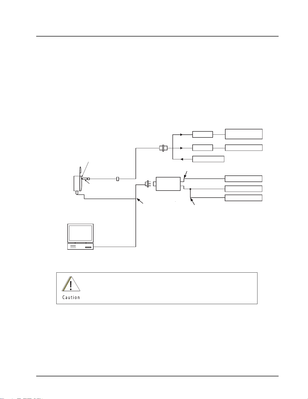
Radio Alignment Procedures: Test Setup 6-1
Chapter 6 Radio Alignment Procedures
This chapter describes both receiver and transmitter radio alignment procedures.
6.1 Test Setup
A personal computer (PC) and tuner software are required to align the radio. Refer to the applicable
manual for installation and setup procedures for the software. To perform the alignment procedures,
the radio must be connected to the PC and to a universal test set. The radio alignment test setup is
shown in Figure 6-1.
b
SYSTEM ANALYZER
OR COUNTER
WATTMETER
TX
AUDIO GENERATOR
RX
SINAD METER
AC VOLTMETER
XTS4000
Radio
30 dB PAD
TRANSMIT
30 dB PAD
Battery Eliminator with
RF connector NNTN7152_
SMA to BNC
RF Adaptor
BNC
RF GENERATOR
RECEIVE
Set to approx. 450mV for Tx
AUDIO IN
TEST SET
RLN-4460
COMPUTER
RS232 XTS4000 Program/
Test Cable NKN1027_
or
USB XTS4000 Program/
Test Cable NKN1029_
Measure 80mV for Tx
Figure 6-1. Radio Alignment Test Setup
These radio alignment procedures should only be attempted by qualified
service personnel. Failure to perform alignment procedures properly may
result in seriously degraded radio or system performance.
6871619L01-C September 10, 2008
Page 44

6-2 Radio Alignment Procedures: Tuner Main Menu
6.2 Tuner Main Menu
Select Tuner from the START menu. To read the radio, use the File › Read Device menu or click on
. Figure 6-2 illustrates how the alignment screens are organized. To access a screen,
double-click on the desired screen name in the Tuner menu.
Figure 6-2. Tuner Software Main Menu
September 10, 2008 6871619L01-C
Page 45

Radio Alignment Procedures: Softpot 6-3
6.3 Softpot
The alignment screens introduce the concept of the “softpot,” an analog SOFTware-controlled
POTentiometer used for adjusting all transceiver alignment controls.
DO NOT switch radios in the middle of any alignment
procedure. Always left-click the Close button on the screen to
return to the Main Menu screen before disconnecting the
radio. Improper exits from the alignment screens might leave
the radio in an improperly configured state and result in
seriously degraded radio or system performance.
Each alignment screen provides the ability to increase or decrease the softpot value by using a slider
or the spin buttons in the New Softpot Value box, or by entering the new value from the keyboard
directly into the box. The slider bar indicates the minimum and maximum values of the softpot, while
the Radio Softpot Value indicates the recommended value; see Figure 6-3 (VHF)/ Figure 6-4 (UHF).
Figure 6-3. Typical Softpot Screen – VHF
Figure 6-4. Typical Softpot Screen – UHF
6871619L01-C September 10, 2008
Page 46

6-4 Radio Alignment Procedures: Radio Information
Adjusting the softpot value sends information to the radio to increase (or decrease) the voltage in the
corresponding circuit. For example, left-clicking the UP spin button in the New Softpot Value scroll
box on the Reference Oscillator screen instructs the radio’s microcomputer to increase the voltage
across a varactor in the reference oscillator, which increases the frequency.
In ALL cases, the softpot value is just a relative number corresponding to a digital-to-analog (D/A)
generated voltage in the radio.
Perform the following procedures in the sequence indicated.
NOTE: Some of the following screens may vary depending upon the radio under test and the version
of tuner software you are using. Refer to the software’s online help.
When keying the radio during a test, always
dummy load.
6.4 Radio Information
Figure 6-5 shows a typical Radio Information screen. This screen is informational only and cannot be
directly changed.
transmit into a
Figure 6-5. Radio Information Screen
6.5 Reference Oscillator Alignment
Adjustment of the reference oscillator is critical for proper radio operation. Improper adjustment will
result not only in poor operation, but also in a misaligned radio that will interfere with other users
operating on adjacent channels. For this reason, the reference oscillator should be checked every
time the radio is serviced, or once a year, whichever comes first. The frequency counter used for this
procedure must have a stability of 0.1 ppm (or better).
NOTE: Reference oscillator alignment is required after replacing (or servicing) the mainboard.
This test can be done with either the R-2670 Communication Analyzer or the 8901_ Modulation
Analyzer.
September 10, 2008 6871619L01-C
Page 47

Radio Alignment Procedures: Reference Oscillator Alignment 6-5
• Initial setup using the R-2670 Communication Analyzer:
– RF Control: MONITOR
– B/W: WB
– Freq: CPS frequency under test
– Attenuation: 20dB
– Mon RF in: RF I/O
– Meter: RF Display
– Mode: STD
– Input Level: uV or W
– Display: Bar Graphs
– Squelch: Mid-range or adjust as necessary
• Initial setup using the 8901_ Series Modulation Analyzer:
– Press the green Automatic Operation button on the analyzer.
– Press the FREQ key.
– Type 7.1 followed by SPCL button to set the 8901B_ modulation analyzer for maximum
accuracy.
To align the reference oscillator:
1. Select the Reference Oscillator alignment screen. See Figure 6-6 (VHF) below/ Figure 6-7
(UHF) on page 6-6.
Figure 6-6. Reference Oscillator Alignment Screen – VHF
6871619L01-C September 10, 2008
Page 48

6-6 Radio Alignment Procedures: Reference Oscillator Alignment
Figure 6-7. Reference Oscillator Alignment Screen – UHF
2. Click the PTT Toggle button to make the radio transmit. The screen indicates whether the
radio is transmitting.
3. Measure the transmit RF frequency with your service monitor.
4. Adjust the reference oscillator’s softpot value until the measured value is as close as possible
to the frequency shown on the screen. See Table 6-1.
Table 6-1. Reference Oscillator Alignment
Band Targ et
VHF ±100 Hz
UHF ±100 Hz
5. Click the Program All button to save the tuned values in the radio.
6. Click the Close button to return to the Transmitter Alignments menu.
September 10, 2008 6871619L01-C
Page 49

Radio Alignment Procedures: Transmit Power Alignment 6-7
6.6 Transmit Power Alignment
This alignment procedure adjusts the transmit power of the radio and must be performed for three
different power levels (Low, Mid, and High), at multiple frequencies for each power level, to allow for
proper alignment across the entire RF band. The RF band is divided into frequency zones with a
calibration point (value) in each zone.
NOTES:
• The same softpot attenuation value will result in different radio output power levels at different
frequencies.
• All power measurements are to be made at the antenna port.
• Transmit Power alignment is required after replacing (or servicing) the mainboard.
RF Connector
Battery Eliminator
To Power Supply
Figure 6-8. Battery Eliminator with RF Connector and SMA
To align transmit power:
1. Select the TX Power (Low, Mid, or High) alignment screen. The screen will indicate the
transmit frequencies to be used. See Figure 6-9 (VHF)/
Figure 6-10 (UHF) on page 6-8.
2. Click the desired frequency field (starting with the highest frequency shown).
3. Click the PTT Toggle button to make the radio transmit. The screen indicates whether the
radio is transmitting.
4. Measure the transmit power of the radio with a service monitor.
5. Adjust the softpot value until the required power, as shown in Table 6-2, is indicated on the
service monitor.
6871619L01-C September 10, 2008
Page 50

6-8 Radio Alignment Procedures: Transmit Power Alignment
Table 6-2. Transmit Power Settings
Power Level
Transmi t
Power
(Watts)
Transmit
Power
(Watts)
VHF UHF
Low 1.2–1.4 0.2–0.3
High 2.2–2.4 2.2–2.4
6. Repeat Steps 2 through 5 for all frequencies and all power levels.
7. Click the Program All button to save the tuned values in the radio.
8. Click the Close button to return to the Transmitter Alignments menu.
Figure 6-9. Transmit Power Alignment Screen (Typical) – VHF
Figure 6-10. Transmit Power Alignment Screen (Typical) – UHF
September 10, 2008 6871619L01-C
Page 51

Radio Alignment Procedures: Transmit Deviation Balance Alignment 6-9
6.7 Transmit Deviation Balance Alignment
This alignment procedure balances the modulation contributions of the low- and high-frequency
portions of a baseband signal. Proper alignment is critical to the operation of signalling schemes that
have very low frequency components (for example, DPL) and could result in distorted waveforms if
improperly adjusted.
This procedure needs to be performed at multiple frequencies to allow for proper alignment across
the entire RF band. The RF band is divided into frequency zones with a calibration point (value) in
each zone.
NOTE: This alignment is required after replacing (or servicing) the main board.
Proper alignment requires a modulation analyzer or meter with a frequency response to less than
10 Hz modulating frequency. The modulation analyzer settings during this test should be set for
average deviation, a 15 kHz low-pass filter, no de-emphasis, and no high-pass filter, if these settings
are supported.
This test can be done with either the R-2670 Communication Analyzer or the 8901_ Series
Modulation Analyzer. The method of choice is the R-2670 analyzer.
1. Initial setup using the R-2670 Communication Analyzer:
– Connect a BNC cable between the “DEMOD OUT” port and the “VERT/SINAD DIST/DMM
COUNTER IN” port on the R-2670.
– Press the SPF key on the R-2670 to display the “SPECIAL FUNCTIONS MENU.” Move the
cursor to “High Pass,” and select 5 Hz on the soft key menu. Select 20 kHz for the “Low Pass”
setting.
– In the “RF Control” section of the R-2670, enter the frequency displayed on the RSS screen.
Move the cursor to the “B/W” setting and select “WIDE +/- 100 kHz” on the soft key menu.
– Place the R-2670 cursor in the “Display” zone. Select “AC VOLTS” on the soft key menu.
Move the cursor to the “Range” setting and select “AUTO.”
2. Initial setup using the 8901_ Series Modulation Analyzer:
– Press the FM MEASUREMENT button. (The “Error 03-input level too low” indication is
normal until an input signal is applied.)
– Simultaneously press the Peak – and Peak + buttons. Both LEDs on the buttons should light.
– Press the 15 kHz LP filter key.
3. Select the TX Deviation Balance alignment screen. The screen indicates the transmit
frequencies to be used. See Figure 6-11 (VHF)/ Figure 6-12 (UHF) on page 6-10.
4. Click the desired frequency field (starting with the highest frequency shown).
5. Click the PTT Toggle button to make the radio transmit. The screen indicates whether the
radio is transmitting.
6871619L01-C September 10, 2008
Page 52

6-10 Radio Alignment Procedures: Transmit Deviation Balance Alignment
Figure 6-11. Transmit Deviation Balance Alignment Screen – VHF
Figure 6-12. Transmit Deviation Balance Alignment Screen – UHF
6. Click the PTT Tone: Low button.
7. Click the PTT Toggle button on the screen to enable transmission. The screen indicates
whether the radio is transmitting. Wait approximately 5 seconds until the voltage shown on
R-2670, or the deviation shown on the 8901_ analyzer, stabilizes.
8. Measure and record the ac voltage value from the R-2670 analyzer or the deviation value
from the 8901_ series analyzer.
9. Left-click the PTT Tone: High button.
September 10, 2008 6871619L01-C
Page 53

Radio Alignment Procedures: Transmit Deviation Limit Alignment 6-11
10. Adjust the softpot value until the measured deviation/voltage, when using the high tone, is
within +/- 1.5% of the value observed when using the low tone.
11. Repeat the above process for all frequencies.
12. Click the Program All button to save the tuned values in the radio.
13. Click the Close button to return to the Transmitter Alignments menu.
6.8 Transmit Deviation Limit Alignment
This alignment procedure limits the modulation of a baseband signal. It is used for primary
modulation limiting.
This procedure needs to be performed at multiple frequencies to allow for proper alignment across
the entire RF band. The RF band is divided into frequency zones with a calibration point (value) in
each zone.
NOTE: This alignment is required after replacing (or servicing) the main board.
This test can be done with either the R-2670 Communication Analyzer or the 8901_ Series
Modulation Analyzer. The method of choice is the R-2670 analyzer.
1. Initial setup using the R-2670 Communication Analyzer:
– Connect a BNC cable between the “DEMOD OUT” port and the “VERT/SINAD DIST/DMM
COUNTER IN” port on the R-2670.
– Press the SPF key on the R-2670 to display the “SPECIAL FUNCTIONS MENU.” Move the
cursor to “High Pass,” and select 5 Hz on the soft key menu. Select 20 kHz for the “Low Pass”
setting.
– In the “RF Control” section of the R-2670, enter the frequency displayed on the RSS screen.
Move the cursor to the “B/W” setting and select “WIDE +/- 100 kHz” on the soft key menu.
– Place the R-2670 cursor in the “Display” zone. Select “AC VOLTS” on the soft key menu.
Move the cursor to the “Range” setting and select “AUTO.”
2. Initial setup using the 8901_ Series Modulation Analyzer:
– Press the FM MEASUREMENT button. (The “Error 03-input level too low” indication is
normal until an input signal is applied.)
– Simultaneously press the Peak – and Peak + buttons. Both LEDs on the buttons should light.
– Press the 15 kHz LP filter key.
6871619L01-C September 10, 2008
Page 54

6-12 Radio Alignment Procedures: Transmit Deviation Limit Alignment
3. Select the TX Deviation Limit alignment screen. The screen will indicate the transmit
frequencies to be used. See Figure 6-13 (VHF)/ Figure 6-14 (UHF) on page 6-12.
Figure 6-13. Transmit Deviation Limit Alignment Screen – VHF
Figure 6-14. Transmit Deviation Limit Alignment Screen – UHF
4. Click the desired frequency field (starting with the highest frequency shown).
5. Click the PTT Toggle button to make the radio transmit. Wait approximately 5 seconds until
the deviation/voltage displayed on the analyzer stabilizes. The screen indicates whether the
radio is transmitting.
6. Adjust softpot value until the measured deviation is as close as possible to 2.83 kHz.
7. Repeat the above process for all frequencies.
September 10, 2008 6871619L01-C
Page 55

Radio Alignment Procedures: Front End Filter Alignment 6-13
8. Click the Program All button to save the tuned values in the radio.
9. Click the Close button to return to the Transmitter Alignments menu.
6.9 Front End Filter Alignment
This procedure should only be attempted by qualified service technicians.
This alignment procedure adjusts the front end receiver bandpass filters for the best receiver
sensitivity and selectivity. This procedure should be performed for all test frequencies to allow for
proper software interpolation of frequencies between the test frequencies in the band
(see Figure 6-16 (VHF) below/ Figure 6-17(UHF) on page 6-14 ).
NOTE: Rx Front End Filter Alignment is required after replacing (or servicing) the mainboard.
RF Connector
Figure 6-15. Battery Eliminator with RF Connector and SMA
6.9.1 Procedure for VHF/ UHF
To align the VHF/ UHF receiver front end:
1. Click the desired frequency field.
2. Apply an RF signal with no modulation at -90 dBm on the current operating frequency.
3. Start with a softpot value (approximately 10 or 20), increase softpot in ascending order, and
note the RSSI values. The RSSI will reach a peak value and remain stable and then
decrease. Allow the limits of the peak range to be defined as RSSI PEAK - 3. Choose the
middle of the peak range and program the corresponding softpot value as the tuned softpot
value.
Battery Eliminator
To Power Supply
6871619L01-C September 10, 2008
Page 56

6-14 Radio Alignment Procedures: Front End Filter Alignment
4. Repeat the above process for all frequencies.
5. Click the Program All button to save the tuned values in the radio.
Figure 6-16. Front End Filter Alignment Screen – VHF
Figure 6-17. Front End Filter Alignment Screen – UHF
September 10, 2008 6871619L01-C
Page 57

Radio Alignment Procedures: Bit Error Rate 6-15
6.10 Bit Error Rate
This section describes the Bit Error Rate (BER) test of the radio’s receiver at a desired frequency
(see Figure 6-18, on page 6-16).
6.10.1 Bit Error Rate Fields
Set up the R2670 Communication Analyzer as follows:
1. Connect the RF Input port of the radio under test to the RF IN/OUT port of the R2670 Service
Monitor.
2. Set up the R2670 Service Monitor:
– In the Display Zone, select PROJ 25 STD mode and set the meter to RF DISPLAY.
– In the RF Zone, configure the analyzer as follows:
RF Control: Generate
Preset: B/W: NB
Freq: Test frequency (Ex: 136.075 MHz/ 380.075 MHz)
Output Level: -50.0 dBm
Gen RF Out: RF I/O
– In the Audio Zone, select the 1011 Hz PAT code and set the deviation to “PROJ25Dev:
2.83 kHz ~”.
The bit error rate screen contains the following fields:
• Rx Frequency:
This field selects the Receive Frequency directly in MHz.
• Test Pattern:
This field selects the Digital test pattern — TIA. Choices are: Standard Tone Test Pattern
(Framed 1011) and Standard Interface Test Pattern (CCITT V.52).
• Modulation Type:
This field represents the digital modulation type of the incoming signal on which BER is to be
calculated.
• Continuous Operation:
This field allows the user the option to repeat the BER test indefinitely. A selection of Yes will
cause the radio to calculate BER on a continuous basis and update the results on this screen
after each integration time. A selection of No will cause the BER test to execute for only one
sample of the integration time and then update the display.
• Audio:
This field allows the user to select the audio output during a test. Selecting Internal will cause
the radio's built-in speaker to unmute to any signals at the desired frequency which are present
during the test. Selecting External will route the same signal to the radio's accessory connector
audio output. Selecting Mute will disable the audio output.
• BER Integration Time:
This field represents the amount of time over which the Bit Error Rate is to be calculated. The
range is from 0.360 to 91.8 seconds in increments of 0.360 seconds.
6871619L01-C September 10, 2008
Page 58

6-16 Radio Alignment Procedures: Transmitter Test Pattern
NOTE: When Continuous Operation = Yes, all fields will be grayed out while the test is in progress.
They will be enabled when the STOP button is pressed.
When Continuous Operation = No, a wait cursor will be displayed while the test is in
progress and return to normal when the test is done.
Figure 6-18. Bit Error Rate Screen
6.11 Transmitter Test Pattern
The Transmitter Test Pattern test is used to transmit specific test patterns at a desired frequency so
that the user can perform tests on the radio’s transmitter (see Figure 6-19 below/
Figure 6-20 on page 6-17).
6.11.1 Transmitter Test Fields
This screen contains the following fields:
• Tx Frequency:
This field selects the Transmit Frequency directly in MHz.
• Channel Spacing:
This field allows the user to select the desired transmit deviation in kHz.
• Test Pattern Type:
This field represents the type of test pattern which will be transmitted by the radio when PTT
TOGGLE button is pressed.
NOTE: Channel Spacing and Test Pattern Type fields will be grayed out while radio is transmitting.
September 10, 2008 6871619L01-C
Page 59

Radio Alignment Procedures: Transmitter Test Pattern 6-17
Figure 6-19. Transmitter Test Pattern Screen – VHF
Figure 6-20. Transmitter Test Pattern Screen – UHF
6871619L01-C September 10, 2008
Page 60

6-18 Radio Alignment Procedures
Notes
September 10, 2008 6871619L01-C
Page 61

Encryption: Load an Encryption Key 7-1
Chapter 7 Encryption
This chapter provides procedures for using the encryption capability of your radio. The following
procedures are outlined:
• Loading an encryption key
• Selecting an encryption key
• Selecting an Index
• Erasing an encryption key
7.1 Load an Encryption Key
To load an encryption key:
1. Refer to the key-variable loader (KVL) manual for equipment connections and setup.
2. Attach KVL to the bottom connector of the radio using Keyload cable 0182297T15. The
display shows “KEYLOADING.” All other radio functions, except for power down, backlight, and
volume, are locked out.
3. Refer to the KVL manual for how to load the encryption keys into the radio.
4. When the key is loaded successfully, you will hear:
• On single-key radios—a short tone.
• On multikey radios—an alternating tone.
7.2 Multikey Feature
This feature allows the radio to be equipped with multiple encryption keys. It can support up to two
different encryption algorithms simultaneously (e.g., DVP-XL and DES-XL).
• Conventional Multikey — The encryption keys can be tied (strapped), on a one-per-channel
basis. In addition, the radio can have operator-selectable keys, operator-selectable indices, and
operator-selectable key erasure. If talkgroups are enabled in conventional, then the encryption
keys are strapped to the talkgroups.
• Trunked Multikey — If the radio is used for both conventional and trunked applications, strap
the encryption keys for trunking on a per- talkgroup or announcement group basis. In addition,
a different key can be strapped to other features; for example, dynamic regrouping, failsoft, or
emergency talkgroup. The radio can have operator-selectable key erasure.
7.3 Select an Encryption Key
You can select an encryption key using either the menu or the keypad.
7.3.1 Use the Menu
To select an encryption key using the menu:
1. Press Right Navigation Button until the display shows “KEY.”
2. Press Left Menu Select Button, Middle Menu Select Button, or Right Menu Select
Button, directly below “KEY.” The display shows the last user-selected and stored encryption
key, as well as the available menu selections.
6871619L01-C September 10, 2008
Page 62

7-2 Encryption: Select an Encryption Index
3. Press Left Navigation Button or Right Navigation Button to scroll through the list of
encryption keys.
NOTE: If you select an erased key, the display alternates between showing the encryption
key and “ERASED KEY.”
4. Press Left Menu Select Button, Middle Menu Select Button, or Right Menu Select
Button directly below the desired menu.
• PSET = selects the preset or default encryption key.
• SEL = saves the newly selected key and returns to the home display.
5. Press Home Button, the PTT Button, or Left Menu Select Button, Middle Menu Select
Button, or Right Menu Select Button directly below the ABRT menu to exit this menu.
• If the selected key is erased, the display shows “KEY FAIL” and the radio sounds a
momentary keyfail tone.
• If the selected key is not allowed, the display shows “ILLEGAL KEY” and the radio sounds a
momentary illegal key tone.
7.3.2 Use the Keypad
To select an encryption key using the keypad:
1. Press Right Navigation Button until the display shows “KEY.”
2. Press Left Menu Select Button, Middle Menu Select Button, or Right Menu Select
Button directly below “KEY.” The display shows the last user-selected and
-stored encryption key, as well as the available menu selections.
3. Using the keypad, enter the number of the desired key.
NOTE: If you select an erased key, the display alternates between showing the encryption
key and “ERASED KEY.”
4. Press Left Navigation Button or Right Navigation Button to select from the menu.
• PSET = selects the preset or default encryption key.
• SEL = saves the newly selected key and returns to the home display.
5. Press h, the PTT Button, or Left Menu Select Button, Middle Menu Select Button, or
Right Menu Select Button directly below the ABRT menu.
• If the selected key is erased, the display shows “KEY FAIL” and the radio sounds a
momentary keyfail tone.
• If the selected key is not allowed, the display shows “ILLEGAL KEY” and the radio sounds a
momentary illegal key tone.
7.4 Select an Encryption Index
This feature lets the user select one or more groups of several encryption keys from among the
available keys stored in the radio. For example, the radio could have a group of three keys structured
to one index, and another group of three different keys structured to another index. Changing indices
makes the radio automatically switch from one set of keys to the other. Every channel to which one
of the original keys was tied will now have the equivalent new key instead.
September 10, 2008 6871619L01-C
Page 63

Encryption: Erase an Encryption Key 7-3
7.4.1 Use the Menu
To select an index using the menu:
1. Press Right Navigation Button until the display shows “INDX.”
2. Press Left Menu Select Button, Middle Menu Select Button, or Right Menu Select
Button directly below “INDX.” The display shows the last user-selected and stored index, as
well as the available index menu selections.
3. Press Left Menu Select Button, Middle Menu Select Button, or Right Menu Select
Button directly below the desired index. The display shows the last user- selected and stored index, as well as the available index menu selections.
4. Choose one of the following:
a. To save the index, press Left Menu Select Button, Middle Menu Select Button, or
Right Menu Select Button directly below “SEL.”
b. To exit this menu without changing the index selection, press Home Button or the PTT
Button.
7.4.2 Use the Keypad
To select an index using the keypad:
1. Press Right Navigation Button until the display shows “INDX.”
2. Press Left Menu Select Button, Middle Menu Select Button, or Right Menu Select
Button directly below “INDX.” The display shows the last user-selected and
-stored index, as well as the available index menu selections.
3. Using the keypad, enter the number of the desired index.
4. Choose one of the following:
a. To save the index, press Left Menu Select Button, Middle Menu Select Button, or
Right Menu Select Button directly below “SEL.”
b. To exit this menu without changing the index selection, press Home Button or the PTT
Button.
7.5 Erase an Encryption Key
This section describes two methods for erasing an encryption key.
7.5.1 Method 1 – Key Zeroization (Multikey Only)
To zeroize an encryption key:
1. Press Right Navigation Button until the display shows “ERAS.”
2. Press Left Menu Select Button, Middle Menu Select Button, or Right Menu Select
Button directly below “ERAS.” The display shows the last user-selected and
-stored encryption key, as well as the available menu selections that are listed in Table 7-1.
3. Choose one of the following:
• If you want to erase all the encryption keys at once, go to section 7.5.2: ”Method 2 – All
Keys Erased” on page 7-4 below.
• If you want to erase a single encryption key, do one of the following:
– Press Left Navigation Button or Right Navigation Button to find the desired key. The
display shows the selected key and the available menu selections shown in Table 7-1.
6871619L01-C September 10, 2008
Page 64

7-4 Encryption: Erase an Encryption Key
– Using the keypad, enter the location number of the desired key. The display shows the
selected key, as well as the available menu selections shown in Table 7-1.
Table 7-1. Encryption Key Zeroization Options
Menu
Selection
ALL Erases all the encryption keys in the radio. The display
shows “ERS ALL KEYS” and “YES” and “NO.”
SNGL Selects the displayed encryption key to be erased.The
display shows “ERS SNGL KEY” and “YES” and “NO.”
ABRT Exits this menu and returns to the home display
NOTE: To exit this menu at any time without erasing the key selection, press Home Button
or the PTT Button.
4. Press Left Menu Select Button, Middle Menu Select Button, or Right Menu Select
Button directly below the desired menu selection.
5. Press Home Button or the PTT Button to exit this menu.
7.5.2 Method 2 – All Keys Erased
To erase all encryption keys at one time:
With the radio on, press and hold the Secure Button (Programmable, Top Left Button)
and, while holding this button down, press the Emergency Button (Programmable, Top
Right Orange Button).
NOTE: DO NOT press the Emergency Button (Programmable, Top Right Orange
Button) before pressing the Secure Button (Programmable, Top Left Button)
unless you are in an emergency situation. This sends an emergency alarm.
Action
Before the keys are erased, the display shows “PLEASE WAIT.”
When all the encryption keys have been erased, the display shows “ALL KEYS ERASED.”
September 10, 2008 6871619L01-C
Page 65

Disassembly/Reassembly Procedures: XTS 4000 Exploded View (Partial) 8-1
Chapter 8 Disassembly/Reassembly Procedures
This chapter provides detailed procedures for disassembling/reassembling XTS 4000 radios. When
performing these procedures, refer to “Chapter 10: Exploded Views and Parts Lists” on page 10-1
and the diagrams that accompany the text. Items in parentheses ( ) throughout this chapter refer to
item numbers in the exploded view diagrams and their associated parts lists.
8.1 XTS 4000 Exploded View (Partial)
This section contains the XTS 4000 radio partially exploded view and parts list.
NOTES:
• Refer to Figure 8-1 on page 8-2, the Partial Exploded View, and Table 8-1 on page 8-2, the
Corresponding Exploded View and Parts List.
• Numbers in parentheses ( ) refer to item numbers in Figure 8-1 and Table 8-1 on page 8-2.
• The Battery Assembly (E) and Antenna Assembly (D) should be removed from the radio before
disassembly or reassembly the radio.
6871619L01-C September 10, 2008
Page 66

8-2 Disassembly/Reassembly Procedures: XTS 4000 Exploded View (Partial)
D
E
C
A
B
Figure 8-1. XTS 4000 Partial Exploded View
Table 8-1. Corresponding XTS 4000 Exploded View and Parts List
Item
Number
A Flip Assembly Refer “10.2 Exploded View and Parts List –
Description Exploded View and Parts List
Flip-Front Housing Assemblies” on page 10-3.
B Front Housing
Assembly
C Chassis Assembly Refer “10.3 Exploded View and Parts List –
Refer “10.2 Exploded View and Parts List –
Flip-Front Housing Assemblies” on page 10-3.
Chassis Assembly” on page 10-4.
D Antenna Assembly Refer “10.1 Exploded View and Parts List –
Main Assemblies” on page 10-2.
E Battery Assembly Refer “10.1 Exploded View and Parts List –
Main Assemblies” on page 10-2.
September 10, 2008 6871619L01-C
Page 67

Disassembly/Reassembly Procedures: Required Tools and Supplies 8-3
8.2 Required Tools and Supplies
Table 8-2. Required Tools and Supplies
Tools and Supplies
Anti-static ground kit 0180386A82
Magnetic screwdriver set with bits 0180320B16
Tape, Top and Side Controls
Assembly Aid
Black Stick – Hexacon Electric Co. MA-800G
Analog Torque Driver (1-6 in-lbs) Tohnichi 6RTD-A
T3IP, T6IP, and T7IP Torx bits –
Audio Jack Assembly Tool 6671241M01
Tweezers –
Motorola Part
Number
1171742L01
Supplier
Supplier Part
Number
8.3 Fastener Torque Chart
Ta bl e 8 -3 lists the various fasteners by part number and description, followed by the torque values
and the location where used. Torque all fasteners to the recommended value when assembling the
radio.
Table 8-3. Fastener Torque Chart
Motorola
Part Number
0371903L01 Flip Assembly Screw (5) 1.5
0371907L01 Antenna Bushing Screw (43)
Keypad Backer Screw (18)
0371711L01 Battery Connector Screw (45) 1.1
0371904L01 Chassis Screw (49) 4.4
Description
Repair Torque
(in-lbf)
2.1
3.1
6871619L01-C September 10, 2008
Page 68

8-4 Disassembly/Reassembly Procedures: Antenna
8.4 Antenna
This section explains how to attach and remove the antenna.
8.4.1 Attach the Antenna
To attach the antenna:
With the radio turned off, turn the antenna clockwise to attach it to the radio.
8.4.2 Remove the Antenna
To remove the antenna:
With the radio turned off, turn the antenna counter-clockwise to remove it from the radio.
Figure 8-2. Attaching the Antenna
Figure 8-3. Removing the Antenna
September 10, 2008 6871619L01-C
Page 69

Disassembly/Reassembly Procedures: Battery 8-5
8.5 Battery
This section explains how to properly attach and remove the battery.
To avoid a possible explosion:
• DO NOT charge, remove, or attach the battery in an area
labeled “hazardous atmosphere.”
• DO NOT discard batteries in a fire.
If the radio is programmed for volatile-key retention,
encryption keys will be retained for approximately 30 seconds
after battery removal.
NOTE: The Motorola-approved battery shipped with the XTS 4000 radio is uncharged. Prior to using
a new battery, charge it for a minimum of 16 hours to ensure optimum capacity and
performance.
8.5.1 Attach the Battery
To attach the battery:
1. With the radio turned off, insert the bottom edge of the battery into the slot at the back of the
Main Chassis as shown.
step 2
NOTE: Do not attach the battery without engaging the bottom tabs to prevent damage to the battery
or the radio
2. Rotate the battery toward the radio and press down until the battery clicks into place.
8.5.2 Remove the Battery
step 1
Figure 8-4. Attaching the Battery
To remove the battery:
1. With the radio turned off, press the release button on the top of the battery until the battery
releases from the radio.
6871619L01-C September 10, 2008
Page 70

8-6 Disassembly/Reassembly Procedures: Radio Disassembly
2. Rotate and remove the battery from the radio.
release button
Figure 8-5. Removing the Battery
8.6 Radio Disassembly
This section contains instructions for disassembling the radio. For this section, please refer to
“10.1 Exploded View and Parts List – Main Assemblies” on page 10-2,“10.2 Exploded View and
Parts List – Flip-Front Housing Assemblies” on page 10-3 and “10.3 Exploded View and Parts List –
Chassis Assembly” on page 10-4.
IMPORTANT:When servicing radio parts
steps of the proper section depending on the location of the specific components
location.
To service components in Chassis Assembly (C), refer section 8.6.2 "Disassemble the
Chassis Assembly".
To service components in Front housing Assembly (B), refer section 8.6.3
"Disassemble the Front Housing Assembly".
To service components in Flip assembly (A), separate the flip assembly from Front
Housing Assembly (B) by completing steps 1 to10 but skip steps 7-8 in section 8.6.3,
then refer section 8.6.4 "Disassemble the Flip Assembly".
*
Exceptions: CID Bezel (1), Battery Ground redundant Contact (44), Battery
Connector Screw (45), 5Ohm RF Dust Cap Seal (46), Port Seal (47),
Audio Jack PC Label (48) and Chassis Screw (49).
†
Completion of ALL the steps in each section is NOT necessary depending on the
component to be serviced.
*
listed in Chapter 10, complete section 8.6.1 followed by the
†
†
†
For example: to service the main board, after completing all steps in section 8.6.1,
continue step 1-4 in section 8.6.3 to have access till main board level, after that
complete the reassemble steps per describe in their respective section in Radio
Reassembly.
September 10, 2008 6871619L01-C
Page 71

Disassembly/Reassembly Procedures: Radio Disassembly 8-7
8.6.1 Separate the Flip-Front Housing and Chassis Assemblies
To separate the Flip-Front Housing Assembly (A+B) from the Chassis Assembly (C):
1. Turn off the radio by holding down the Power Button for 3 seconds.
2. Remove the Antenna Assembly (D), Battery Assembly (E) or any accessory connected to the
radio.
3. Remove the 5 chassis screws (49) from the back of the radio with a Torx T7 bit driver.
4. Insert the Black Stick (refer “8.2 Required Tools and Supplies” on page 8-3 for part number).
into the groove between the Front Housing and the Control Band (20) near the top (opposite
of PTT area). Gently tilt to separate the Flip-Front Housing Assembly from the Chassis
Assembly.
Black Stick
Figure 8-6. Separating Flip-Front Housing Assembly From Chassis Assembly
5. Lay both sub-assemblies (A+B and C) side by side on the anti-static mat (part of anti-static
ground kit. Refer “8.2 Required Tools and Supplies” on page 8-3 for part number). Gently
unplug the Keypad Backer Inner Jumper Flex (17) from the Main Board (29). Also gently
unplug the CE-UCM Connector Flex (28) from the XTS4000 UCM Board (10) located at the
bottom of the Front Housing Assembly (B) as shown in Figure 8-7.
When separating the flexes and small interconnects, care is
needed to avoid damage to the interconnect and surrounding
on-board components.
6871619L01-C September 10, 2008
Page 72

8-8 Disassembly/Reassembly Procedures: Radio Disassembly
Figure 8-7. Unplugging Flexes
8.6.2 Disassemble the Chassis Assembly
To disassemble the chassis (C):
1. Gently disconnect the CE-UCM Connector Flex (28) from the Main Board (29).
Figure 8-8. Disconnecting CE-UCM Connector Flex and Lifting Main Board
September 10, 2008 6871619L01-C
Page 73

Disassembly/Reassembly Procedures: Radio Disassembly 8-9
2. Lift up the Main Board (29) from the bottom of the Main Chassis (39) and rotate 90° towards
the chassis top side.
Figure 8-9. Rotating Main Board 90° and Unplugging Top Control Inner Jumper Flex
3. Unplug the Top Control Inner Jumper Flex (33) from the top of the Main Board (29).
4. Remove the Main Board (29) and lay it aside. The B Plus Seal (31) may be removed from the
B Plus Connector on the back of the Main Board (29).
5. Use the tweezers to remove the center Screw Seal (32) from the Main Chassis (39).
6. Flip open the Audio Jack Dust Cover (22) and the CE Connector Dust Cover (21) from the
Control Band (20).
Removing the Control Band (20) from the Main Chassis (39)
without disengaging the dust covers may damage the Control
Band.
When removing the control band, make sure the Side and Top
Control Flex (40) and the metal dome array mylar is not
damage during the disassembly.
6871619L01-C September 10, 2008
Page 74

8-10 Disassembly/Reassembly Procedures: Radio Disassembly
7. Hold the chassis with the back facing up; push down the Control Band (20) on the PTT side
so that the latches are unlocked from the Main Chassis (39). Gently pull the Control Band
side outwards to disengage the Control Band. Rotate the Control Band anti-clockwise along
the antenna axis to remove it totally from the Main Chassis (39).
2. Pull gently
1. Push the catches
towards the chassis
Figure 8-10. Removing Control Band
8. Separate the Top and Side Controls Buttons (23+24) from the Control Band (20).
9. Rotate the tab behind the Audio Jack Dust Cover (22) 90°. Pull the Audio Jack Dust Cover
tab out from the Control Band (20) opening as shown in Figure 8-11. Push the tab behind the
CE Connector Dust Cover (21) down. Rotate the tab 90° and pull the dust cover out from the
Control Band as shown in Figure 8-12.
.
Push the
tab out from
the Control Band
Rotate 90°
Figure 8-11. Removing Audio Jack Dust Cover
September 10, 2008 6871619L01-C
Page 75

Disassembly/Reassembly Procedures: Radio Disassembly 8-11
B
Push the tab down
Rotate 90°
Push the
tab out from
the Control
Figure 8-12. Removing CE Dust Cover
10. Gently disengage the snap on Audio Jack Insulator (38). Place the tip of the tweezers at
bottom of Insulator ring. With one hand, push the Insulator tab through the chassis hole while
simultaneously pressing down and pulling out the Insulator ring with the tweezers. Using the
tweezers, grip the sides of the Audio Jack Alignment Sleeve (25) and pull straight out to
remove.
Figure 8-13. Removing Audio Jack
11. Use a tweezer to peel off the Audio Jack PC Label (48) and the Gore Membrane (47) from
the back of the Main Chassis (39).
12. Unplug the CE-UCM Connector Flex (28) from the Audio Jack Board (26) and push the Audio
Jack Board out from the Main Chassis (39) with the help of the Black Stick.
13. Unplug the female connector on the Top Control Inner Jumper Flex (33) from the Side and
Top Control Flex (40). Peel off the Side and Top Control Flex (40) from the Main Chassis
(39).
NOTE: Once the Side and Top Control Flex (40) is removed, replaced it with a new one.
Locate them accordingly to the top control locator pin on then the side control
locating features on the casting.
6871619L01-C September 10, 2008
Page 76
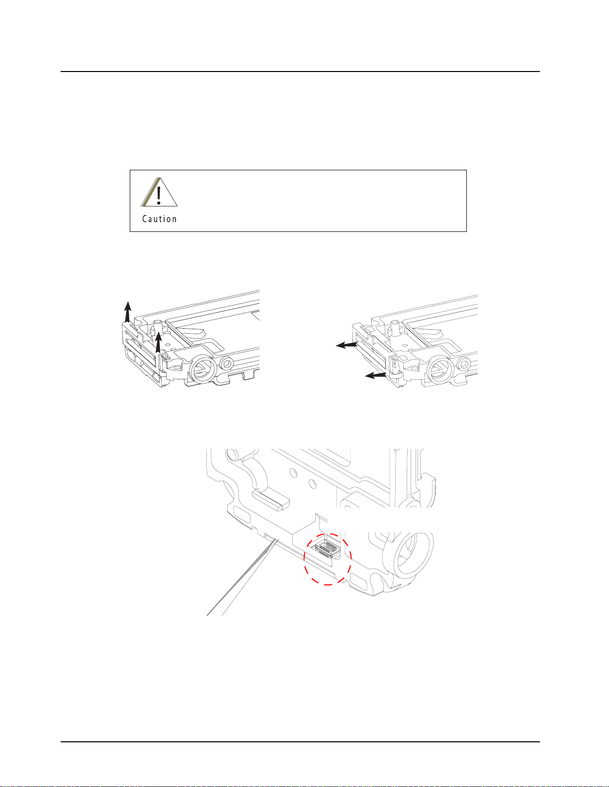
8-12 Disassembly/Reassembly Procedures: Radio Disassembly
14. Unplug the female connector of the CE-UCM Connector Flex (28) from the CE Connector
Board (36) at the bottom of the Main Chassis (39) to remove the CE-UCM Connector Flex.
15. To remove the Bottom CE Retainer (34) from the Main Chassis (39), push the CE Retainer
towards the front side of the Main Chassis direction until it stops. Then remove it together
with the CE Spacer (35) by directing it away from the bottom of the casting (refer Figure 8-
14). Use the tweezers to peel off the CE Connector Board (36) as shown in Figure 8-15.
Avoid inserting the tweezers into the connector area of the CE
Connector Board (36).
Gently push upwards
Direct out from
casting
Figure 8-14. Removing CE Retainer and Spacer
Avoid inserting tweezers
to the connector area
Figure 8-15. Removing CE Board
16. Loosen the top screw (43) on the Antenna Bushing Assembly (42) with a Torx T6 bit torque
driver and remove the Antenna Bushing Assembly.
17. Remove the Battery Connector Screw (45) with a Torx T3 bit torque driver and separate the
Battery Ground Redundant Contact (44).
September 10, 2008 6871619L01-C
Page 77

Disassembly/Reassembly Procedures: Radio Disassembly 8-13
8.6.3 Disassemble the Front Housing Assembly
To disassemble the Front Housing Assembly (B):
1. Remove the Main Seal (19) from the Keypad Backer Sub-Assembly (15).
2. Remove the 4 screws from the Keypad Backer Sub-Assembly with a Torx T6 bit.
3. Remove the Keypad Backer Sub-Assembly by gently tilting the bottom part of the backer out
from the Front Housing, then tongue out from the top of the Front Housing.
Do not twist or pull the Flip Flex as this might cause
permanent damage to the Flip Flex.
Steps 4-6 (Speaker Compartment Seal (13), Main Keypad
(12), and UCM Module) should be performed while supporting
the keypad backer in the orientation shown in Figure 8-16.
4. Remove the Speaker Compartment Seal (13) from the Keypad Backer Sub-Assembly (15).
5. Remove the Main Keypad (12) from the Front Housing. Gently separate the connection
between the Speaker Flex and the UCM Board (10) and remove the UCM Board.
6. Carefully separate the Flip Flex (2) from the Keypad Backer Sub-Assembly (15) by gently
working the flat head of the Black Stick around the perimeter of the Flip Flex stiffener. Detach
the adhesive area of the Flip Flex from the Front Housing.
Step 4
Step 5
Figure 8-16. Disassemble Speaker Compartment Seal, Main Keyboard and UCM Board
6871619L01-C September 10, 2008
Page 78
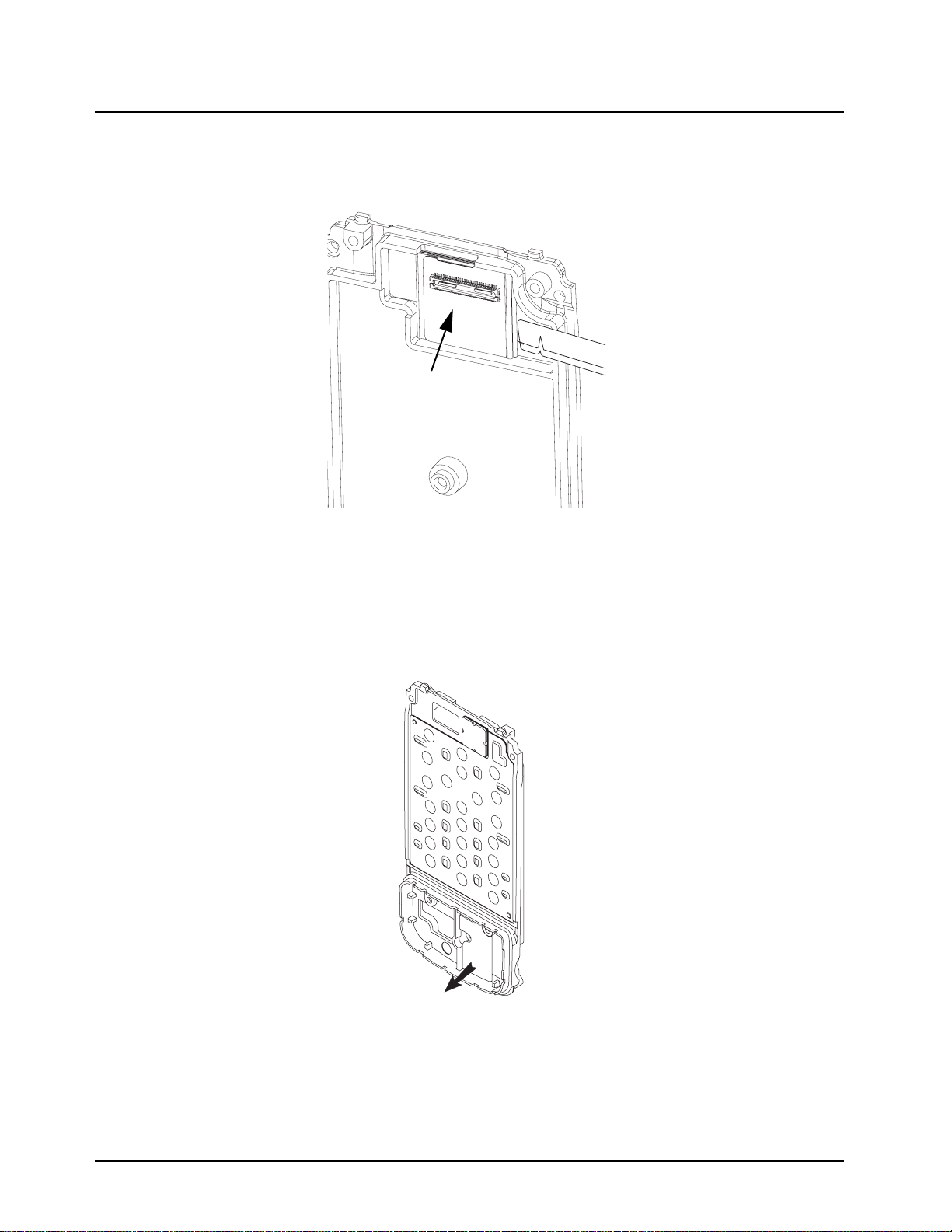
8-14 Disassembly/Reassembly Procedures: Radio Disassembly
7. Separate the Keypad Backer Inner Jumper Flex (17) from the Keypad Backer Sub-Assembly
(15) by gently sliding the flat end of the Black Stick under the flex beginning from the side of
the flip fold.
Keypad Inner Jumper Flex
Figure 8-17. Separating Keypad Backer Inner Jumper Flex
NOTE: Once the Keypad Backer Inner Jumper Flex (17) and/or Audio Jack Pad (16) are
removed, replaced with new ones. If the Keypad Backer and/or Main Keypad Flex
requires servicing, replace with NNTN7100A - Assembly, Keypad Backer.
8. Remove the Audio Jack Pad (16) and Secure Pad (14) as shown in Figure 8-18.
Figure 8-18. Removing Secure Pad
September 10, 2008 6871619L01-C
Page 79
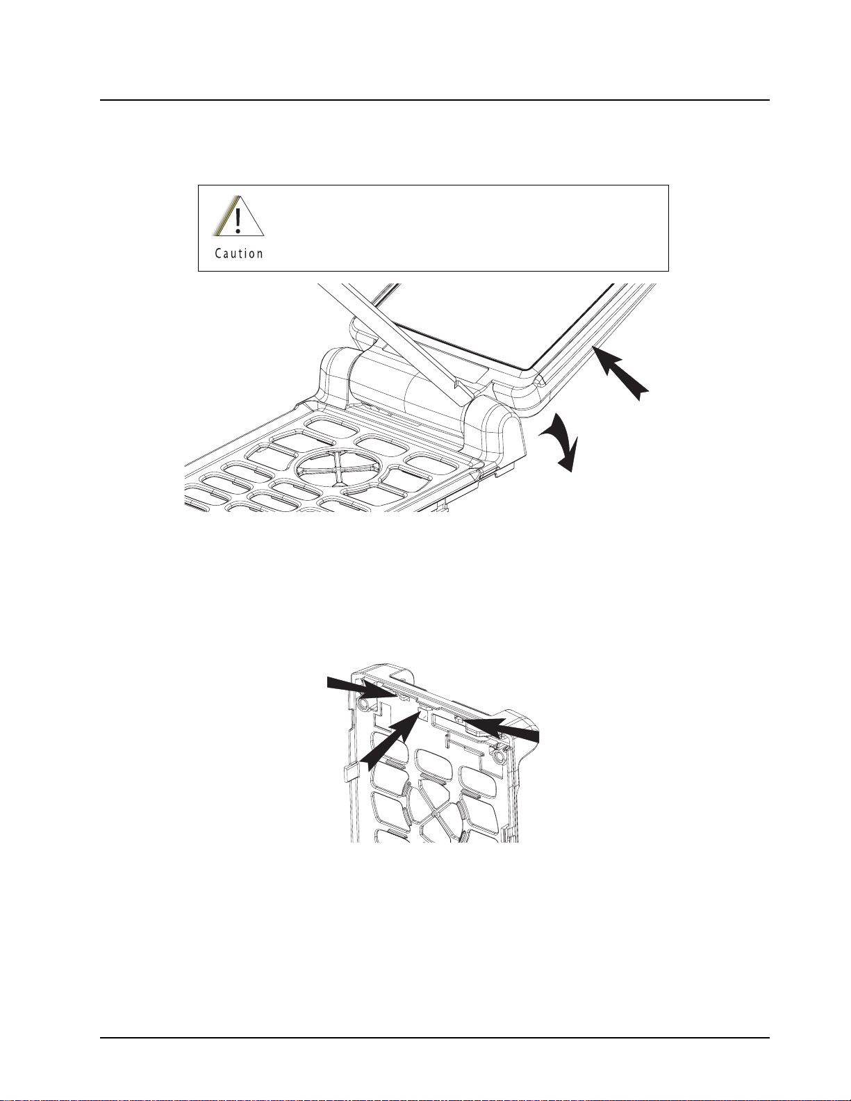
Disassembly/Reassembly Procedures: Radio Disassembly 8-15
9. With the flip in the open position, insert the flat end of the Black Stick between the flip
assembly (A) and the Front Housing. With a corner of the Black Stick positioned as shown in
Figure 8-19, gradually increase the gap between the Flip Assembly and Front Housing by
twisting the Black Stick until the Flip Assembly separates.
Do not twist or pull the Flip Flex as this might cause
permanent damage to the Flip Flex.
Figure 8-19. Removing Front Housing from Flip Assembly
10. Put the Flip Assembly (A) aside. Remove the Flip Bumper Pad (11) from the Front Housing.
11. Remove each tab of the Flip Stopper Pad (7) as shown in Figure 8-20. Using the flat end of
the Black Stick, slide the tab while simultaneously pushing it through the opening in the Front
Housing. Then, pull the flip stopper from the side of the front housing to remove the flip
stopper.
Figure 8-20. Removing Tabs from Flip Stopper Pad
6871619L01-C September 10, 2008
Page 80
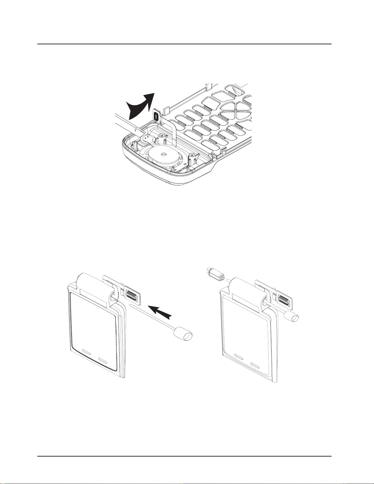
8-16 Disassembly/Reassembly Procedures: Radio Disassembly
12. Remove the Microphone Boot (8*) and microphone from the Front Housing by gently lifting
the Microphone Boot from the side with the flat end of the Black Stick as shown in
Figure 8-21. Separate the Microphone Boot from the microphone.
Figure 8-21. Removing Microphone Boot and Microphone from Front Housing
8.6.4 Disassemble the Flip Assembly
To disassemble the flip assembly (A):
1. Slowly insert the Audio Jack Assembly Tool (refer “8.2 Required Tools and Supplies” on
page 8-3 for part number) into the Flip Flex opening of the Flip Assembly (A), while
positioning the Flip Flex (2) above the tool as shown in Figure 8-22. Lightly push the tool
towards the Hinge (4) to separate the hinge from the Flip Assembly.
Figure 8-22. Separating Hinge from Flip Inner Housing
2. Peel off the Flip Inner Label (6) from the Flip Sub-Assembly (3) with a tweezers. With the CID
Bezel Kit (1) facing down, remove the 2 screws with a Torx T6 bit.
September 10, 2008 6871619L01-C
Page 81

Disassembly/Reassembly Procedures: Radio Reassembly 8-17
3. Insert the pointed tip of the Black Stick into one of the screw holes to push out the CID Bezel
Kit (1).
Extreme care must be taken during removal of the CID Bezel Kit
(1), particularly near the thin ribs adjacent to the CID Display.
4. Insert the flat part of the Black Stick between the CID Bezel Kit (1) and the Flip Sub-Assembly
(3), slowly and gently sweep downwards to release the adhesive of the CID Bezel Kit (1) from
the Flip Sub-Assembly.
Gently sweep
in this direction
5. Remove the CID Bezel Kit (1) from the tongue in area of the Flip Sub-Assembly (3).
6. Use the flat end of the black stick to remove the adhesive between the Flip Flex (2) and outer
flip housing and to unplug the Flip Flex from the Display Module flex connector.
NOTE: The Flip Flex cannot be reused after removed. It must be replaced with a brand new part.
7. Gently pull out the Flip Flex (2) from the hinge compartment of the Flip Sub-Assembly (3).
8.7 Radio Reassembly
This section contains instructions for reassembling the radio.
All disassembled interfaces requiring adhesive must have new
adhesive applied during reassembly. The adhesive surfaces must be
clean and free of all foreign material, including oils and/or any
remaining adhesive after disassembly. If necessary, the surfaces
may be cleaned using a 0.5% solution of a mild dishwashing
detergent in water applied sparingly to the surface, ensuring that no
water enters into adjacent openings (connectors or otherwise),
cracks, or crevices. Remove the solution and dry the surface using a
lintless cloth or tissue. All newly applied adhesive interfaces should
be press fit for 10 seconds to ensure sealing capability is retained.
CID Display
Figure 8-23. Removing CID Bezel
6871619L01-C September 10, 2008
Page 82

8-18 Disassembly/Reassembly Procedures: Radio Reassembly
8.7.1 Reassemble the Flip Assembly
To reassemble the flip assembly (A):
NOTE: Unless the Flip Flex (2) is replaced, otherwise, new adhesives must be applied using material
from the Field Service Kit – Adhesive (NNTN7189_) whenever any adhesive is removed from
the Flip Flex.
.
1
2
Item 4 align to
these 2 edges
Item 3 align to
legend marking
& edge
This cut
indicate up
Item 5 align to
these 2 edges
B
Adhesive Location – Front View
5
4
3
Item 1 align to
these 2 edges
Adhering the Adhesive to Flip Flex – Overview
Item
No.
Motorola
Part number
Description
1 1171646L01 Adhesive, Flip Flex Seal 2
(Flip)
2 7571858L01 Pad, Conductive Foam
3 1171845L01 Adhesive, Flip Flex
Housing
4 1171857L01 Adhesive, Conductive
5 1171645L01 Adhesive, Flip Flex Seal 1
(Backer)
Figure 8-24. Flip Flex
1. Prepare adhesives surfaces of the Flip Assembly as described in first caution note of Section
“8.7 Radio Reassembly” on page 8-17.
Items 2 align to
arrow marking & edge
THIS SIDE UP
Adhering the Adhesive to Flip Flex – Overview
September 10, 2008 6871619L01-C
Page 83

Disassembly/Reassembly Procedures: Radio Reassembly 8-19
2. Carefully insert the Flip Flex (2) into the hinge compartment of the Flip Sub-Assembly (3) as
shown in Figure 8-25.Peel off the liner of the adhesive at the new Flip Flex (2) connector area
and plug in the Flip Flex to the display module. Press fit for 10 seconds to ensure the
adhesive is properly activated.
Figure 8-25. Inserting Flip Flex
3. Get a new CID Bezel Kit (1), remove all the liners of the adhesives.
4. Tongue in the CID Bezel Kit (1) into the Flip Sub-Assembly (3), rotating the screw bosses into
the receive holes as shown in Figure 8-26. Press fit for 10 seconds to ensure adhesive
functionality.
Figure 8-26. Tongue in CID Bezel into Flip Sub-Assembly
5. With the CID Bezel Kit (1) facing down, assemble the 2 screws near the hinge compartment
with a Torx T6 bit at 1.5 ± 0.2 in-lbf.
6. Prepare the Flip Inner Housing label surface as described in the first caution note of Section
“8.7 Radio Reassembly” on page 8-17. Adhere a new Flip Inner Label (6) to the
Flip Sub-Assembly (3), covering the screws.
7. Push the hinge into the opening of the Flip Assembly (A) until it snaps in place.
8.7.2 Reassemble the Front Housing Assembly
To reassemble the Front Housing Assembly (B):
1. Carefully insert each tab of the Flip Stopper Pad (7) into the corresponding openings of the
Front Housing. Verify that the stopper is fully seated.
6871619L01-C September 10, 2008
Page 84

8-20 Disassembly/Reassembly Procedures: Radio Reassembly
2. While holding the Flip Assembly (A), feed the Flip Flex (2) through the top opening of the
Front Housing.
3. With the flip in the open position, assemble the Flip Assembly as follows:
Be careful not to pull or pinch the Flip Flex during the
assembling process.
a. Guide the Flip Assembly onto the left knuckle of the Front Housing. Ensure the flip flex is
fully inserted in the opening hole of the left knuckle.
b. Gently open a gap on the right knuckle of the Front Housing while simultaneously pushing
the Flip Assembly to engage the Hinge. Simultaneously press on the side of both knuckles
and rotate the flip to ensure the hinge is fully inserted into the front housing slot.
4. Peel off the liner of the Flip Flex as shown in Figure 8-27. Rotate the flex into position
between the Front Housing alignment tabs. Press fit for 10 seconds to ensure the adhesive is
properly activated.
Figure 8-27. Adhere Flip Flex into Front Housing
5. Insert the Microphone Boot (8*) into the Front Housing. Gently push the Microphone into the
Microphone Boot. Verify that the Microphone is fully seated.
6. Assemble the Flip Bumper Pad (11) by inserting and fully depressing the tabs into the
openings of the Front Housing located in the region between the Keypad and the Speaker
Flex compartment.
NOTE: Be careful not to stress the board when plugging the Speaker Flex Connector to the
UCM board (10).
September 10, 2008 6871619L01-C
Page 85

Disassembly/Reassembly Procedures: Radio Reassembly 8-21
7. Assemble the Main Keypad (12) to the Front Housing. Plug in the Speaker Flex Connector to
the UCM board (10) with the board position as shown in Figure 8-28. Rotate the UCM board
(10) into the front housing between the screw bosses and alignment tab.
1. Plug in Connector
2. Rotate
Figure 8-28. Reassemble UCM Board
NOTE: If the Main Keypad Flex and Keypad Backer Sub-Assembly (15) were replaced,
skip step 8 and step 9.
8. Remove the liner of the Keypad Backer Inner Jumper Flex (17). Prepare the Keypad Backer
Sub-Assembly (15) surface as discussed in the first caution note of Section “8.7 Radio
Reassembly” on page 8-17. Plug in the connector of the Keypad Backer Inner Jumper Flex
(17) to the Main Keypad flex male connector from the back of Keypad Backer Sub-Assembly.
Ensure the flex is fully seated by rubbing over the entire area.
9. Attach the Audio Jack Pad (16) and the Secure Pad (14) to the Keypad Backer SubAssembly (15).
Align to these two
side walls when
adhering the
Secure Pad (14)
Figure 8-29. Attach Secure Pad to Keypad Backer Sub-Assembly
6871619L01-C September 10, 2008
Page 86
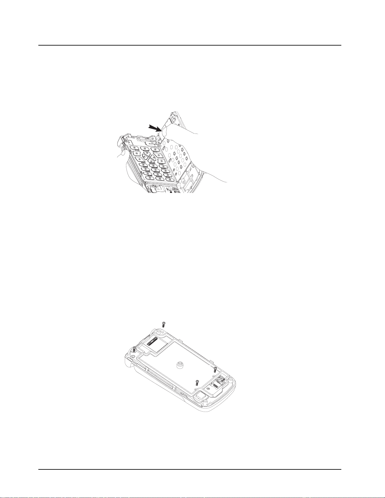
8-22 Disassembly/Reassembly Procedures: Radio Reassembly
10. Prepare the surface of the Keypad Backer Sub-Assembly (15) as discussed in the first
caution note of Section “8.7 Radio Reassembly” on page 8-17. Remove the 2 liners from the
connector area of the Flip Flex (2). While holding the Front Housing Assembly (B) in one
hand and the Keypad Backer Assembly in the other as shown in Figure 8-30, plug the
connector of the Flip Flex to the Keypad Backer Sub-Assembly. Press fit the whole flex
surface especially the perimeter for 10 seconds.
Press
Figure 8-30. Reassemble Flip Flex
NOTE: Prior to reassembling the Speaker Compartment and Main Seals, inspect the seals and
sealing surfaces for damage (nicks, cuts, etc.) or dirt.
11. Assemble the Speaker Compartment Seal (13) to the Keypad Backer Sub-Assembly (15).
Ensure the seal alignment tabs are properly located and fully seated.
12. With the Flip-Front Housing Assembly (A+B) on a flat surface, tongue in and rotate the
Keypad Backer Sub-Assembly assembly into the Front Housing.
NOTE: Be careful when assembling (e.g. DO NOT touch the seal) so that the Speaker Compartment
Seal does not drop off from the Keypad Backer Sub-Assembly (15) resulting in a pinched or
improperly assembled seal leakage.
13. With the flip housing of the radio facing down, assemble all 4 screws with a Torx T6 bit torque
driver at 3.1 in-lbf in the below sequence.
3
4
1
2
Figure 8-31. Assemble T6 screws to Front Housing
14. Align and Assemble the Main Seal (19) to the Keypad Backer Sub-Assembly (15).
September 10, 2008 6871619L01-C
Page 87

Disassembly/Reassembly Procedures: Radio Reassembly 8-23
8.7.3 Reassemble the Chassis Assembly
To reassemble the chassis assembly (C):
1. To replace the Top and Side Control Flex, prepare the surface as described in the first caution note of Section “8.7 Radio Reassembly” on page 8-17. Peel off the liner and adhere the
flex to the Chassis Assembly (C) by locating it to the top locator pin. Bend the flex 90° and
align it to the side control locator features on the Chassis as shown in Figure 8-32. Press fit
for 10 seconds.
Press fit this area
after assemble to
ensure water sealed
from the connector
Locating Features
Figure 8-32. Assemble T6 screws to Front Housing
2. Align the Battery Ground Redundant Contact (44) to the Main Chassis (39) and tighten the
Battery Connector Screw (45) to hold the connector in place with a Torx T3 bit torque driver at
1.1 in-lbf.
3. Insert tab and rotate to assemble the Antenna Bushing Assembly (42) to the top of the Main
Chassis (39). With a Torx T6 bit torque driver at 2.1 in-lbf, tighten the Antenna Bushing Screw
(43) on the Antenna Bushing Assembly to secure it in place.
4. Prepare surface as discussed in the first caution note of Section “8.7 Radio Reassembly” on
page 8-17. Adhere the CE connector Adhesive (37) to the Main Chassis (39) bottom
compartment, remove the liner and adhere the CE board to the casting. Press fit for 10
seconds to ensure the adhesive is properly activated. Pre-assemble the CE Spacer (35) to
the CE Retainer (34) with the 2 protrusion on the CE Spacer facing the CE Retainer as shown
in Figure 8-33, then carefully insert the bottom hook to mate with the chassis. Next, push the
retainer down on the Main Chassis (39) to complete the assembly as shown in Figure 8-34.
1
2
Protrusions
Figure 8-33. Inserting Spacer to CE Retainer
6871619L01-C September 10, 2008
Page 88

8-24 Disassembly/Reassembly Procedures: Radio Reassembly
Gently push downwards
to engage
Direct into the casting
Figure 8-34. Reassemble CE Retainer and Spacer
5. Prepare the Audio Jack Adhesive (27) surfaces as described in the first caution note of
Section “8.7 Radio Reassembly” on page 8-17. Place the Audio Jack Seal into the audio jack
compartment. Press fit with the black stick for 10 seconds. Assemble the Audio Jack
Alignment Sleeve (25) to the Audio Jack Board. Assemble the Audio Jack sub-assemble to
the Chassis (C) by resting the Alignment Sleeve fingers on the lip of the Chassis and rotating
the sub-assembly into place as shown in Figure 8-35. Press fit for 10 seconds to ensure the
adhesive is properly activated.
1. Insert into the chassis
2. Rotate into position
Figure 8-35. Reassemble Flip Flex
September 10, 2008 6871619L01-C
Page 89

Disassembly/Reassembly Procedures: Radio Reassembly 8-25
6. Slide the Audio Jack Insulator (38) by using the Audio Jack Insertion Tool (refer
“8.2 Required Tools and Supplies” on page 8-3 for part number) into the opening of the Chas-
sis until a click sound is heard. Refer Figure 8-36.
Figure 8-36. Slide Audio Jack Insulator into Chassis
7. Position the CE Connector Dust Cover (21) 90° to the Control Band (20) and gently press the
tab into the opening of the Control Band. Rotate both sides of the CE Connector Dust Cover
90° and push the CE Connector Dust Cover upwards into position as shown in Figure 8-37.
Be careful not to bend the Control Band (20) when pressing in
the CE Connector Dust Cover (21) as this may damage the
Control Band.
Insert the
CE connector
dust cover
Rotate 90°
Push the tab up
to position
Figure 8-37. Reassemble CE Connector Dust Cover
6871619L01-C September 10, 2008
Page 90

8-26 Disassembly/Reassembly Procedures: Radio Reassembly
8. Position the Audio Jack Dust Cover (22) 90° to the Control Band (20). Hook and push the
long end of the tab into the opening of the Control Band. Simultaneously rotate both sides of
the Audio Jack Dust Cover 90°.
Push the tab
into the Control
Band
Rotate 90°
Figure 8-38. Assemble Audio Jack Dust Cover
9. Position the Top and Side Control Assembly Tape across the button openings of the Control
Band as shown in Figure 8-39. Assemble the Top Controls Keypad (24) and Side Controls
Keypad (23) to the Control Band (20). Make sure the keypads adhere well to the assembly
tape so that they do not drop off during reassembly.
Ensure the CE Connector Dust Cover (21) and Audio Jack
Dust Cover (22) are in open positions so that they do not
interfere with the side Control Band (20) during installation of
the control band.
Figure 8-39. Adhere Assembly Aid
September 10, 2008 6871619L01-C
Page 91

Disassembly/Reassembly Procedures: Radio Reassembly 8-27
NOTE: Be careful not to bend the keypad during the assembly of the Control Band (20). Make sure
while rotating the control band towards the chassis, the protrusion on the retainer is inserted
properly into the control band bottom sleeve.
10. Position the Control Band (20) over the Chassis (C) as shown in Figure 8-37 and insert the
catches on the antenna side of the Control Band into the corresponding Chassis Openings.
Pull then rotate the Control Band towards the Main Chassis (39). Slightly pull the PTT side of
the control band away from the chassis and insert the two catches into the chassis opening.
Push the catches up into position. Peel off the top and side control assembly aid.
1. Insert catches
11. Gently press the CE Connector Dust Cover (21) and Audio Jack Dust Cover (22) into the
closed position.
12. Prepare the adhesive surfaces as described in the first caution note of Section “8.7 Radio
Reassembly” on page 8-17. Insert the CE-UCM Flex through the casting opening beside the
audio jack compartment. Plug in the connector of the CE-UCM Connector Flex (28) to the
Audio Jack Board (26) by simultaneously pressing on the flex and on the Audio Jack
Alignment Sleeve. Adhere new Gore Membrane (47) and Audio Jack PC Label (48) to the
back of the Main Chassis (39).
13. Plug in the connector of the CE-UCM Connector Flex to the CE Connector Board.
2. Rotate towards
Main Chassis. Pull
to insert the catches.
Figure 8-40. Reassemble Control Band
3. After Inserting catches,
Press to locate.
6871619L01-C September 10, 2008
Page 92

8-28 Disassembly/Reassembly Procedures: Radio Reassembly
14. Plug in the connector of the Top Control Inner Jumper Flex (33) to the Side and Top Control
Flex (40).
Avoid any hard
contact with the
sharp corners
of the casting
when assembling
to avoid damaging
the connector and flex
Figure 8-41. Assemble B Plus Seal to B Plus Connector
15. Using a Black Stick, press the Center Screw Seal (32) into position on the Main Chassis (39).
16. Assemble the Thermal Pad (30) and B Plus Seal (31) to the B Plus Connector on the back of
the Main Board (29) in the orientation shown.
Thermal Pad
B Plus Seal
Figure 8-42. Assemble B Plus Seal to B Plus Connector
17. Plug the Top Control Inner Jumper Flex (33) to the Main Board (29).
September 10, 2008 6871619L01-C
Page 93
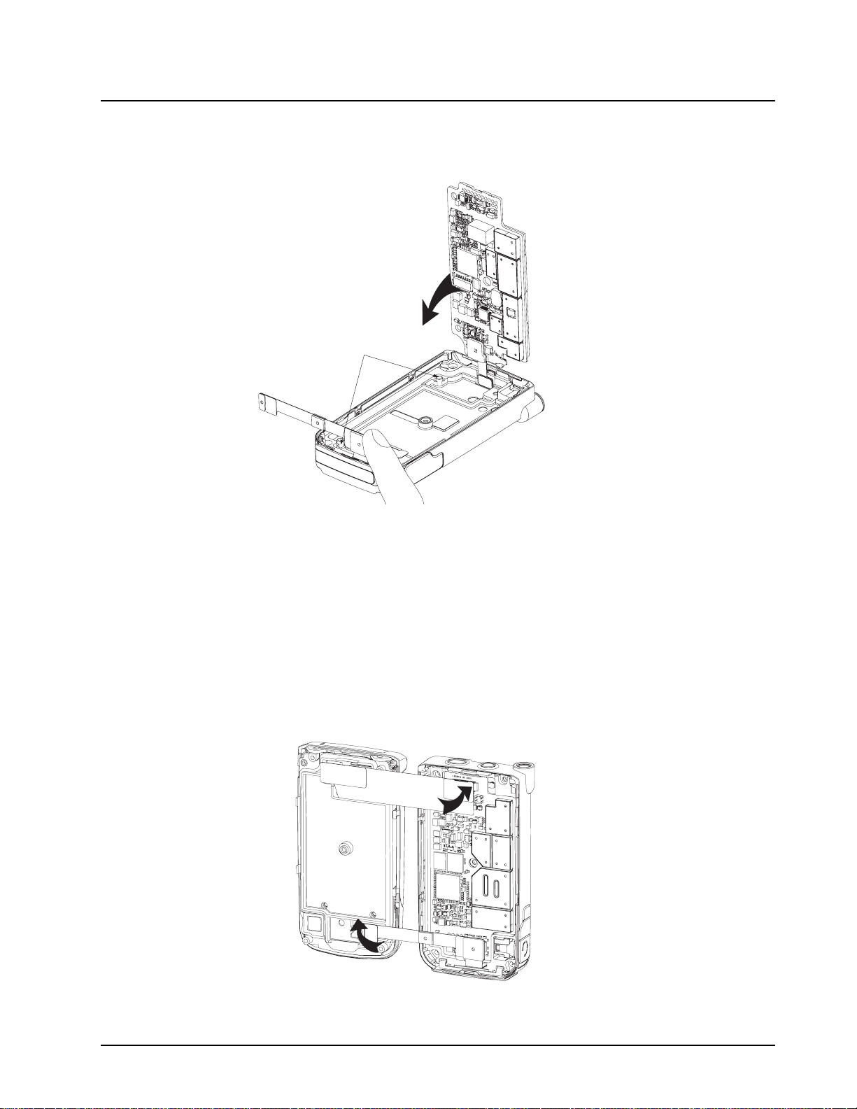
Disassembly/Reassembly Procedures: Radio Reassembly 8-29
18. While holding the CE-UCM Flex as shown in Figure 8-43 so as to clear the Main Board,
rotate the Main Board (29) towards the chassis and into position by aligning the board to the
two chassis alignment pins. Check to make sure the battery B-plus seal is not pinched.
Chassis alignment
feature
Figure 8-43. Holding CE-UCM Flex
19. Plug the CE-UCM Connector Flex (28) to the Main Board (29).
8.7.4 Assemble the Chassis Assembly to the Flip-Front Housing Assembly
To assemble the chassis sub assembly (C) and Flip-Front Housing Assembly (A+B):
1. Place the Flip-Front Housing Assembly and chassis assembly side by side with the chassis
on the right. Plug in the connector of the Keypad Backer Inner Jumper Flex (17) to the Main
Board (29) top side. Also plug in the connector on the CE-UCM Connector Flex (28) to the
UCM Board (10) located at the bottom of the Flip-Front Housing Assembly as shown in
Figure 8-44.
Figure 8-44. Reassemble Flexes
6871619L01-C September 10, 2008
Page 94

8-30 Disassembly/Reassembly Procedures: Servicing CID Bezel Only
2. Rotate the chassis assembly towards the Flip-Front Housing Assembly. Snap fit both
assemblies by pressing the 2 snaps on the PTT side and the 2 snaps on the opposite PTT
side. Ensure there is no bulging between the Front Housing and the Control Band (20) to
confirm that the 4 snaps are properly engaged.
3. With the back of the radio facing upward, assemble the 5 screws with a Torx T7 bit at
4.4 in-lbf.
3
1
5
2
4
Figure 8-45. Screws Reassemble Sequence
4. Reassemble the antenna to the chassis by turning it clockwise with hand.
5. Tongue in the battery to the bottom of the chassis and press it towards the casting until it
clicks.
6. Power on the radio by pressing the Power Button.
8.8 Servicing CID Bezel Only
8.8.1 Disassemble CID Bezel
Refer steps 2 to 5 of “8.6.4 Disassemble the Flip Assembly” on page 8-16 to disassemble the CID
Bezel Kit (1).
8.8.2 Reassemble CID Bezel
Prepare the Flip Sub-Assembly (3) surface as described in the first caution note of Section “8.7
Radio Reassembly” on page 8-17 then continue reassembling by following steps 3 to 6 of
“8.7.1 Reassemble the Flip Assembly” on page 8-18.
September 10, 2008 6871619L01-C
Page 95
Basic Troubleshooting: Power-Up Error Codes 9-1
Chapter 9 Basic Troubleshooting
This section of the manual contains troubleshooting charts and error codes that will help you to
isolate a problem. Level one and two troubleshooting will support only radio alignment,
programming, battery replacement, and knob replacement, and circuit board replacement.
Component-level service information can be found in the “ASTRO XTS 4000 Portable Radios
Detailed Service Manual,” Motorola publication number 68P71620L01.
9.1 Power-Up Error Codes
When the radio is turned on (power-up), the radio performs self-tests to determine if its basic
electronics and software are in working order. Problems detected during these tests are presented
as error codes on the radio’s display. For non-display radios, the problem will be presented at
power-up by a single, low-frequency tone. The radio should be sent to the depot if cycling power and
reprogramming the code plug do not solve the problem. The presence of an error should prompt the
user that a problem exists and that a service technician should be contacted.
Self-test errors are classified as either fatal or non-fatal. Fatal errors will inhibit user operation;
non-fatal errors will not. Use Table 9-1 to aid in understanding particular power-up error code
displays.
Table 9-1. Power-Up Error Code Displays
Error
Code
01/02 FLASH ROM Codeplug Checksum Non-Fatal Error Reprogram the codeplug
01/12 Security Partition Checksum Non-Fatal Error Send radio to depot
01/20 ABACUS Tune Failure Non-Fatal Error Turn the radio off, then on
01/22 Tuning Codeplug Checksum Non-Fatal Error Send radio to depot
01/81 Host ROM Checksum Fatal Error Send radio to depot
01/82 FLASH ROM Codeplug Checksum Fatal Error Reprogram the codeplug
01/88 External RAM Fatal Error — Note: Not a checksum failure Send radio to depot
01/90 General Hardware Failure Fatal Error Turn the radio off, then on
01/92 Security Partition Checksum Fatal Error Send radio to depot
01/93 FLASHport Authentication Code Failure Send radio to depot
01/98 Internal RAM Fail Fatal Error Send radio to depot
01/A2 Tuning Codeplug Checksum Fatal Error Send radio to depot
02/81 DSP ROM Checksum Fatal Error Send radio to depot
Description Corrective Action
02/88 DSP RAM Fatal Error – Note: Not a checksum failure Turn the radio off, then on
02/90 General DSP Hardware Failure (DSP startup message not
received correctly)
6871619L01-C September 10, 2008
Turn the radio off, then on
Page 96

9-2 Basic Troubleshooting: Operational Error Codes
Table 9-1. Power-Up Error Code Displays (Continued)
Error
Code
09/10 Secure Hardware Error Turn the radio off, then on
09/90 Secure Hardware Fatal Error Turn the radio off, then on
Note: If the corrective action does not fix the failure, send the radio to the depot.
Description Corrective Action
9.2 Operational Error Codes
During radio operation, the radio performs dynamic tests to determine if the radio is working
properly. Problems detected during these tests are presented as error codes on the radio’s display.
The presence of an error code should prompt a user that a problem exists and that a service
technician should be contacted. Use Table 9-2 to aid in understanding particular operational error
codes.
Table 9-2. Operational Error Code Displays
Error Code Description Corrective Action
FAIL 001 Synthesizer Out-of-Lock 1. Reprogram external codeplug
FAIL 002 Selected Mode/Zone Codeplug
Checksum Error
2. Send radio to depot
Reprogram external codeplug
9.3 Receiver Troubleshooting
Table 9-3 lists the possible causes of, and corrections for, receiver problems.
Table 9-3. Receiver Troubleshooting Chart
Symptom Possible Cause
Radio Dead; Display Does Not
Turn On
Radio Dead; Display
Turns On
No Receive Audio, or Receiver
Does Not Unmute
1. Dead Battery Replace with charged battery
2. Blown Fuse Send radio to depot
3. On/Off Switch
4. Regulators
Main Board Send radio to depot
Programming 1. Does the transmitted signal match the receiver
Correction or Test
(Measurements at Room Temperature)
configuration (PL, DPL, etc.)?
2. With the monitor function enabled, can the
radio be unmuted?
September 10, 2008 6871619L01-C
Page 97

Basic Troubleshooting: Transmitter Troubleshooting 9-3
Table 9-3. Receiver Troubleshooting Chart (Continued)
Symptom Possible Cause
Audio Distorted or Not Loud
Enough
RF Sensitivity Poor 1. Synthesizer Not On
Radio Will Not Turn Off Main Board Send radio to depot
Synthesizer Not On
Frequency
Frequency
2. Antenna Switch/
Connector
3. Receiver FrontEnd Tuning
9.4 Transmitter Troubleshooting
Table 9-4 lists the possible causes of, and corrections for, transmitter problems.
Table 9-4. Transmitter Troubleshooting Chart
Correction or Test
(Measurements at Room Temperature)
Check synthesizer frequency by measuring the
transmitter frequency; realign if off by more than
±1000 Hz
Check synthesizer frequency by measuring the
transmitter frequency; realign if off by more than
±1000 Hz
Send radio to depot
Check RF front-end tuning for optimum sensitivity
using the tuner
Symptom Possible Cause
No RF Power Out 1. TX Power Level or Frequency Check TX power level and frequency
2. No Injection To Power
Amplifier
3. Antenna Switch/Connector
No Modulation;
Distorted Modulation
Bad Microphone Sensitivity 1. Check Deviation and
No/Low signaling
(PL, DPL, MDC)
Cannot Set Deviation
Balance
1. Programming Check deviation and compensation
2. Main Board Send radio to depot
Compensation
2. Microphone Send radio to depot
1. Programming Check programming
2. Main Board Send radio to depot
Main Board Send radio to depot
Correction or Test (Measurements
Taken at Room Temperature)
programming (from tuner)
Send radio to depot
settings using the tuner
Realign if necessary
6871619L01-C September 10, 2008
Page 98

9-4 Basic Troubleshooting: Encryption Troubleshooting
9.5 Encryption Troubleshooting
Table 9-5 lists the possible causes of, and corrections for, encryption problems.
Table 9-5. Encryption Troubleshooting Chart
Symptom Possible Cause Corrective Action
No “KEYLOAD” on Radio Display When
Keyloading Cable is Attached to the Radio
Side Connector
Keyloader Displays “FAIL” 1. Wrong Keyloader Type Use correct keyloader
1. Defective Keyload Cable Send radio to depot
2. Defective Radio
type. Refer to Keyloader
User Guide for more
information
2. Bad Keyloader Try another keyloader
3. Defective Radio Send radio to depot
September 10, 2008 6871619L01-C
Page 99

Exploded Views and Parts Lists 10-1
Chapter 10 Exploded Views and Parts Lists
This chapter contains exploded views and associated parts lists for the ASTRO XTS 4000 digital portable radios. The following table lists the various
exploded views and parts lists for the XTS 4000 radios:
Table 10-1. XTS 4000 Exploded Views and Parts Lists
View Page
Exploded View and Parts List – Main Assemblies 10-2
Exploded View and Parts List – Flip-Front Housing
Assemblies
Exploded View and Parts List – Chassis Assembly 10-4
Parts List – Service Kit 10-5
10-3
6871619L01-C September 10, 2008
Page 100

10-2 Exploded Views and Parts Lists: Exploded View and Parts List – Main Assemblies
10.1 Exploded View and Parts List – Main Assemblies
D
Table 10-2. Parts List – Main Assemblies
Item No. Motorola Part Number Description
A. Flip Assembly
B. Front Housing Assembly
C. Chassis Assembly
D. Antenna Assembly
NAD6582_ (8571814L02)
or NAD6581_ (8571814L04)
or NAD6583_ (8571814L01)
or NAE6552_ (8571814L05)
E. Battery Assembly
Battery Pack See Section “A.2 Batteries and Battery Accessories” on page A-1 in “Appendix A: Accessories”
Antenna 136 – 151 MHz (Yellow coded)
Antenna 146 – 162 MHz (Black coded)
Antenna 162 – 174 MHz (Blue coded)
Antenna 380 – 470 MHz (Red coded)
E
A
C
B
Figure 10-1. Exploded View – Main Assemblies
September 10, 2008 6871619L01-C
 Loading...