

Page 1
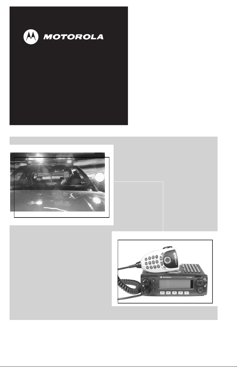
ASTRO
®
XTL™ 2500
Digital Mobile Radio
M5 Control Head
User's Guide
Page 2

Page 3
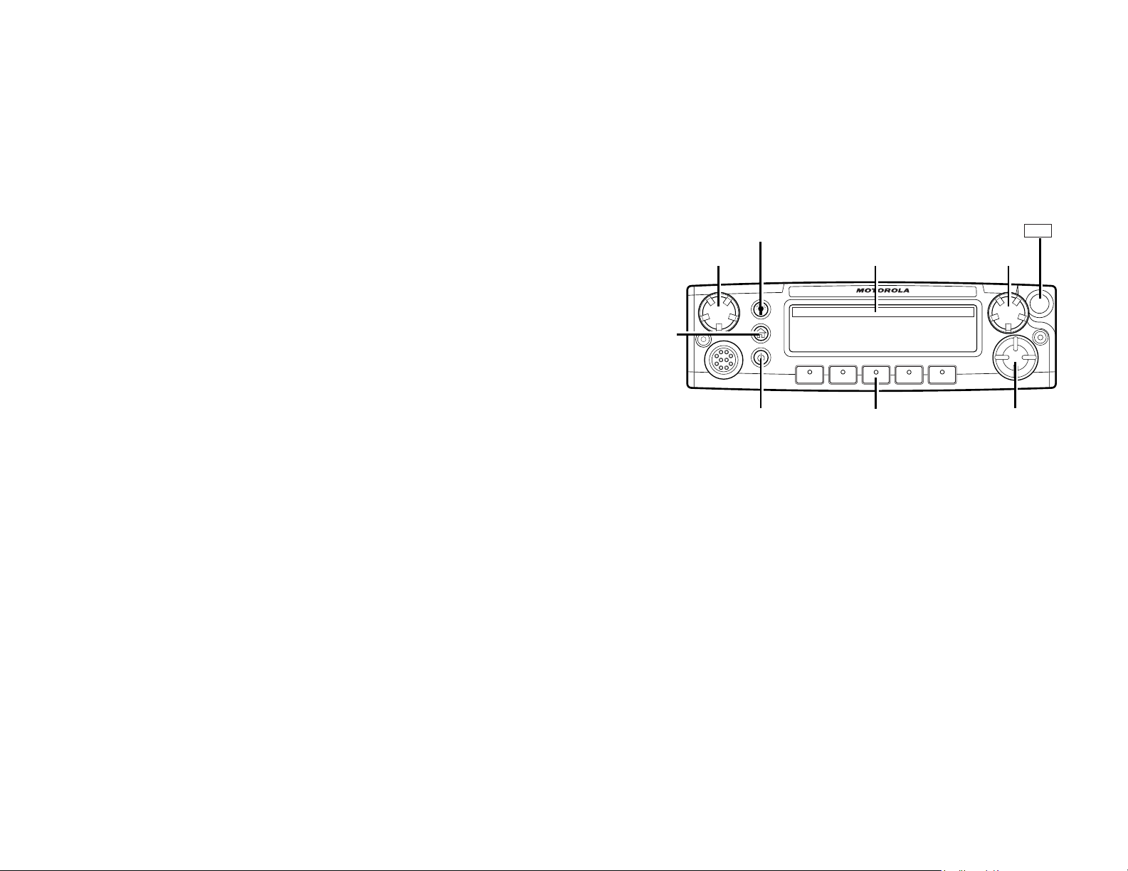
M5 Control Head Foldout Page
M5 Control Head
HOME
VOLUME
KNOB
DIM
BUTTON
POWER
ON/OFF
INDICATORS
SOFT MENU
KEYS
EMERGENCY
Emer
MODE
KNOB
XTL 2500
NAVIGATION
KEYS
ASTRO XTL 5000 Digital Mobile Radio with O5 Control Head i
Page 4

Page 5

This declaration is applicable to your radio only if your radio is labeled
with the FCC logo shown below.
DECLARATION OF CONFORMITY
Per FCC CFR 47 Part 2 Section 2.1077(a)
Responsible Party
Name: Motorola, Inc.
Address: 8000 West Sunrise Boulevard
Plantation, FL 33322 USA
Phone Number: 1-888-567-7347
Hereby declares that the product:
Model Name: XTL 2500
conforms to the following regulations:
FCC Part 15, subpart B, section 15.107(a), 15.107(d) and section 15.109(a)
Class B Digital Device
As a personal computer peripheral, this device complies with Part 15 of the FCC
Rules. Operation is subject to the following two conditions:
1. this device may not cause harmful interference, and
2. this device must accept any interference received, including interference that
may cause undesired operation.
Note: This equipment has been tested and found to comply with the limits for a
Class B digital device, pursuant to part 15 of the FCC Rules. These limits are
designed to provide reasonable protection against harmful interference in a
residential installation. This equipment generates, uses and can radiate radio
frequency energy and, if not installed and used in accordance with the
instructions, may cause harmful interference to radio communications.
However, there is no guarantee that interference will not occur in a particular
installation.
If this equipment does cause harmful interference to radio or television reception,
which can be determined by turning the equipment off and on, the user is
encouraged to try to correct the interference by one or more of the following
measures:
• Reorient or relocate the receiving antenna.
• Increase the separation between the equipment and receiver.
• Connect the equipment into an outlet on a circuit different from that to which
the receiver is connected.
• Consult the dealer or an experienced radio/TV technician for help.
ASTRO XTL 2500 Digital Mobile Radio with M5 Control Head ii
Page 6

Product Safety and RF Exposure Compliance
Before using this product, read the operating instructions for safe
!
usage contained in the Product Safety and RF Exposure booklet
Caution
enclosed with your radio.
ATTENTION!
This radio is restricted to occupational use only to satisfy FCC RF energy
exposure requirements. Before using this product, read the RF energy
awareness information and operating instructions in the Product Safety and RF
Exposure booklet enclosed with your radio (Motorola Publication part number
6881095C99) to ensure compliance with RF energy exposure limits.
Computer Software Copyrights
The Motorola products described in this manual may include copyrighted Motorola
computer programs stored in semiconductor memories or other media. Laws in the
United States and other countries preserve for Motorola certain exclusive rights for
copyrighted computer programs, including, but not limited to, the exclusive right to copy
or reproduce in any form the copyrighted computer program. Accordingly, any
copyrighted Motorola computer programs contained in the Motorola products described
in this manual may not be copied, reproduced, modified, reverse-engineered, or
distributed in any manner without the express written permission of Motorola.
Furthermore, the purchase of Motorola products shall not be deemed to grant either
directly or by implication, estoppel, or otherwise, any license under the copyrights,
patents or patent applications of Motorola, except for the normal non-exclusive license
to use that arises by operation of law in the sale of a product.
Documentation Copyrights
No duplication or distribution of this document or any portion thereof shall take place
without the express written permission of Motorola. No part of this manual may be
reproduced, distributed, or transmitted in any form or by any means, electronic or
mechanical, for any purpose without the express written permission of Motorola.
Disclaimer
The information in this document is carefully examined, and is believed to be entirely
reliable. However, no responsibility is assumed for inaccuracies. Furthermore,
Motorola reserves the right to make changes to any products herein to improve
readability, function, or design. Motorola does not assume any liability arising out of the
applications or use of any product or circuit described herein; nor does it cover any
license under its patent rights, nor the rights of others.
MOTOROLA, the Stylized M Logo, ASTRO, SmartZone and FLASHport are registered
in the U.S. Patent & Trademark Office. All other product or service names are the
property of their respective owners. P25 radios contain technology patented by Digital
Voice Systems, Inc.
© Motorola, Inc. 2005. Printed in the U.S.A. 4/05.
iii
Page 7

Notations Used in This Manual
Throughout the text in this publication, you will notice the use of WARNINGS,
CAUTIONS, and Notes. These notations are used to emphasize that safety
hazards exist, and care that must be taken or observed.
WARNIN G
!
CAUTION
!
Note: Note: An operational procedure, practice, or other condition,
The following special notations identify certain items:
Example Description
Light button or
PHONE
WARNING: An operational procedure, practice, or other
condition, which might result in injury or death if not carefully
observed.
CAUTION: An operational procedure, practice, or other
condition, which might result in damage to the equipment if not
carefully observed.
which is essential to emphasize.
>
Buttons and keys are shown in bold print or as a key
symbol.
Menu items (softkeys) are similar to the way they
appear on the radio’s display.
ASTRO XTL 2500 Digital Mobile Radio with M5 Control Head iv
Page 8

Notes
v
Page 9

Contents
M5 Control Head Foldout Page . . . . . . . . . . . . . . . . . . i
Declaration of Conformity .................................................................. ii
Computer Software Copyrights .........................................................iii
Documentation Copyrights ................................................................iii
Disclaimer .........................................................................................iii
Notations Used in This Manual ........................................................ iv
Introduction . . . . . . . . . . . . . . . . . . . . . . . . . . . . . . . . . . 1
Using Your Radio: The Basics .......................................................... 1
Getting Started .................................................................................. 2
Identifying Your Radio ....................................................................... 4
M5 Control Head ........................................................................ 4
Operating Your Control Head ............................................................ 5
Turning On the Radio ........................................................................ 5
Setting the Volume ..................................................................... 6
Adjusting the Display Brightness ................................................ 6
Using the navigation keys ........................................................... 6
Keypad Microphone Option ........................................................ 6
Trunked Modes or Conventional Channels ................................ 7
Field Programming ..................................................................... 7
Display Status ................................................................................... 8
Feature Control ................................................................................. 8
Alert Tones ........................................................................................ 8
Basic Operating Procedures . . . . . . . . . . . . . . . . . . . 11
Basic Functions ............................................................................... 11
Selecting the Zone or Mode ............................................................ 12
Selecting or Changing the Zone ............................................... 12
Selecting or Changing a Mode in the Current Zone ................. 13
Selecting or Changing to a Mode Not in the Current Zone ....... 13
Selecting the Home Mode ............................................................... 14
Transmitting (Conventional Modes Only) ........................................ 15
Transmitting (Trunked Modes Only) ................................................ 15
Selecting the Transmit Power Level ................................................ 16
Monitoring Conventional Mode Activity ........................................... 16
Adjusting the Squelch Level ............................................................ 17
General Radio Features . . . . . . . . . . . . . . . . . . . . . . . 18
Often-Used Features ....................................................................... 18
Emergency Call and Alarm ............................................................. 19
ASTRO XTL 2500 Digital Mobile Radio with M5 Control Head vi
Page 10

Emergency Call .........................................................................19
Initiating an Emergency Alarm ..................................................20
Initiating an Emergency Call .....................................................20
Initiating an Emergency Call and Alarm ....................................21
Initiating a Silent Emergency Alarm ..........................................22
Special Considerations for Emergencies ..................................22
Scan Operation ................................................................................23
Turning On Scan .......................................................................24
Turning Scan On While Disregarding the Squelch Code
(Conventional Modes Only) ...................................................25
Viewing a Scan List ...................................................................26
Transmitting While Scan Is On .................................................27
Temporarily Deleting a Nuisance Mode with Scan On ..............28
Restoring a Nuisance Mode ......................................................28
Changing Mode Priorities While Scan Is On .............................29
Restoring Mode Priorities in a Scan List ...................................29
Programming a Scan List ..........................................................30
Hang Up Box (HUB) ..................................................................32
Optional External Alarms (Horn and Lights) ....................................32
Activating the External Alarm(s) ................................................32
Changing the Selected Alarms .................................................33
Receiving a Call While Alarms Are Turned On .........................34
Time-Out Timer ................................................................................35
Push-To-Talk Identification (PTT-ID) ................................................35
Telephone Interconnect List (Conventional and Trunking) ..............36
Answering a Phone Call ............................................................36
Initiating a Telephone Call from the List ....................................37
Unlimited Telephone Interconnect ...................................................38
Calling a Phone Number Not in the List ....................................38
Storing a Number in the List .....................................................39
Editing a Name in the List ........................................................40
Call Alert Page (Conventional and Trunking— Digital Modes Only) 43
Sending a Call Alert Page .........................................................44
Conventional Radio Features . . . . . . . . . . . . . . . . . . 47
Features Used in Conventional Operation ......................................47
Status Calls (Digital Modes Only) ....................................................48
Sending a Status Call ...............................................................48
Sending a Direct-Entry Keyboard (DEK) Status .......................50
Smart PTT .......................................................................................51
vii
Page 11

Conventional Talkgroup Calls ......................................................... 51
Digital Modes Only ................................................................... 51
Selecting a Conventional Talkgroup ......................................... 52
Conventional Talkaround ................................................................ 53
Talk Direct (Mobile-To-Mobile) ................................................. 53
Selective Calls (Digital Modes Only) ............................................... 53
Answering a Selective Call ....................................................... 54
Initiating a Selective Call .......................................................... 55
Viewing Your Unit ID Number ................................................... 57
Storing a Unit ID Number in the List ......................................... 58
Editing a Name in the List ......................................................... 59
Trunking Operation . . . . . . . . . . . . . . . . . . . . . . . . . . . 61
Features Used on Trunking Systems .............................................. 61
Enhanced Private Conversation (Digital Modes Only) .................... 62
Answering an Enhanced Private Conversation Call ................. 62
Initiating an Enhanced Private Conversation Call .................... 63
Failsoft ............................................................................................. 65
Dynamic Regrouping (Digital Modes Only) ..................................... 66
Receiving a Dynamic Regrouping ID Assignment ................... 66
Selecting Enable and Disable (Digital Modes Only) ................. 67
Requesting a Dynamic Regrouping
(Digital Modes Only) .............................................................. 67
SmartZone ...................................................................................... 68
Site-Button Operation ............................................................... 68
Locking onto a Site ................................................................... 69
Site Trunking ............................................................................ 69
Out-of-Range Indication .................................................................. 70
Trunked Announcement .................................................................. 71
Initiating an Announcement ...................................................... 71
Secure Operation . . . . . . . . . . . . . . . . . . . . . . . . . . . . 73
Features Available on Secure XTL 2500 ........................................ 73
Receiving a Private Message ......................................................... 74
Transmitting a Private Message ...................................................... 74
System Considerations ................................................................... 75
Loss Indication ................................................................................ 75
Selecting an Encryption Key (Conventional Only) .......................... 76
Selecting an Encryption Index (Conventional Only) ........................ 78
ASTRO XTL 2500 Digital Mobile Radio with M5 Control Head viii
Page 12

Troubleshooting . . . . . . . . . . . . . . . . . . . . . . . . . . . . . 79
Accessories. . . . . . . . . . . . . . . . . . . . . . . . . . . . . . . . . 81
Antennas .........................................................................................81
Bull Horns for Siren and Public Address .........................................83
Cables .............................................................................................83
Microphones ....................................................................................84
Miscellaneous ..................................................................................84
Remote Mounting Kits .....................................................................85
Speakers ..........................................................................................85
Trunnion Kits ....................................................................................85
Appendix: Maritime Radio Use in the VHF Frequency
Range. . . . . . . . . . . . . . . . . . . . . . . . . . . . . . . . . . . . . . 86
Special Channel Assignments .........................................................86
Emergency Channel .................................................................86
Non-Commercial Call Channel .................................................87
Operating Frequency Requirements ...............................................87
Glossary . . . . . . . . . . . . . . . . . . . . . . . . . . . . . . . . . . . 91
Commercial Warranty and Service . . . . . . . . . . . . . . 95
Limited Warranty .............................................................................95
Service .............................................................................................99
Index . . . . . . . . . . . . . . . . . . . . . . . . . . . . . . . . . . . . . 101
ix
Page 13

Introduction
Using Your Radio: The Basics
This chapter gives you the basic knowledge you need in order to use
your radio. The following topics are covered:
• Getting Started (page 2)
• Identifying Your Radio (page 4)
• Operating Your Control Head (page 5)
• Turning On the Radio (page 5)
• Setting the Volume (page 6)
• Adjusting the Display Brightness (page 6)
• Keypad Microphone Option (page 6)
• Display Status (page 8)
• Feature Control (page 8)
• Alert Tones (page 8)
ASTRO XTL 2500 Digital Mobile Radio with M5 Control Head 1
Page 14

Introduction
Getting Started
The ASTRO® XTL™ 2500 Digital Mobile Radio is among the most
sophisticated two-way radios available. It can operate in the following
frequency ranges:
VHF UHF 700/800 MHz
136-174 MHz 380-470 MHz 762-776 MHz
450-520 MHz 794-806 MHz
806-825 MHz
851-870 MHz
These channels provide maximum communications capability under
varying operating conditions.
One of the newest in a long line of quality Motorola products, the
ASTRO XTL 2500 Digital Mobile Radio provides improved voice
quality across more of your coverage area. The digital process called
embedded signaling intermixes system signaling information with
digital voice, resulting in improved system reliability and the capability
of supporting a multitude of advanced features. Such features add up
to better, more cost-effective two-way radio communications.
ASTRO digital technology is also helping to provide the solution to
improved spectral efficiency requiring only half as much bandwidth
per channel (12.5kHz) compared to analog technology (25/30kHz).
The net benefit to you is fewer users per channel or more users per
system.
The ASTRO XTL 2500 Digital Mobile radio can include an optional
RS-232 data port to interface with external devices, such as certain
fax machines and laptop computers. ASTRO XTL 2500 Digital Mobile
voice radios and data terminals can access the same channel without
interfering with each other.
2
Page 15

Introduction
Note: In this manual—
Analog mode refers to a mode that uses traditional, non-ASTROdigital signaling.
ASTRO mode refers to a mode that uses ASTRO digital signaling.
Your ASTRO XTL 2500 Digital Mobile Radio utilizes Motorola’s
revolutionary FLASHport™ technology. This allows your radio’s
capabilities to be flexible, because FLASHport makes it possible to
add software that drives these capabilities both at the time of
purchase and later on. Similar to how a computer can be loaded with
different software, your radio’s features and capabilities can be
upgraded with software.
FLASHport allows you to add software to your radio as your needs
change and as technology advances, making your radio investment
go further.
FLASHport is the future of radio communications, and it’s yet another
example of Motorola’s commitment to your satisfaction.
ASTRO XTL 2500 Digital Mobile Radio with M5 Control Head 3
Page 16

Introduction
Identifying Your Radio
The ASTRO XTL 2500 Digital Mobile Radio has two major
components: the radio unit installed in your vehicle and the control
head that is used to activate various radio features. Keep the foldout
page opened for reference as you read this manual. Your radio has
the following control head:
M5 Control Head
The M5 has the rotary Mode and Volume knobs, 5 programmable
menu buttons, a menu navigation button, and a 3-line, 14-character,
fully bitmapped display (page i).
Note: A "CH MISMATCH" error upon turning on your radio, means
that either the Control Head has been connected to a legacy
transceiver, or vice versa.
4
Page 17

Introduction
Operating Your Control Head
Your advanced control head is designed for ease of use and flexibility
of feature control. Before operating the radio, familiarize yourself with
the various controls, indicators, and alert tones. Refer to the foldout
diagrams in the front and back of this manual for your particular
control head.
Turning On the Radio
Basic operation is the same for all radio control heads..
Do the following:
• Turn the radio on with a short press of the power button in
the lower left corner of the control unit.
After a short time, the red, green and yellow LED’s light up,
indicating that the radio is powering up.
The display then shows XTL 2500.
When the radio is fully powered on, the Zone and Channel text and
menu items is displayed. The backlight will turn on to the last
selected color and dim level.
Note: Pressing the power button before the LED’s light up will be
ignored.
Pressing the power button anytime after the LED’s light up
will TURN OFF the radio.
Note: If FAIL ##/## appears in the display, the radio will not
function until the condition has been corrected.
If ERROR ##/## appears, some non-critical data has been
changed. If either of these displays appear, if the display
goes blank, or if the unit appears to be locked up, refer to the
“Troubleshooting” section.
ASTRO XTL 2500 Digital Mobile Radio with M5 Control Head 5
Page 18

Introduction
Setting the Volume
Rotate the Vol u me knob clockwise to increase the volume and
counterclockwise to decrease the volume.
Adjusting the Display Brightness
Press the dimmer button (DIM) to change the display brightness
to one of four levels:
• Off to high
• High to medium
• Medium to low
•Low to off
In Off, both the display and backlight are off (used for
surveillance operations).
Using the navigation keys
When accessing a feature on the radio, use the left or right
toggles on the navigation key to access further options within
the menu.
If you cannot locate a menu item, it may not be programmed, or
it may not apply to the radio's current mode setting.
Keypad Microphone Option
If your radio is equipped with a keypad microphone, you can
perform the same navigation functions from that keypad that are
available on the Control Head. The keypad also enables you to
use certain capabilities within features such as telephone
interconnect and Selective Call. These capabiliites are
described in detail within the appropriate sections of this
manual.
Note: The checkmark and X buttons on the keypad microphone
are for future use and not currently used by the radio.
6
Page 19

Introduction
Trunked Modes or Conventional Channels
Depending on how your radio is programmed, you can select
conventional channels or trunked talkgroup. Conventional channels
consist of a transmit and receive frequency pair, an associated
squelch code pair, and a time-out timer value. See “Conventional
Radio Features” on page 47.
Trunked modes consist of the system/announcement group/talkgroup
combination and a time-out timer value. See “Trunking Operation” on
page 61.
Field Programming
Other radio features may be slaved to the selected mode by field
programming. This mode slaving means that the radio is
preprogrammed to automatically give you the proper operation for
each mode you select.
You may use the control head to program your own mode names.
The names you assign are clearly shown in the alphanumeric display.
You can see all the key operating information, including the mode
selected or being scanned, and the on/off status of various features.
The operating conditions are shown either by the display or by visual/
audio indicators, or by both.
ASTRO XTL 2500 Digital Mobile Radio with M5 Control Head 7
Page 20

Introduction
Display Status
The control head display indicates your selected mode, or the
currently active receive mode when scan is on.
Feature Control
You can turn the various radio features on or off, change modes, and
adjust the volume.
To exit a feature, such as phone, press the HOME button.
Alert Tones
Tone Type Name Description
Two highpitched tones
Four highpitched tones
every five
seconds
Single, highpitched tone
Four highpitched tones
Sound similar
to a telephone
busy signal
Private
Conversation™
Call Alert Indicate that a Call Alert page has been
Central
Acknowledge
Mobile Unit
Acknowledge
System Busy Indicates, when you press the
Indicate that a private call has been
received.
received.
Indicates that a Call Alert, emergency
alarm, reprogram request, or status/
message transmission has been
received by the system’s central
controller.
Indicate that a Call Alert page has been
received by the intended unit, or the
emergency alarm, reprogram request, or
status/message transmission has been
acknowledged by the intended
dispatcher.
microphone push-to-talk (PTT) button,
that you cannot transmit because all
system radio channels are in use.
Release the PTT button and wait for call
back.
8
Page 21

Tone Type Name Description
Introduction
A series of
two short,
high-pitched
tones
A series of
two short,
high-pitched
tones (same
as automatic
call back)
Continuous,
low-pitched
tone
Single, highpitched tone
every nine
seconds
Automatic Call
Back
Tal k P e r m i t
(optional)
Talk-Prohibit/
Out-of-Range
Failsoft In an unmuted receive condition,
Indicate that a channel is now available
for your previously requested
transmission.
Indicate, when you press the
microphone PTT button, that the system
is accepting your transmission.
Indicates, when you press the
microphone PTT button, that either you
are out of the range of the trunked radio
system, or the system is out of service,
or the channel is busy with the Smart
PTT feature enabled.
indicates a trunked system central
controller failure. The radio reverts from
trunked operation to a system similar to
conventional radio repeater operation.
Other system users can be heard
sharing the channel.
Continuous,
low-pitched
tone
Brief lowpitched tone
ASTRO XTL 2500 Digital Mobile Radio with M5 Control Head 9
Illegal Mode Indicates that you have entered a mode
where normal system traffic will be
missed, or you are attempting something
which is not permitted. Examples
include: forgetting to exit the telephone
interconnect mode after a call ends (fleet
and subfleet calls cannot be received),
attempting to transmit on a receive-only
conventional mode, attempting to select
a dynamic mode where no dynamic ID
assignment has been made.
Time-Out Timer
Warning
Indicates that your present transmission
will soon be disabled.
Page 22

Introduction
Tone Type Name Description
Single, short,
high-pitched
tone
Single, lowpitched tone
Unique
chirping
sound
Valid Key Indicates that you pressed a valid key, or
you entered a feature configuration
state, or you are receiving or
transmitting in the clear mode on secure
models (with TX Clear Alert Tones
enabled).
Invalid Key Indicates that you tried to make an
invalid key press, or that an emergency
alarm, reprogram request, or status/
message was not acknowledged.
Dynamic
Reprogramming
Indicates that a dynamic ID is assigned.
10
Page 23

Basic Operating Procedures
Basic Functions
This chapter shows you how to access the radio’s basic functions and
includes the following topics:
• Selecting the Zone or Mode (page 12)
• Selecting the Home Mode (page 14)
• Transmitting (Conventional Modes Only) (page 15)
• Transmitting (Trunked Modes Only) (page 15)
• Selecting the Transmit Level (page 16)
• Monitoring Conventional Mode Activity (page 16)
• Adjusting the Squelch Level (page 17)
ASTRO XTL 2500 Digital Mobile Radio with M5 Control Head 11
Page 24

Basic Operating Procedures
Selecting the Zone or Mode
A zone is a grouping of modes. A mode is a group of characteristics
such as transmit/receive frequencies, Private-Line™ codes, radio
parameters, and an alphanumeric name.
Selecting or Changing the Zone
1 Press thebutton to scroll to the ZONE softkey.
2 Press the button below ZONE.
The display shows the current zone and mode.
3 Press the or until the desired zone is displayed.
4 Press the or PTT button to save the displayed
zone as the new home (default) zone.
The zone name stops flashing once it is saved.
5 Press the PTT button to begin transmitting on the
displayed zone.
12
Page 25

Basic Operating Procedures
Selecting or Changing a Mode in the Current Zone
To access a mode in the current zone, do the following:
• Rotate the Mode knob until the display shows the desired
mode name.
OR
1 Press and hold to scroll to the CHAN softkey.
2 Press the below CHAN.
The display shows the current zone and mode.
3 Rotate the Mode Knob until the desired channel in the
current zone is displayed.
4 Press the or PTT button to save the displayed
channel as the new home (default) channel.
The channel name stops flashing once it is saved.
5 Press the PTT button to begin transmitting on the
displayed zone and mode.
Selecting or Changing to a Mode Not in the Current
Zone
1 To access a mode that is not in the current zone, press the
Zone up
containing the mode.
Note: The Zone up
2 Do one of the following:
• Select a desired zone (page 12).
• Select a desired mode in the current zone (page 13).
ASTRO XTL 2500 Digital Mobile Radio with M5 Control Head 13
button or Zone down button to move to the zone
and Zone down buttons are optional
buttons included with the radio when zone/mode is ordered.
Page 26

Basic Operating Procedures
Selecting the Home Mode
This feature must first be enabled by a qualified radio
technician.
Press the HOME button to select the home mode contained
within the home zone, from any other zone and mode in the
radio.
14
Page 27

Basic Operating Procedures
Transmitting (Conventional Modes Only)
1 Lift the microphone off-hook, and listen for activity on that mode.
2 If you hear no activity, press and hold the microphone PTT
button.
Transmitting (Trunked Modes Only)
1 Lift the microphone off-hook, and press the microphone PTT
button.
2 Do one of the following:
• If you hear three quick tones, or if you hear no tone and the
red XMIT (transmit) indicator lights steadily, then proceed
with your message.
Release the PTT button to receive.
OR
• If you hear a continuous low-pitched tone, you are out of the
system's range.
The display area may indicate “OUT OF RANGE“ in the text
display area.
The red XMIT indicator may flash several times as the radio
tries to access the system.
Release the PTT button and try again when the vehicle is
driven within range of the system.
ASTRO XTL 2500 Digital Mobile Radio with M5 Control Head 15
Page 28

Basic Operating Procedures
Selecting the Transmit Power Level
The PWR softkey lets you select (toggle) the transmit power level.
Press the PWR softkey.
The display momentarily shows POWER LOW or POWER HIGH to
indicate the transmit power level selected.
Monitoring Conventional Mode Activity
This feature allows you to monitor channel traffic on conventional
channels by defeating the coded squelch. This feature must first be
enabled by a qualified radio technician or system administrator.
Do one of the following:
Take the microphone off hook.
(This is the same as monitor on. You hear all channel traffic.)
OR
1 Make sure you are in Home mode where the default zone and
mode are being displayed (page 14).
2 Press the or button to scroll to the MON softkey.
3 Pressing MON softkey momentarily toggles between MONITOR ON
and MONITOR OFF. MONITOR ON shown on the display indicates
that the radio is monitoring.
4 Pressing MON softkey again turns monitor off and you don’t hear
all channel traffic.
16
Page 29

Basic Operating Procedures
Adjusting the Squelch Level
Your radio’s ability to transmit or receive signals varies as you move
away from or close to your base station. You can adjust your radio’s
squelch to improve its ability to receive transmissions.
Do the following:
1 Press the or button to scroll to the MON softkey.
• Press and hold the button below MON.
The display shows SQUELCH XX, where XX is a squelch level
setting of 0 to 15.
2 Press to return to the selected channel.
ASTRO XTL 2500 Digital Mobile Radio with M5 Control Head 17
Page 30

General Radio Features
Often-Used Features
This chapter shows you how to access the most frequently used
features. The following topics are covered:
• Emergency Call and Alarm (page 19)
• Scan Operation (page 23)
• Optional External Alarms (Horn and Lights) (page 32)
• Time-Out Timer (page 35)
• Push-To-Talk Identification (PTT-ID) (page 35)
• Telephone Interconnect List (Conventional and Trunking)
(page 36)
• Unlimited Telephone Interconnect (page 38)
• Call Alert Page (Conventional and Trunking—Digital Modes
Only)
(page 43)
18
Page 31

General Radio Features
Emergency Call and Alarm
The emergency call and alarm features allow you to have priority
channel access and/or send an emergency data transmission to the
dispatcher in an emergency situation.
The desired type of emergency feature—alarm, call, call and alarm,
or silent alarm—can be preprogrammed by a qualified radio
technician.
The radio must be turned on to activate any emergency feature.
Emergency Call
Emergency call gives you priority access to a voice channel for all
subsequent transmissions after you press the emergency button. The
level of priority access is determined by the system manager.
SmartZone Emergency Call Receive Operation
A radio configured for SmartZone
RECEIVED whenever it receives an emergency call. The display
alternates with the selected-mode display as long as the radio is
unmuted to the emergency call.
®
operation displays EMER
ASTRO XTL 2500 Digital Mobile Radio with M5 Control Head 19
Page 32

General Radio Features
Initiating an Emergency Alarm
The emergency alarm feature sends a data transmission to alert the
dispatcher of your emergency condition and identify your unit ID.
Press the emergency button.
A tone sounds and the display alternates EMERGENCY with the
current zone/channel.
For trunking modes, a high-pitched tone indicates that the
alarm has been received by the trunked system’s central
controller.
A dispatcher acknowledgment ACK RECEIVED display follows.
The radio automatically returns to normal operation. No further
action is required.
Initiating an Emergency Call
1 Press the emergency button.
A tone sounds and the display alternates EMERGENCY with the
current zone/channel.
2 Press the PTT button and announce your emergency.
3 After completing the emergency call, press and hold the
emergency button until a tone sounds.
The alternating EMERGENCY display disappears, and the radio
returns to normal operation.
20
Page 33

General Radio Features
Initiating an Emergency Call and Alarm
If the radio has both emergency call and alarm features, it
automatically proceeds to the call mode after the alarm is
acknowledged.
1 Press the emergency button to activate the emergency call/
alarm feature.
The display begins alternating EMERGENCY with the current
zone/channel.
For trunking modes, a high-pitched tone sounds, indicating
that the alarm has been received by the trunked system’s
central controller.
A dispatcher acknowledgment (four high-pitched tones) follows,
accompanied by an ACK RCVD display.
2 Press the PTT button and announce your emergency.
3 To exit from the emergency state altogether, press and hold the
emergency button until a tone sounds.
The alternating EMERGENCY display disappears, and the radio
returns to normal operation.
Note: Turning the radio off also cancels the emergency state.
ASTRO XTL 2500 Digital Mobile Radio with M5 Control Head 21
Page 34

General Radio Features
Initiating a Silent Emergency Alarm
1 Press the emergency button to activate the silent alarm feature.
During a silent emergency alarm, there are no display changes,
and the receiver audio mutes so that no indication is given that
an emergency alarm has been sent.
2 To exit the silent alarm mode, press and hold the emergency
button until a tone sounds.
Note: If silent emergency alarm is used with emergency call,
pressing the PTT button exits the silent mode and initiates
the emergency call.
Special Considerations for Emergencies
• If you press the emergency button while in a mode that has no
emergency capability, a low-pitched tone sounds.
• If the unit is out of the range of the system and/or the emergency
alarm is not acknowledged, a tone sounds and the display shows
NO ACKNOWLEDGE.
• If you press the emergency button, then change to a mode that
has no emergency capability, a NO EMERGENCY display alternates
with the mode name display, and a continuous low-pitched tone
sounds until a valid emergency mode is selected or until the
emergency is cancelled.
• When an emergency is active, changing to another mode where
emergency is enabled (trunked or conventional) causes an
emergency alarm and/or emergency call to be active on the new
mode.
22
Page 35

General Radio Features
Scan Operation
The scan feature allows you to monitor activity on different
conventional or trunked modes by scanning a scan list of modes. The
modes to be scanned in a scan list are programmed by a qualified
radio technician. You can select the modes to be scanned in a scan
list if operator-selectable scan is enabled.
There are three types of scan lists available:
• Conventional—Comprises up to 15 different conventional-only
modes
• Trunked Priority Monitor—Comprises up to 15 modes that are all
from the same trunked system
• Talkgroup Scan—Comprises up to 10 combined conventional
modes and modes from one trunking system
The radio supports both priority and non-priority scanning. With
priority scanning enabled, a scan list can have one mode assigned as
the first-priority mode and a second as the second-priority mode.
The XTL 2500 Digital Mobile Radio supports automatic scanning
(autoscan), which can be programmed into the radio by a qualified
radio technician. With this feature, the radio begins scanning
whenever you select a mode to which a scan list is assigned.
Note: You cannot turn scan off on a mode that has autoscan
enabled.
If multiple scan types are enabled in the radio, the type of scan that is
activated depends on the personality of the mode selected when the
SCAN softkey is pressed. For all types of scan, the selected mode is,
by default, a member of its own scan list.
Scan lists stay in memory when you turn scan off, turn the radio off, or
disconnect the radio from the battery.
ASTRO XTL 2500 Digital Mobile Radio with M5 Control Head 23
Page 36

General Radio Features
Turning On Scan
Do the following:
1 Press the button to scroll to the SCAN softkey.
2 Press the button below SCAN.
The Scan indicator lights and a list of modes is scanned
for activity. The text display area will indicate SCAN ON
if scan is currently enabled or SCAN OFF if scan is just
been turned off.
When a scanned mode becomes active, the display
changes to show the active mode name, the appropriate
priority indicator lights, and the radio unmutes.
The radio will not begin scanning again for a
predetermined hang time after the call ends, giving you
time to respond. The hang time is typically three
seconds (by default), but can be changed by a qualified
radio technician.
Note: A lit N PRI (non-priority) indicator means that the active
mode is a non-priority member of the scan list (for all scan
types).
A solidly-lit PRI (priority) indicator means that the active
mode is the priority 2 member of the scan list (Trunking
Priority Monitor and Conventional scan types only).
A blinking PRI indicator means that the active mode is the
priority 1 member of the scan list (Trunking Priority Monitor
and Conventional scan types only).
24
Page 37

General Radio Features
Turning Scan On While Disregarding the Squelch
Code
(Conventional Modes Only)
Do the following:
1 Press the button to scroll to the MON softkey.
2 Press the button below MON.
3 The brief MONITOR ON display indicates that the radio is
disregarding the squelch code.
Note: While scanning for activity, you can still receive fleetwide,
system-wide, dynamic regrouping, incoming telephone
interconnect and Private Conversation/Call Alert calls.
Respond to these types of calls as you would normally on
the selected mode. However, when scanning different
modes while in talkgroup scan, incoming Private
Conversation/Call Alert calls may be missed.
ASTRO XTL 2500 Digital Mobile Radio with M5 Control Head 25
Page 38

General Radio Features
Viewing a Scan List
1 Press and hold the SCAN softkey until the Scan indicator blinks
and a beep is heard.
The radio suspends scanning while a scan list is being
reviewed.
2 Press the button to scroll to the VIEW softkey.
3 Press the button below VIEW.
4 Press the button to scroll to the SCAN softkey.
5 Press the button below SCAN. The radio suspends
scanning while a scan list is being reviewed.
6 Press the or button to scroll through the preprogrammed
scan list.
7 Those modes that are in the scan list are indicated by N PRI,
PRI or blinking PRI indicator (indicating the mode’s assigned
priority as previously described).
8 Press RCL softkey to review only modes that are already in the
scan list.
Press the HOME button momentarily to exit the scan list and
resume scanning.
26
Page 39

General Radio Features
Transmitting While Scan Is On
Radio Programmed for Talkback Scan
Press the microphone PTT button to transmit on the mode
indicated by the display.
The radio does not begin scanning again for a predetermined
hang time (programmable by a qualified radio technician) after
you release the PTT button, allowing the other party to respond.
If the other party responds within the hang time, scanning does
not resume until the full hang time expires after they have
finished speaking, allowing the conversation to be completed.
Note: To transmit on the selected channel if another channel is
active, first turn scan off by pressing the SCAN softkey
momentarily.
Radio Programmed for Non-Talkback Scan
In selected mode or fixed mode, press the microphone PTT
button at any time to transmit on the selected mode or fixed
mode.
Note: To make a Call Alert page, or Private Conversation call while
scanning, press either the PAGE or CALL softkey.
The call is entered on the selected mode and scanning is
halted until the call is exited by pressing the HOME button
or pressing either the PAGE or CALL softkey.
ASTRO XTL 2500 Digital Mobile Radio with M5 Control Head 27
Page 40

General Radio Features
Temporarily Deleting a Nuisance Mode with Scan On
To temporarily delete a mode that you do not wish to hear
(nuisance mode), press NUIS softkey by searching for it with the
help of or .
You can delete undesired modes.
Note: Priority modes, the selected mode, and the designated
transmit mode cannot be deleted.
Restoring a Nuisance Mode
To restore the original scan list, do one of the following:
• Turn scan off, then on.
• Change modes.
• Turn off the radio, and then turn it back on.
Note: Nuisance mode delete can be disabled by the system
administrator.
28
Page 41

General Radio Features
Changing Mode Priorities While Scan Is On
When active, this dynamic priority feature allows you to change the
priority of a non-priority mode in the scan list to priority 2.
1 Press DYNP softkey to change the priority of a non-
priority channel in the scan list to priority 2.
2 Press the HOME button momentarily to exit the scan list
and resume scanning.
You cannot alter the status of the priority 1 member.
Restoring Mode Priorities in a Scan List
To restore the original mode priorities in a scan list, do one of
the following:
• Press the RCL softkey.
• Turn scan off, then on.
• Change modes.
• Turn off the radio, and then turn it back on.
ASTRO XTL 2500 Digital Mobile Radio with M5 Control Head 29
Page 42

General Radio Features
Programming a Scan List
To program a scan list, operator-selectable scan list members first
must be enabled in the radio programming by a qualified radio
technician.
Adding a Channel to the Scan List
1 Press the
2 Press the button below PROG.
3 Press the
4 Press button below SCAN. The scan indicator blinks and
a good-key chirp is heard.
5 Press the
scan list.
Press the SEL softkey to add the channel.
Scroll through of the available priority choices, and press the SEL
softkey to choose one.
The new channel becomes a member of the scan list assigned to
the selected channel when scan list programming was entered.
Note: If a scan list is full, you will hear a bad-key chirp each time
Press the HOME button to exit scan list programming and return to
normal scan operation.
button to scroll to the PROG softkey.
button to scroll to the SCAN softkey.
or button to scroll through the preprogrammed
you press SEL softkey, and the desired channel will not be
assigned to the list.
30
Page 43

Deleting a Channel from the Scan List
Do the following:
General Radio Features
1 Press the
2 Press the button below PROG.
3 Press the
4 Press button below SCAN. The scan indicator
blinks and a good-key chirp is heard.
5 Press the
locate the channel to be deleted.
Press the SEL softkey momentarily to scroll through the available
priority choices until the priority choice disappears.
This indicates that the channel is no longer a member of the scan
list that was assigned to the selected channel.
OR
Press the RCL softkey momentarily to scroll through just the scan list
members.
OR
Delete a channel from a scan list by pressing DEL softkey.
button to scroll to the PROG softkey.
button to scroll to the SCAN softkey.
or button or rotate the Mode knob to
Note: If you delete all members of a scan list, and scan is
subsequently turned on, you will hear a continuous lowpitched tone, and the display will change to EMPTY LIST
You cannot delete the designated transmit mode, the
selected mode, or the fixed scan list members. The selected
mode, by default, is always scanned when scan is turned
on, regardless of whether or not it is explicitly programmed
as a scan list member.
Press the HOME button to exit scan list programming and return to
normal scan operation.
ASTRO XTL 2500 Digital Mobile Radio with M5 Control Head 31
Page 44

General Radio Features
Hang Up Box (HUB)
To temporarily suspend Scan Mode operation, remove the
microphone from the Hang Up Box (HUB). You are allowed to use the
microphone while scan is suspended. Priority Member scanning is
not suspended, however. This feature applies to all Scan Lists and
Scan Types. Scan is resumed once the microphone is returned to the
holding clip and the preprogrammed hang time has elapsed.
Note: Priority Scan List members are continuously scanned only
when the Scan List, Designated Tx Member field is set to
“Talkback” in the radio programming. Otherwise, all scan
mode operation is suspended.
Optional External Alarms (Horn and Lights)
All control heads can be equipped for external alarms (horn and
lights) that are activated when a Call Alert page, Private Conversation
call, or phone call is received.
These features are useful when you must leave the vehicle, but need
to receive any incoming messages.
The radio always powers up with the horn and lights feature enabled.
Activating the External Alarm(s)
Non-Permanent Horn and Lights
1 Press the H/L softkey momentarily.
If necessary use the
within the menu.
The last selected alarm(s) are enabled, and the display
alternately shows the enabled alarm(s), then the selected
mode.
2 Press the H/L softkey a second time to turn off the alarm(s).
32
or buttons to access other options
Page 45

General Radio Features
Permanent Horn and Lights
1 Press H/L softkey momentarily.
The last selected alarm(s) are enabled.
The display briefly shows the enabled alarms, and then reverts
back to the selected mode.
2 Press the H/L softkey a second time to turn off the alarm(s).
Changing the Selected Alarms
1 Press the H/L softkey until a tone sounds and the display
indicates the currently selected alarm.
2 Press the appropriate softkey right below the menu to review
the choices until the display shows the desired alarm:
• H/L softkey - HORN/LITES ON (both horn and lights)
• LGTS softkey - LIGHTS ON
• HORN softkey - HORN ON
3 Press the H/L softkey to select the desired alarm and return to
normal operation.
ASTRO XTL 2500 Digital Mobile Radio with M5 Control Head 33
Page 46

General Radio Features
Receiving a Call While Alarms Are Turned On
When a call is received, the vehicle’s horn sounds for four seconds,
and/or the car lights turn on for 60 seconds. The time interval can be
modified by a qualified radio technician.
The display alternates between the type of call received (CALL,
PAGE, or PHONE) and the selected mode name.
Turning Off Non-Rearmable External Alarm
1 To turn off the external alarm(s), press the PTT button or any
control-head button.
Note: Pressing the CALL, PAGE, or PHON softkey will turn off the
external alarm(s) and place you directly in that feature.
The Vol u me knob and the DIM button have no effect on the
state of the external alarm(s).
2 To rearm the horn and lights feature, press the H/L softkey
momentarily.
Turning Off Rearmable External Alarms
To turn off the external alarm(s), press the PTT button or any
control head softkey or button other than the H/L softkey.
Pressing CALL, PAGE, or PHON softkey turns off the external
alarm(s) and places you directly in that feature. When the
external alarm(s) are turned off, they will be automatically
rearmed.
Note: Pressing the H/L softkey turns off the external alarm(s) and
exits the horn and lights feature. To re-arm the feature, press
the H/L softkey momentarily.
The Volume knob and the DIM have no effect on the state of
the external alarms.
34
Page 47

General Radio Features
Time-Out Timer
All ASTRO XTL 2500 Digital Mobile Radios provide a time-out timer
function that prevents locking up a repeater or channel by prolonged
keying of the transmitter. You cannot transmit longer than the preset
timer setting. If you attempt to do so, the radio automatically stops
your transmission, and you hear a talk-prohibit tone.
Note: You will hear a brief, low-pitched, warning tone four seconds
before the transmission times out.
The timer is set for 60 seconds at the factory, but it can be
reprogrammed by a qualified radio technician for between 15 and 465
seconds (7.75 minutes), in 15-second intervals, or it can be disabled
entirely for each radio mode.
Push-To-Talk Identification (PTT-ID)
When you press the PTT button to send a message, your radio ID
number is transmitted as part of each voice message. This PTT-ID
number is then shown on the receiving radio’s display.
For the digital mode, the display shows up to eight right-justified
digits.
Pressing the CALL softkey erases the PTT-ID from the display.
The display conditions of PTT-ID must be programmed by a qualified
radio technician.
ASTRO XTL 2500 Digital Mobile Radio with M5 Control Head 35
Page 48

General Radio Features
Telephone Interconnect List (Conventional
and Trunking)
With any of the control heads, you can initiate and receive telephone
calls if the system is properly equipped. All calls between the mobile
operator and the land line are private, regardless of who initiates the
call.
All control heads feature a phone list capability of up to 100
preprogrammed phone numbers. The radios can be programmed by
a qualified radio technician so that a name can be assigned to each
number in the list.
Answering a Phone Call
When a phone call is received, telephone-type ringing sounds and
the display shows PHONE CALL.
1 Press the PHON softkey.
2 Press the PTT button to talk; release it to listen.
3 When the call is completed, press the HOME button or PHON
softkey to hang up and return to normal operation.
36
Page 49

General Radio Features
Initiating a Telephone Call from the List
1 Press the PHON softkey momentarily to select the phone
function.
A valid-key chirp is heard.
The display shows the last number dialed or a blank scratchpad
appearing as a series of dashes.
2 Press the or button to locate the number you want to call.
The display first shows the name, and then the number.
3 Press the PTT button.
The display shows the number that is automatically dialed.
Note: If the number contains a programmed pause, the dialing
pauses briefly when the display shows P. After the brief
pause, the rest of the numbers are dialed.
If you are out of range of the trunked system, the display
shows NO PHONE, and a continuous low-pitched tone
sounds. Press the PHON softkey to resume normal
operation.
If the trunked phone interconnect is in use or the phone
interconnect is out of service, a telephone-type busy tone
sounds, and the display shows PHONE BUSY. Your number is
automatically dialed when the phone interconnect becomes
available. If you hang up, you lose your place in the queue.
If the display shows PHONE BUSY with a low-pitched tone
rather than a telephone-type busy tone, the call is not
queued. You must hang up and try again.
4 When your party answers, press the PTT button to talk, and
release it to listen.
5 When the call is completed, press the PHON softkey to hang up
and return to normal operation.
ASTRO XTL 2500 Digital Mobile Radio with M5 Control Head 37
Page 50

General Radio Features
Unlimited Telephone Interconnect
Calling a Phone Number Not in the List
1 Press the or button to access the PHON feature.
Press the softkey under the phone feature.
2 Enter the desired phone number from the optional keypad mic.
The display updates as the numbers are entered.
3 Press Enter on the keypad mic to make the call
4 When your party answers, press the PTT button to talk, and
release it to listen.
5 When the call is completed, press the HOME button to hang up
and return to normal operation.
38
Page 51

General Radio Features
Storing a Number in the List
1 Press and hold the PHON softkey to select the phone
programming function.
2 Press the or button to locate the number you want to
change.
3 Press the SEL softkey to edit the number in the display.
4 Enter the new phone number on the keypad.
Note: To backspace, press the # button twice or the Mode down
button once. Enter a pause by pressing the * button, then
the # button.
5 Press the SEL softkey to store the new number.
6 Do one of the following:
• Press the HOME button to return to normal radio operation.
OR
• Press the PHON softkey to return to normal phone operation.
ASTRO XTL 2500 Digital Mobile Radio with M5 Control Head 39
Page 52

General Radio Features
Editing a Name in the List
1 Press and hold the PHON softkey to enter the phone ID list
programming.
The Phon indicator flashes and a high-pitched tone sounds.
2 Use the navigation keys, or to locate the list member you
want to change.
OR
Use the numbered keys to go immediately to the location of a
member in the list. For example, press 2 to go to the second
member in the list; press 1 and 0 to go to the tenth member in
the list, and so on.
3 Change the characters or numbers using any of the numeric
keys (0 through 9) and special function keys
(
*, #).
Note: The maximum number of characters permitted in a text line
is 14. If you try to add too many characters, you will hear a
low-pitched tone.
To edit, do any or all of the following:
• To enter a character at the blinking cursor, refer to the table
on page 42.
Press the key of the desired character the number of times
shown in the table. For example, to enter the character C,
press the 2 key three times.
• To leave a space in the text, press the Mode up
switch to move the blinking cursor to the next character
position, and then enter the character.
40
rocker
Page 53

General Radio Features
• To delete characters, press the Mode down rocker switch
to move backwards over existing characters.
When the last character on the display has been erased,
press the Mode down
name-edit mode, without making any changes, and begin
the procedure again at step 2.
4 To save the changes, press and hold the SEL softkey.
Note: Press the SEL softkey momentarily to confirm changes to a
number in the list.
5 Repeat steps 2 through 4 until you have modified all the desired
names,
OR
Do one of the following:
• Press the HOME button to return to normal radio operation.
OR
rocker switch again to leave the
• Press the PHON softkey to return to normal phone operation.
ASTRO XTL 2500 Digital Mobile Radio with M5 Control Head 41
Page 54

General Radio Features
Table 1: Entering Characters Using the Keypad
Number of times the key is pressed
Key
0
1
2
3
4
5
6
7
8
9
*
#
1 2 3 4 5 6 7 8 9
0
1
ABC2abc
DEF3def
GHI 4gh i
JKL5 j k l
MNO 6 m n o
PQRS7pqr s
TUV8 t u v
WXYZ9wxyz
*/+-
#
42
Page 55

General Radio Features
Call Alert Page (Conventional and Trunking—
Digital Modes Only)
The Call Alert feature allows a radio to selectively alert another radio,
and to determine whether or not that radio received the alert. A Call
Alert page can be initiated after an unsuccessful Private Conversation
call or as a separate feature.
The M5 Controller Head is capable of responding to a Call Alert
initiated by another radio. It features a unique list of up to 100
preprogrammed ID numbers. A name can be assigned to each ID in
the list for your convenience.
ASTRO XTL 2500 Digital Mobile Radio with M5 Control Head 43
Page 56

General Radio Features
Sending a Call Alert Page
1 Press the PAGE softkey.
The Page indicator lights and a valid-key chirp sounds.
The display shows the last transmitted/received unit ID number.
2 Select a radio in one of the following ways:
• From the ID number list:
– Do nothing if you want to call the unit ID currently
displayed.
OR
– Use the prestored list by using the navigation keys to
locate the name/ID you want to call.
OR
– Enter, using the keypad or keypad mic, the ID of the
desired unit.
Note: Using the keypad to enter the ID of another unit can only be
accomplished from the first display shown when Page was
entered. If the list has been entered, scroll to the first
display.
3 Press the SEL softkey or the microphone PTT button.
The display changes to PLEASE WAIT.
44
Page 57

General Radio Features
4 Choose one of the following:
• When the called radio acknowledges the page, four
additional tones sound and the display changes to ACK
RCVD.
The radio returns to normal operation.
• If you are out of the range of the system, a low-pitched tone
sounds.
Try again by pressing the PTT button or the SEL softkey,
OR
Press the HOME button to return to normal operation.
• If, after six seconds, the called unit fails to acknowledge the
alert, a low-pitched tone sounds and the display changes to
NO ACK.
Try again by pressing the PTT button or the SEL softkey,
OR
Press the HOME button to exit.
ASTRO XTL 2500 Digital Mobile Radio with M5 Control Head 45
Page 58

General Radio Features
Notes
46
Page 59

Conventional Radio Features
Features Used in Conventional Operation
This chapter shows you how to access features available in
conventional operation. The following topics are covered:
• Status Calls (Digital Modes Only) (page 48)
• Smart PTT (page 51)
• Conventional Talkgroup Calls (page 51)
• Conventional Talkaround (page 53)
• Selective Calls (Digital Modes Only) (page 53)
ASTRO XTL 2500 Digital Mobile Radio with M5 Control Head 47
Page 60

Conventional Radio Features
Status Calls (Digital Modes Only)
Radio status calls are used to inform the dispatcher of the present
state of the mobile unit. For example, a status might be ENROUTE or
AT SITE.
Status names are field programmable. Each radio can have up to 8
separate statuses.
Sending a Status Call
1 Press the STS softkey, and the display shows the last-
acknowledged status name.
2 Press the or button to review the list of status names, or
use the keypad mic to enter the number of the status you wish
to send.
Note: If no button is pressed for a period of time, an inactivity
warning will sound.
3 The display shows the desired status name or number, press
the PTT button to send the transmission.
One of the following conditions occurs:
• The radio display shows PLEASE WAIT until the transmission
is received and acknowledged.
When the dispatcher acknowledges the status, four highpitched tones sound, and the display shows ACK RECEIVED.
The radio then returns to normal dispatch operation.
• If the status is not acknowledged after approximately six
seconds, the display alternates between NO ACKNOWLEDGE
and the associated status name. A low-pitched tone also
sounds continuously.
48
Page 61

Conventional Radio Features
• If there is no acknowledgment, do one of the following:
Press the microphone PTT button to resend the status
transmission.
OR
Press the HOME button to return to normal dispatch
operation.
ASTRO XTL 2500 Digital Mobile Radio with M5 Control Head 49
Page 62

Conventional Radio Features
Sending a Direct-Entry Keyboard (DEK) Status
Press the desired Sts # button on the DEK.
The red indicator flashes while the radio is waiting for an
acknowledgment. The control head momentarily displays the
selected status, then shows PLEASE WAIT.
One of the following conditions occurs:
• When the dispatcher-acknowledge is received, four highpitched tones sound, and the status indicator lights solid and
remains on to show the last status acknowledged by the
dispatch terminal.
The display also temporarily shows ACK RCVD.
The radio then returns to normal dispatch operation.
• If the dispatcher-acknowledge is not received, the red
indicator continues to flash, the display temporarily shows
NO ACK, and a low-pitched tone sounds. At the same time,
the indicator above the last-acknowledged status lights.
The radio then returns to normal dispatch operation.
• Resend the last status.
50
Page 63

Conventional Radio Features
Smart PTT
Smart PTT is a per-mode feature that gives the system manager
better control of radio operations. When smart PTT is enabled in your
radio, you will not be able to transmit on an active mode. If you try to
transmit (press the PTT button) on a busy or active smart PTT
channel, a continuous tone sounds until you release the PTT button,
and the transmission is inhibited.
The yellow BUSY LED lights when the radio is receiving to indicate
that the mode is busy.
Three radio-wide variations of smart PTT can be enabled on your
radio:
Transmit Inhibit on
Busy Mode with
Carrier
Transmit Inhibit on
Busy Mode with
Wrong Squelch Code
Quick-Key Override You can override either of the two previous
You will not be able to transmit if any
activity is detected on the mode.
You will not be able to transmit on an
active mode that has a squelch code other
than your own.
transmit-inhibit states by quick-keying the
radio (two quick PTT button presses).
Conventional Talkgroup Calls
Digital Modes Only
This feature allows you to define talkgroups for your conventional
system. Talkgroups, combined with selective squelch operation, allow
groups of users to transparently share a conventional channel.
Talkgroups can be slaved to a personality through programming, or
you can select them.
Encryption keys are slaved to talkgroups. When conventional
talkgroups are enabled, encryption keys are changed by changing the
active talkgroup.
ASTRO XTL 2500 Digital Mobile Radio with M5 Control Head 51
Page 64

Conventional Radio Features
Selecting a Conventional Talkgroup
The Talkgroup Select feature allows you to manually select any one
of the available talkgroups.
1 Press the TGRP softkey.
The display changes to show the last-selected talkgroup.
2 Rotate the Mode knob to choose a different talkgroup.
3 Press the SEL softkey to save the talkgroup.
The radio returns to the home display.
Note: To select the default talkgroup, press the SEL softkey while
the radio displays PRESET.
Selecting PSET softkey causes the radio to return to its
preprogrammed talkgroup.
To abort the talkgroup menu, press the HOME button or the
PTT button:
– Pressing HOME exits the talkgroup select menu without
saving the selected talkgroup choice.
– Pressing the PTT button exits the menu without saving
the selected talkgroup and allows the radio to transmit.
Note: If the encryption key slaved to the new talkgroup is erased,
the display shows KEY FAIL and a momentary tone is
generated. If the encryption key that is slaved to the new
talkgroup is not allowed, the display shows ILLEGAL KEY
and a momentary tone is generated.
52
Page 65

Conventional Radio Features
Conventional Talkaround
Talk Direct (Mobile-To-Mobile)
To talk directly to another unit without going through the conventional
repeater system:
1 Press the DIR softkey momentarily.
The Dir indicator lights, indicating that the radio is now
transmitting directly to another unit.
2 To return to repeater operation, press the DIR softkey again.
The Dir indicator goes out.
Note: A conventional personality can be configured to always
transmit on the direct mobile-to-mobile frequency. In this
case, the Dir indicator is lit continuously while the mode is
selected.
Selective Calls (Digital Modes Only)
The Selective Call feature not only allows you to carry on a
conversation that is heard only by the two parties involved, but also
enables you to determine whether the unit you are calling is in
service.
The M5 Control Head is capable of responding to a Selective Call
initiated by another radio. It features a unique list of preprogrammed
ID numbers. A name may be assigned to each ID in the list for your
convenience.
ASTRO XTL 2500 Digital Mobile Radio with M5 Control Head 53
Page 66

Conventional Radio Features
Answering a Selective Call
When a Selective Call is received, two high-pitched tones sound
and the display alternates between CALL RECEIVED and the home
display.
1 Press the CALL softkey within 20 seconds of receiving the call.
(This time is programmable by a qualified radio technician.)
The display shows the ID number of the calling unit.
2 To respond to the call, press the PTT button and talk.
If 20 seconds pass before you press the CALL softkey, you will
not respond privately to the call just received. Instead, when
you press the CALL softkey, you enter the Selective Call state,
as described in “Selective Calls (Digital Modes Only)” on
page 53.
If the system is busy when you attempt to answer the call, a
telephone-type busy tone sounds and your radio’s BUSY
indicator lights. When a channel becomes available, you
receive a call back, and your radio automatically keys up for
three seconds so that you can begin talking.
Note: If you do not press the CALL softkey before pressing the
PTT button, your conversation will be heard by all members
of the talk group.
54
Page 67

Conventional Radio Features
Initiating a Selective Call
To initiate a Selective Call, select a unit to call, then place the call.
1 Press the CALL softkey.
The Call indicator lights, and the display shows the last
transmitted/received unit ID number.
2 Select a unit in one of the following ways:
• From the ID number list:
– Do nothing if you want to call the unit ID currently
displayed.
OR
– Use the prestored list by turning the Mode knob to locate
the name/ID you want to call.
OR
– Enter, using the keypad, the ID of the desired unit.
Note: Using the keypad to enter the ID of another unit can only be
accomplished from the first display shown when CALL was
entered. If the list has been entered, scroll to the first
display.
3 Press the microphone PTT button.
A telephone-type ringing sounds if the unit you are calling is in
service. The display shows PLEASE WAIT.
ASTRO XTL 2500 Digital Mobile Radio with M5 Control Head 55
Page 68

Conventional Radio Features
4 Choose one of the following conditions that applies to your
current call:
• If the receiving unit answers, identify yourself and begin your
Selective Call.
• If, after a programmable time period, you are not connected,
the display shows NO ACKNOWLEDGE and a momentary, lowpitched tone sounds.
Try again, or press the HOME button to return to normal
operation.
• If you are out of the system’s range, a low-pitched tone
sounds.
Try again, or press the HOME button to return to normal
operation.
• If the system is busy when you attempt to make a call, the
radio you are calling hears a telephone-type busy tone.
When a channel becomes available, the called radio
receives a call back and automatically keys up for three
seconds so that conversation can begin.
5 To return to normal operation, press the HOME button.
Note: If you do not press the HOME button to hang up, your unit
will remain in the Selective Call state with the other unit. You
will miss all subfleet traffic and incoming phone calls.
56
Page 69

Conventional Radio Features
Viewing Your Unit ID Number
1 Press the CALL softkey momentarily to select the Selective Call
feature.
The Call indicator lights.
2 Do one of the following:
• Use the left navigation key to locate the MY ID display.
OR
• The display will alternate between MY ID and your ID
number.
3 To return to normal operation, press the HOME button.
ASTRO XTL 2500 Digital Mobile Radio with M5 Control Head 57
Page 70

Conventional Radio Features
Storing a Unit ID Number in the List
The Selective and Call Alert page features share the same prestored
list of units’ IDs.
1 Press and hold the CALL softkey to review the Call ID list.
The Call indicator flashes and a high-pitched tone sounds.
2 Use the navigation keys to locate the list member you want to
change.
3 Press the NAME softkey to store a name
OR
press the NUM softkey to store a number.
4 Use the keypad mic to update the entry.
5 When all the digits are entered, press the SAVE softkey to store
the new ID.
6 Repeat steps 2 through 5 until all the desired IDs have been
entered.
OR
Do one of the following:
• Press the HOME button to return to normal radio operation.
OR
• Press PTT to exit the feature.
Note: The maximum number of characters permitted in a text line
is 14.
58
Page 71

Conventional Radio Features
Editing a Name in the List
The Selective Call and Call Alert page features share the same
prestored list of unit IDs.
1 Press and hold the CALL or PAGE softkey to enter the Call ID list.
The Call indicator flashes and a high-pitched tone sounds.
2 Use the navigation keys to locate the list member you want to
change.
OR
Use the numbered keys to go immediately to the location of a
member in the list. For example, press 2 to go to the second
member in the list; press 1 and 0 to go to the tenth member in
the list, and so on.
3 Press and hold the SEL button to select the name-editing
function.
4 Change the characters or numbers using any of the numeric
keys (0 through 9) and special function keys (
keyapd mic.
*, #) with the
Note: The maximum number of characters permitted in a text line
is 14. If you try to add too many characters, you will hear a
low-pitched tone.
To edit, do any or all of the following:
• To enter a character at the blinking cursor, refer to the table
on page 42.
Press the key of the desired character the number of times
shown in the table. For example, to enter the character C,
press the 2 key three times.
• To leave a space in the text, press the up
move the blinking cursor to the next character position, and
then enter the next character.
ASTRO XTL 2500 Digital Mobile Radio with M5 Control Head 59
navigation key to
Page 72

Conventional Radio Features
• To delete characters, press the down navigation key to
move backwards over existing characters.
When the last character on the display has been erased,
press the down
navigation key again to leave the name-
edit mode, without making any changes, and begin the
procedure again at step 2.
5 To save the changes, press and hold the SEL softkey.
Note: Press the SEL softkey momentarily to confirm changes to a
number in the list.
6 Repeat steps 2 through 5 until you have modified all the desired
names.
OR
Do one of the following:
• Press the HOME button to return to normal radio operation.
OR
• Press PTT to exit the feature.
60
Page 73

Trunking Operation
Features Used on Trunking Systems
This chapter shows you how to access features available on trunking
systems. The following topics are covered:
• Enhanced Private Conversation (Digital Modes Only) (page 62)
• Failsoft (page 65)
• Dynamic Regrouping (Digital Modes Only) (page 66)
• SmartZone (page 68)
• Out-of-Range Indication (page 70)
• Trunked Announcement (page 71)
ASTRO XTL 2500 Digital Mobile Radio with M5 Control Head 61
Page 74

Trunking Operation
Enhanced Private Conversation (Digital
Modes Only)
The enhanced Private Conversation feature not only allows you to
carry on a conversation that is heard only by the two parties involved,
but also enables you to determine whether the unit you are calling is
in service.
The M5 Control Head is capable of responding to a Private
Conversation call initiated by another radio. It features a unique list of
preprogrammed ID numbers. A name may be assigned to each ID in
the list for your convenience.
Answering an Enhanced Private Conversation Call
When a Private Conversation Call is received, two high-pitched
tones sound and the display alternates betwee CALL RECEIVED
and the home display.
1 Press the CALL softkey within 20 seconds of receiving the call.
(This time is programmable by a qualified radio technician.)
The display shows the ID number of the calling unit.
2 To respond to the call, press the PTT button and talk.
If 20 seconds pass before you press the CALL softkey, you will
not respond privately to the call just received. Instead, when
you press the CALL softkey, you enter the Private Conversation
Call state, as described in “Initiating an Enhanced Private
Conversation Call” on page 63.
If the system is busy when you attempt to answer the call, a
telephone-type busy tone sounds and your radio’s BUSY
indicator lights. When a channel becomes available, you
receive a call back, and your radio automatically keys up for
three seconds so that you can begin talking.
Note: If you do not press the CALL softkey before pressing the
PTT button, your conversation will be heard by all members
of the talk group.
62
Page 75

Trunking Operation
Initiating an Enhanced Private Conversation Call
To initiate an Enhanced Private Conversation Call, select a unit to
call, then place the call.
1 Press the CALL softkey.
The Call indicator lights, and the display shows the last
transmitted/received unit ID number.
2 Select a unit in one of the following ways:
• From the ID number list:
– Do nothing if you want to call the unit ID in the display.
OR
– Use the prestored list by pressing the navigation keys to
locate the name/ID you want to call.
OR
– Press the Mode up
the keypad to directly advance to the desired list
member.
OR
– Enter, using the keypad or keypad mic, the ID of the
desired unit.
Note: Using the keypad to enter the ID of another unit can only be
accomplished from the first display shown when CALL was
entered. If the list has been entered, scroll to the first
display.
3 Press the microphone PTT button.
A telephone-type ringing sounds if the unit you are calling is in
service. The display shows PLEASE WAIT.
ASTRO XTL 2500 Digital Mobile Radio with M5 Control Head 63
rocker switch once, and then use
Page 76

Trunking Operation
4 Choose one of the following conditions that applies to your
current call:
• If the receiving unit answers, identify yourself and begin your
Private Conversation.
• If, after a programmable time period, you are not connected,
the display shows NO ACKNOWLEDGE and a momentary, lowpitched tone sounds.
Try again, or press the HOME button to return to normal
operation.
• If you are out of the system’s range, a low-pitched tone
sounds.
Try again, or press the HOME button to return to normal
operation.
• If the system is busy when you attempt to make a call, the
radio you are calling hears a telephone-type busy tone.
When a channel becomes available, the called radio
receives a call back and automatically keys up for three
seconds so that conversation can begin.
5 To return to normal operation, press the HOME button .
Note: If you do not press the HOME button to hang up, your unit
will remain in the Private Conversation state with the other
unit. You will miss all subfleet traffic and incoming phone
calls.
64
Page 77

Trunking Operation
Failsoft
If the trunked system’s central controller fails for any reason, the radio
indicates failsoft. In this condition, the radio transmits and receives on
a pre-determined frequency in a conventional mode.
Failsoft ensures that you will have communications capability at all
times. Radios can be programmed by the system administrator so
units that normally communicate on the same trunked mode will be
assigned to the same failsoft repeater frequency.
Since the normal trunking features do not operate during failsoft,
much of the privacy of trunked systems is lost. You must share the
channel with other users until the failure is corrected.
To continue, in Failsoft, to communicate with other talkgroups:
1 Rotate the Mode knob rocker switch to change to a different
repeater frequency.
The failsoft condition is indicated by a faint beeping tone every
every nine seconds (radio unsquelched).
When the trunking system returns to normal operation, the
beeping tone stops.
2 Press the PTT button to talk, and release the button to listen.
Failsoft:
If a system that is in failsoft is accessed while in scan, the radio
freezes scan and remains on the failsoft frequency for a period of six
seconds. This time period can be changed by a qualified radio
technician. This allows the operator to monitor the failsoft frequency
for activity before resuming scanning.
ASTRO XTL 2500 Digital Mobile Radio with M5 Control Head 65
Page 78

Trunking Operation
Dynamic Regrouping (Digital Modes Only)
The dynamic regrouping feature allows the dispatcher to temporarily
reassign selected individuals, operating in separate trunked
talkgroups, into a single group so that they can communicate.
Receiving a Dynamic Regrouping ID Assignment
When your unit receives a dynamic regrouping ID assignment, a
unique chirp sounds to alert you that your unit has been dynamically
regrouped. The display shows the new dynamic mode name
assignment. Examples of the field-programmable dynamic mode
names include 16 DYNMC, 8 TACTCL.
• Press the PTT button. The radio makes a chirp and transmits
on the dynamically assigned mode.
After the dispatcher releases your mobile from the dynamic
ID assignment, your radio returns to the last selected, nondynamic regrouping mode.
• If no dynamic regrouping assignment has been made, a lowpitched tone sounds if you attempt to select a dynamic
mode.
66
Page 79

Trunking Operation
Selecting Enable and Disable (Digital Modes Only)
The dispatcher may classify regrouped units into one of two
categories: select-enabled or select-disabled.
Select-enabled Units are free to make mode changes to any of
the available talkgroups, including the dynamic
group.
Select-disabled Units cannot change modes because the
dispatcher has specifically chosen to force the
unit to remain in the dynamic mode.
Requesting a Dynamic Regrouping
(Digital Modes Only)
Pres the RPGM softkey to request regrouping.
A high-pitched tone sounds, indicating your request was received by
the system’s central controller.
The display changes to REPROGRAM RQST while the request is being
processed.
If the regrouping request is acknowledged, a dispatcheracknowledge signal sounds (four high-pitched tones), and the
display shows ACK RECEIVED.
The radio then returns to normal operation.
If the regrouping request is not acknowledged within six to eight
seconds, the display alternates between showing NO ACKNOWLEDGE
and a low-pitched tone sounds.
At this time, do the following:
• Press the PTT button to resend the regroup request
OR
• Press the HOME button to return to normal operation.
ASTRO XTL 2500 Digital Mobile Radio with M5 Control Head 67
Page 80

Trunking Operation
SmartZone
The SmartZone® feature extends communications beyond the reach
of a single-trunked site (antenna location) when operating in a
SmartZone system. SmartZone units provide expanded wide-area
coverage.
SmartZone automatically switches the radio to a different site when
the current site signal becomes unacceptable. This usually happens
when the vehicle in which the radio is located is driven out of the
range of one site, and into the range of another.
Under normal conditions, a SmartZone-enabled radio functions
invisibly to the operator. However, the operator does have some
manual controls on the Control Head: the SITE softkey. This button
can be used to check, or change, the SmartZone operation.
Site-Button Operation
To check which site the radio has currently selected:
Press the SITE softkey momentarily.
The display momentarily shows the current site name and RSSI
(received signal strength indicator).
One of the following conditions can also occur:
• If the radio is not locked onto a site, but is scanning for a new
site, the display shows SCANNING.
• If the radio has not yet received site ID information for the
current site, the radio displays SITE XX.
68
Page 81

Trunking Operation
Locking onto a Site
In areas that commonly have weak signals, use the SmartZone lock
function to prevent the radio from automatically scanning for a new
site.
1 Press the SITE softkey momentarily to display the current lock
status.
Either the display shows SITE LOCKED or SITE UNLOCKED.
Press HOME button or SITE softkey again to return to normal
operation.
2 To change the locked or unlocked condition, press and hold the
SITE softkey until a tone sounds and the display changes.
After temporarily displaying the new condition, the radio returns
to normal operation.
Site Trunking
In a SmartZone system, if the zone controller for a particular site fails,
the site enters into a site-trunking operational mode. In this mode of
operation, the user can only communicate with other units at the
same site.
Radios in a SmartZone system can be programmed by a qualified
radio technician to display SITE TRUNKING when site trunking
becomes active. The display alternates with the current mode display
as long as the radio remains in site trunking. The radio also sounds a
valid-key chirp when it first detects site trunking.
ASTRO XTL 2500 Digital Mobile Radio with M5 Control Head 69
Page 82

Trunking Operation
Out-of-Range Indication
The out-of-range display/audible indication feature can be enabled by
a qualified radio technician. The display alternately shows OUT OF
RANGE and the current selected mode, and a low-pitched tone sounds
every six seconds:
• When the radio is out of range of the system and can no longer
lock onto the control channel
OR
• When the radio is in failsoft and cannot lock onto the failsoft
channel.
The out-of-range indication remains in effect until one of the following
conditions occur:
• The radio locks on a control channel
• The radio locks on a failsoft channel
• The radio is turned off
70
Page 83

Trunking Operation
Trunked Announcement
The announcement capability allows a user to make announcements
to the entire user group, as well as monitor talkgroup calls and other
announcements.
Announcement calls are handled in two different ways, depending on
the trunked central controller configuration. The two types are called
ruthless and non-ruthless preemption.
• Ruthless Preemption: When a ruthless preemption
announcement call is initiated, the requesting radio begins
transmitting immediately. All associated talkgroup calls taking
place on other channels are immediately halted, and the radios
are steered to the announcement call.
Transmitting radios continue to transmit until the PTT button is
released, at which time they also unmute for the announcement
call. Individual calls (Private Conversation and telephone
interconnect) are not affected.
• Non-Ruthless Preemption: When a non-ruthless preemption
announcement is initiated, the initiating unit receives a telephonetype busy tone, followed by a call back when all associated
talkgroup conversations end.
Once an announcement call is pending, any attempts by other
users to initiate a talkgroup call will result in a telephone-type busy
tone. These users will not receive a call back until the
announcement call is complete.
Initiating an Announcement
If your radio has been programmed to allow announcement calls:
1 Rotate the Mode knob to locate the announcement-group
mode.
2 Press the microphone PTT button to initiate the announcement.
ASTRO XTL 2500 Digital Mobile Radio with M5 Control Head 71
Page 84

Trunking Operation
Notes
72
Page 85

Secure Operation
Features Available on Secure XTL 2500
This chapter covers features available on XTL 2500 Digital Mobile
Radios with secure encryption. The following topics are covered:
• Receiving a Private Message (page 74)
• Transmitting a Private Message (page 74)
• System Considerations (page 75)
• Loss Indication (page 75)
• Selecting an Encryption Key (Conventional Only) (page 76)
• Selecting an Encryption Index (Conventional Only) (page 78)
Note: Keyloading is not available from the control head in a remote
mount configuration; however, it is available from the front of
the transceiver.
ASTRO XTL 2500 Digital Mobile Radio with M5 Control Head 73
Page 86

Secure Operation
Receiving a Private Message
1 Select a mode by rotating the Mode knob.
2 Using the Volume Knob, adjust the volume to a comfortable
listening level.
In conventional modes and, if enabled, in trunking modes, the
BUSY light blinks and the radio unmutes when the radio is
receiving a private message.
Note: The secure on/off state does not affect received messages.
The radio automatically receives coded or clear messages.
Transmitting a Private Message
1 Press the SEC softkey to turn on the coded mode.
Some radio modes may have secure automatically set on or off
if the mode-strapped Secure feature is enabled.
The display shows the current key if multi-key has been
enabled.
Note: If the coded mode is selected, the D is on. If the standard
(clear) mode is selected, the D indicator is off.
2 Monitor the mode to be sure it is not in use.
3 Press and hold the SEC softkey to transmit.
The XMIT indicator lights, and the display shows the current key
selected when transmitting in the coded mode, if multikey and
Display on PTT are enabled.
74
Page 87

Secure Operation
System Considerations
• Trunked Systems only: If you press the PTT button when no
secure-voice channel is available, the display shows NO SECURE,
and a continuous talk-prohibit tone sounds until you release the
PTT button.
• Analog trunking systems: You are not allowed to change from
a secure transmission to a clear transmission during a secure
trunked call. If you attempt to change from a secure to a clear
transmission during a call, the radio generates a talk-prohibit tone,
and the display will show SEC ONLY or SECURE ONLY.
• Digital trunking systems: You are allowed to change from a
secure transmission to a clear transmission during a secure
trunked call.
Loss Indication
When you press the PTT button while in the coded mode and without
the encryption module containing a valid key, the speaker generates
bursts of alert tones, and the display shows KEY FAIL until you
release the PTT button.
When the radio is first turned on, six medium-pitched tones sound
and the display momentarily shows KEY FAIL to indicate that the
encryption module does not contain a valid key for the current mode.
If the periodic keyfail tone feature is enabled, six medium-pitched
tones are generated every five to ten seconds while the radio is not
transmitting or receiving to remind you that the radio does not have a
valid key for the current mode. The keyfail reminder will not sound
when the radio is in clear mode.
ASTRO XTL 2500 Digital Mobile Radio with M5 Control Head 75
Page 88

Secure Operation
Selecting an Encryption Key (Conventional
Only)
The Select Key feature allows you to manually select any one of the
16 encryption keys.
If the current mode is programmed with key selection being strapped
to force the current mode to use a predetermined key, the Select Key
menu will not appear as a Secure menu item.
1 Press and hold down the SEC softkey until a tone sounds, which
indicates entry into the Advanced Secure menu.
2 Use the navigation keys to locate the KEY SEL option.
3 Press the SEL softkey to enter the Key Selection menu.
The display changes to show the last user-selected key.
4 Do one of the following:
• Use the navigation keys to review the encryption keys,
OR
• Use direct keypad entry to access the encryption keys.
5 Choose one of the following:
• To save a key, press the SEL softkey.
The radio returns to the home display.
• To select the default encryption keys on a radio-wide basis,
press the SEL softkey while the radio displays PRESET.
Selecting preset causes the radio to return to its
preprogrammed keys on a per-zone/-mode basis.
Note: When you scroll to an erased key, the display alternates
between the key name and ERASED.
76
Page 89

Secure Operation
6 To abort this menu, press the HOME button or the PTT button.
Pressing HOME exits the key-select menu without saving the
selected key choice.
Pressing the PTT button exits the menu without saving the
selected key choice and allows the radio to transmit.
When you abort the key-select menu, the radio uses the key
that was selected prior to entry into the menu.
ASTRO XTL 2500 Digital Mobile Radio with M5 Control Head 77
Page 90

Secure Operation
Selecting an Encryption Index (Conventional
Only)
The Select an Index feature allows you to select one or more groups
of several encryption keys from among the available keys stored in
the radio. For example, you could have a group of three keys
structured to one index, and another group of three different keys
structured to another index. By changing indices, you would
automatically switch from one set of keys to the other.
If the mobile does not support indexing, the index menu will not
appear as a Secure menu item.
1 Press and hold down the SEC softkey until a tone sounds,
which indicates entry into the Advanced Secure menu.
2 Use the navigation keys to locate the INDX SEL option.
3 Press the SEL softkey to enter the Index Selection menu.
The display changes to show the last index that was selected
and stored after the Index Selection menu was entered.
4 Use the navigation keys to locate the desired key index.
5 Choose one of the following:
• To save an index key, press the SEL softkey. The radio will
save the index and return to normal operation,
• To abort from the Index Selection menu, press the HOME
button or the PTT button. (Pressing the PTT button allows
the radio to transmit.)
78
Page 91

Troubleshooting
Troubleshooting
The following are suggestions to assist you in troubleshooting
possible operating problems.
!
The cables that connect to the rear of
the radio could have live voltage on
some of their pins. Do not remove or
reconnect these cables. Only a
qualified radio technician should
perform this task. Service performed
by unauthorized personnel may cause
the radio to transmit an emergency
alarm even if the unit is turned off.
If your radio is locked up or the display shows FAIL 01/90, turn the
radio off and then back on. If this does not correct the condition, take
the radio to a qualified radio technician for service.
If radio operation is intermittent, check with other persons using the
system for similar problems before taking the radio in for service.
Similar problems indicate a system malfunction rather than a radio
failure.
If symptoms persist or, if your unit exhibits other problems, contact a
qualified radio technician.
CAUTION
ASTRO XTL 2500 Digital Mobile Radio with M5 Control Head 79
Page 92

Troubleshooting
Notes
80
Page 93

Accessories
Motorola provides the following approved accessories to improve the
productivity of your XTL 2500 mobile two-way radio.
For a list of Motorola-approved antennas, batteries, and other
accessories, visit the following web site:
http://www.motorola.com/cgiss/index.shtml
Antennas
Part No. Description
HAD4006_ VHF, 136–144 MHz, quarterwave whip,
roof mount
HAD4007_ VHF, 144–150.8 MHz, quarterwave,
roof mount
HAD4008_ VHF, 150.8–162 MHz, quarterwave,
roof mount
HAD4009_ VHF, 162–174 MHz, quarterwave, roof
mount
HAD4014_R VHF, 140–174 MHz, halfwave, roof
mount
HAD4016_ VHF, 136–162 MHz, quarterwave,
wideband, roof mount
HAD4017_ VHF, 146–174 MHz, quarterwave,
wideband, roof mount
RAD4000_ VHF, 136–174 MHz, halfwave, roof
mount
RAD4002_RB VHF, 136–144 MHz, quarterwave
RAD4003_RB VHF, 144–150.8 MHz, quarterwave
RAD4004_RB VHF, 150.8–162 MHz, quarterwave
RAD4005_RB VHF, 162–174 MHz, quarterwave
RAD4010_RB VHF, 136–174 MHz, halfwave, roof
mount
ASTRO XTL 2500 Digital Mobile Radio with M5 Control Head 81
Page 94

Accessories
HAE4003_ UHF, 450–470 MHz, quarterwave whip
HAE4004_ UHF, 470–512 MHz, quarterwave
HAE4011_ UHF, 450–470 MHz, 3.5 db, roof mount
HAE4012_ UHF, 470–495 MHz, 3.0 db, roof mount
HAE4013_ UHF, 494–512 MHz, 3.0 db, roof mount
HAE6010_ UHF, 380–433 MHz, 3.5 db gain
HAE6011_ UHF, 380–433 MHz, 5.0 db gain
HAE6012_ UHF, 380–433 MHz, quarterwave whip
HAE6013_ UHF, 380–470 MHz, 2.0 db gain,
wideband
HAE6015_ UHF, 450–512 MHz, broadband
HAE6016_ UHF, 490–512 MHz, quarterwave whip,
motorcycle
RAE4014_RB UHF, 450–470 MHz, 5.0 db
RAE4015_RL UHF, 470–494 MHz, 5.0 db gain
RAE4016_RB UHF, 494–512 MHz, 5.0 db gain
RAE4024_RB UHF, 450–482 MHz, quarterwave whip,
motorcycle
HAF4002 800–870 MHz, quarterwave, roof
mount
HAF4013_ 764–870 MHz, quarterwave, roof
mount
HAF4014_ 764–870 MHz, quarterwave, roof
mount
HAF4016_ 764–870 MHz, quarterwave, roof
mount
HAF4017_ 764–870 MHz, quarterwave, roof
mount
RRA4914 800–900 MHz, quarterwave, roof
mount
82
Page 95

Accessories
Bull Horns for Siren and Public Address
Part No. Description
TDN6251_ Round with chrome finish
TDN6252_ Rectangular with chrome finish
TDN6253_ Underhood with gray finish
TDN6254_ Round with gray finish
Cables
Part No. Description
HKN4191_ Power, high-power, dash-mount
HKN4192_ Power, 20-ft., remote-mount
HKN4356_ 17-ft. (W4/5/7/9)
HKN6160_ Data, 6-ft., dash-mount (kit)
HKN6161_ Data, 20-ft., dash-mount (kit)
HKN6163_ USB
HLN4952_ Fuse kit for green/orange leads
HKN6164A Remote Mount Cable (CAN) - 40M (131
FT)
HKN6165A Remote Mount Cable (CAN) - 35M (115
FT)
HKN6166A Remote Mount Cable (CAN) - 23M (75 FT)
HKN6167A Remote Mount Cable (CAN) - 15M (50 FT)
HKN6168A Remote Mount Cable (CAN) - 10M (30 FT)
HKN6169A Remote Mount Cable (CAN) - 5M (17 FT)
HKN6170A Remote Mount Cable (CAN) - 3M (10 FT)
HKN6182A Cable/Adapter, Keyloader
ASTRO XTL 2500 Digital Mobile Radio with M5 Control Head 83
Page 96

Accessories
HKN6184A Cable, CH Programming (RS-USB)
HKN6183A Cable, CH Programming (RS-232)
HKN6184 Flash/Programming cable (USB)
HKN6183 Flash/Programming cable (RS232)
YLN1148_ Armored, for handset/hangup mic
HMN4082A Armored, for handset/hangup mic
Microphones
Part No. Description
HMN1079_ Motorcycle Palm D-Sub 9 connector
HMN4081A Motorcycle Palm GCAI connector
HMN4079_ Keypad Mic
HMN6185A_ Standard palm
Miscellaneous
Part No. Description
HLN5113_ Emergency footswitch
HLN6188_ Emergency pushbutton
HLN6372_ Key lock mount
84
Page 97

Remote Mounting Kits
Part No. Description
HLN6921A Remote-to-dash
HLN6922A Dash-to-remote
Speakers
Part No. Description
HSN4031_ 7.5 W external
HSN4032_ 13 W external
HSN4038_ 7.5 W remote weather-resistant
HSN4039_ 13 W remote weather-resistant
HSN6003_ Motorcycle, weather-resistant
Trunnion Kits
Accessories
Part No. Description
HLN6909_ Quick-release, high-power
HLN6910_ Standard high-power
HKN6186A Trunnion, CH Remote Mount
HLN6861 HDWR Millenium St. Install - Mid Power
ASTRO XTL 2500 Digital Mobile Radio with M5 Control Head 85
Page 98

Appendix: Maritime Radio Use in the
VHF Frequency Range
Special Channel Assignments
Emergency Channel
If you are in imminent and grave danger at sea and require
emergency assistance, use VHF Channel 16 to send a distress call
to nearby vessels and the United States Coast Guard. Transmit the
following information, in this order:
1 “MAYDAY, MAYDAY, M AY D AY.”
2 “THIS IS _____________________, CALL SIGN __________.”
State the name of the vessel in distress 3 times, followed by the
call sign or other identification of the vessel, stated 3 times.
3 Repeat “MAYDAY” and the name of the vessel.
4 “WE ARE LOCATED AT _______________________.”
State the position of the vessel in distress, using any information
that will help responders to locate you, e.g.:
• latitude and longitude
• bearing (state whether you are using true or magnetic north)
• distance to a well-known landmark
• vessel course, speed or destination
5 State the nature of the distress.
6 Specify what kind of assistance you need.
7 State the number of persons on board and the number needing
medical attention, if any.
8 Mention any other information that would be helpful to
responders, such as type of vessel, vessel length and/or
tonnage, hull color, etc.
9 “OVER.”
10 Wait for a response.
11 If you do not receive an immediate response, remain by the radio
and repeat the transmission at intervals until you receive a
response. Be prepared to follow any instructions given to you.
86
Page 99

Appendix: Maritime Radio Use in the VHF Frequency Range
Non-Commercial Call Channel
For non-commercial transmissions, such as fishing reports,
rendezvous arrangements, repair scheduling, or berthing
information, use VHF Channel 9.
Operating Frequency Requirements
A radio designated for shipboard use must comply with Federal
Communications Commission Rule Part 80 as follows:
• on ships subject to Part II of Title III of the Communications Act,
the radio must be capable of operating on the 156.800 MHz
frequency
• on ships subject to the Safety Convention, the radio must be
capable of operating:
• in the simplex mode on the ship station transmitting
frequencies specified in the 156.025–157.425 MHz frequency
band, and
• in the semiduplex mode on the two frequency channels
specified in the table below.
Note: Simplex channels 3, 21, 23, 61, 64, 81, 82, and 83 cannot be
lawfully used by the general public in US waters.
Additional information about operating requirements in the Maritime
Services can be obtained from the full text of FCC Rule Part 80 and
from the US Coast Guard.
Table A-1: VHF Marine Channel List
Channel
Number
1 156.050 160.650
2 156.100 160.700
* 156.150 160.750
4 156.200 160.800
5 156.250 160.850
6 156.300 –
7 156.350 160.950
ASTRO XTL 2500 Digital Mobile Radio with M5 Control Head 87
Tra nsmit Receive
Frequency (MHz)
Page 100

Appendix: Maritime Radio Use in the VHF Frequency Range
Table A-1: VHF Marine Channel List (Continued)
Channel
Number
8 156.400 –
9 156.450 156.450
10 156.500 156.500
11 156.550 156.550
12 156.600 156.600
13** 156.650 156.650
14 156.700 156.700
15** 156.750 156.750
16 156.800 156.800
17** 156.850 156.850
18 156.900 161.500
19 156.950 161.550
20 157.000 161.600
* 157.050 161.650
22 157.100 161.700
* 157.150 161.750
24 157.200 161.800
25 157.250 161.850
26 157.300 161.900
27 157.350 161.950
28 157.400 162.000
60 156.025 160.625
* 156.075 160.675
62 156.125 160.725
63 156.175 160.775
* 156.225 160.825
65 156.275 160.875
66 156.325 160.925
Tra nsmit Receive
Frequency (MHz)
88
 Loading...