

Page 1

L3 Radiated Troubleshooting Guide XT1225/XT1254 PAGE 1 OF 21 PAGES
Motorola Mobility Inc. Confidential Restricted
v1.0
Table of Contents
Diversity Antenna …………………...…….…………….…. 2
BT/WiFi ……………………………………….……..….……. 6
GPS ……………………………………….………..….……. 12
Main Antenna ………………………….………….………. 16
Page 2

L3 Radiated Troubleshooting Guide XT1225/XT1254 PAGE 2 OF 21 PAGES
Motorola Mobility Inc. Confidential Restricted
v1.0
Diversity Antenna
Page 3
L3 Radiated Troubleshooting Guide XT1225/XT1254 PAGE 3 OF 21 PAGES
Motorola Mobility Inc. Confidential Restricted
v1.0
Objective / Purpose:
● Studying radiated failures and providing procedure for debugging the failures
● The following tests from RADTEST section of the NTF_Pareto document will be discussed
Here are the Verizon SKU Failure List (Secondary, C3): Verizon Secondary
• QC_LTE_BC7_C1_RX_RAD_RSSI_HCH3400
• QC_LTE_BC13_C1_RX_RAD_RSSI_LCH5184
• QC_CDMA_800_C1_RAD_RSSI_HCH
• QC_CDMA_1900_C1_RAD_RSSI_HCH
Verizon CDMA Primary
For factory radiated test failure on secondary path (Note C1 in the test code), please do the following:
Step 1: Retest
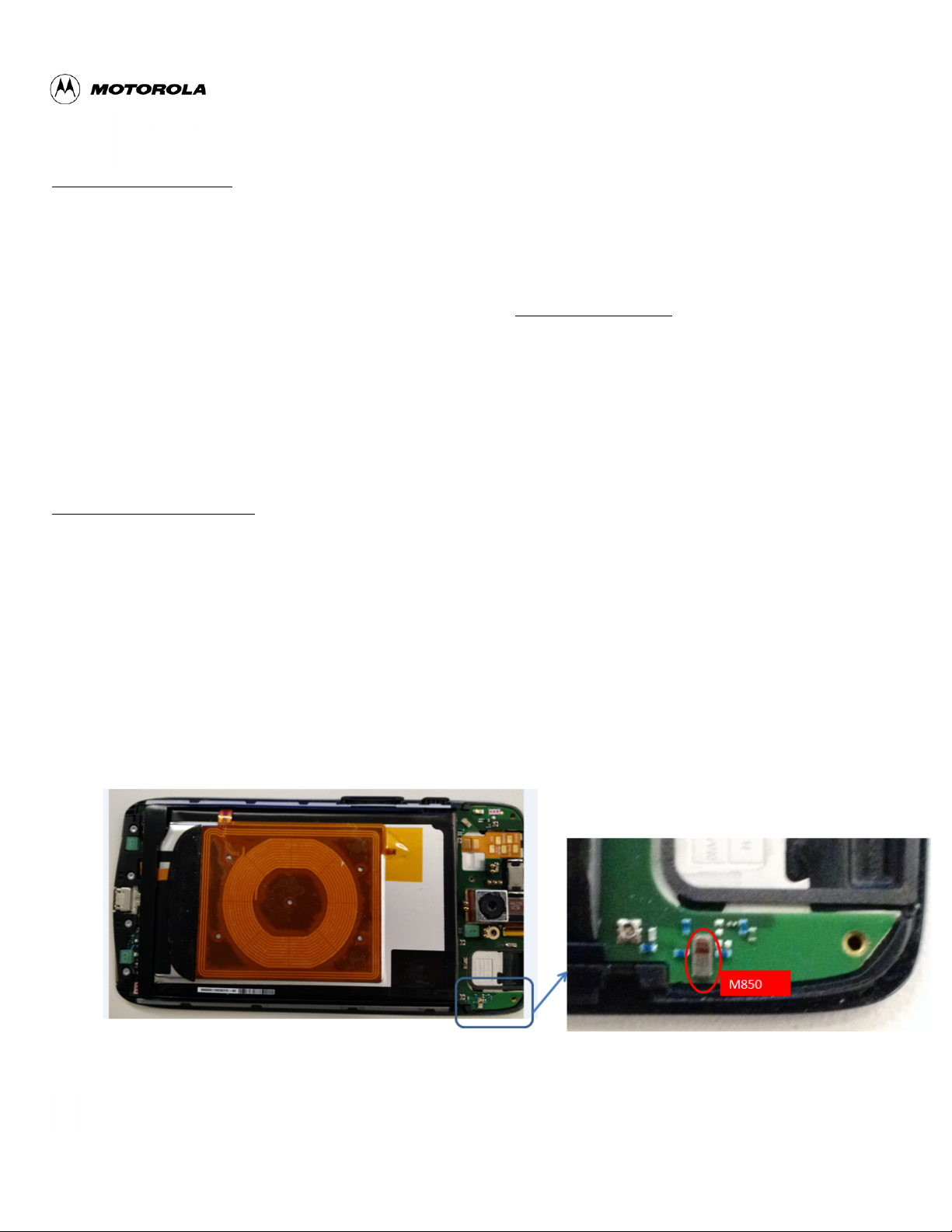
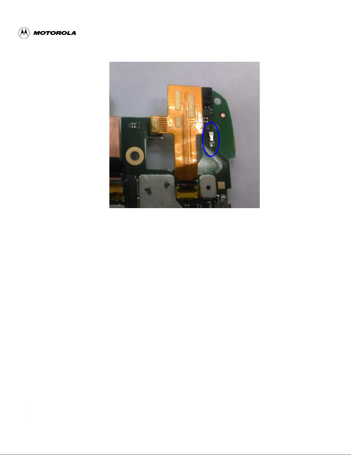
Step 2: If Step 1 does not resolve issue, check if universal contact (RefDes = M850) on the PCB
is damaged. Is it touching the antenna pad? If the universal clip is twisted or not making contact,
this needs to be replaced:
Figure 1: Universal contact for secondary antenna
Page 4
L3 Radiated Troubleshooting Guide XT1225/XT1254 PAGE 4 OF 21 PAGES
Motorola Mobility Inc. Confidential Restricted
v1.0
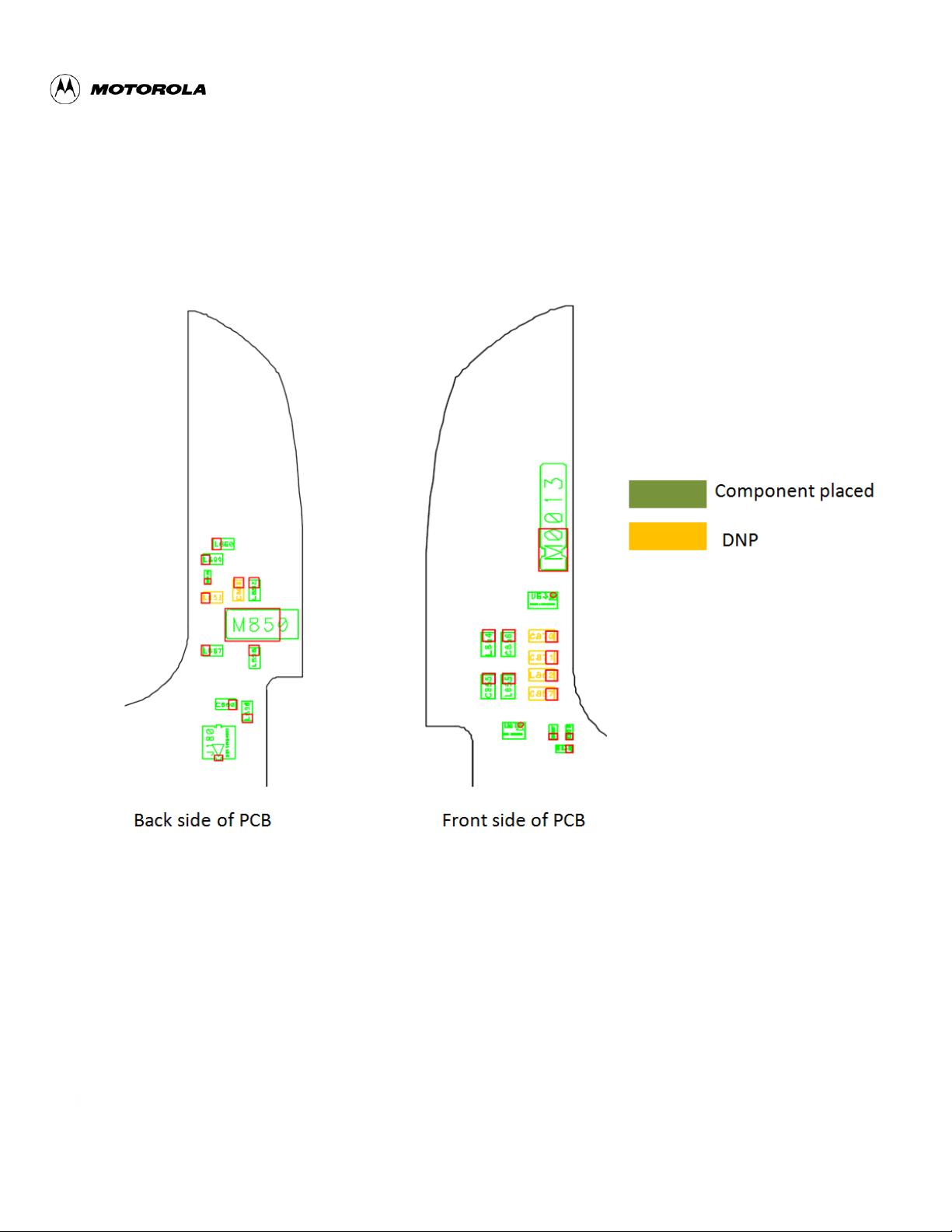
Step 3: If Step 2 does not resolve the problem check if components RefDes = L850, L899, L852,
L854, C856, L855, C855, L857, L858, L898 and C860 are placed correctly on PCB as shown
below in figures 2 and 3.
Figure 2: Antenna matching components, universal clip, & RF connector for secondary
antenna
Page 5
L3 Radiated Troubleshooting Guide XT1225/XT1254 PAGE 5 OF 21 PAGES
Motorola Mobility Inc. Confidential Restricted
v1.0
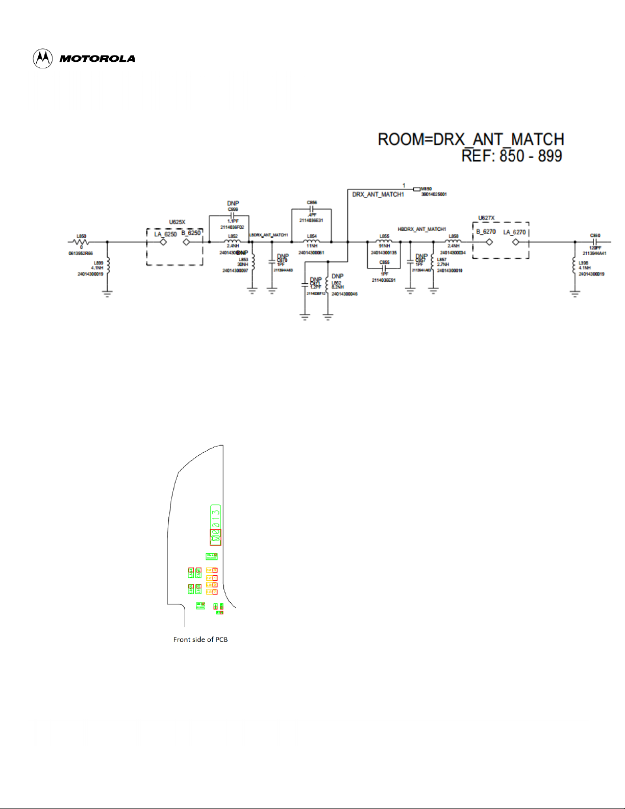
Figure 3: Secondary antenna matching components schematic
Step 4: If Step 3 does not resolve the problem, check if the ground clips M013 are placed on the
board and making contact as shown in Figure 4.
Figure 4: Bottom Ground Clip On the PCB
Page 6

L3 Radiated Troubleshooting Guide XT1225/XT1254 PAGE 6 OF 21 PAGES
Motorola Mobility Inc. Confidential Restricted
v1.0
BT/WiFi
Page 7
L3 Radiated Troubleshooting Guide XT1225/XT1254 PAGE 7 OF 21 PAGES
Motorola Mobility Inc. Confidential Restricted
v1.0
Objective / Purpose:
● This document helps debug Bluetooth and 2.4 GHz / 5 GHz WIFI factory radiated test failures.
Setup:
● Schematic
● PCB Layout
● The following list are the tests from RADTEST section of the NTF_Pareto document
! WLAN_5.0GHZ_RAD_MEAS_CW_POW_LCH165
! WLAN_5.0GHZ_RAD_MEAS_CW_POW_LCH149
! WLAN_5.0GHZ_RAD_MEAS_CW_POW_LCH165_CL
! WLAN_5.0GHZ_RAD_MEAS_POW_STATUS_LCH149
! WLAN_5.0GHZ_RAD_MEAS_CW_POW_LCH149_CL
! WLAN_2.4GHZ_RAD_MEAS_CW_POW_LCH01
! WLAN_2.4GHZ_RAD_MEAS_CW_POW_HCH13
! WLAN_5.0GHZ_RAD_MEAS_CW_POW_LCH036_CL
! WLAN_2.4GHZ_RAD_MEAS_CW_POW_MCH06
! WLAN_5.0GHZ_RAD_MEAS_CW_POW_LCH036_MID
Ant.%contact%
L016%
Page 8

L3 Radiated Troubleshooting Guide XT1225/XT1254 PAGE 8 OF 21 PAGES
Motorola Mobility Inc. Confidential Restricted
v1.0
Analysis:
● Bluetooth / WiFi 2.4GHz
○ BT_RAD_MEAS_CW_POW_CH_00
○ WLAN_2.4GHZ_RAD_MEAS_CW_POW_LCH01
○ WLAN_2.4GHZ_RAD_MEAS_CW_POW_HCH13
○ WLAN_2.4GHZ_RAD_MEAS_CW_POW_MCH06
Step 1: Retest
Step 2: Check for cracks in the WiFi antenna pattern
Cracks will only be visible under a microscope. A known “good” top carrier should be placed and
the phone should be re-tested.
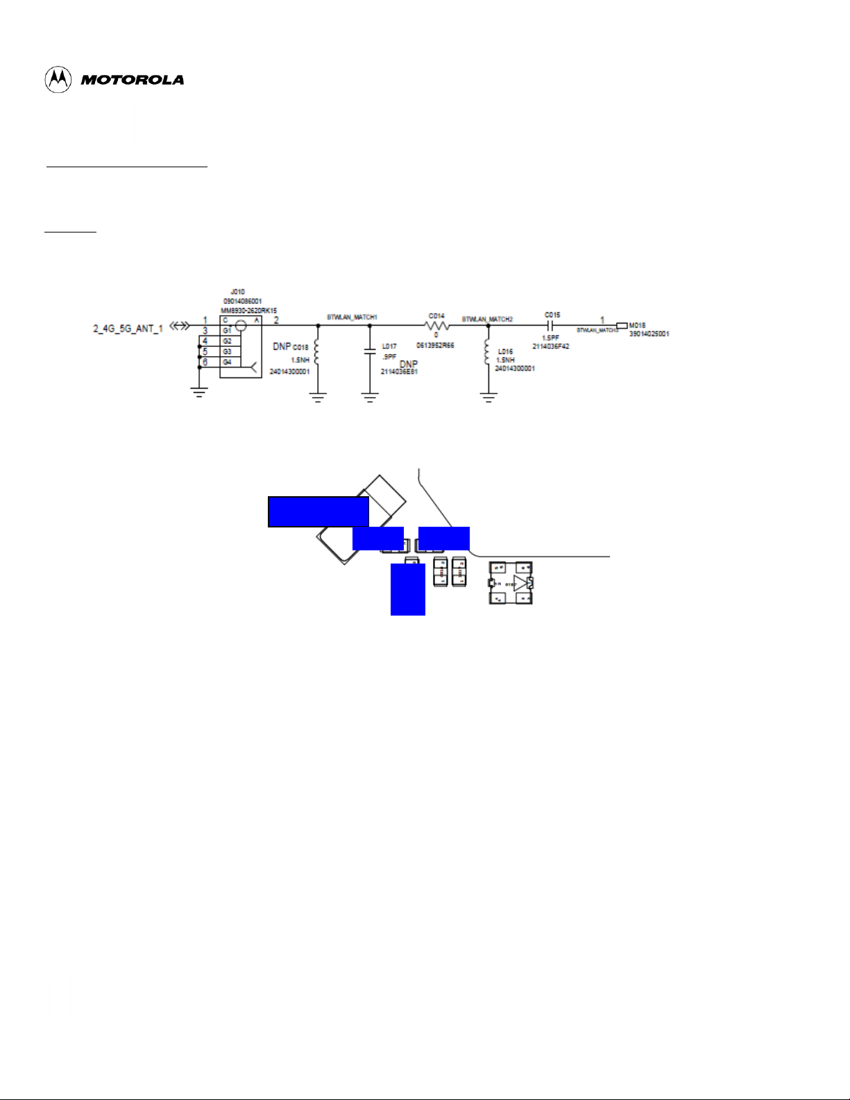
Step 3: Check if antenna C clip contact on PCB is missing, damaged or not making good
contact with antenna. The contact should look like this picture below:
Check&antenna&cracking&
Page 9

L3 Radiated Troubleshooting Guide XT1225/XT1254 PAGE 9 OF 21 PAGES
Motorola Mobility Inc. Confidential Restricted
v1.0
Step 4: Check if antenna is matching components RefDes C014 (0 ohm), C015 and L016 are
intact.
Check&antenna&contact&C&clip&
Ant.%contact%
L016%
Page 10

L3 Radiated Troubleshooting Guide XT1225/XT1254 PAGE 10 OF 21 PAGES
Motorola Mobility Inc. Confidential Restricted
v1.0
Step 5: Check if PCB to chassis grounding M0019 intact and making good contact.
%
M0019%
Page 11
L3 Radiated Troubleshooting Guide XT1225/XT1254 PAGE 11 OF 21 PAGES
Motorola Mobility Inc. Confidential Restricted
v1.0
● WiFi 5GHz
WLAN_5.0GHZ_RAD_MEAS_CW_POW_
o LCH165
o LCH149
o LCH165_CL
o STATUS_LCH149
o LCH149_CL
o LCH036_MID
o LCH036_CL
When 5 GHz radiated Wi-Fi test failed, most likely it is conducted problem, if conducted circuit
was confirmed to be good, please follow the same steps as Wi-Fi 2.4G to debug.
Page 12

L3 Radiated Troubleshooting Guide XT1225/XT1254 PAGE 12 OF 21 PAGES
Motorola Mobility Inc. Confidential Restricted
v1.0
GPS
Page 13

L3 Radiated Troubleshooting Guide XT1225/XT1254 PAGE 13 OF 21 PAGES
Motorola Mobility Inc. Confidential Restricted
v1.0
Objective / Purpose:
This document helps debug GPS factory radiated test failures
○ GPS_CARRIER_TO_NOISE
Setup:
● Schematic
● PCB Layout
%
C056%
Ant.%Contact%
%
Page 14

L3 Radiated Troubleshooting Guide XT1225/XT1254 PAGE 14 OF 21 PAGES
Motorola Mobility Inc. Confidential Restricted
v1.0
Analysis:
Step 1: Retest
Step 2: check for cracks in the GPS antenna pattern
Cracks will only be visible under a microscope. A known “good” top carrier should be placed and
the phone should be re-tested.
Step 3: Check if antenna C clip contact on PCB is missing, damaged or not making good
contact with antenna. The contact should look like this picture below:
Step 4: Check if antenna matching components RefDes C056 and L056 are intact.
Page 15

L3 Radiated Troubleshooting Guide XT1225/XT1254 PAGE 15 OF 21 PAGES
Motorola Mobility Inc. Confidential Restricted
v1.0
Step 5: If the Carrier-to-noise is several dB lower than the spec, check if the PCB around the
hole has crack or not.
Step 6: If the C/N is more than 15dB lower than spec, check if the RF connector is aligned with
solder pads and if the center pin soldered well. The resistance between 2 center pins of RF
connector should be 0 ohm.
Page 16

L3 Radiated Troubleshooting Guide XT1225/XT1254 PAGE 16 OF 21 PAGES
Motorola Mobility Inc. Confidential Restricted
v1.0
Main Antenna
Page 17

L3 Radiated Troubleshooting Guide XT1225/XT1254 PAGE 17 OF 21 PAGES
Motorola Mobility Inc. Confidential Restricted
v1.0
Objective / Purpose:
● Studying radiated main antenna failures and providing procedure for debugging the failures
● The following tests from AUDIORAD station
Here are the various test cases for the Verizon SKU Failure List (Primary, C2): Verizon Primary
● QC_LTE_BC13_C0_TX_RAD_POW_23230
● QC_LTE_BC4_C0_RX_RAD_RSSI_HCH2350
● QC_LTE_BC04_C0_TX_RAD_POW_20000
● QC_LTE_BC07_C0_TX_RAD_POW_20800
● QC_CDMA_800_C0_RAD_RSSI_HCH
● QC_CDMA_1900_C0_RAD_RSSI_HCH
● QC_WCDMA_1900_C0_TX_RAD_POW_9671
Verizon CDMA Primary
For factory radiated test failure, please do the following:
Step 1: Retest
Step 2: If retest does not pass, check if the unit has the bottom antenna carrier assembled
correctly. The Quantum bottom antenna carrier should look like Figure 1. Make sure all the
screws to hold the bottom carrier are placed.
Figure 1: Quantum Bottom Antenna Carrier
Page 18

L3 Radiated Troubleshooting Guide XT1225/XT1254 PAGE 18 OF 21 PAGES
Motorola Mobility Inc. Confidential Restricted
v1.0
Step 3: if Step 2 does not resolve issue, check if universal contact (RefDes = M650) on the PCB
is damaged. Is it touching the antenna pad? If the universal clip is twisted or not making contact,
this needs to be replaced:
Step 4: If Step 3 does not resolve the problem check the following components for each test
failure (component placement shown in figures 2 and 3):
● QC_LTE_BC13_C0_TX_RAD_POW_23230
● First check: C107, U651, L663, C656, C654
● If all intact and soldered well, check: C651, L655, C670, C653, L652, L651, U630,
R9008, and R9009
● If all intact and soldered well, check: L656, L658, L660, C127, U653, U655, R9010,
and R9011
● QC_LTE_BC4_C0_RX_RAD_RSSI_HCH2350
● First Check: C656, C654, U653, C127, R9010, and R9011
● If all intact and soldered well, check: L663, L656, L658, L660, and U655
● If all intact and soldered well, check: C651, L655, C670, C653, L652, L651, C107,
U630, U651, R9008, and R9009
● QC_LTE_BC04_C0_TX_RAD_POW_20000
● First Check: C656, C654, U653, U655, C127, R9010, R9011
● If all intact and soldered well, check: L663, L656, L658, L660, and C127
● If all intact and soldered well, check: C651, L655, C670, C653, L652, L651, C107,
U630, U651, R9008, and R9009
● QC_LTE_BC07_C0_TX_RAD_POW_20800
● First Check: C656, C654, U653, U655, C127, R9011
● If all intact and soldered well, check: L663, L656, L658, L660, C127, and R9010
Page 19

L3 Radiated Troubleshooting Guide XT1225/XT1254 PAGE 19 OF 21 PAGES
Motorola Mobility Inc. Confidential Restricted
v1.0
● If all intact and soldered well, check: C651, L655, C670, C653, L652, L651, C107,
U630, U651, R9008, and R9009
● QC_CDMA_800_C0_RAD_RSSI_HCH
● First check: C107, U651, R9009, L652, L655, L663, C656, L656, C654
● If all intact and soldered well, check: C651, C670, C653, L651, U630, and R9008
● If all intact and soldered well, check: L658, L660, C127, U653, U655, R9010, and
R9011
● QC_CDMA_1900_C0_RAD_RSSI_HCH
● First Check: C651, C656, C654, U653, U655, C127, R9011
● If all intact and soldered well, check: L663, L656, L658, L660, and R9010
● If all intact and soldered well, check: L655, C670, C653, L652, L651, C107, U630,
U651, R9008, and R9009
● QC_WCDMA_1900_C0_TX_RAD_POW_9671
● First Check: C651, C656, C654, U653, U655, C127, R9011
● If all intact and soldered well, check: L663, L656, L658, L660, and R9010
● If all intact and soldered well, check: L655, C670, C653, L652, L651, C107, U630,
U651, R9008, and R9009
Page 20

L3 Radiated Troubleshooting Guide XT1225/XT1254 PAGE 20 OF 21 PAGES
Motorola Mobility Inc. Confidential Restricted
v1.0
Figure 2: Main Antenna matching components overlay – Rear components
Page 21

L3 Radiated Troubleshooting Guide XT1225/XT1254 PAGE 21 OF 21 PAGES
Motorola Mobility Inc. Confidential Restricted
v1.0
Figure 3: Main Antenna matching components overlay – Front components
 Loading...