

Page 1
XT1225/XT1254
BASEBAND TROUBLESHOOTING GUIDE
Sept 18, 2014
Motorola Mobility Confidential Proprietary
Page 2

Sept 18, 2014
2
Page
Motorola Mobility Confidential Proprietary
TABLE OF CONTENTS
1. Snapshots of Antennas ………………………..………………….………………………..... 3
2. Snapshots/plots of Main Board .….…………….……………….………………..…………. 5
3. Touch Troubleshooting……………...…….………………….……………………..……….. 9
4. Display Troubleshooting…………….…….………………………………………..…….…. 15
5. Audio Troubleshooting……………………………………………………………………….. 21
6. No Power up Troubleshooting………………………………………………………………. 34
7. Battery & Charger Troubleshooting……………………………………….………………... 47
8. Sensors and SIM Troubleshooting …..……………………………………..……………… 55
9. Camera Troubleshooting…………………………………………………………………….. 66
10. BT & WiFi Troubleshooting……………………………………………………………………80
11. NFC Troubleshooting……………………………………………………………….…………92
Page 3

Sept 18, 2014
3
Page
Motorola Mobility Confidential Proprietary
SNAPSHOTS OF ANTENNAS
Page 4
Sept 18, 2014
4
Page
Motorola Mobility Confidential Proprietary
GPS Rx Only
BT/WLAN Tx/Rx
Diversity Rx Only
Antenna Locations
Main Antenna Tx/Rx
Page 5

Sept 18, 2014
5
Page
Motorola Mobility Confidential Proprietary
SNAPSHOTS/PLOTS OF MAIN
BOARD
Page 6
Sept 18, 2014
6
Page
Motorola Mobility Confidential Proprietary
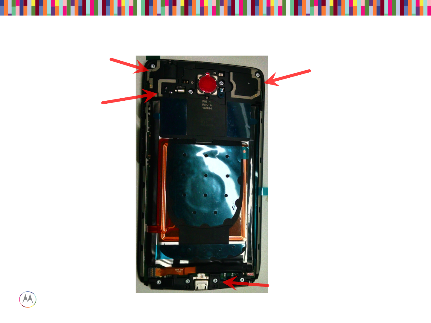
Top Side (Display)
Bottom Side (Battery)
Snapshots of Main PCB
Page 7
Sept 18, 2014
7
Page
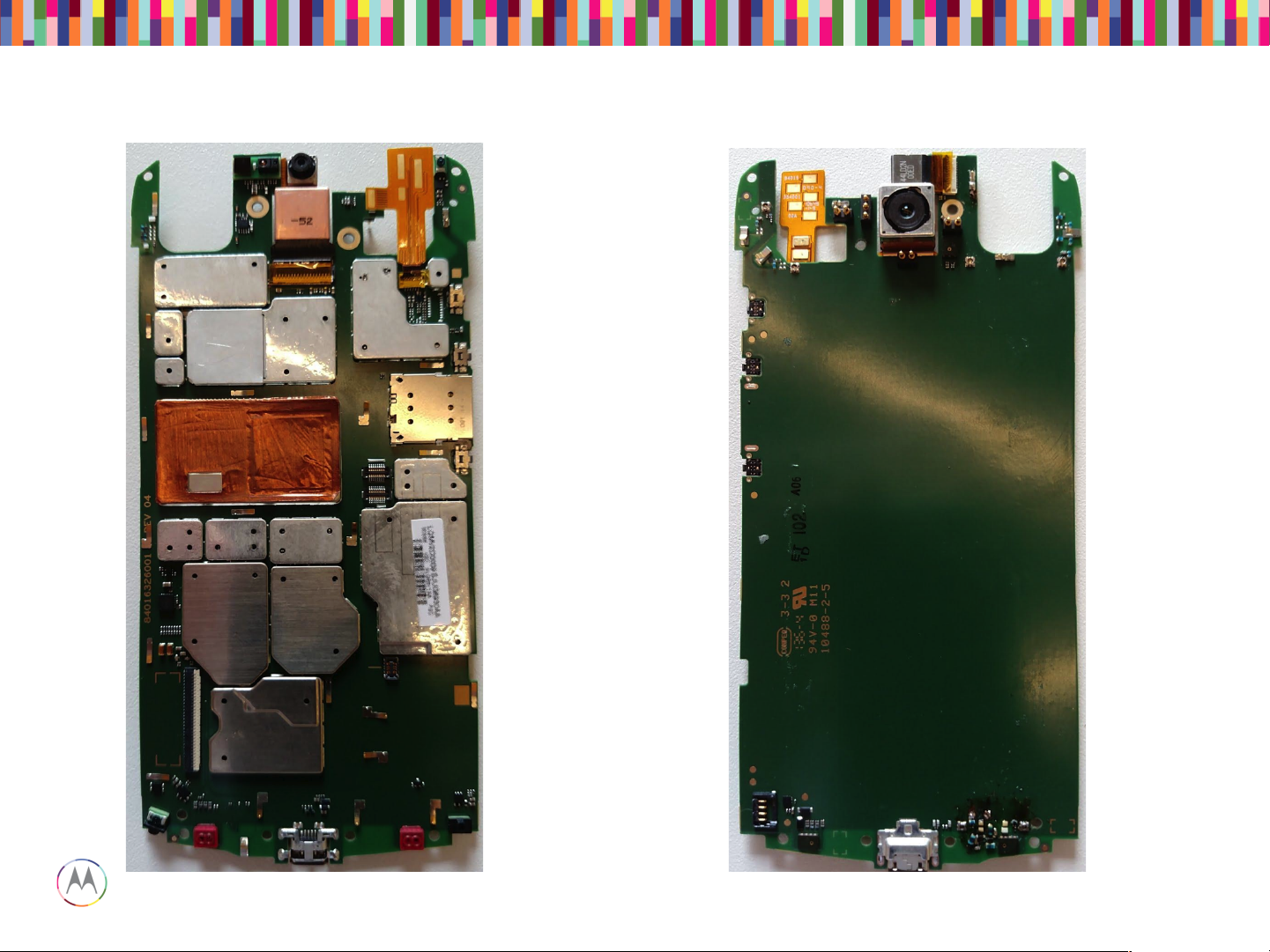
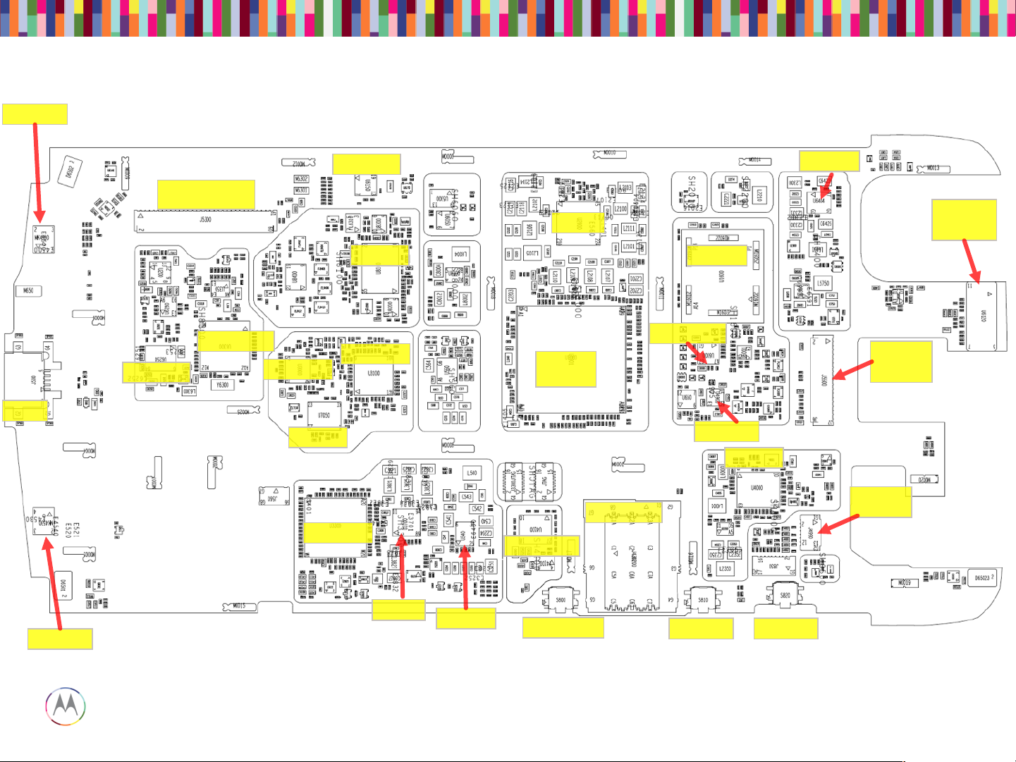
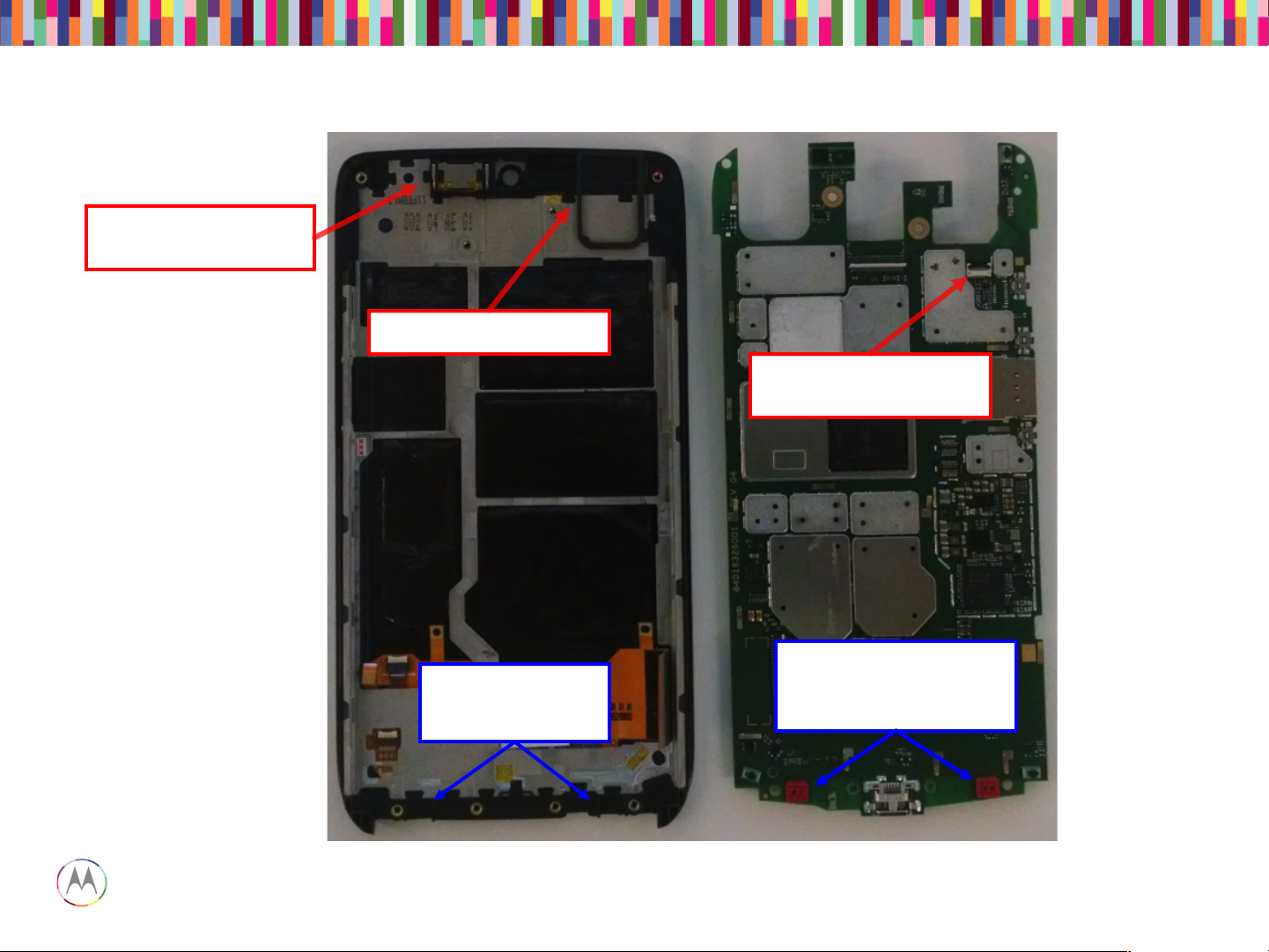
Motorola Mobility Confidential Proprietary
WTR1625L
PM8084
APQ8084
+ RAM
eMMC
Rear
Camera
ZIF
Headset /
Vibe ZIF
SIM Socket
Headset IC
Display and touch
Connector
USB
Power Key
Vol up key
Vol down key
Main Board – Top Placement
PROX
Sensor /
ALS
MDM9x25M
PM8019
SMB1359
QCA6164
BCM20795
STM32F401
TFA9890
MPU-6515
MMPA
WFR1620
RFFE
TMS320C5545
WCD9320
Mic 1
Mic 4
Page 8
Sept 18, 2014
8
Page
Motorola Mobility Confidential Proprietary
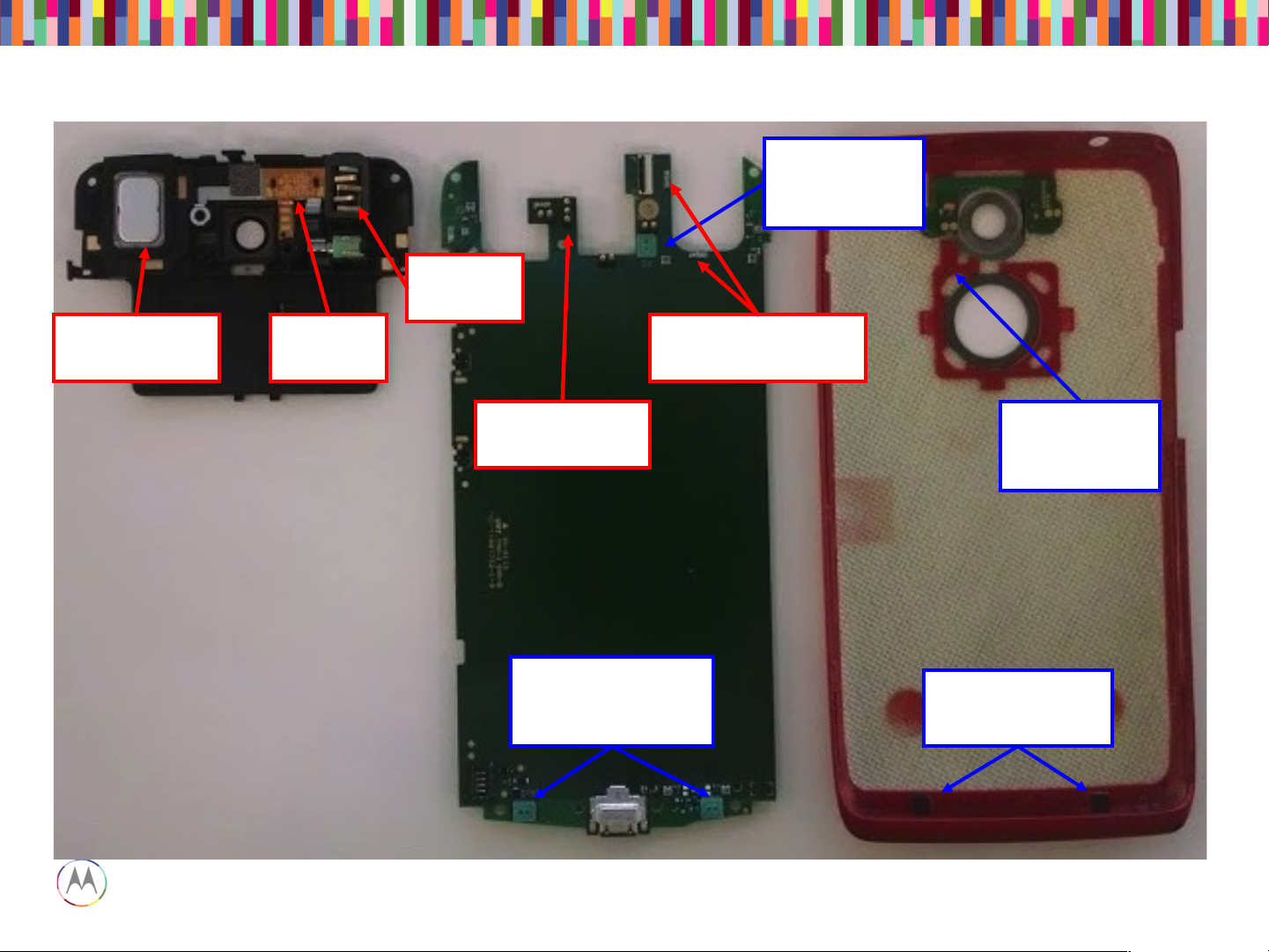
Main Board – Bottom Placement
Battery Con.
MIC 2
Loud Spk
Contact
Front
Camera
ZIF
Flash LED
pogo pins
MIC 3
MIC 5 (not
used)
Page 9

Sept 18, 2014
9
Page
Motorola Mobility Confidential Proprietary
TOUCH TROUBLESHOOTING
Page 10
Sept 18, 2014
10
Page
Motorola Mobility Confidential Proprietary
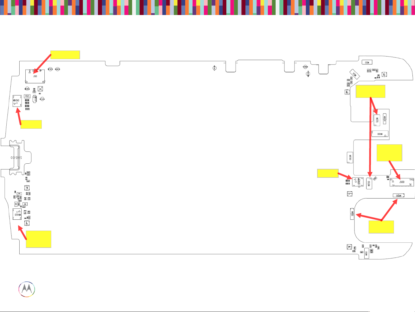
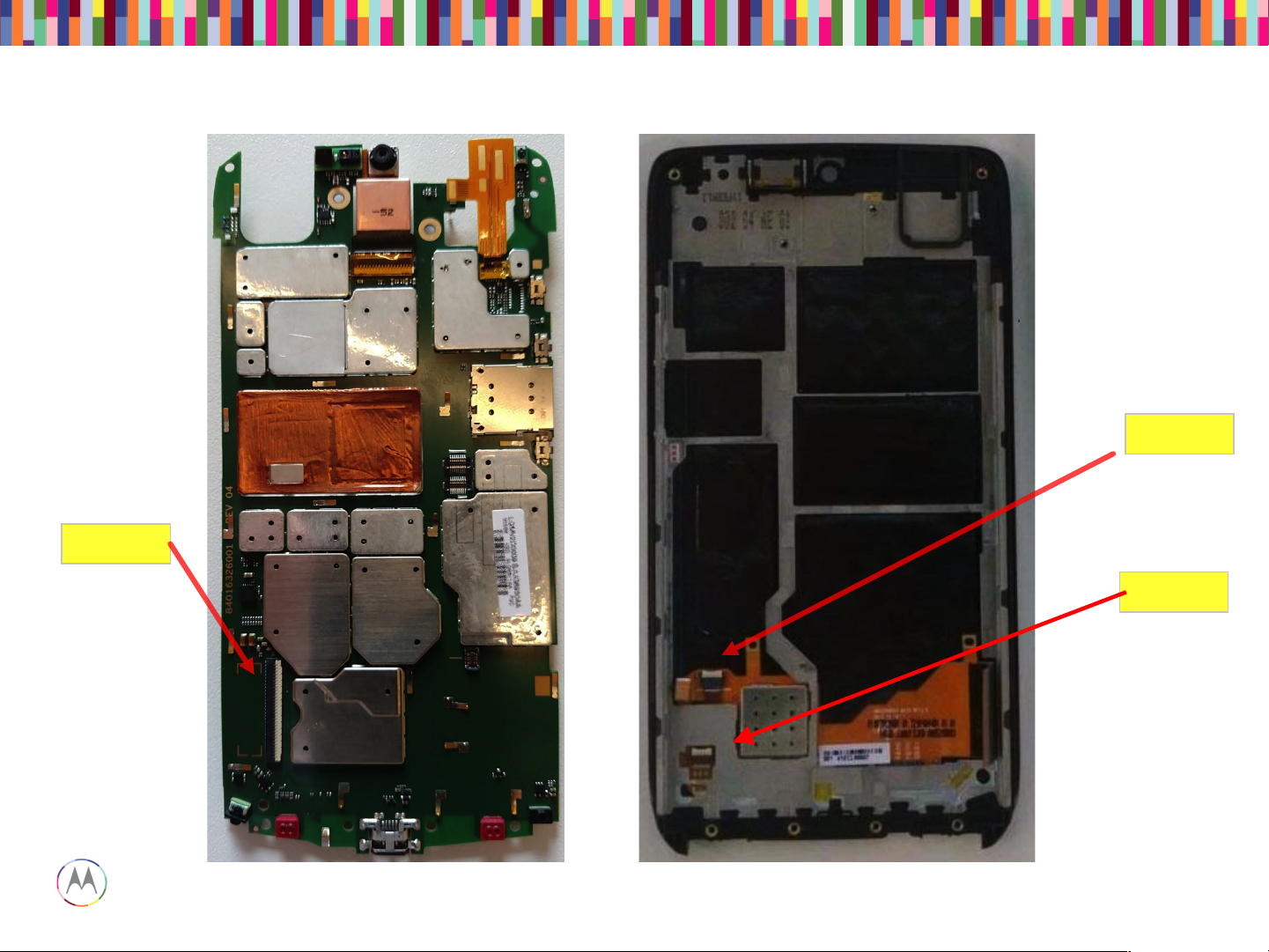
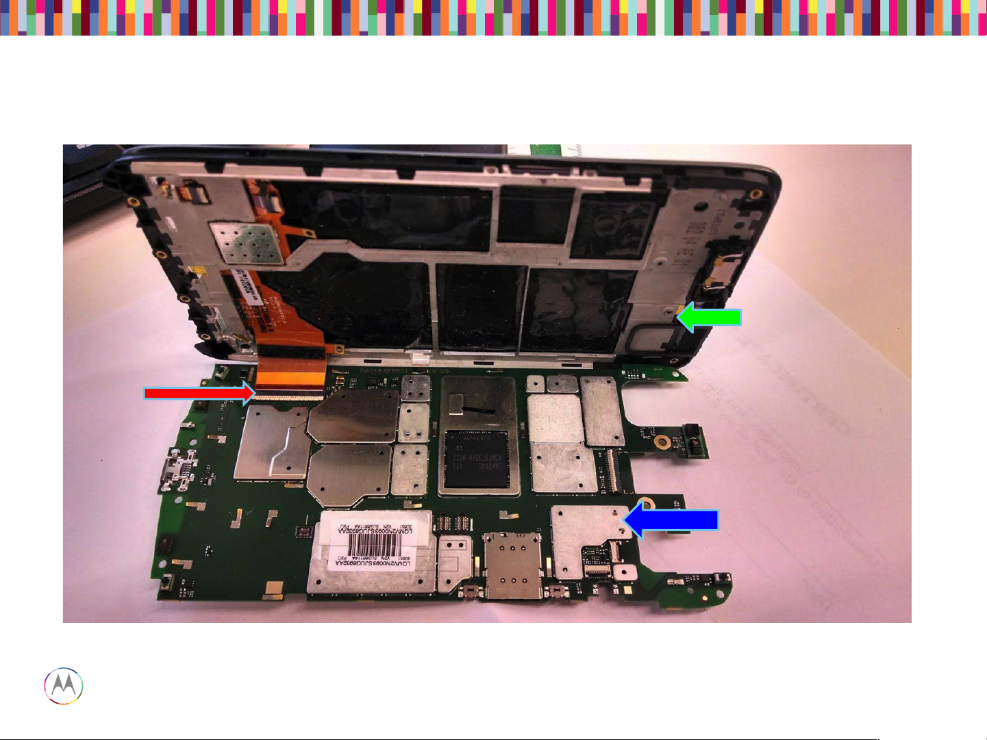
Display ZIF
Touch ZIF
Main Board – Location of LCD and touch ZIF connectors
TSB ZIF
Page 11
Sept 18, 2014
11
Page
Motorola Mobility Confidential Proprietary
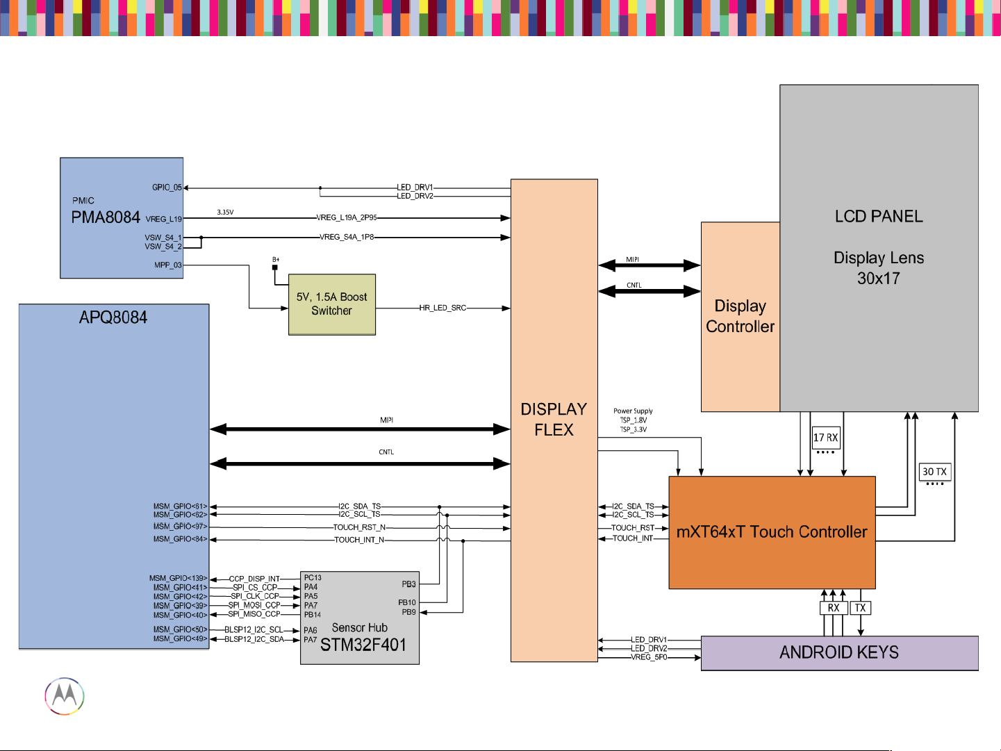
Capacitive Touch Block Diagram
Page 12

Sept 18, 2014
12
Page
Motorola Mobility Confidential Proprietary
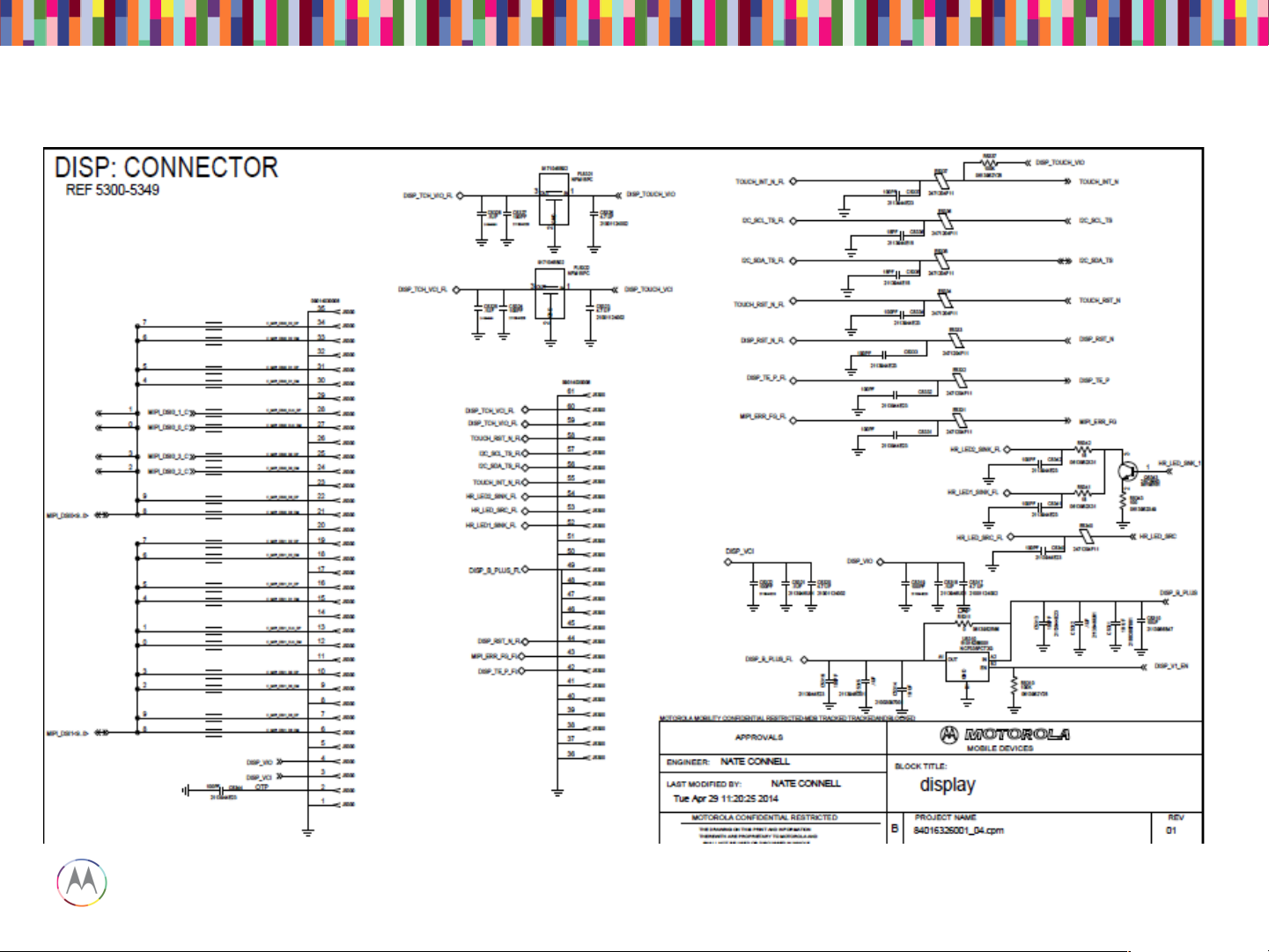
Display/Touch Connector
Page 13
Sept 18, 2014
13
Page
Motorola Mobility Confidential Proprietary
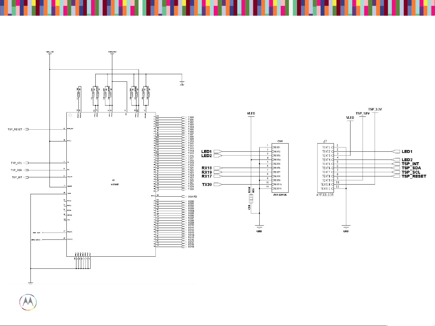
Touch IC Schematic
Page 14

Sept 18, 2014
14
Page
Motorola Mobility Confidential Proprietary
1. No Touch response when display touched
• Swap display panels with known good panel. If touch works, problem with
display flex or IC (Go to 3). If still not working, problem with main board
(Go to 2).
2. Main Board Issue
• Check touch connector for proper insertion of flex.
• Ensure 3.2VDC power is at the display ZIF.
• Verify Reset signal is high, IRQ is high.
• I2C Data and I2C Clock at 1.8VDC.
3. Display panel issue
• Check Touch flex for any damage.
• Ensure 3.2VDC and 1.8 VDC supplies are at the touch ZIF.
• Verify Reset signal is high, IRQ is high, I2C Data and Clock at 1.8VDC.
• When touching panel, INT should toggle low, I2C data and clk will toggle.
Touch Troubleshooting
Page 15

Sept 18, 2014
15
Page
Motorola Mobility Confidential Proprietary
DISPLAY TROUBLESHOOTING
Page 16

Sept 18, 2014
16
Page
Motorola Mobility Confidential Proprietary
• This display is a color Active Matrix Organic Light Emitting Diode
(AMOLED) of glass construction with White pixels on a Black
background.
• The display consists of high density pixels with a color depth of 16.7M
colors (24 bpp). The display interface is two MIPI DSI ports MIPI in
command mode.
• Chip-on-glass (COG) with the driver located at bottom front of panel.
• 2 LEDs on flex for android key backlighting.
• Display operates in MIPI command mode with onboard RAM.
Display
Page 17
Sept 18, 2014
17
Page
Motorola Mobility Confidential Proprietary
61-pin
display
ZIF
connector
Display Module
Main PCB
Assembly
Page 18
Sept 18, 2014
18
Page
Motorola Mobility Confidential Proprietary
Display Main Schematic
Page 19
Sept 18, 2014
19
Page
Motorola Mobility Confidential Proprietary
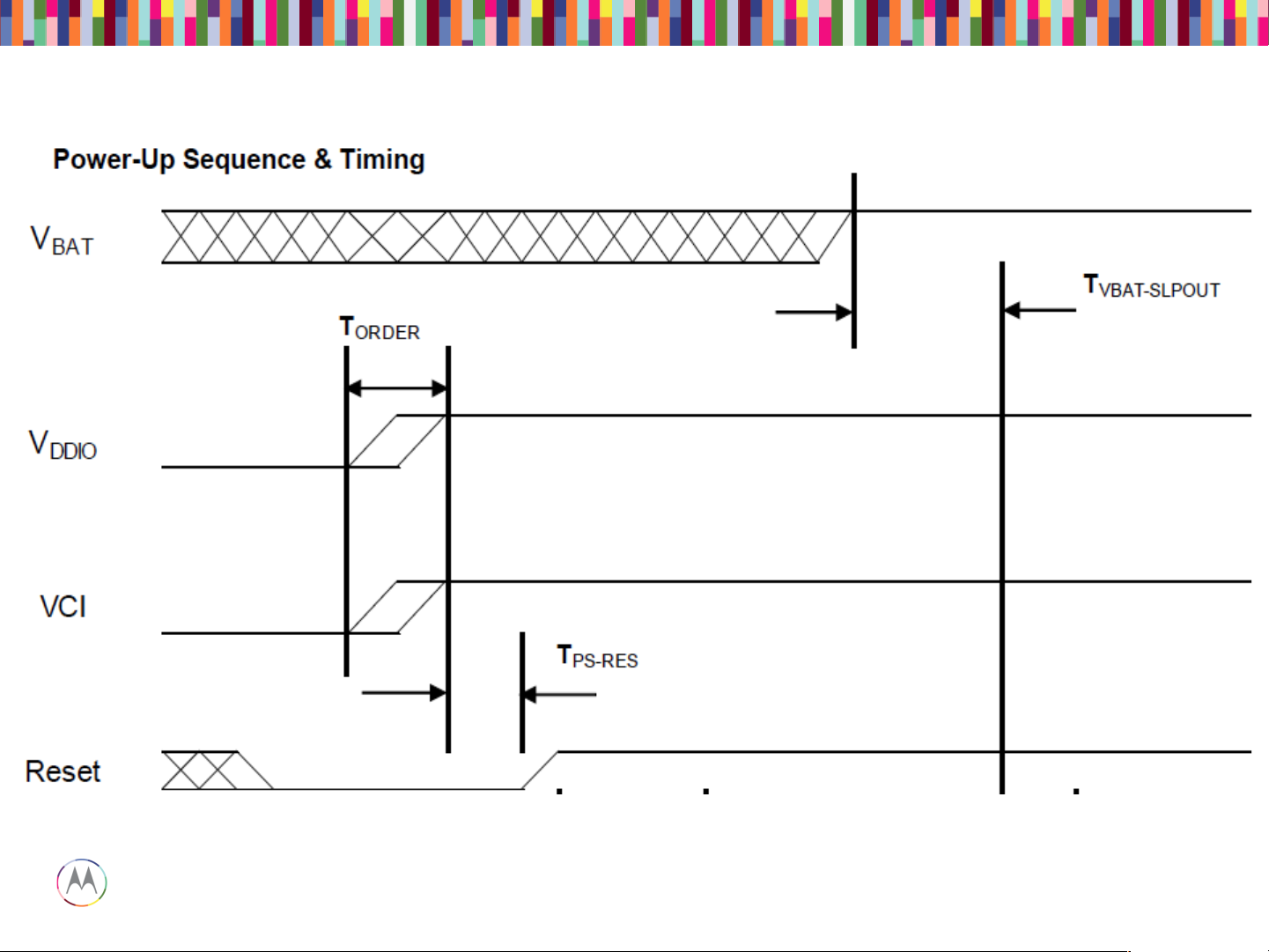
Pin45~49 of J5300; Vbat from C5314
Pin4 of J5300; Vddio from C5317
Pin3 of J5300; Vddio from C5320
Pin44 of J5300; RST from E5333
Power-up Sequence
Page 20

Sept 18, 2014
20
Page
Motorola Mobility Confidential Proprietary
• Check 61pin display ZIF connector
1. Properly inserted
2. Any damage to ZIF receptacle on main PCB or plug on disp flex tail
3. Swap in known good main PCB or good disp module to see if issue
follows main PCB or display flex
• If the issue follows main PCB
1. Check DISP_B_PLUS (Vbat) voltage (3.15 to 4.4VDC) at Pin45~49 of
J5300
2. Check DISP_VIO voltage (1.8VDC) at Pin4 of J5300
3. Check DISP_VCI voltage (3.1VDC) at Pin3 of J5300
4. Check above 3 voltages after phone power up. If they are not turned
on, check them during phone power up.
• If the issue follows display module, replace the module.
Display Troubleshooting
Page 21

Sept 18, 2014
21
Page
Motorola Mobility Confidential Proprietary
AUDIO TROUBLESHOOTING
Page 22
Sept 18, 2014
22
Page
Motorola Mobility Confidential Proprietary
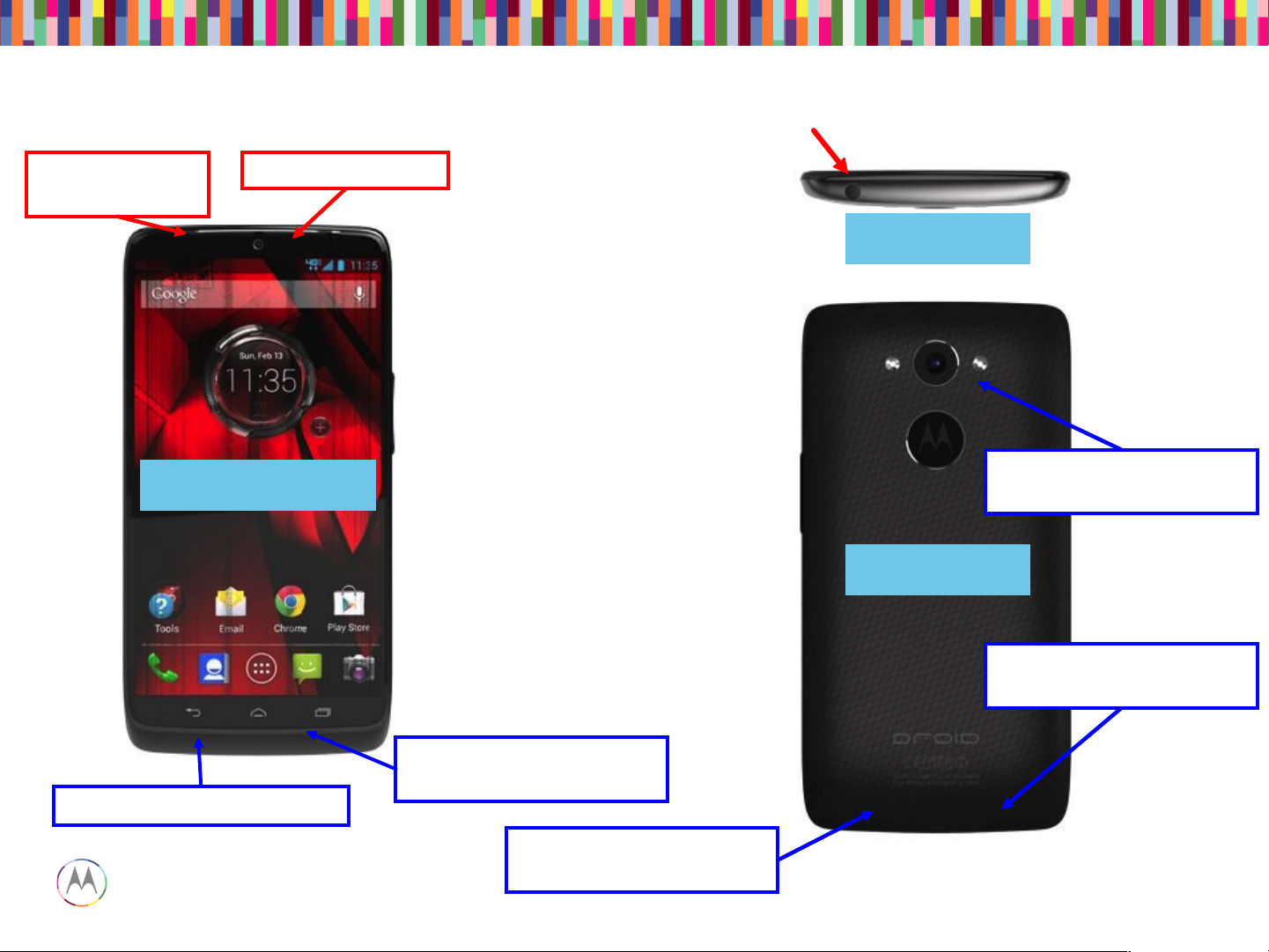
Quarternary Microphone
Port
Loudspeaker
Port
Front View
Back View
Earpiece Port
Top View
Primary Microphone port
Secondary Microphone
Port
Quinary Microphone
Port
Tertiary Microphone
Port
Audio Devices
Page 23
Sept 18, 2014
23
Page
Motorola Mobility Confidential Proprietary
Microphone
Mesh Assembly
Headset jack flex
connector
Primary (left) &
Quarternary (right)
mic & grommets
Loudspeaker Gasket
Earpiece speaker
(32 ohms)
Audio Devices (PCB View)
Page 24
Sept 18, 2014
24
Page
Motorola Mobility Confidential Proprietary
Tertiary (left) &
Quinary (right)
mic and grommet
Earpiece pogo
connector
Loudspeaker
spring contacts
Secondary
Microphone
Port
Microphone
Mesh Assembly
Secondary
Microphone
& Grommet
Loudspeaker
(8 ohms)
Earpiece
Flex
Headset
Jack
Audio Devices (PCB View)
Page 25

Sept 18, 2014
25
Page
Motorola Mobility Confidential Proprietary
• Launching the CQA app will help resolve and root-cause the vast
majority of problems
• Go to the phone/dialer and enter *#*#2486#*#*
• The CQA main menu will pop-up – select “Start CQA Test in Menu
Mode”
• Select the appropriate debug area – for Audio, primarily you will use
AUDIO and HEADSET
• The AUDIO CQA area has test capability for both mics, earpiece and
loudspeaker
• The HEADSET CQA area should be used to debug any detection, or
lack of audio on the headset jack path
CQA Application
Page 26

Sept 18, 2014
26
Page
Motorola Mobility Confidential Proprietary
• The CQA apk can be used to verify a broken audio path. Under the “Audio” menu, select
“Mic Loopback”.
– The “PRIMARY MIC” setting allows a mic1 to earpiece loopback (recommended)
• Note* - The “DEFAULT MIC” setting also allows this, if a headset device is not
plugged in.
– The “SECONDARY MIC” setting loops mic2 to the earpiece, and so on.
– *NOTE* The “SECONDARY MIC LPA” path does not exist in HW and will not
loopback any audio.
• If both of those are not functional, the earpiece speaker path is likely damaged. In the
“AUDIO” menu of the CQA apk, select “Ear Speaker” and then “Play Harvard speech
pattern” and/or “Buzz Sweep”.
• The loudspeaker can be tested by selecting “Loudspeaker” via the CQA apk. A musical
composition should start playing and be easily heard.
• If audio is not present on the HEADSET path, select the “Headset” entry in the main menu
of the CQA app, then plug-in the headset device to view whether the lack of audio is a
detection-cycling issue or other anomaly.
“No Audio” Complaints
Page 27
Sept 18, 2014
27
Page
Motorola Mobility Confidential Proprietary
Microphones
Page 28

Sept 18, 2014
28
Page
Motorola Mobility Confidential Proprietary
If a mic is not functioning…
• Check to make sure the microphone and mic ports are not blocked.
• Check to make sure the mic gasket and mic grommets are seated properly.
• Check the microphone for diaphragm debris indicating a shattered diaphragm. Look under a
microscope to view inside the microphone port for damage or debris.
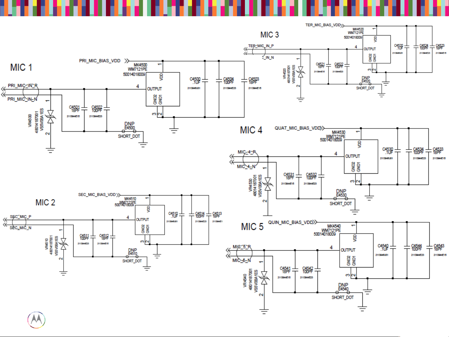
• Check to make sure none of the capacitors on the mic lines are shorted or damaged.
• Check the mic bias C4500 (Mic1), C4510 (Mic2), C4520 (Mic3), C4530 (Mic4), C4540 (Mic5).
The mic bias should be 2.8V when the microphone is enabled.
• If the failure is no microphone audio, check mic loopback through CQA at the board level with
a display connected. (Mic loopback may be easier to check with a headset plugged in)
• If there is no audio during mic loopback, inject a 35mVrms, 1kHz sine wave onto the
MIC_IN_P side of C4501 (Mic1), C4511 (Mic2), C4521 (Mic3), C4531 (Mic4), C4541 (Mic5)
and listen for the tone during loopback. If you can hear the tone now, you know either the mic
is bad, or there’s a process defect with the mic-to-PCB connection.
• X-ray the mic to check for process defects.
• If there is an issue with Mic5 LPA path, also check U6281 and the components around it for
process defects.
Microphones Troubleshooting
Page 29
Sept 18, 2014
29
Page
Motorola Mobility Confidential Proprietary
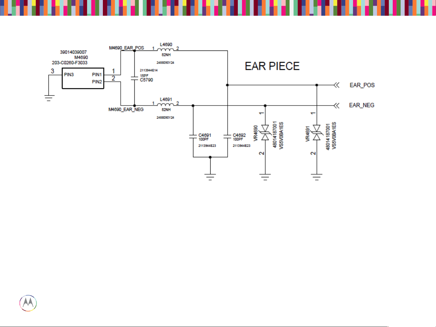
• Check that the impedance of the earpiece speaker is 32 ohms, and that the spring contacts are not
bent.
• Check that the earpiece flex is seated properly in the top carrier with no debris on it. You should also
be able to see slight imprints in the gold pads where both the speaker contacts and PCB pogo contacts
were touching the flex.
• Check that the earpiece pogo connector on the PCB is seated properly with no bent or stuck pogos.
• Check that L4690 and L4691 are not damaged or skewed. Also check C4691, C4692, C5790, VR4690
and CR4691 for any placement issues.
Earpiece Speaker (Handset Mode DOWNLINK)
Page 30
Sept 18, 2014
30
Page
Motorola Mobility Confidential Proprietary
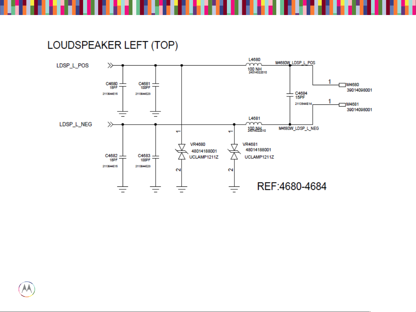
• Verify the impedance of the loudspeaker is 8 ohms.
• Verify the loudspeaker gasket is placed correctly.
• Lack of mechanical contact should also be checked (bent loudspeaker pins on PCB).
• Make sure L4680 and L4681 are not skewed or damaged.
• Check C4684, C4680, C4681, C4682, C4683, VR4680, and VR4681 for any placement issues.
Loudspeaker
Page 31
Sept 18, 2014
31
Page
Motorola Mobility Confidential Proprietary
3.5mm Headset Path
Page 32

Sept 18, 2014
32
Page
Motorola Mobility Confidential Proprietary
3.5mm Headset Path
Page 33

Sept 18, 2014
33
Page
Motorola Mobility Confidential Proprietary
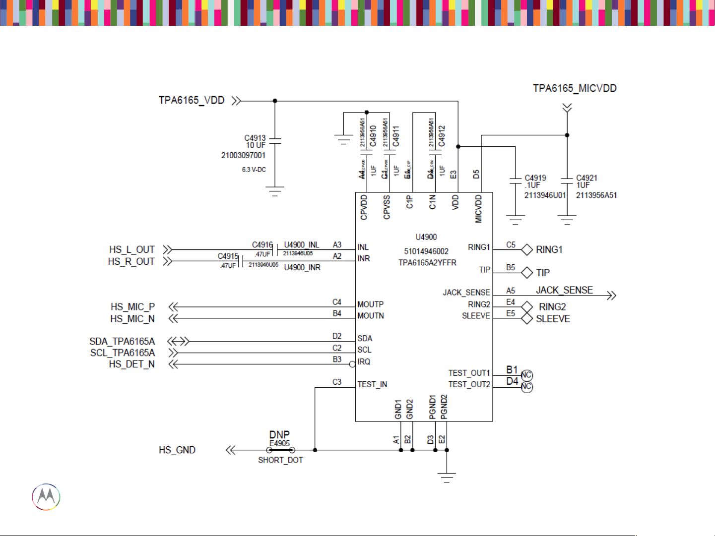
• Check the pins on the headset jack for any bent pins or missing pins (Top Carrier)
• Check to make sure the headset jack flex is properly aligned and fully inserted into the zif connector on
the PCB.
• On the PCB:
– Series components L4900, E4901, E4903, and L4904 must be physically placed and measured
using a DMM. Replace if any are found to be open circuit.
– ESD Diodes VR4900, VR4901, VR4902, VR4903, VR4904 must be open circuit. Measure these
with a DMM to ground. If any short circuit is found, replace the ESD diode.
– Shunt caps C4900, C4901, C4902, C4903, and C4904 must not be shorted across.
– Resistors R4900, R4901,R4902, and R4903 must be placed. These can be probed with a DMM,
where continuity must exist.
– U4900 must have voltage on the VDD line, and can be probed on C4913 or C4919. This should
measure 1.8V nominally.
– U4900 must have voltage on the MICVDD line (for uplink/headset mic audio to work). This can be
probed at C4921. This should measure ~2.8V.
3.5mm Headset Troubleshooting
Page 34

Sept 18, 2014
34
Page
Motorola Mobility Confidential Proprietary
NO POWER UP DEBUGGING
Page 35

Sept 18, 2014
35
Page
Motorola Mobility Confidential Proprietary
AP APQ APQ8084 U1000
BP MDM MDM U3300
AP PMIC PMA8084 U1000
BP PMIC PM8019 U3700
SMB Charger U540
Kung Pow Factory Kill IC Battery Pull IC U650/Q510
B_PLUS VSYS System Battery
Voltage
VBUS USB Voltage Charger Voltage
Glossary
Page 36

Sept 18, 2014
36
Page
Motorola Mobility Confidential Proprietary
• Generally the first step to troubleshooting a no turn on PCB is to look at its boot current. A
blank board (no software flashed yet) will normally draw about 60mA at a constant level.
• Also it is helpful to find out what level of functionality is available. These distinct modes
were observed:
1. Blank Flash mode
• Normally will enter this mode for a newly built PCB.
• Can be forced by shorting debug connector as shown in later slides.
2. Fastboot mode
• Normally will enter this mode after blank flashing bootloader into newly built
PCB.
• Can be forced using volume down key
3. Full Power up
• Will enumerate to PC as Motorola Network device and ready for board test.
• Failed boards will be able to achieve one of these modes but fail to get to the next. This bit
of information is useful for debugging.
• Start with the phone off, then plug in the USB cable. If the phone does not turn on when
the USB cable is inserted, there is most likely an issue with the connector.
• If the current is abnormally high for a blank board, the root cause is most likely a short.
Going through the power on sequence is helpful for finding shorts, it is shown on the next
page.
Debug Procedure
Page 37

Sept 18, 2014
37
Page
Motorola Mobility Confidential Proprietary
Measure USB/
Battery Current
Start
I < 100mA
I < 1mA
I > 1000mA
Check Input
Power Path
Check USB
Enumeration
High Current
Failure
Check PMA8084
Yes No
Yes
No
Yes
No
Check APQ8084
NTO Debug Flow Chart
Page 38

Sept 18, 2014
38
Page
Motorola Mobility Confidential Proprietary
Check Input
Power Path
C502 ≈ 5V
Yes No
Measure Input Voltages
C6122 ≈ 3.5V
Repair USB
Connector
(J500)
Repair SMB
(U540)
No
Check
PMA8084
(U2000)
Yes
Check Input Power Path
Page 39

Sept 18, 2014
39
Page
Motorola Mobility Confidential Proprietary
J510
Battery Connector
BATT_PLUS_CONN
J500
USB Connector
VBUS
J560
Wireless Coil
U540
SMB Charger
B_PLUS
U650
WCHG IC
WCHG_OUT_5V
U2300
Boost-Bypass
BPHI
U2210
5V Boost
VREG_5P0
U2000
AP PMIC
PMA8084
U3700
BP PMIC
PM8019
U???
RF Boost-Bypass
RF_BPHI
U8000
Envelope Tracker
QFE 1100
High Voltage
Regulators
(Vout > 2.7V)
Low Voltage
Regulators
(Vout < 2.7V)
U650
Battery Pull IC
"Kung Pow"
Q510
2.7V- 4.35V
2.7V- 4.35V
3.15V- 4.35V
3.30V- 4.35V
Kill Switch
Simplified Input Power Tree
Page 40

Sept 18, 2014
40
Page
Motorola Mobility Confidential Proprietary
Check
PMA8084
All
Regulators
Turn On?
Yes
Check Power
Up Sequence
Check USB
Enumeration
PS_HOLD =
1.8V
Yes
Repair APQ and
PoP (U1000)
No
No
Use XRay to
find Shorts near
PMA8084
(U2000)
Replace
PMA8084
Check PMA8084
Page 41

Sept 18, 2014
41
Page
Motorola Mobility Confidential Proprietary
Check Power-up Sequence
Page 42

Sept 18, 2014
42
Page
Motorola Mobility Confidential Proprietary
Check APQ8084
Check PoP
Alignment
XRay and Look
for Solder
Shorts
Replace APQ/
DDR
Check APQ8084
Page 43

Sept 18, 2014
43
Page
Motorola Mobility Confidential Proprietary
High Current
Failure
Use Thermal
Camera or Hand
to find Hot
Shield
Use Xray to find
Shorts on
B_PLUS, BPHI,
or BATT_CONN
High Current Failure
Page 44
Sept 18, 2014
44
Page
Motorola Mobility Confidential Proprietary
Check USB
Enumeraton
Blankflash
Mode
Yes
Device Enumerates
in...
Pull Device Logs
Reflash
Bootloader
Fastboot
Mode
Yes
No
Android
Device
Enumerates
?
No
Check
PMA8084
(U2000)
Check Debug
Connector
Reflash Android
Check eMMC
Check eMMC
Check
Ambulancing
(Reset Loop)
Check USB
Connector
(J520)
Check USB Enumeration
Page 45

Sept 18, 2014
45
Page
Motorola Mobility Confidential Proprietary
• If the current looks normal, check for enumeration to Qcom blank device.
Debug Procedure
• Sometimes if a board has software already flashed, or there was some problem with
software, a board can be forced into this mode by shorting two highlighted pins on the
debug connector:
• Then when board is in this mode, blank flashing can be attempted to find more information
on the failure.
Page 46

Sept 18, 2014
46
Page
Motorola Mobility Confidential Proprietary
• When a board is in fastboot mode, you can attempt to flash with full software. It
is possible that there was some issue with flashing software and reflashing will
fix it. This was not tried yet on these boards, but most of the time it is some
hardware issue.
• Next step will be to attempt to reflash the boards. If that results in same
behavior, take logs to determine where the boot is failing. It may point to some
peripheral that is broken and is necessary to complete boot, etc.
Debug Examples – Hang at Boot
Page 47

Sept 18, 2014
47
Page
Motorola Mobility Confidential Proprietary
BATTERY & CHARGER
TROUBLESHOOTING
Page 48

Sept 18, 2014
48
Page
Motorola Mobility Confidential Proprietary
There could be an issue with the battery safety control FETs or safety IC, or an intermittent
or broken trace or via in the battery PCB or the flex, or with the board-to-board connection
of the battery to the board.
The battery can be replaced, or the components such as battery FET or potential shorts
(by foreign object) or opens (by mechanical stress) on relevant components reworked.
Inspect these signals with USB or wireless charging accessory connected.
B_PLUS
BATT_PLUS
BAT_FET_N
BATT_ID to Batt_Neg=130K
BATT_therm to CSCP_DP = 8-12K at room temp
VREF_BATT_THM
Battery Terminals Connections
Page 49

Sept 18, 2014
49
Page
Motorola Mobility Confidential Proprietary
Inspect the battery for any damage or abuse. Ensure the battery pack voltage and cell plus
sense voltage levels are according to the expected charge current level. Inspect the
wireless charge/NFC coil to ensure the battery thermistor is sound and as expected.
There could be an issue with the USB connector or its connections to the board and the
PMIC. The PMIC itself could be damaged or have damaged or intermittent BGAs.
Connect a wall charger to phone with battery and verify the signals below.
Ensure the phone current drain does not exceed the charger supply current capacity.
USB_PWR = 9V for inbox turbo charger, 5V for others.
EMU_ID_RAW (Phone On)
EMU_ID_RAW (Phone Off)
EMU_DM
EMU_DP
USB Charging
Page 50

Sept 18, 2014
50
Page
Motorola Mobility Confidential Proprietary
Perform the wireless charging factory end-of-line test.
There could be an issue with the wireless receiver coil or its connections to the board, so
first ensure the coil is not disconnected or skewed. Inspect it for broken flex, etc. Carefully
disconnect the current coil and connect a good one as a quick check.
Also ensure no shorts or foreign objects such as debri or metallic material is present.
Ensure there are no shorts between any of the pins of the coil connector pins.
Align the phone on an inductive charge pad to phone and verify the signals below.
Ensure the phone current drain does not exceed the inductive charger or transmitter
module supply current capacity. Otherwise, there will not be battery charging.
There could also an issue with the wireless power receiver/rectifier or its peripheral
components, or the connection between its output to the SMB.
Any anomalies compared to the expected values below is indication that there is a defect in
the wireless charge circuitry. Reflow then replace as needed the wireless receiver/rectifier.
Wireless Charging
Page 51

Sept 18, 2014
51
Page
Motorola Mobility Confidential Proprietary
Charge_out
DCIN
Vrect
V Ilim
V Fod
Charge_en
Charge_terminate
Charge_complete_n
Coil L,H (AC1,2) AC: 20V, <200 Hz (Ktyp: 155 KHz)
Wireless Charging (cont.)
Page 52

Sept 18, 2014
52
Page
Motorola Mobility Confidential Proprietary
Battery Component
Page 53

Sept 18, 2014
53
Page
Motorola Mobility Confidential Proprietary
• If battery level reads 0%
– Unplug factory cable, wait at least 3 seconds, then plug back in
– If this does not work, try plugging in charger. If charge level is 1% or higher, leave on
charger until 100% is reached.
• If battery level is too low but 1% or higher
– Plug in charger and leave until 100% full
Debug Procedure: Battery Level
Page 54

Sept 18, 2014
54
Page
Motorola Mobility Confidential Proprietary
1.8V
13kohm
2.43kohm
82.5kohm
~10kohm
Debug Procedure: Battery Thermistor
Page 55

Sept 18, 2014
55
Page
Motorola Mobility Confidential Proprietary
SENSORS & SIM
TROUBLESHOOTING
Page 56

Sept 18, 2014
56
Page
Motorola Mobility Confidential Proprietary
Sensors
Page 57

Sept 18, 2014
57
Page
Motorola Mobility Confidential Proprietary
• Firmware download failing/no communication with hub
– Check U6000 supply at C6000 - Should be 2.25V
– Verify that U6009 is DNPed
– Check I2C pull-ups R1115 and R1116 - Should be 2.2 kOhm
and pulled up to 1.8V
Sensor Hub Troubleshooting
Page 58

Sept 18, 2014
58
Page
Motorola Mobility Confidential Proprietary
• Proximity Sensor is located on spacer PCB at top of board (U1000 on
84016356001).
• If reading is failing:
– Check black grommet in housing is placed, not upside-down,
and not damaged.
– Try replacing spacer module 84016356001.
• If no reading at all:
– Check part orientation for U1000 on spacer PCB with known
good board.
– Verify voltage at C6121 is 2.85V.
– Verify voltage at R6000 and R6001 is 1.8V.
• If voltage is missing, try replacing spacer module, then
PMIC.
Proximity Sensor Troubleshooting
Page 59

Sept 18, 2014
59
Page
Motorola Mobility Confidential Proprietary
• ALS Sensor is same as Proximity Sensor (U1000 on spacer PCB
84016356001).
• If reading is failing:
– Check black grommet in housing is placed, not up-side-down,
and not damaged.
– Inspect opening in lens. It should be translucent when holding
front housing up to a light. Try swapping front housings.
– Try replacing spacer module 84016356001.
– Test on different fixture, bulbs in fixture may be too old and dim.
• If no reading at all (error code):
– Check part orientation for U1000 on spacer PCB with known
good board.
– Verify voltage on C6121 is 2.85V.
– Verify voltage at R6000 and R6001 is 1.8V.
• If voltage is missing, try replacing spacer module, then
PMIC.
Ambient Light Sensor (ALS) Troubleshooting
Page 60

Sept 18, 2014
60
Page
Motorola Mobility Confidential Proprietary
• No Reading/Low Reading for one LED:
– Check IR LEDs (on spacers) for orientation/damage vs. known
good board.
• No Readings/Low Readings for all LEDs:
– Check gesture receiver supply at C6500 - Should be 10V.
– Check that U6500 and U6501 are placed.
– Check supplies at C6504 and C6510 - Should be 2.85V.
• Saturated Readings for all LEDs:
– Check orientation of U6502.
IR Gesture Troubleshooting
Page 61

Sept 18, 2014
61
Page
Motorola Mobility Confidential Proprietary
• Accelerometer Part is U6150.
• If no reading:
– Check U6150 orientation.
– Check that supplies at C6142 and C6151 are 1.8V.
– Replace U6150, or possibly PMIC.
• If reading is failing:
– Replace U6150, damaged accelerometer part.
Accelerometer/Gyroscope Troubleshooting
Page 62

Sept 18, 2014
62
Page
Motorola Mobility Confidential Proprietary
• Magnetometer Part is U6140.
• If no reading:
– Check U6140 orientation.
– Check that supply at C6142 is 2.85V.
– Check that supply at C6141 is 1.8V.
• If reading is failing:
– Replace U6140, damaged magnetometer part.
Magnetometer Troubleshooting
Page 63

Sept 18, 2014
63
Page
Motorola Mobility Confidential Proprietary
• Hall Effect Part is U6170.
• If no toggling:
– Check U6170 orientation.
– Check that supply at C6170 is 1.8V.
– Make sure U6001 is placed and oriented correctly.
– Replace U6170, damaged hall effect part.
Hall Effect Sensor Troubleshooting
Page 64

Sept 18, 2014
64
Page
Motorola Mobility Confidential Proprietary
• Check that the spring contacts on the vibrator motor are not bent (Top
Carrier).
• Check that the headset/vibrator flex is properly aligned and fully inserted into
the zif connector on the PCB.
• Measure the resistance across the vibrator, it should be 14ohms +/- 4ohms.
• Check that E4601 and E4602 are not skewed or damaged.
• Check C4606, C4605, C4607, VR4601, and VR4602 for damage or any
process related defects.
• Check the motor itself by applying 2.4V across the spring contacts, it should
spin freely and continuously.
NOTE: If motor does not spin, or if motor stutters, but starts working normally
after turning it manually, it has a “dead-spot”. Consider it a failure and
replace the motor.
Vibrator Troubleshooting
Page 65

Sept 18, 2014
65
Page
Motorola Mobility Confidential Proprietary
• If SIM card errors occur:
– Check orientation on ESD parts.
– Inspect card reader for bent or broken contacts.
– Use multimeter to check connection between gold SIM contacts
and pins on back of connector.
– Verify a 1.8V voltage on Pin “card_det” when card is removed.
– Verify 0 Volts on Pin “card_det” when card is inserted.
– Check for unexpected shorts to ground on Pins C1,C2,C3, and
C7 (factory cable, USB, and battery must be removed).
UIM (uSIM) Troubleshooting
Page 66

Sept 18, 2014
66
Page
Motorola Mobility Confidential Proprietary
CAMERA TROUBLESHOOTING
Page 67

Sept 18, 2014
67
Page
Motorola Mobility Confidential Proprietary
Camera Block Diagram
Page 68

Sept 18, 2014
68
Page
Motorola Mobility Confidential Proprietary
Camera Pinout - Rear
Page 69

Sept 18, 2014
69
Page
Motorola Mobility Confidential Proprietary
Camera Pinout - Front
Page 70

Sept 18, 2014
70
Page
Motorola Mobility Confidential Proprietary
Turn on Failures
If the camera does not turn on, change the camera module. If the camera still does not power
on, then it is likely an issue on the main PCB. The next slides will show common places for
failure on the PCB.
Rear imager connector
Camera
circuitry
Front imager connector
2 1
LED flash
pogo
cathodes
2
1
LED flash
pogo
anodes
Front
imager
capacitors
Turn On Failures
Page 71

Sept 18, 2014
71
Page
Motorola Mobility Confidential Proprietary
Rear Camera Troubleshooting Tips:
1) Even pins are available for gentle
probing on ZIF connector.
2) If the camera is not turning on, the
only time you will see these signals is
during boot, right before the vibrator
turns on. The best way to catch the
signal is to set an oscilloscope to single
trigger.
o Test available signals
Pin4: AVDD (2.8v)
Pin8: DATA3_N (Check MIPI exist on all MIPI lines)
Pin10: MCLK (24MHz @ 1.8v)
Pin12: DATA1_P (Check MIPI exist on all MIPI lines)
Pin15: RESET (1.8v) (Odd pin under ZIF door)
Pin18: CLK_N (Check MIPI exist on all MIPI lines)
Pin21: I2C_SCL (1.8v communication present)
Pin22: I2C_SDA (1.8v communication present)
Pin24: DATA2_P (Check MIPI exist on all MIPI lines)
Pin28: DVDD (1.0v)
Pin30: VIO (1.8v)
Pin32: DATA4_P (Check MIPI exist on all MIPI lines)
Pin36: AFVDD (2.7v)
Rear Camera
Page 72

Sept 18, 2014
72
Page
Motorola Mobility Confidential Proprietary
Front Camera Troubleshooting Tips:
1) Pins are available for gentle probing
at ZIF connector.
2) If the camera is not turning on, the
only time you will see these signals is
during boot, right before the vibrator
turns on. The best way to catch the
signal is to set an oscilloscope to single
trigger.
o Check that these components are not
damaged
o Test available signals:
Pin2: DATA1_P (Check MIPI exist on all MIPI lines)
Pin3: DATA1_N (Check MIPI exist on all MIPI lines)
Pin5: CLK_P (Check MIPI exist on all MIPI lines)
Pin6: CLK_N (Check MIPI exist on all MIPI lines)
Pin8: MCLK (24MHz @ 1.8v)
Pin10: VDDIO (1.8v)
Pin13: AVDD (2.8v)
Pin15: DVDD (1.2v)
Pin17: RESET (1.8v)
Pin19: I2C_SCL (1.8v communication present)
Pin20: I2C_SDA (1.8v communication present)
Pin22: DATA2_P (Check MIPI exist on all MIPI lines)
Pin23: DATA2_N (Check MIPI exist on all
MIPI lines)
Front Camera
Page 73

Sept 18, 2014
73
Page
Motorola Mobility Confidential Proprietary
Front camera:
AVDD output
capacitors (2.85v)
AVDD regulator
Rear camera:
AVDD output
capacitors (2.85v)
AVDD regulator
SCL SDA
Shared camera
I2C pull-up resistors
Camera (cont.)
Page 74

Sept 18, 2014
74
Page
Motorola Mobility Confidential Proprietary
Blemish Example #1
Blemish failure due to FM. This FM is most likely beneath the lens.
Page 75

Sept 18, 2014
75
Page
Motorola Mobility Confidential Proprietary
Blemish Example #2
Blemish failure due to FM. The blue box and red circle are part of the annotated image. Annotated
images end with _BLEMISH in the file name. These annotations are drawn by the analysis
software and not part of the real image. The blemish that is circled however is real and indicates
FM or a defect in the lens.
Page 76

Sept 18, 2014
76
Page
Motorola Mobility Confidential Proprietary
Blemish Example #3
Blemish failure due to noise. There are no particles or lens defects in this module, but
the noise is so bad that it is getting mistaken for blemishes. This is most likely a
problem with the sensor.
Page 77

Sept 18, 2014
77
Page
Motorola Mobility Confidential Proprietary
Placement Error Example
This picture shows a really severe case of the focus chart not being centered within
the camera’s view. This case is most likely caused by operator error when placing the
phone into the test chamber.
Page 78

Sept 18, 2014
78
Page
Motorola Mobility Confidential Proprietary
Focus Error Example
The top side of this image is blurry. This will most likely be a problem with the lens
placement inside the module.
Page 79

Sept 18, 2014
79
Page
Motorola Mobility Confidential Proprietary
LED Flash Driver
Rear Camera
Connector
Tests
B+ (=Batt v)
Enable (1.8v)
LED Camera Flash
Page 80

Sept 18, 2014
80
Page
Motorola Mobility Confidential Proprietary
BT & WIFI TROUBLESHOOTING
Page 81

Sept 18, 2014
81
Page
Motorola Mobility Confidential Proprietary
Purpose:
In the testing, the IC is checked to make sure Bluetooth and WiFi can powered on
fine. The Bluetooth output power and 2.4/5GHz WiFi output power are also
checked.
Before start troubleshooting:
Please check MQS Failure Code with spec limits.
Please test the unit at multiple stations.
Overview of WiFi / Bluetooth circuit
Quantum is using Qualcomm QCA6164 as the WiFi/BT chipset. QCA6164 is a
single-die wireless local area network (WLAN) and Bluetooth (BT) combo solution
to support 1x1 IEEE802.11 a/b/g/n/ac WLAN standards and BT 4.1 + HS enabling
seamless integration of WLAN/BT and Low Energy technology.
BT/WiFi
Page 82

Sept 18, 2014
82
Page
Motorola Mobility Confidential Proprietary
BT/WiFi – Block Diagram
Page 83

Sept 18, 2014
83
Page
Motorola Mobility Confidential Proprietary
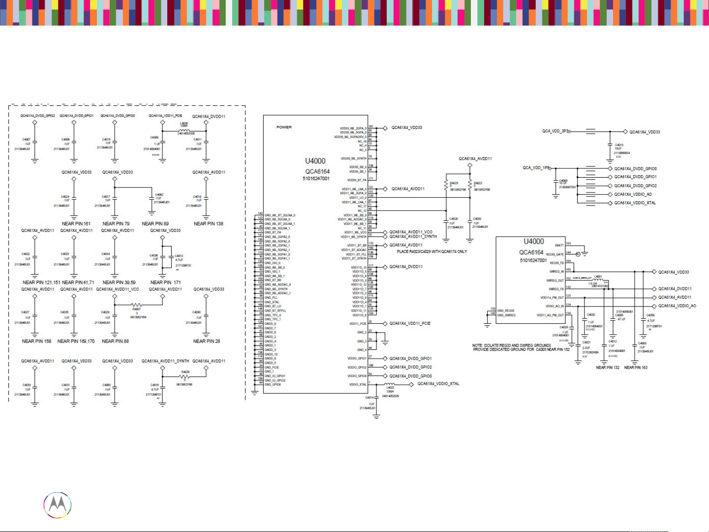
BT/WiFi – Schematic
Page 84
Sept 18, 2014
84
Page
Motorola Mobility Confidential Proprietary
BT/WiFi – Schematic (cont.)
Page 85

Sept 18, 2014
85
Page
Motorola Mobility Confidential Proprietary
BT/WiFi – Schematic (cont.)
Page 86

Sept 18, 2014
86
Page
Motorola Mobility Confidential Proprietary
Location on board
BT/WiFi – Schematic (cont.)
Page 87

Sept 18, 2014
87
Page
Motorola Mobility Confidential Proprietary
The WiFi is turned on via the test command “WLAN download test firmware”.
Even though it is called download test firmware, WLAN IC is actually off before
this test.
So if this test fails, please check all the power supplies: 3.3V, 1.8V and 1.1V.
They should be present. If not, please look at the possible problem with the
power management IC PMA8084 and 3.3V buck boost IC U2350.
Please also check the 48 MHz clock at the crystal Y4004.
The “WLAN module drain” is obtained by subtracting “WLAN Module Off
Current” from “WLAN Module On Current”.
There is a wide limit for “WLAN Module Off Current” from “WLAN Module On
Current”. But if you fail “WLAN module drain”, you should pay attention to these
2 values. If the “WLAN Module Off Current” is abnormally low, it might indicate
that there is a problem at somewhere else in the board.
BT/WiFi – WiFi Module Current Drain and MAC Address
Page 88

Sept 18, 2014
88
Page
Motorola Mobility Confidential Proprietary
If it fails either the TX power measurement or the current drain measurement, it
indicates that there is a problem with RF path starting from the IC to the antenna
connector. Please check the components along the path as highlighted below.
BT/WiFi – WiFi 2.4/5 GHz TX Power and Current Drain
Page 89

Sept 18, 2014
89
Page
Motorola Mobility Confidential Proprietary
Just connect the spectrum analyzer or power meter directly to J010 connector as
following:
The WiFi signal is 20 MHz wide. If you use a spectrum analyzer, you should pick
a wide enough span to measure the channel power across 20 MHz. Or if your
spectrum analyzer can support 20 MHz resolution bandwidth, you can just use
zero span.
BT/WiFi – Measure Power on Bench
Page 90

Sept 18, 2014
90
Page
Motorola Mobility Confidential Proprietary
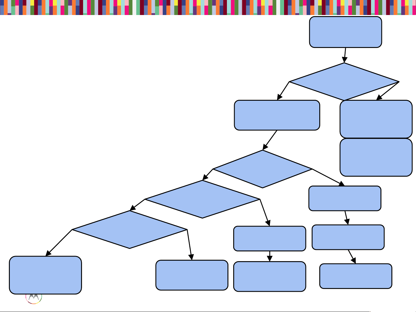
BT/WiFi – No Turn On Issue Analysis Procedure
Page 91

Sept 18, 2014
91
Page
Motorola Mobility Confidential Proprietary
Exposed(VIA(of(BT_EN
Exposed(VIA(of(WLAN_EN
BT/WiFi – No Turn On Issue Analysis Procedure (cont.)
Page 92

Sept 18, 2014
92
Page
Motorola Mobility Confidential Proprietary
NFC TROUBLESHOOTING
Page 93

Sept 18, 2014
93
Page
Motorola Mobility Confidential Proprietary
Here are the various test cases for NFC:
- NFC Antenna Self Test Status
- NFC Antenna SWP Line Test
- NFC Tag test
NFC
Page 94

Sept 18, 2014
94
Page
Motorola Mobility Confidential Proprietary
1. Verify NFC antenna exists, is connected, and verify it is properly seated.
NFC – Debugging Procedure
Page 95

Sept 18, 2014
95
Page
Motorola Mobility Confidential Proprietary
NFC – Debugging Procedure (cont.)
Page 96

Sept 18, 2014
96
Page
Motorola Mobility Confidential Proprietary
2. Verify NFC antenna connector is not damaged on flex or on PCB. There may
be soldering defects, such as shorts, broken pads. There may also be broken
pins within the connector. Often broken pins can occur through improper
insertion of connector.
3. Replace NFC antenna to see if it follows antenna itself.
4. Ensure NFC antenna matching components are not damaged.
NFC – Debugging Procedure (cont.)
Page 97

Sept 18, 2014
97
Page
Motorola Mobility Confidential Proprietary
NFC – Debugging Procedure (cont.)
Page 98

Sept 18, 2014
98
Page
Motorola Mobility Confidential Proprietary
NFC – Debugging Procedure (cont.)
Page 99

Sept 18, 2014
99
Page
Motorola Mobility Confidential Proprietary
NFC – Debugging Procedure
 Loading...