

Page 1

WiNG 5.7.1
ACCESS POINT
SYSTEM REFERENCE GUIDE
Page 2

Page 3

WING 5.7.1
ACCESS POINT
SYSTEM REFERENCE GUIDE
MN001977A01
Revision A
April 2015
Page 4

ii WiNG 5.7.1 Access Point System Reference Guide
Page 5

TABLE OF CONTENTS
About this Guide
Chapter 1, Overview
1.1 About the WiNG Software ...........................................................................................................................................1-2
Chapter 2, Web User Interface Features
2.1 Accessing the Web UI ..................................................................................................................................................2-2
2.1.1 Browser and System Requirements ...................................................................................................................2-2
2.1.2 Connecting to the Web UI ..................................................................................................................................2-2
2.2 Glossary of Icons Used .................................................................................................................................................2-4
2.2.1 Global Icons ........................................................................................................................................................2-4
2.2.2 Dialog Box Icons .................................................................................................................................................2-5
2.2.3 Table Icons ..........................................................................................................................................................2-5
2.2.4 Status Icons ........................................................................................................................................................2-6
2.2.5 Configurable Objects ..........................................................................................................................................2-6
2.2.6 Configuration Objects ....................................................................................................
2.2.7 Configuration Operation Icons ............................................................................................................................2-9
2.2.8 Access Type Icons .............................................................................................................................................2-10
2.2.9 Administrative Role Icons .................................................................................................................................2-10
2.2.10 Device Icons ....................................................................................................................................................2-11
.....................................2-9
Chapter 3, Quick Start
3.1 Using the Initial Setup Wizard .....................................................................................................................................3-2
3.1.1 Typical Setup Wizard ..........................................................................................................................................3-5
3.1.1.1 Virtual Controller AP Mode .......................................................................................................................3-8
3.1.1.2 Standalone Mode ......................................................................................................................................3-9
3.1.1.3 Network Topology Selection ...................................................................................................................3-10
3.1.1.4 LAN Configuration ...................................................................................................................................3-11
3.1.1.5 WAN Configuration .................................................................................................................................3-13
Page 6

2 WiNG 5.7.1 Access Point System Reference Guide
3.1.1.6 Wireless LAN Setup ................................................................................................................................3-15
3.1.1.7 Summary And Commit Screen ................................................................................................................3-19
3.1.1.8 Adopt to a controller ...............................................................................................................................3-20
3.1.2 Advanced Setup Wizard ...................................................................................................................................3-21
3.1.2.1 Network Topology Selection ...................................................................................................................3-24
3.1.2.2 LAN Configuration ...................................................................................................................................3-25
3.1.2.3 WAN Configuration .................................................................................................................................3-27
3.1.2.4 Radio Configuration ................................................................................................................................3-29
3.1.2.5 Wireless LAN Setup ................................................................................................................................3-31
3.1.2.6 System Information .................................................................................................................................3-33
3.1.2.7 Summary And Commit Screen ................................................................................................................3-34
3.1.2.8 Adopt to a controller ...............................................................................................................................3-35
Chapter 4, Dashboard
4.1 Dashboard .....................................................................................................................................................................4-2
4.1.1 Dashboard Conventions ......................................................................................................................................4-2
4.1.1.1 Health ........................................................................................................................................................4-3
4.1.1.2 Inventory ....................................................................................................................................................4-7
4.2 Network View .............................................................................................................................................................4-10
4.2.1 Network View Display Options ........................................................................................................................4-11
4.2.2 Device Specific Information ..............................................................................................................................4-12
Chapter 5, Device Configuration
5.1 RF Domain Configuration ..............................................................................................................................................5-2
5.1.1 RF Domain Sensor Configuration ........................................................................................................................5-3
5.1.2 RF Client Name Configuration ............................................................................................................................5-4
5.1.3 RF Domain Alias Configuration ...........................................................................................................................5-5
5.1.3.1 Network Basic Alias ..................................................................................................................................5-7
5.1.3.2 Network Group Alias ...............................................................................................................................5-10
5.1.3.3 Network Service Alias ............................................................................................................................5-12
5.2 System Profile Configuration ......................................................................................................................................5-14
5.2.1 General Profile Configuration ...........................................................................................................................5-15
5.2.2 Profile Radio Power ..........................................................................................................................................5-16
5.2.3 Profile Adoption (Auto Provisioning) Configuration .......................................................................
5.2.4 Profile Wired 802.1X Configuration ..................................................................................................................5-20
5.2.5 Profile Interface Configuration .........................................................................................................................5-21
5.2.5.1 Ethernet Port Configuration ....................................................................................................................5-22
5.2.5.2 Virtual Interface Configuration ...............................................................................................................5-31
5.2.5.3 Port Channel Configuration .....................................................................................................................5-41
5.2.5.4 Access Point Radio Configuration ...........................................................................................................5-48
5.2.5.5 WAN Backhaul Configuration .................................................................................................................5-60
5.2.5.6 PPPoE Configuration ................................................................................................................................5-63
5.2.6 Profile Network Configuration ..........................................................................................................................5-66
5.2.6.1 DNS Configuration ..................................................................................................................................5-67
5.2.6.2 ARP ..........................................................................................................................................................5-68
...................5-18
Page 7

Table of Contents 3
5.2.6.3 L2TPv3 Profile Configuration ...................................................................................................................5-70
5.2.6.4 IGMP Snooping .......................................................................................................................................5-80
5.2.6.5 MLD Snooping .........................................................................................................................................5-82
5.2.6.6 Quality of Service (QoS) ..........................................................................................................................5-84
5.2.6.7 Spanning Tree Configuration ..................................................................................................................5-86
5.2.6.8 Routing ....................................................................................................................................................5-89
5.2.6.9 Dynamic Routing (OSPF) ..........................................................................................................................5-92
5.2.6.10 Forwarding Database ..........................................................................................................................5-106
5.2.6.11 Bridge VLAN ........................................................................................................................................5-108
5.2.6.12 Cisco Discovery Protocol Configuration ..............................................................................................5-116
5.2.6.13 Link Layer Discovery Protocol Configuration ......................................................................................5-117
5.2.6.14 Miscellaneous Network Configuration ...............................................................................................5-118
5.2.6.15 Alias ....................................................................................................................................................5-119
5.2.6.16 Profile Network Configuration and Deployment Considerations .......................................................5-127
5.2.7 Profile Security Configuration .........................................................................................................................5-128
5.2.7.1 Defining Profile VPN Settings ...............................................................................................................5-129
5.2.7.2 Defining Profile Auto IPSec Tunnel .......................................................................................................5-144
5.2.7.3 Defining Profile Security Settings .........................................................................................................5-145
5.2.7.4 Setting the Certificate Revocation List (CRL) Configuration .................................................................5-147
5.2.7.5 Setting the Profile’s NAT Configuration ...............................................................................................5-148
5.2.7.6 Setting the Profile’s Bridge NAT Configuration ....................................................................................5-156
5.2.7.7 Profile Security Configuration and Deployment Considerations ..........................................................5-158
5.2.8 Virtual Router Redundancy Protocol (VRRP) Configuration ............................................................................5-159
5.2.9 Profile Critical Resources ................................................................................................................................5-162
5.2.10 Profile Services Configuration ......................................................................................................................5-166
5.2.10.1 Profile Services Configuration and Deployment Considerations ........................................................5-167
5.2.11 Profile Management Configuration ..............................................................................................................5-168
5.2.11.1 Upgrading AP6532 Firmware from 5.1 ................................................................................................5-171
5.2.11.2 Profile Management Configuration and Deployment Considerations ................................................5-172
5.2.12 Mesh Point Configuration .............................................................................................................................5-172
5.2.12.1 Vehicle Mounted Modem (VMM) Deployment Consideration ...........................................................5-180
5.2.13 Advanced Profile Configuration ....................................................................................................................5-181
5.2.13.1 Advanced Profile Client Load Balancing .............................................................................................5-181
5.2.13.2 Configuring MINT Protocol .................................................................................................................5-186
5.2.13.3 Advanced Profile Miscellaneous Configuration .................................................................................5-191
5.2.14 Environmental Sensor Configuration ............................................................................................................5-192
5.3 Managing Virtual Controllers ...................................................................................................................................5-194
5.4 Overriding a Device Configuration ...........................................................................................................................5-196
5.4.1 Basic Configuration .........................................................................................................................................5-196
5.4.2 Certificate Management .................................................................................................................................5-198
5.4.2.1 Manage Certificates .............................................................................................................................5-200
5.4.3 RF Domain Overrides ......................................................................................................................................5-213
5.4.4 Wired 802.1X Overrides ..................................................................................................................................5-215
5.4.5 Device Overrides .............................................................................................................................................5-216
5.4.5.1 Radio Power Overrides ..........................................................................................................................5-219
5.4.5.2 Adoption Overrides ...............................................................................................................................5-221
5.4.5.3 Profile Interface Override Configuration ...............................................................................
................5-224
Page 8

4 WiNG 5.7.1 Access Point System Reference Guide
5.4.5.4 Overriding the Network Configuration ..................................................................................................5-267
5.4.5.5 Overriding a Security Configuration ......................................................................................................5-326
5.4.5.6 Overriding the Virtual Router Redundancy Protocol (VRRP) Configuration ..........................................5-348
5.4.5.7 Profile Critical Resources ......................................................................................................................5-353
5.4.5.8 Overriding a Services Configuration .....................................................................................................5-356
5.4.5.9 Overriding a Management Configuration .............................................................................................5-357
5.4.5.10 Overriding Mesh Point Configuration .................................................................................................5-361
5.4.5.11 Overriding an Advanced Configuration ...............................................................................................5-370
5.4.5.12 Overriding Environmental Sensor Configuration ................................................................................5-383
5.5 Managing an Event Policy ........................................................................................................................................5-385
Chapter 6, Wireless Configuration
6.1 Wireless LANs ..............................................................................................................................................................6-3
6.1.1 Configuring WLAN Basic Configuration ............................................................................................................. 6-5
6.1.1.1 WLAN Basic Configuration Deployment Considerations .........................................................................6-7
6.1.2 Configuring WLAN Security Settings .................................................................................................................6-8
6.1.2.1 802.1x EAP, EAP-PSK and EAP MAC ........................................................................................................6-9
6.1.2.2 MAC Authentication ...............................................................................................................................6-11
6.1.2.3 PSK / None ..............................................................................................................................................6-12
6.1.2.4 Captive Portal ..........................................................................................................................................6-12
6.1.2.5 Passpoint Policy ......................................................................................................................................6-13
6.1.2.6 MAC Registration ....................................................................................................................................6-13
6.1.2.7 External Controller ..................................................................................................................................6-14
6.1.2.8 TKIP-CCMP ..............................................................................................................................................6-14
6.2 TKIP-CCMP Deployment Considerations ....................................................................................................................6-18
6.2.0.1 WPA2-CCMP ...........................................................................................................................................6-18
6.2.0.2 WEP 64 ....................................................................................................................................................6-21
6.2.0.3 WEP 128.................................................................................................................................................. 6-23
6.2.0.4 Keyguard ................................................................................................................................................. 6-25
6.2.1 Configuring WLAN Firewall Settings ...............................................................................................................6-26
6.2.2 Configuring WLAN Client Settings ...................................................................................................................6-37
6.2.3 Configuring WLAN Accounting Settings ..........................................................................................................6-39
6.2.4 Configuring WLAN Service Monitoring Settings .............................................................................................6-41
6.2.5 Configuring WLAN Client Load Balancing Settings .........................................................................................6-43
6.2.6 Configuring WLAN Advanced Settings ............................................................................................................6-46
6.2.7 Configuring Auto Shutdown Settings ...............................................................................................................6-51
6.3 WLAN QoS Policy .......................................................................................................................................................6-54
6.3.1 Configuring QoS WMM Settings ......................................................................................................................6-56
6.3.2 Configuring a WLAN’s QoS Rate Limit Settings ..............................................................................................6-60
6.3.3 Configuring Multimedia Optimizations .............................................................................................................6-65
6.3.3.1 WLAN QoS Deployment Considerations ................................................................................................6-67
6.4 Radio QoS Policy .........................................................................................................................................................6-68
6.4.1 Configuring a Radio’s QoS Policy .....................................................................................................................6-69
6.5 Association ACL ..........................................................................................................................................................6-79
6.5.1 Association ACL Deployment Considerations ..................................................................................................6-81
6.6 SMART RF ...................................................................................................................................................................6-82
Page 9

Table of Contents 5
6.6.1 Smart RF Configuration and Deployment Considerations ................................................................................6-92
6.7 MeshConnex Policy ....................................................................................................................................................6-93
6.8 Mesh QoS Policy .......................................................................................................................................................6-100
6.9 Passpoint Policy ........................................................................................................................................................6-107
Chapter 7, Network Configuration
7.1 Policy Based Routing (PBR) ...........................................................................................................................................7-2
7.2 L2TP V3 Configuration ..................................................................................................................................................7-8
7.3 Crypto CMP Policy ......................................................................................................................................................7-12
7.4 AAA Policy ..................................................................................................................................................................7-15
7.5 AAA TACACS Policy ...................................................................................................................................................7-26
7.6 Alias ............................................................................................................................................................................7-34
7.6.1 Network Basic Alias .........................................................................................................................................7-34
7.6.2 Network Group Alias ........................................................................................................................................7-37
7.6.3 Network Service Alias ......................................................................................................................................7-40
7.7 IPv6 Router Advertisement Policy ..............................................................................................................................7-42
7.8 Network Deployment Considerations ........................................................................................................................7-45
Chapter 8, Security Configuration
8.1 Wireless Firewall ..........................................................................................................................................................8-2
8.1.1 Defining a Firewall Configuration .......................................................................................................................8-2
8.2 Configuring IP Firewall Rules .....................................................................................................................................8-16
8.2.1 Setting an IPv4 or IPv6 Firewall Policy .............................................................................................................8-16
8.2.2 Setting an IP SNMP ACL Policy ........................................................................................................................8-20
8.3 Device Fingerprinting ..................................................................................................................................................8-23
8.4 Configuring MAC Firewall Rules ................................................................................................................................ 8-30
8.5 Wireless IPS (WIPS) ...................................................................................................................................................8-33
8.6 Device Categorization .................................................................................................................................................8-42
8.7 Security Deployment Considerations .........................................................................................................................8-44
Chapter 9, Services Configuration
9.1 Configuring Captive Portal Policies ..............................................................................................................................9-2
9.1.1 Configuring a Captive Portal Policy ....................................................................................................................9-2
9.2 Setting the DNS Whitelist Configuration ...................................................................................................................9-13
9.3 Setting the DHCP Server Configuration .....................................................................................................................9-14
9.3.1 Defining DHCP Pools .........................................................................................................................................9-14
9.3.2 Defining DHCP Server Global Settings .............................................................................................................9-22
9.3.3 DHCP Class Policy Configuration ......................................................................................................................9-24
9.3.4 DHCP Deployment Considerations ...................................................................................................................9-26
9.4 Setting the Bonjour Gateway Configuration ..............................................................................................................9-27
9.4.1 Configuring the Bonjour Discovery Policy .........................................................................................................9-27
9.4.2 Configuring the Bonjour Forwarding Policy ......................................................................................................9-29
9.5 Setting the DHCPv6 Server Policy ..............................................................................................................................9-32
9.5.1 Defining DHCPv6 Options .................................................................................................................................9-33
Page 10

6 WiNG 5.7.1 Access Point System Reference Guide
9.5.2 DHCPv6 Pool Configuration ..............................................................................................................................9-34
9.6 Setting the RADIUS Configuration .............................................................................................................................9-38
9.6.1 Creating RADIUS Groups ..................................................................................................................................9-38
9.6.1.1 Creating RADIUS Groups ........................................................................................................................9-41
9.6.2 Defining User Pools ..........................................................................................................................................9-43
9.6.3 Configuring the RADIUS Server ........................................................................................................................9-48
9.7 Services Deployment Considerations .........................................................................................................................9-56
Chapter 10, Management Access
10.1 Creating Administrators and Roles .........................................................................................................................10-2
10.2 Setting the Access Control Configuration ................................................................................................................10-5
10.3 Setting the Authentication Configuration ................................................................................................................10-8
10.4 Setting the SNMP Configuration ............................................................................................................................10-10
10.5 SNMP Trap Configuration ......................................................................................................................................10-12
10.6 Management Access Deployment Considerations ................................................................................................10-14
Chapter 11, Diagnostics
11.1 Fault Management ...................................................................................................................................................11-2
11.2 Crash Files ................................................................................................................................................................11-6
11.3 Advanced ..................................................................................................................................................................11-7
11.3.1 UI Debugging ..................................................................................................................................................11-7
11.3.2 View UI Logs ...................................................................................................................................................11-8
11.3.3 View Sessions .................................................................................................................................................11-9
Chapter 12, Operations
12.1 Devices .....................................................................................................................................................................12-2
12.1.1 Managing Firmware and Configuration Files .................................................................................................12-2
12.1.1.1 Managing Running Configuration .........................................................................................................12-3
12.1.1.2 Managing Startup Configuration ..........................................................................................................12-6
12.1.2 Rebooting the Device ......................................................................................................................................12-8
12.1.3 Managing Crypto CMP Certificates ..............................................................................................................12-10
12.1.4 Upgrading Device Firmware .........................................................................................................................12-11
12.1.5 Troubleshooting the Device ..........................................................................................................................12-13
12.1.5.1 Managing Crash Dump Files ...............................................................................................................12-13
12.1.5.2 Copy Crash Info ...................................................................................................................................12-15
12.1.5.3 Copy Tech Support Dump ....................................................................................................................12-17
12.1.5.4 Locating a Device ................................................................................................................................12-19
12.1.5.5 Debugging Wireless Clients ...............................................................................................................12-20
12.1.5.6 Packet Capture ....................................................................................................................................12-22
12.1.6 Viewing Device Summary Information .........................................................................................................12-25
12.1.7 Adopted Device Upgrades ............................................................................................................................12-27
12.1.8 File Management ..........................................................................................................................................12-34
12.1.9 Adopted Device Restart ................................................................................................................................12-40
12.1.10 Captive Portal Pages ...................................................................................................................................12-41
Page 11

Table of Contents 7
12.1.11 Managing Crypto CMP Certificates ............................................................................................................12-46
12.1.12 Re-elect Controller ......................................................................................................................................12-47
12.2 Certificates .............................................................................................................................................................12-49
12.2.1 Certificate Management ...............................................................................................................................12-49
12.2.2 RSA Key Management ..................................................................................................................................12-54
12.2.3 Certificate Creation .......................................................................................................................................12-59
12.2.4 Generating a Certificate Signing Request (CSR) ..........................................................................................12-61
12.3 Smart RF .................................................................................................................................................................12-64
12.3.1 Managing Smart RF for a RF Domain ...........................................................................................................12-64
12.4 Operations Deployment Considerations .................................................................................................................12-67
Chapter 13, Statistics
13.1 System Statistics .....................................................................................................................................................13-2
13.1.1 Health ..............................................................................................................................................................13-2
13.1.2 Inventory .........................................................................................................................................................13-4
13.1.3 Adopted Devices .............................................................................................................................................13-5
13.1.4 Pending Adoptions ..........................................................................................................................................13-7
13.1.5 Offline Devices ................................................................................................................................................13-8
13.1.6 Device Upgrade ...............................................................................................................................................13-9
13.1.7 Licenses ........................................................................................................................................................13-10
13.1.8 WIPS Summary .............................................................................................................................................13-14
13.2 RF Domain Statistics ..............................................................................................................................................13-16
13.2.1 Health ............................................................................................................................................................13-16
13.2.2 Inventory .......................................................................................................................................................13-19
13.2.3 Devices ..........................................................................................................................................................13-21
13.2.4 AP Detection .................................................................................................................................................13-22
13.2.5 Wireless Clients ............................................................................................................................................13-23
13.2.6 Device Upgrade .............................................................................................................................................13-25
13.2.7 Wireless LANs ..............................................................................................................................................13-26
13.2.8 Radios ...........................................................................................................................................................13-28
13.2.8.1 Status ..................................................................................................................................................13-28
13.2.8.2 RF Statistics ........................................................................................................................................13-29
13.2.8.3 Traffic Statistics ..................................................................................................................................13-30
13.2.9 Mesh .............................................................................................................................................................13-32
13.2.10 Mesh Point ..................................................................................................................................................13-32
13.2.11 SMART RF ...................................................................................................................................................13-47
13.2.12 WIPS ...........................................................................................................................................................13-52
13.2.12.1 WIPS Client Blacklist ........................................................................................................................13-52
13.2.12.2 WIPS Events ......................................................................................................................................13-53
13.2.13 Captive Portal ..............................................................................................................................................13-54
13.3 Access Point Statistics ...........................................................................................................................................13-56
13.3.1 Health ............................................................................................................................................................13-57
13.3.2 Device ...........................................................................................................................................................13-59
13.3.3 Web-Filtering ................................................................................................................................................13-62
13.3.4 Device Upgrade .............................................................................................................................................13-64
13.3.5 Adoption ........................................................................................................................................................13-65
Page 12

8 WiNG 5.7.1 Access Point System Reference Guide
13.3.5.1 Adopted APs ........................................................................................................................................13-65
13.3.5.2 AP Adoption History ............................................................................................................................13-66
13.3.5.3 AP Self Adoption History ....................................................................................................................13-67
13.3.5.4 Pending Adoptions ..............................................................................................................................13-67
13.3.6 AP Detection .................................................................................................................................................13-69
13.3.7 Wireless Clients ............................................................................................................................................13-71
13.3.8 Wireless LANs ..............................................................................................................................................13-73
13.3.9 Policy Based Routing ....................................................................................................................................13-75
13.3.10 Radios .........................................................................................................................................................13-77
13.3.10.1 Status ................................................................................................................................................13-77
13.3.10.2 RF Statistics ......................................................................................................................................13-78
13.3.10.3 Traffic Statistics ................................................................................................................................13-80
13.3.11 Mesh ...........................................................................................................................................................13-82
13.3.12 Interfaces ....................................................................................................................................................13-83
13.3.12.1 General Interface Details ..................................................................................................................13-84
13.3.12.2 IPv6 Address ......................................................................................................................................13-87
13.3.12.3 Multicast Groups Joined ...................................................................................................................13-90
13.3.12.4 Network Graph ..................................................................................................................................13-92
13.3.13 RTLS ............................................................................................................................................................13-93
13.3.14 PPPoE ..........................................................................................................................................................13-95
13.3.15 OSPF ............................................................................................................................................................13-97
13.3.15.1 OSPF Summary ..................................................................................................................................13-98
13.3.15.2 OSPF Neighbors ..............................................................................................................................13-100
13.3.15.3 OSPF Area Details ...........................................................................................................................13-101
13.3.15.4 OSPF Route Statistics .....................................................................................................................13-103
13.3.15.5 OSPF Interface .................................................................................................................................13-106
13.3.15.6 OSPF State ......................................................................................................................................13-107
13.3.16 L2TPv3 Tunnels .........................................................................................................................................13-109
13.3.17 VRRP ..........................................................................................................................................................13-111
13.3.18 Critical Resources .....................................................................................................................................13-113
13.3.19 LDAP Agent Status ...................................................................................................................................13-115
13.3.20 Guest Users ...............................................................................................................................................13-117
13.3.21 GRE Tunnels ..............................................................................................................................................13-119
13.3.22 Dot1x .........................................................................................................................................................13-121
13.3.23 Network ....................................................................................................................................................13-123
13.3.23.1 ARP Entries ......................................................................................................................................13-123
13.3.23.2 Route Entries ...................................................................................................................................13-124
13.3.23.3 Default Routes ................................................................................................................................13-125
13.3.23.4 Bridge ..............................................................................................................................................13-127
13.3.23.5 IGMP ................................................................................................................................................13-129
13.3.23.6 MLD .................................................................................................................................................13-130
13.3.23.7 DHCP Options .................................................................................................................................13-132
13.3.23.8 Cisco Discovery Protocol ............................................................................................
13.3.23.9 Link Layer Discovery Protocol ........................................................................................................13-134
13.3.23.10 IPv6 Neighbor ...............................................................................................................................13-135
13.3.23.11 MSTP .............................................................................................................................................13-138
13.3.23.12 DHCPv6 Relay & Client .................................................................................................................13-140
....................13-133
Page 13

Table of Contents 9
13.3.24 DHCP Server ..............................................................................................................................................13-141
13.3.24.1 DHCP Server General Information ..................................................................................................13-141
13.3.24.2 DHCP Server Bindings .....................................................................................................................13-143
13.3.24.3 DHCP Server Networks ...................................................................................................................13-143
13.3.25 Firewall .....................................................................................................................................................13-145
13.3.25.1 Packet Flows ...................................................................................................................................13-145
13.3.25.2 Denial of Service .............................................................................................................................13-146
13.3.25.3 IP Firewall Rules .............................................................................................................................13-147
13.3.25.4 IPv6 Firewall Rules .........................................................................................................................13-148
13.3.25.5 MAC Firewall Rules .......................................................................................................................13-149
13.3.25.6 NAT Translations ............................................................................................................................13-150
13.3.25.7 DHCP Snooping ...............................................................................................................................13-151
13.3.25.8 IPv6 Neighbor Snooping ..................................................................................................................13-153
13.3.26 VPN ...........................................................................................................................................................13-155
13.3.26.1 IKESA ...............................................................................................................................................13-155
13.3.26.2 IPSec ................................................................................................................................................13-156
13.3.27 Certificates ................................................................................................................................................13-158
13.3.27.1 Trustpoints ......................................................................................................................................13-158
13.3.27.2 RSA Keys ........................................................................................................................................13-160
13.3.28 WIPS .........................................................................................................................................................13-162
13.3.28.1 WIPS Client Blacklist ......................................................................................................................13-162
13.3.28.2 WIPS Events ....................................................................................................................................13-163
13.3.29 Sensor Servers ..........................................................................................................................................13-165
13.3.30 Bonjour Services .......................................................................................................................................13-166
13.3.31 Captive Portal ............................................................................................................................................13-168
13.3.32 Network Time ...........................................................................................................................................13-170
13.3.32.1 NTP Status ......................................................................................................................................13-170
13.3.32.2 NTP Association ..............................................................................................................................13-171
13.3.33 Load Balancing ..........................................................................................................................................13-172
13.3.34 Environmental Sensors (AP8132 Models Only) ........................................................................................13-174
13.4 Wireless Client Statistics .....................................................................................................................................13-178
13.4.1 Health ..........................................................................................................................................................13-178
13.4.2 Details .........................................................................................................................................................13-181
13.4.3 Traffic ..........................................................................................................................................................13-184
13.4.4 WMM TSPEC ..............................................................................................................................................13-187
13.4.5 Association History .....................................................................................................................................13-188
13.4.6 Graph ...........................................................................................................................................................13-189
Chapter 14, WiNG Events
14.1 Event History Messages ...........................................................................................................................................14-2
Page 14

10 WiNG 5.7.1 Access Point System Reference Guide
Appendix A, Customer Support
Appendix B, Publicly Available Software
B.1 General Information .................................................................................................................................................... B-1
B.2 Open Source Software Used ....................................................................................................................................... B-1
B.3 OSS Licenses ............................................................................................................................................................ B-10
B.3.1 Apache License, Version 2.0 ........................................................................................................................... B-10
B.3.2 The BSD License .............................................................................................................................................. B-12
B.3.3 Creative Commons Attribution-ShareAlike License, version 3.0 .................................................................... B-12
B.3.4 DropBear License ............................................................................................................................................. B-17
B.3.5 GNU General Public License, version 2 ........................................................................................................... B-18
B.3.6 GNU Lesser General Public License 2.1 .......................................................................................................... B-22
B.3.7 GNU General Public License, version 3 ........................................................................................................... B-27
B.3.8 ISC License ...................................................................................................................................................... B-35
B.3.9 GNU Lesser General Public License, version 3.0 ............................................................................................ B-35
B.3.10 GNU General Public License 2.0 .................................................................................................................... B-37
B.3.11 GNU Lesser General Public License, version 2.0 .......................................................................................... B-42
B.3.12 GNU Lesser General Public License, version 2.1 .......................................................................................... B-47
B.3.13 MIT License ................................................................................................................................................... B-52
B.3.14 Mozilla Public License, version 2 .................................................................................................................. B-53
B.3.15 The Open LDAP Public License ...................................................................................................................... B-57
B.3.16 OpenSSL License ........................................................................................................................................... B-57
B.3.17 WU-FTPD Software License .......................................................................................................................... B-58
B.3.18 zlib License .................................................................................................................................................... B-59
Page 15

ABOUT THIS GUIDE
This manual supports the following access points:
• Access Points – AP621, AP622, AP650, AP6511, AP6521, AP6522, AP6522M, AP6532, AP6562, AP7131, AP7161, AP7181,
AP7502, AP7522, AP7532, AP7562, AP8122, AP8132, AP8163, AP8222, AP8232 and ES6510.
NOTE: In this guide:
• AP6511, AP6521, AP6522, AP6522M, AP6532 and AP6562 are collectively represented as AP65XX.
• AP7131, AP7161 and AP7181 are collectively represented as AP71XX.
• AP7502, AP7522, AP7532 and AP7562 are collectively represented as AP75XX.
• AP8122, AP8132 and AP8163 are collectively represented as AP81XX.
• AP8222 and AP8232 are collectively represented as AP82XX.
NOTE: ES6510 is an Ethernet Switch managed by a wireless controller such as RFS4000/RFS6000/
RFS7000/NX4500/NX4524/NX6500/NX6524/NX7500/NX7510/NX7520/NX7530/NX9000/NX9500/
NX9510. ES6510 does not have radios and does not provide WLAN support.
This section is organized into the following:
• Document Convention
• Notational Conventions
• Symbol Technologies End-User Software License Agreement
Page 16

2 WiNG 5.7.1 Access Point System Reference Guide
Document Convention
The following conventions are used in this document to draw your attention to important information:
NOTE: Indicates tips or special requirements.
CAUTION: Indicates conditions that can cause equipment damage or data loss.
!
WARNING! Indicates a condition or procedure that could result in personal
injury or equipment damage.
Switch Note: Indicates caveats unique to a RFS4000, RFS6000, RFS7000, NX4500,
NX4524, NX6500, NX6524, NX9000, NX9500 or NX9510 model controller or service
platform.
Notational Conventions
The following notational conventions are used in this document:
• Italics are used to highlight specific items in the general text, and to identify chapters and sections in this and related
documents
• Bullets (•) indicate:
• lists of alternatives
• lists of required steps that are not necessarily sequential
• action items
• Sequential lists (those describing step-by-step procedures) appear as numbered lists
Page 17

About this Guide 3
Symbol Technologies
End-User Software License Agreement
THIS SYMBOL TECHNOLOGIES END-USER SOFTWARE LICENSE AGREEMENT (“END-USER LICENSE AGREEMENT”) IS
BETWEEN SYMBOL TECHNOLOGIES INC. (HEREIN “SYMBOL TECHNOLOGIES”) AND END-USER CUSTOMER TO WHOM
SYMBOL TECHNOLOGIES’ PROPRIETARY SOFTWARE OR SYMBOL TECHNOLOGIES PRODUCTS CONTAINING EMBEDDED,
PRE-LOADED, OR INSTALLED SOFTWARE (“PRODUCTS”) IS MADE AVAILABLE. THIS END-USER LICENSE AGREEMENT
CONTAINS THE TERMS AND CONDITIONS OF THE LICENSE SYMBOL TECHNOLOGIES IS PROVIDING TO END-USER
CUSTOMER, AND END-USER CUSTOMER’S USE OF THE SOFTWARE AND DOCUMENTATION. BY USING, DOWNLOADING OR
INSTALLING THIS SOFTWARE, YOU OR THE ENTITY THAT YOU REPRESENT (“END-USER CUSTOMER”) ARE CONSENTING TO
BE BOUND BY AND ARE BECOMING A PARTY TO THIS END-USER LICENSE AGREEMENT.
1. DEFINITIONS
“Documentation” means product and software documentation that specifies technical and performance features and
capabilities, and the user, operation and training manuals for the Software (including all physical or electronic media upon
which such information is provided).
“Open Source Software” means software with either freely obtainable source code license for modification, or permission
for free distribution.
“Open Source Software License” means the terms or conditions under which the Open Source Software is licensed.
“Software” (i) means proprietary software in object code format, and adaptations, translations, decompilations,
disassemblies, emulations, or derivative works of such software; (ii) means any modifications, enhancements, new versions
and new releases of the software provided by Symbol Technologies; and (iii) may contain items of software owned by a
third party supplier. The term “Software” does not include any third party software provided under separate license or third
party software not licensable under the terms of this Agreement. To the extent, if any, that there is a separate license
agreement packaged with, or provided electronically with, a particular Product that becomes effective on an act of
acceptance by the end user, then that agreement supersedes this End-User License Agreement as to the end use of that
particular Product.
2. GRANT OF LICENSE
2.1 Subject to the provisions of this End-User License Agreement, Symbol Technologies grants to End-User Customer a
personal, limited, non-transferable (except as provided in Section 4), and non-exclusive license under Symbol
Technologies’ copyrights and confidential information embodied in the Software to use the Software, in object code
form, and the Documentation solely in connection with End-User Customer’s use of the Products. This End-User License
Agreement does not grant any rights to source code.
2.2 If the Software licensed under this End-User License Agreement contains or is derived from Open Source Software, the
terms and conditions governing the use of such Open Source Software are in the Open Source Software Licenses of the
copyright owner and not this End-User License Agreement. If there is a conflict between the terms and conditions of
this End-User License Agreement and the terms and conditions of the Open Source Software Licenses governing EndUser Customer’s use of the Open Source Software, the terms and conditions of the license grant of the applicable Open
Source Software Licenses will take precedence over the license grants in this End-User License Agreement. If requested
by End-User Customer, Symbol Technologies will use commercially reasonable efforts to: (i) determine whether any
Open source Software is provided under this End-User License Agreement; (ii) identify the Open Source Software and
provide End-User Customer a copy of the applicable Open Source Software License (or specify where that license may
be found); and, (iii) provide End-User Customer a copy of the Open Source Software source code, without charge, if it is
publicly available (although distribution fees may be applicable).
3. LIMITATIONS ON USE
3.1 End-User Customer may use the Software only for End-User Customer’s internal business purposes and only in
accordance with the Documentation. Any other use of the Software is strictly prohibited and will be deemed a breach
of this End-User License Agreement. Without limiting the general nature of these restrictions, End-User Customer will
Page 18

4 WiNG 5.7.1 Access Point System Reference Guide
not make the Software available for use by third parties on a “time sharing,” “application service provider,” or “service
bureau” basis or for any other similar commercial rental or sharing arrangement.
3.2 End-User Customer will not, and will not allow or enable any third party to: (i) reverse engineer, disassemble, peel
components, decompile, reprogram or otherwise reduce the Software or any portion to a human perceptible form or
otherwise attempt to recreate the source code; (ii) modify, adapt, create derivative works of, or merge the Software with
other software; (iii) copy, reproduce, distribute, lend, or lease the Software or Documentation to any third party, grant
any sublicense or other rights in the Software or Documentation to any third party, or take any action that would cause
the Software or Documentation to be placed in the public domain; (iv) remove, or in any way alter or obscure, any
copyright notice or other notice of Symbol Technologies’ proprietary rights; (v) provide, copy, transmit, disclose, divulge
or make the Software or Documentation available to, or permit the use of the Software by any third party or on any
machine except as expressly authorized by this Agreement; or (vi) use, or permit the use of, the Software in a manner
that would result in the production of a copy of the Software solely by activating a machine containing the Software.
End-User Customer may make one copy of Software to be used solely for archival, back-up, or disaster recovery
purposes; provided that End-User Customer may not operate that copy of the Software at the same time as the original
Software is being operated. End-User Customer may make as many copies of the Documentation as it may reasonably
require for the internal use of the Software.
3.3 Unless otherwise authorized by Symbol Technologies in writing, End-User Customer will not, and will not enable or
allow any third party to: (i) install a licensed copy of the Software on more than one unit of a Product; or (ii) copy onto
or transfer Software installed in one unit of a Product onto another device.
3.4 If End-User Customer is purchasing Products that require a site license, End-User Customer must purchase a copy of the
applicable Software for each site at which End-User Customer uses such Software. End-User Customer may make one
additional copy for each computer owned or controlled by End-User Customer at each such site. End-User Customer may
temporarily use the Software on portable or laptop computers at other sites. End-User Customer must provide a written
list of all sites where End-User Customer uses or intends to use the Software.
4. TRANSFERS
4.1 End-User Customer will not transfer the Software or Documentation to any third party without Symbol Technologies’
prior written consent. Symbol Technologies’ consent may be withheld at its discretion and may be conditioned upon
transferee paying all applicable license fees and agreeing to be bound by this End-User License Agreement.
5. OWNERSHIP AND TITLE
5.1 Symbol Technologies, its licensors, and its suppliers retain all of their proprietary rights in any form in and to the
Software and Documentation, including, but not limited to, all rights in patents, patent applications, inventions,
copyrights, trademarks, trade secrets, trade names, and other proprietary rights in or relating to the Software and
Documentation. No rights are granted to End-User Customer under this Agreement by implication, estoppel or
otherwise, except for those rights which are expressly granted to End-User Customer in this End-User License
Agreement. All intellectual property developed, originated, or prepared by Symbol Technologies in connection with
providing the Software, Products, Documentation or related services remains vested exclusively in Symbol
Technologies, and End-User Customer will not have any shared development or other intellectual property rights.
6. CONFIDENTIALITY
6.1 End-User Customer acknowledges that the Software contains valuable proprietary information and trade secrets and
that unauthorized dissemination, distribution, modification, reverse engineering, disassembly or other improper use of
the Software will result in irreparable harm to Symbol Technologies for which monetary damages would be inadequate.
Accordingly, End-User Customer will limit access to the Software to those of its employees and agents who need to use
the Software for End-User Customer’s internal business.
7. MAINTENANCE AND SUPPORT
7.1 No maintenance or support is provided under this End-User License Agreement. Maintenance or support, if available,
will be provided under a separate Symbol Technologies Software maintenance and support agreement.
Page 19

About this Guide 5
8. LIMITED WARRANTY AND LIMITATION OF LIABILITY
8.1 Unless otherwise specified in the applicable warranty statement, the Documentation or in any other media at the time
of shipment of the Software by Symbol Technologies, and for the warranty period specified therein, for the first 120
days after initial shipment of the Software to the End-User Customer, Symbol Technologies warrants that the Software,
when installed and/or used properly, will be free from reproducible defects that materially vary from its published
specifications. Symbol Technologies does not warrant that End-User Customer’s use of the Software or the Products will
be uninterrupted or error-free or that the Software or the Products will meet End-User Customer’s particular
requirements.
8.2 SYMBOL TECHNOLOGIES’ TOTAL LIABILITY, AND END-USER CUSTOMER’S SOLE REMEDY, FOR ANY BREACH OF THIS
WARRANTY WILL BE LIMITED TO, AT SYMBOL TECHNOLOGIES’ OPTION, REPAIR OR REPLACEMENT OF THE
SOFTWARE OR PAYMENT OF END-USER CUSTOMER’S ACTUAL DAMAGES UP TO THE AMOUNT PAID TO SYMBOL
TECHNOLOGIES FOR THE SOFTWARE OR THE INDIVIDUAL PRODUCT IN WHICH THE SOFTWARE IS EMBEDDED OR FOR
WHICH IT WAS PROVIDED. THIS WARRANTY EXTENDS ONLY TO THE FIRST END-USER CUSTOMER; SUBSEQUENT
TRANSFEREES MUST ACCEPT THE SOFTWARE “AS IS” AND WITH NO WARRANTIES OF ANY KIND. SYMBOL
TECHNOLOGIES DISCLAIMS ALL OTHER WARRANTIES, EXPRESS OR IMPLIED, INCLUDING THE IMPLIED WARRANTIES
OF MERCHANTABILITY, NON-INFRINGEMENT, AND FITNESS FOR A PARTICULAR PURPOSE.
8.3 IN NO EVENT WILL SYMBOL TECHNOLOGIES BE LIABLE FOR SPECIAL, INCIDENTAL OR CONSEQUENTIAL DAMAGES,
INCLUDING, BUT NOT LIMITED TO, LOSS OF USE, TIME OR DATA, INCONVENIENCE, COMMERCIAL LOSS, LOST
PROFITS, OR SAVINGS, TO THE FULL EXTENT SUCH MAY BE DISCLAIMED BY LAW, EVEN IF ADVISED OF THE
POSSIBILITY OF SUCH DAMAGES. THE LIMITATIONS IN THIS PARAGRAPH WILL APPLY NOTWITHSTANDING ANY
FAILURE OF ESSENTIAL PURPOSE OF ANY LIMITED REMEDY.
9. TERM AND TERMINATION
9.1 Any use of the Software, including but not limited to use on the Products, will constitute End-User Customer’s
agreement to this End-User License Agreement. End-User Customer’s right to use the Software will continue for the life
of the Products with which or for which the Software and Documentation have been provided by Symbol Technologies,
unless End-User Customer breaches this End-User License Agreement, in which case this End-User License Agreement
and End-User Customer’s right to use the Software and Documentation may be terminated immediately by Symbol
Technologies. In addition, if Symbol Technologies reasonably believes that End-User Customer intends to breach this
End-User License Agreement Symbol Technologies may, by notice to End-User Customer, terminate End-User Customer’s
right to use the Software.
9.2 Upon termination, Symbol Technologies will be entitled to immediate injunctive relief without proving damages and,
unless End-User Customer is a sovereign government entity, Symbol Technologies will have the right to repossess all
copies of the Software in End-User Customer’s possession. Within thirty (30) days after termination of End-User
Customer’s right to use the Software, End-User Customer must certify in writing to Symbol Technologies that all copies
of such Software have been returned to Symbol Technologies or destroyed.
10. UNITED STATES GOVERNMENT LICENSING PROVISIONS
10.1This Section applies if End-User Customer is the United States Government or a United States Government agency.
End-User Customer’s use, duplication or disclosure of the Software and Documentation under Symbol Technologies’
copyrights or trade secret rights is subject to the restrictions set forth in subparagraphs (c)(1) and (2) of the Commercial
Computer Software-Restricted Rights clause at FAR 52.227-19 (JUNE 1987), if applicable, unless they are being
provided to the Department of Defense. If the Software and Documentation are being provided to the Department of
Defense, End-User Customer’s use, duplication, or disclosure of the Software and Documentation is subject to the
restricted rights set forth in subparagraph (c)(1)(ii) of the Rights in Technical Data and Computer Software clause at
DFARS 252.227-7013 (OCT 1988), if applicable. The Software and Documentation may or may not include a Restricted
Rights notice, or other notice referring to this End-User License Agreement. The provisions of this End-User License
Agreement will continue to apply, but only to the extent that they are consistent with the rights provided to the
End-User Customer under the provisions of the FAR and DFARS mentioned above, as applicable to the particular
procuring agency and procurement transaction.
Page 20

6 WiNG 5.7.1 Access Point System Reference Guide
11. GENERAL
11.1 Copyright Notices. The existence of a copyright notice on the Software will not be construed as an admission or
presumption that public disclosure of the Software or any trade secrets associated with the Software has occurred.
11.2 Compliance with Laws. End-User Customer acknowledges that the Software is subject to the laws and regulations of
the United States and End-User Customer will comply with all applicable laws and regulations, including export laws
and regulations of the United States. End-User Customer will not, without the prior authorization of Symbol
Technologies and the appropriate governmental authority of the United States, in any form export or re-export, sell or
resell, ship or reship, or divert, through direct or indirect means, any item or technical data or direct of indirect products
sold or otherwise furnished to any person within any territory for which the United States Government or any of its
agencies at the time of the action, requires an export license or other governmental approval. Violation of this provision
is a material breach of this Agreement.
11.3 Third Party Beneficiaries. This End-User License Agreement is entered into solely for the benefit of Symbol Technologies
and End-User Customer. No third party has the right to make any claim or assert any right under this Agreement, and no
third party is deemed a beneficiary of this End-User License Agreement. Notwithstanding the foregoing, any licensor or
supplier of third party software included in the Software will be a direct and intended third party beneficiary of this EndUser License Agreement.
11.4 Waiver. No waiver of a right or remedy of a Party will constitute a waiver of another right or remedy of that Party.
11.5 Assignments. Symbol Technologies may assign any of its rights or sub-contract any of its obligations under this EndUser License Agreement or encumber or sell any of its rights in any Software, without prior notice to or consent of EndUser Customer.
11.6 Causes of Action. End-User Customer must bring any action under this End-User License Agreement within one year
after the cause of action arises except that warranty claims must be brought within the applicable warranty period.
11.7 Entire Agreement and Amendment. This End-User License Agreement contains the parties’ entire agreement regarding
End-User Customer’s use of the Software and may be amended only in a writing signed by both parties, except that
Symbol Technologies may modify this End-User License Agreement as necessary to comply with applicable laws and
regulations.
11.8 Governing Law. This End-User License Agreement is governed by the laws of the State of Delaware in the United States
to the extent that they apply and otherwise by the internal substantive laws of the country to which the Software is
shipped if End-User Customer is a sovereign governmental entity. The terms of the U.N. Convention on Contracts for the
International Sale of Goods do not apply. In the event that the Uniform Computer information Transaction Act, any
version of this Act, or a substantially similar law (collectively “UCITA”) becomes applicable to a Party’s performance
under this Agreement, UCITA does not govern any aspect of this End-User License Agreement or any license granted
under this End-User License Agreement, or any of the parties’ rights or obligations under this End-User License
Agreement. The governing law will be that in effect prior to the applicability of UCITA.
11.9 Dispute Resolution. Unless End-User Customer is a sovereign governmental entity, any dispute arising from or in
connection with this End-User License Agreement shall be submitted to the sole and exclusive forum of the state and
federal courts sitting in New Castle County, Delaware (the "Delaware Courts"), and each Party irrevocably submits to
the jurisdiction of the Delaware Courts for the litigation of such disputes. Each Party hereby irrevocably waives, and
agrees not to assert in any suit, action or proceeding brought in the Delaware Courts, any claim or defense that the Party
is not subject to the jurisdiction of the Delaware Courts, that the Delaware Courts are an inconvenient forum, or that
the Delaware Courts are an improper venue.
Page 21
CHAPTER 1
OVERVIEW
The family of WING supported access points enable high performance with secure and resilient wireless voice and data
services to remote locations with the scalability required to meet the needs of large distributed enterprises.
AP6511, AP6521, AP6522, AP6532, AP6562, AP71XX, AP7502, AP7522, AP7532, AP7562, AP81XX and AP82XX access points
and ES6510 model ethernet switch can now use WiNG software as its onboard operating system. The unique WiNG software
enables the access point to function as a Standalone “thick” access point, or a Virtual Controller AP capable of adopting and
managing up to 24 access points of the same model.
NOTE: ES6510 is an Ethernet Switch managed by a wireless controller such as RFS4000/RFS6000/
RFS7000/NX4500/NX4524/NX6500/NX6524/NX7500/NX7510/NX7520/NX7530/NX9000/NX9500/
NX9510. ES6510 does not have radios and does not provide WLAN support.
When deploying an access point as a pure Virtual Controller AP, with no RFS Series controllers available anywhere on the
network, the access point itself is a controller supporting other access points of the same model. The Virtual Controller AP can:
• Provide firmware upgrades for connected access point
• Aggregate statistics for the group of access points the Virtual Controller is managing
• Be the single point of configuration for that deployment location
NOTE: The recommended way to administer a network populated by numerous access points is to
configure them directly from the Virtual Controller AP. If a single access point configuration requires an
update from the Virtual Controller AP’s assigned profile configuration, the administrator should apply a
Device Override to change just that access point’s configuration. For more information on applying an
override to an access point’s Virtual Controller AP assigned configuration and profile, see Device
Overrides on page 5-216.
The WiNG architecture is a solution designed for 802.11n and 802.11ac networking. It leverages the best aspects of
independent and dependent architectures to create a smart network that meets the connectivity, quality and security needs of
each user and their applications, based on the availability of network resources including wired networks. By distributing
intelligence and control amongst access points, a WiNG network can route directly via the best path, as determined by factors
including the user, location, the application and available wireless and wired resources. WiNG extends the differentiation
offered to the next level, by making available services and security at every point in the network. managed traffic flow is
Page 22

1 - 2 WiNG 5.7.1 Access Point System Reference Guide
optimized to prevent wired congestion and wireless congestion. Traffic flows dynamically, based on user and application, and
finds alternate routes to work around network choke points.
NOTE: This guide describes the installation and use of the WiNG software designed specifically for
AP6511, AP6521, AP6522, AP6532, AP6562, AP71XX, AP7502, AP7522, AP7532, AP7562, AP81XX and
AP82XX access points and ES6510 model ethernet switch. It does not describe the version of the WiNG
software designed for use with the RFS4000, RFS6000, RFS7000, NX4500, NX4524, NX6500, NX6524,
NX7500, NX7510,NX7520, NX7530, NX9000, NX9500 and NX9510. For information on using WiNG in a
controller managed network, go to http://www.zebra.com/support.
1.1 About the WiNG Software
The WiNG architecture is a solution designed for 802.11n and 802.11ac networking. It leverages the best aspects of
independent and dependent architectures to create a smart network that meets the connectivity, quality and security needs of
each user and their applications, based on the availability of network resources including wired networks. By distributing
intelligence and control amongst access points, a WiNG network can route directly via the best path, as determined by factors
including the user, location, the application and available wireless and wired resources. WiNG software extends the
differentiation offered to the next level, by making available services and security at every point in the network. Access point
managed traffic flow is optimized to prevent wired congestion and wireless congestion. Traffic flows dynamically, based on
user and application, and finds alternate routes to work around network choke points.
With this latest WiNG software release, the network can use access points to adapt to the dynamic circumstances of their
deployment environment. The WiNG architecture provides a customized site-specific deployment, supporting the best path and
routes based on the user, location, application and the best route available (both wireless and wired). A WiNG access point
managed network assures end-to-end quality, reliability and security without latency and performance degradation. A WiNG
access point managed network supports rapid application delivery, mixed-media application optimization and quality
assurance.
Deploying a new WiNG software access point managed network does not require the replacement of existing access points.
WiNG software enables the simultaneous use of existing architectures used in the current set of devices and devices from
other vendors, even if those other architectures are centralized models. A wireless network administrator can retain and
optimize legacy infrastructure while evolving to WiNG software as needed.
By distributing intelligence and control amongst access points, a WiNG network can route data directly using the best path. As
a result, the additional load placed on the wired network is significantly reduced, as traffic does not require an unnecessary
backhaul.
Within a WiNG network, up to 80% of the network traffic can remain on the wireless mesh, and never touch the wired network,
so the load impact on the wired network is negligible. In addition, latency and associated costs are reduced while reliability
and scalability are increased. A WiNG network enables the creation of dynamic wireless traffic flows, so bottlenecks can be
avoided, and the destination is reached without latency or performance degradation. This behavior delivers a significantly
better quality of experience for the end user.
The same distributed intelligence enables more resilience and survivability, since access points keep users connected and
traffic flowing with full QoS, security and mobility even if a connection is interrupted due to a wired network or backhaul
problem.
When the network is fully operational, sources of interference or unbalanced wireless network loading can be automatically
corrected by the access point’s Smart RF functionality. Smart RF senses interference or potential client connectivity problems
and makes the required changes to the channel and access point radio power while minimizing the impact to latency sensitive
applications like VoIP. Using Smart RF, the network can continuously adjust power and channel assignments for self-recovery
if an access point radio fails or a coverage hole is detected.
Page 23

1 - 3
Additionally, integrated access point sensors, in conjunction with AirDefense Network Assurance, alerts administrators of
interference and network coverage problems, which shortens response times and boosts overall reliability and availability of
the access point managed network.
Network traffic optimization protects the network from broadcast storms and minimizes congestion on the wired network. The
access point managed network provides VLAN load balancing, WAN traffic shaping and optimizations in dynamic host
configuration protocol (DHCP) responses and Internet group management protocol (IGMP) snooping for multicast traffic flows
in wired and wireless networks. Thus, users benefit from an extremely reliable network that adapts to meet their needs and
delivers mixed-media applications.
Firmware and configuration updates are supported from one access point to another, over the air or wire, and can be centrally
managed by an access point in Virtual Controller AP mode. Controllers no longer need to push firmware and configurations to
individual access point, thus reducing unnecessary network congestion.
Page 24

1 - 4 WiNG 5.7.1 Access Point System Reference Guide
Page 25

CHAPTER 2
WEB USER INTERFACE FEATURES
The access point’s on board user interface contains a set of features specifically designed to enable either Virtual Controller
AP, Standalone AP or Adopt to Controller functionality. In Virtual Controller AP mode, an access point can manage up to 24 other
access points of the same model and share data amongst managed access points. In Standalone mode, an access point
functions as an autonomous, non adopted, access point servicing wireless clients. If adopted to controller, an access point is
reliant on its connected controller for its configuration and management.
For information on how to access and use the access point’s Web UI, see:
• Accessing the Web UI
• Glossary of Icons Used
Page 26

2 - 2 WiNG 5.7.1 Access Point System Reference Guide
2.1 Accessing the Web UI
Web User Interface Features
The access point uses a Graphical User Interface (GUI) which can be accessed using any supported Web browser on a client
connected to the subnet the Web UI is configured on.
2.1.1 Browser and System Requirements
To access the GUI, a browser supporting Flash Player 11 is recommended. The system accessing the GUI should have a
minimum of 1 GB of RAM for the UI to display and function properly. The Web UI is based on Flex, and does not use Java as
the underlying UI framework. It is recommended to use a resolution of 1280 x 1024 pixels when using the GUI.
The following browsers have been validated with the Web UI:
• Firefox 3.0 or higher
• Internet Explorer 7 or higher
• Google Chrome 2.0 or higher
• Safari 3 and higher
• Opera 9.5 and higher
2.1.2 Connecting to the Web UI
1. Connect one end of an Ethernet cable to an access point LAN port and connect the other end to a computer with a working
Web browser.
2. Set the computer to use an IP address between 192.168.0.10 and 192.168.0.250 on the connected port. Set a subnet/
network mask of 255.255.255.0.
NOTE: The access point’s IP address is optimally provided using DHCP. A zero config IP
address can also be derived if DHCP resources are unavailable. Using zero config, the
last two octets in the IP address are the decimal equivalent of the last two bytes in the
access point’s hardcoded MAC address.
For example:
MAC address - 00:C0:23:00:F0:0A
Zero-config IP address - 169.254.240.10
3. To derive the access point’s IP address using its MAC address:
4. Open the Windows calculator be selecting Start > All Programs > Accessories > Calculator. This menu path may vary
slightly depending on your version of Windows.
5. With the Calculator displayed, select View > Scientific. Select the Hex radio button.
6. Enter a hex byte of the access point’s MAC address. For example, F0.
7. Select the Dec radio button. The calculator converts F0 into 240. Repeat this process for the last access point MAC address
octet.
8. Once obtained, point the Web browser to the access point’s IP address. The following login screen displays:
Page 27

Figure 2-1 Access Point Web UI Login screen
9. Enter the default username admin in the Username field.
2 - 3
10. Enter the default password admin123 in the Password field.
11. Select the Login button to load the management interface.
If this is the first time the management interface has been accessed, the first screen to display will prompt for a change of
the default access point password. Then, a dialogue displays to start the initial setup wizard. For more information on using
the initial setup wizard see Using the Initial Setup Wizard on page 3-2.
Page 28

2 - 4 WiNG 5.7.1 Access Point System Reference Guide
2.2 Glossary of Icons Used
Web User Interface Features
The access point interface utilizes a number of icons designed to interact with the system, gather information from managed
devices and obtain status. This chapter is a compendium of the icons used, and is organized as follows:
• Global Icons
• Dialog Box Icons
• Table Icons
• Status Icons
• Configurable Objects
• Configuration Objects
• Configuration Operation Icons
• Access Type Icons
• Administrative Role Icons
• Device Icons
2.2.1 Global Icons
Glossary of Icons Used
This section lists global icons available throughout the interface.
Logout – Select this icon to log out of the system. This icon is always available and
is located at the top right-hand corner of the UI.
Add – Select this icon to add a row in a table. When this icon is selected, a new
row is created in the table, or a dialog box opens where you can enter values for
that particular list.
Delete – Select this icon to remove a row from a table. When this icon is clicked,
the selected row is immediately deleted.
More Information – Select this icon to display a pop-up with supplementary
information that may be available for an item.
Tra sh – Select this icon to remove a row from a table. When this icon is clicked,
the selected row is immediately deleted.
Page 29

2.2.2 Dialog Box Icons
Glossary of Icons Used
These icons indicate the current state of various controls in a dialog. These icons enables you to gather, at a glance, the status
of all the controls in a dialog. The absence of any of these icons next to a control indicates the value in that control has not
been modified from its last saved configuration.
2 - 5
Create new policy – Select this icon to create a new policy. Policies define
different configuration parameters that can be applied to device configurations,
and device profiles.
Edit policy – Select this icon to edit an existing configuration item or policy. To edit
a policy, select the policy and this icon.
Entry Updated – Indicates a value has been modified from its last saved
configuration.
2.2.3 Table Icons
Glossary of Icons Used
The following two override icons are status indicators for transactions that need to be committed.
Entry Update – States that an override has been applied to a device’s profile
configuration.
Mandatory Field – Indicates the control’s value is a mandatory configuration
item. You will not be allowed to proceed further without providing all
mandatory values in the dialog or the screen.
Error in Entry – Indicates there is an error in a supplied value. A small red
popup provides a likely cause of the error.
Table Row Overridden – Indicates a change (profile configuration override)
has been made to a table row, and the change will not be implemented until
saved. This icon represents a change from this device’s profile assigned
configuration.
Table Row Added – Indicates a new row has been added to a table, and the
change will not be implemented until saved. This icon represents a change
from this device’s profile assigned configuration.
Page 30

2 - 6 WiNG 5.7.1 Access Point System Reference Guide
2.2.4 Status Icons
Glossary of Icons Used
These icons define device status, operations on the wireless controller, or any other action that requires a status being returned
to the user.
Fatal Error – States there is an error causing a managed device to stop
functioning.
Error – Indicates an error exits requiring intervention. An action has failed, but
the error is not system wide.
Warning – States a particular action has completed, but some errors were
detected that did not stop the process from completing. Intervention might
still be required to resolve subsequent warnings.
Success – Indicates everything is well within the network or a process has
completed successfully without error.
Information – This icon always precedes information displayed to the user.
This may either be a message displaying progress for a particular process, or
may just be a message from the system.
2.2.5 Configurable Objects
Glossary of Icons Used
These icons define configurable items within the UI.
Device Configuration – Represents a configuration file applicable to a device
category.
Auto Provisioning Policy – Represents a provisioning policy. Provisioning
policies are a set of configuration parameters that define how access points
and wireless clients are adopted and their management configuration
supplied.
Wireless LANs – States an action impacting a WLAN has occurred.
WLAN QoS Policy – States a Quality of Service (QoS) policy configuration has
been impacted.
Page 31

Radio QoS Policy – Indicates a QoS policy configuration has been impacted.
AAA Policy – Indicates an Authentication, Authorization and Accounting
(AAA) policy has been impacted. AAA policies define RADIUS authentication
and accounting parameters.
Association ACL – Indicates an Association Access Control List (ACL)
configuration has been impacted. An ACL is a set of configuration parameters
used to set access to managed resources. The association ACL configures the
parameters for controlling device associations.
Smart RF Policy – States a Smart RF policy has been impacted. Smart RF
enables neighboring APs to take over for an AP that suddenly becomes
unavailable. This is accomplished by increasing the power of radios on nearby
APs to cover the hole created by the non-functioning AP.
Profile – States a device profile configuration has been impacted. A profile is
a collection of configuration parameters used to configure a device or a
feature.
2 - 7
Bridging Policy – Indicates a bridging policy configuration has been impacted.
A bridging policy defines which VLANs are bridged and how local VLANs are
bridged between the wired and wireless sides of the network.
RF Domain – States an RF Domain configuration has been impacted. RF
Domain implement location based security restrictions applicable to all
VLANs in a particular physical location.
Firewall Policy – Indicates a Firewall policy has been impacted. Firewalls
provide a barrier that prevent unauthorized access to secure resources while
allowing authorized access to external and internal resources.
IP Firewall Rules – Indicates an IP Firewall rule has been applied. An IP based
firewall rule implements firewall restrictions based on the IP address in a
received packet.
MAC Firewall Rules – States a MAC based Firewall Rule has been applied. A
MAC based firewall rule implements firewall restrictions based on the MAC
address in a received packet.
Wireless Client Role – Indicates a wireless client role has been applied to a
managed client. The role could be either sensor or client.
WIPS Policy – States the conditions of a WIPS policy have been invoked.
WIPS prevents unauthorized access to the network by checking for (and
removing) rogue APs and wireless clients.
Page 32

2 - 8 WiNG 5.7.1 Access Point System Reference Guide
Device Categorization – Indicates a device categorization policy is being
applied. This is used by the intrusion prevention system to categorize APs or
wireless clients as either neighbors or sanctioned devices. This enables these
devices to bypass the intrusion prevention system.
Captive Portal – States a captive portal is being applied. Captive portal is
used to provide temporary controller, service platform, or access point access
to requesting wireless clients.
DNS Whitelist – A DNS whitelist is used in conjunction with captive portal to
provide captive portal services to wireless clients.
DHCP Server Policy – Indicates a DHCP server policy is being applied. DHCP
provides IP addresses to wireless clients. A DHCP server policy configures
how DHCP provides these IP addresses.
RADIUS Group – Indicates the configuration of RADIUS Group is being
defined and applied. A RADIUS group is a collection of RADIUS users with the
same set of permissions.
RADIUS User Pools – States a RADIUS user pool is being applied. RADIUS
user pools are a set of IP addresses that can be assigned to an authenticated
RADIUS user.
RADIUS Server Policy – Indicates a RADIUS server policy is being applied.
RADIUS server policy is a set of configuration attributes used when a RADIUS
server is configured for AAA.
Smart Caching Policy – Smart Caching enables NX4500 and NX6500 series
service platforms to temporarily store frequently accessed Web content on
network infrastructure devices.
Management Policy – Indicates a management policy is being applied.
Management policies are used to configure access control, authentication,
traps and administrator permissions.
MeshConnex Policy – Indicates a mesh connex policy is being applied.
MeshConnex is a hybrid proactive/on-demand path selection protocol to form
efficient mesh paths.
Mesh QoS Policy – Indicates a mesh quality of service policy is being applied.
This policy ensures that each mesh point in the network receives a fair share
of overall bandwidth for its use.
Virtual Controller APs – Indicates an AP is configured as a Virtual Controller
access point. A Virtual Controller access point can manage up to 24 access
points of similar type deployed in a network.
Page 33

2.2.6 Configuration Objects
Glossary of Icons Used
Configuration icons are used to define the following:
Configuration – Indicates an item capable of being configured by the access
point’s interface.
View Events / Event History – Defines a list of events. Select this icon to view
events or view the event history.
Core Snapshots – Indicates a core snapshot has been generated. A core
snapshot is a file that records the status of all the processes and memory
when a process fails.
Panic Snapshots – Indicates a panic snapshot has been generated. A panic
snapshot is a file that records the status of all the processes and memory
when a failure occurs.
2 - 9
UI Debugging – Select this icon/link to view current NETCONF messages.
View UI Logs – Select this icon/link to view the different logs generated by
the user interface, FLEX and the error logs.
2.2.7 Configuration Operation Icons
Glossary of Icons Used
The following icons are used to define configuration operations:
Revert – When selected, any unsaved changes are reverted back to their last
saved configuration.
Commit – When selected, all changes made to the configuration are written
to the access point. Once committed, changes cannot be reverted.
Commit and Save – When selected, changes are saved to the access point’s
configuration.
Page 34

2 - 10 WiNG 5.7.1 Access Point System Reference Guide
2.2.8 Access Type Icons
Glossary of Icons Used
The following icons display a user access type:
Web UI – Defines a Web UI access permission. A user with this permission
is permitted to access an associated device’s Web UI.
Telne t – Defines a TELNET access permission. A user with this permission is
permitted to access an access point using TELNET.
SSH – Indicates a SSH access permission. A user with this permission is
permitted to access an access point using SSH.
Console – Indicates a console access permission. A user with this permission
is permitted to access the access point using the device’s serial console.
2.2.9 Administrative Role Icons
Glossary of Icons Used
The following icons identify the different administrative roles allowed on the system:
Superuser – Indicates superuser privileges. A superuser has complete access
to all configuration aspects of the access point to which they are connected.
System – Indicates system user privileges. A system user is allowed to
configure some general settings like boot parameters, licenses, auto install,
image upgrades etc.
Network – Indicates network user privileges. A network user is allowed to
configure all wired and wireless parameters, like IP configuration, VLANs,
L2/L3 security, WLANs, radios etc.
Security – Indicates security user privileges. A security level user is allowed
to configure all security related parameters.
Monitor – Indicates a monitor role. This role provides no configuration
privileges. A user with this role can view all system configuration but cannot
modify them.
Page 35

2.2.10 Device Icons
Glossary of Icons Used
The following icons indicate the different device types managed by the system:
2 - 11
Help Desk – Indicates help desk privileges. A help desk user is allowed to use
troubleshooting tools like sniffers, execute service commands, view or
retrieve logs and reboot an access point.
Web User – Indicates a Web user privilege. A Web user is allowed accessing
the access point’s Web user interface.
System – This icon indicates the entire WiNG supported system and all of its
members including wireless controller, service platforms, and access points
that may be interacting at any one time.
Cluster – This icon indicates a cluster. A cluster is a set of access points that
work collectively to provide redundancy and load sharing amongst its
members.
Service Platform – This icon indicates an NX45xx, NX65xx or NX9000 series
service platform that’s part of the managed network
RF Domain - This icon indicates a RF Domain. RF Domains allow
administrators to assign configuration data to multiple devices deployed in a
common coverage area, such as in a floor, a building or a site. Each RF Domain
also contains policies that can determine a Smart RF or WIPS configuration.
Access Point – This icon indicates any access point that is a part of the
network.
Wireless Client – This icon indicates any wireless client connected within the
access point managed network.
Page 36

2 - 12 WiNG 5.7.1 Access Point System Reference Guide
Page 37

CHAPTER 3
QUICK START
Access points can utilize an initial setup wizard to streamline the process of initially accessing the wireless network. The
wizard defines the access point’s operational mode, deployment location, basic security, network and WLAN settings. For
instructions on how to use the initial setup wizard, see Using the Initial Setup Wizard on page 3-2.
Page 38

3 - 2 WiNG 5.7.1 Access Point System Reference Guide
3.1 Using the Initial Setup Wizard
Quick Start
Once the access point is installed and powered on, complete the following steps to get the access point up and running and
access management functions:
1. Point the Web browser to the access point’s IP address. The following login screen displays:
Figure 3-1 Web UI Login screen
2. Enter the default username admin in the Username field.
3. Enter the default password admin123 in the Password field.
4. Select the Login button to load the management interface.
NOTE: When logging in for the first time, you are prompted to change the password to
enhance device security in subsequent logins.
NOTE: If you get disconnected when running the wizard, you can connect again with the
access point’s actual IP address (once obtained) and resume the wizard.
5. If this is the first time the access point’s management interface has been accessed, the Initial Setup Wizard automatically
displays.
Page 39

3 - 3
Figure 3-2 Initial Setup Wizard
NOTE: The Initial Setup Wizard displays the same pages and content for each access
point model supported. The only difference being the number of radios configurable by
model, as an AP7131 model can support up to three radios, AP6522, AP6532, AP6562,
AP81XX, AP82XX, AP7502, AP7522, AP7532 and AP71XX models support two radios and
AP6511 and AP6521 models support a single radio.
The Introduction screen displays the various actions that can be performed using the wizard under the Function
Highlight field.
Use the Choose One type to Setup the access point field options to select the type of wizard to run. The Typical Setup
is the recommended wizard. This wizard uses the default parameters for most of the configuration parameters and sets up
a working network with the least amount of manual configuration.
The Advanced Setup wizard is for administrators who prefer more control over the different configuration parameters. A
few more configuration screens are available for customization when the Advanced Setup wizard is used.
The first page of the Initial Setup Wizard displays the Navigation Panel and Function Highlights for the configuration
activities comprising the access point's initial setup. This page also displays options to select the typical or advanced mode
for the wizard.
Page 40

3 - 4 WiNG 5.7.1 Access Point System Reference Guide
Figure 3-3 Initial Setup Wizard - Navigation Panel - Typical Setup Wizard
A green check mark to the left of an item in the Navigation Panel defines the listed task as having its minimum required
configuration parameters set correctly. A red X defines the task as still requiring at least one parameter be defined correctly.
Figure 3-3 displays the navigation panel for the Typical Setup Wizard.
Figure 3-4 Initial Setup Wizard - Navigation Panel - Advanced Setup Wizard
Figure 3-4 displays the navigation panel for the Advanced Setup Wizard.
NOTE: Note the difference in the number of steps between the Typical Setup and
Advanced Setup Wizards.
Page 41

6. Select Save/Commit within each page to save the updates made to that page's configuration. Select Next to proceed to
the next page listed in the Navigation Panel. Select Back to revert to the previous screen without saving your updates.
NOTE: While you can navigate to any page in the navigation panel, you cannot complete
the Initial Setup Wizard until each task in the Navigation Panel has a green check mark.
The following sections describe the two different wizards and their parameters. The available wizards are:
• Typical Setup Wizard
• Advanced Setup Wizard
3.1.1 Typical Setup Wizard
Using the Initial Setup Wizard
The Typical Setup is the recommended wizard. This wizard uses default parameters for most of the configuration parameters
and creates a working network with the fewest steps.
The Typical Setup wizard consists of the following:
3 - 5
• Network Topology Selection
• LAN Configuration
• WAN Configuration
• Wireless LAN Setup
• Summary And Commit Screen
To configure the access point using the Typical Setup Wizard:
1. Select Typical Setup from the Choose One type to Setup the Access Point field.
2. Select Next.
The Initial Setup Wizard displays the Access Point Settings screen to define the access point's Standalone versus Virtual
Controller AP functionality. This screen also enables selection of the country of operation for the access point.
Page 42

3 - 6 WiNG 5.7.1 Access Point System Reference Guide
Figure 3-5 Initial Setup Wizard - Access Point Settings screen for Typical Setup Wizard
3. Select an Access Point Type from the following options:
• Virtual Controller AP - When more than one access points are deployed, a single access point can function as a Virtual
Controller AP. Up to 24 access points can be connected to, and managed by a single Virtual Controller AP. These
connected access points must be the same model as the Virtual Controller AP. For more information, see Virtual Controller
AP Mode on page 3-8.
• Standalone AP - Select this option to deploy this access point as an autonomous access point. A standalone AP is not
managed by a Virtual Controller AP, or adopted by a RFS series wireless controller. For more information, see Standalone
Mode on page 3-9.
NOTE: If designating the access point as a Standalone AP, it is recommended that the
access point’s UI be used exclusively to define its device configuration, and not the CLI.
The CLI provides the ability to define more than one profile and the UI does not.
Consequently, the two interfaces cannot be used collectively to manage profiles without
an administrator encountering problems.
Page 43
3 - 7
• Adopted to Controller - Select this option when deploying the access point as a controller managed (Dependent mode)
access point. Selecting this option closes the Initial AP Setup Wizard. An adopted access point obtains its configuration
from a profile stored on its managing controller. Any manual configuration changes are overwritten by the controller upon
reboot. For more information on configuring the access point in the Adopted to Controller mode, see Adopt to a controller
on page 3-35.
NOTE: The option Adopted to Controller is only available for the Advanced Setup
Wizard.
4. Select the Country Code where the access point is deployed. Selecting a proper country of operation is a very critical task
while configuring the access point as it defines the correct channels of operations and ensures compliance to the
regulations for the selected country. This field is only available for the Typical Setup Wizard.
5. Select the Next button to start configuring the access point in the selected mode.
Page 44

3 - 8 WiNG 5.7.1 Access Point System Reference Guide
3.1.1.1 Virtual Controller AP Mode
Using the Initial Setup Wizard
When more than one access point is deployed, a single access point can function as a Virtual Controller AP. Up to 24 access
points can be connected to, and managed by a single Virtual Controller AP of the same access point model. These connected
access points must be of the same model as the Virtual Controller AP.
To designate an access point as a Virtual Controller AP:
1. From the Access Point Settings screen, select Virtual Controller AP.
2. Select Next.
The remainder of a Virtual Controller AP configuration is the same as a Standalone access point.
Page 45

3.1.1.2 Standalone Mode
Using the Initial Setup Wizard
In the Standalone mode, the access point is not adopted to a wireless controller. Select this option to deploy this access point
as an autonomous fat access point.
CAUTION: If designating the access point as a Standalone AP, it is recommended that
the access point’s UI be used exclusively to define its device configuration, and not the
!
To configure the access point to work in the Standalone mode:
1. From the Access Point Settings screen, select Standalone AP.
2. Select Next.
The remainder of a Standalone AP configuration is the same as a Virtual Controller access point.
CLI. The CLI provides the ability to define more than one profile and the UI does not.
Consequently, the two interfaces cannot be used collectively to manage profiles without
an administrator encountering problems.
3 - 9
Page 46

3 - 10 WiNG 5.7.1 Access Point System Reference Guide
3.1.1.3 Network Topology Selection
Typ i cal Setu p Wizard
Use the Network Topology screen to define how the access point manages network traffic. The available modes are:
Figure 3-6 Initial Setup Wizard - Network Topology screen for Typical Setup Wizard
• Router Mode - In Router Mode, the access point routes traffic between the local network (LAN) and the Internet or
external network (WAN). Router mode is recommended in a deployment supported by just a single access point.
• Bridge Mode - In Bridge Mode, the access point depends on an external router for routing LAN and WAN traffic.
Routing is generally used on one device, whereas bridging is typically used in a larger density network. Select Bridge
Mode when deploying this access point with numerous peer access points supporting clients on both the 2.4 GHz and
5.0 GHz radio bands.
NOTE: When Bridge Mode is selected, WAN configuration cannot be performed and the
Initial Setup Wizard does not display the WAN configuration screen.
1. Select Next. The Typical Setup Wizard displays the LAN Configuration screen to set the access point's LAN interface
configuration. For more information, see LAN Configuration on page 3-11.
Page 47

3.1.1.4 LAN Configuration
Typ i cal Setu p Wizard
Use the LAN Configuration screen to set the access point's DHCP and LAN network address configuration.
3 - 11
Figure 3-7 Initial Setup Wizard - LAN Configuration screen for Typical Setup Wizard
1. Set the following DHCP and Static IP Address/Subnet information:
• Use DHCP - Select this option to enable an automatic network address configuration using DHCP server.
• Static IP Address/Subnet - Enter an IP Address and a subnet for the access point's LAN interface. If Use DHCP is
selected, this field is not available. When selecting this option, define the following DHCP Server and Domain Name
Server (DNS) resources, as those fields will become enabled on the bottom portion of the screen.
• Use on-board DHCP server to assign IP addresses to wireless clients - Select the check box to enable the
access point’s DHCP server to provide IP and DNS information to clients on the LAN interface.
• Range - Enter a starting and ending IP Address range for client assignments on the access point's LAN interface.
Avoid assigning IP addresses from x.x.x.1 - x.x.x.10 and x.x.x.255, as they are often reserved for standard network
services. This is a required parameter.
• Default Gateway - Define a default gateway address for use with the default gateway. This is a required parameter.
• DNS Forwarding - Select this option to allow a DNS server to translate domain names into IP addresses. If this
Page 48

3 - 12 WiNG 5.7.1 Access Point System Reference Guide
option is not selected, a primary and secondary DNS resource must be specified. DNS forwarding is useful when a
request for a domain name is made but the DNS server, responsible for converting the name into its corresponding
IP address, cannot locate the matching IP address.
• Primary DNS - Enter an IP Address for the main Domain Name Server providing DNS services for the access point's
LAN interface.
• Secondary DNS - Enter an IP Address for the backup Domain Name Server providing DNS services for the access
point's LAN interface
2. Select Next. The Typical Setup Wizard displays the Wireless LAN Setup screen to set the access point's Wireless LAN
interface configuration. For more information see Wireless LAN Setup on page 3-15.
If Router Mode is selected as the Network Topology, the Typical Setup Wizard displays the WAN configuration screen.
For more information, see WAN Configuration on page 3-13.
Page 49

3.1.1.5 WAN Configuration
Typ i cal Setu p Wizard
NOTE: This option is only available when Router Mode is selected in the Network
Topol og y screen.
Use the WAN Setting screen to define network address settings for the WAN interface. The WAN interface connects the
access point to a wired local area network or backhaul.
3 - 13
Figure 3-8 Initial Setup Wizard - WAN Configuration screen of the Typical Setup Wizard
1. Set the following WAN parameters:
• Use DHCP - Select the radio control to enable an automatic network address configuration using external DHCP servers.
An automatic IP address is configured to the access point’s WAN port using DHCP servers located on the WAN side of
the network.
• Static IP Address/Subnet - Enter an IP Address and a subnet for the access point's WAN interface. If Use DHCP is
selected, this field is not available. When selecting this option, define Default Gateway information, as the field will
become enabled on the bottom portion of the screen. The provided IP address is assigned to the WAN interface of the
access point. The Default Gateway is a router that serves as a access to other networks.
• Port for External Network – Select the port connected to an external network.
Page 50

3 - 14 WiNG 5.7.1 Access Point System Reference Guide
• Enable NAT on the WAN Interface – Select this option to enable Network Address Translation on the selected GE
interface.
2. Select Next. The Typical Setup Wizard displays the Wireless LAN Setup screen to set the access point's wireless LAN
configuration. For more information, see Wireless LAN Setup on page 3-15.
Page 51

3.1.1.6 Wireless LAN Setup
Typ i cal Setu p Wizard
A Wireless Local Area Network (WLAN) is a data-communications system and local area network that flexibly extends the
functionality of a wired LAN. A WLAN links two or more computers or devices using spread-spectrum or OFDM modulation
based technology. WLANs do not require lining up devices for line-of-sight transmission, and are thus, desirable for wireless
networking. Roaming users can be handed off from one access point to another, like a cellular phone system. WLANs can
therefore be configured around the needs of specific user groups, even when they are not in physical proximity.
Up to two (2) WLANs can be configured for the access point using the wizard.
3 - 15
Figure 3-9 Initial Setup Wizard - Wireless LAN Setup screen for Typical Setup Wizard
1. Set the following WLAN1 configuration parameters:
• SSID – Configure the SSID for the WLAN.
• WLAN Type – Configure the encryption and authentication to use with this WLAN.
• No Authentication and No Encryption – Configures a network without any authentication. This means any device
can access the network. This option also configures the network without encryption. This means any data transmitted
through the network is in plain text.
Page 52

3 - 16 WiNG 5.7.1 Access Point System Reference Guide
• Captive Portal Authentication and No Encryption – Configures a network that uses a RADIUS server to authenticate
users before allowing them on to the network. Once on the network, no encryption is used for the data being transmitted
through the network. Select this option to use a Web page (either internally or externally hosted) to authenticate users
before access is granted to the network
• External RADIUS Server – When this option is selected, provide the IP address of the external RADIUS server used
for user authentication. Also provide the shared secret in the RADIUS Shared Secret field.
• Onboard RADIUS Server – When this option is selected, a new screen is displayed where additional updates can
be made. For more information on configuring the onboard RADIUS server, see RADIUS Server Configuration on page
3-17.
• PSK authentication, WPA2 encryption – Configures a network that uses PSK authentication and WPA2 encryption.
Select this option to implement a pre-shared key that must be correctly shared between the access point and requesting
clients using this WLAN
• WPA Key – Provide a 64 character HEX key or 8-63 character ASCII key. Use the drop-down to specify the type of
key being provided. Select ASCII or HEX to specify the key type being provided in the WPA Key field.
2. Select Next. The Typical Setup Wizard displays the RADIUS Server Configuration screen if required. For more
information, see RADIUS Server Configuration on page 3-17
Otherwise, the Typical Setup Wizard displays the Summary and Commit screen. For more information, see Summary And
Commit Screen on page 3-19.
Page 53
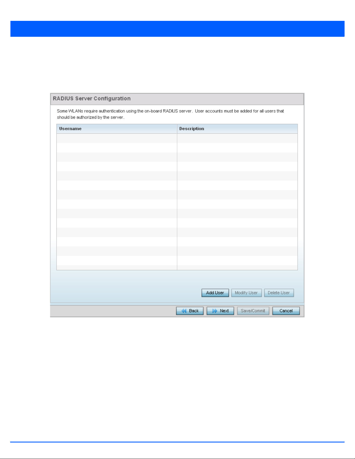
3.1.1.6.1 RADIUS Server Configuration
Wireless LAN Setup
Use the RADIUS Server Configuration screen to configure the users for the onboard RADIUS server. Use the screen to add,
modify and remove RADIUS users.
3 - 17
Figure 3-10 Initial Setup Wizard - RADIUS Server Configuration screen for Typical Setup Wizard
Use the Add User button to add a new RADIUS user. A dialog displays where details about the user is entered.
Page 54

3 - 18 WiNG 5.7.1 Access Point System Reference Guide
Figure 3-11 Initial Setup Wizard - RADIUS Server Configuration - Add User screen for Typical Setup Wizard
1. Use the Add User dialog to provide user information to add to the RADIUS server user database.
• Username – Provide a user name to authenticate the user
• Password – Provide a password to authenticate the user
• Confirm Password – Confirm the password by entering the same password entered in the Password field
• Description – Provide a description for the user created in the RADIUS server user database
2. To create the user and continue with creating another user, select Create. To create the user and close this dialog, click
Create & Close. To close the dialog and abandon the operation, select Cancel.
Use the Modify User button to modify the details for an existing user in the RADIUS user database. Select the user to
modify details for and then click Modify User. The username for the user cannot be modified using this dialog.
Use the Delete User button to remove the details of an existing user from the RADIUS user database. Select the user to
remove and then click Delete User. A confirmation dialog appears. Once confirmed, the user is removed from the RADIUS
user database.
3. Click Next The Typical Setup Wizard displays the Summary and Commit screen. For more information, see Summary And
Commit Screen on page 3-19.
Page 55

3.1.1.7 Summary And Commit Screen
Typ i cal Setu p Wizard
The Summary And Commit screen displays a complete overview of the configurations made in the previous screens.
There is no user intervention or additional settings required. The Summary and Commit screen is an additional means of
validating the configuration before it is deployed.
3 - 19
Figure 3-12 Initial Setup Wizard - Summary And Commit Screen of the Typical Setup Wizard
If the configuration displays as intended, select the Save/Commit button to implement these settings to the access point’s
configuration. If additional changes are warranted based on the summary, either select the target page from the Navigation
Panel, or use the Back button.
Page 56

3 - 20 WiNG 5.7.1 Access Point System Reference Guide
3.1.1.8 Adopt to a controller
Using the Initial Setup Wizard
Adopted to Controller is the default behavior of the access point. When the access point is switched on for the first time, it
looks for a wireless controller on the default subnet and that runs the same WiNG firmware version and automatically adopts
to it. Use the Initial Setup Wizard to configure the preferred wireless controller that the access point must adopt to.
When Adopted to Controller is selected, further configuration settings are displayed in the same screen. Select the Automatic
controller discovery option to enable the access point to be discovered and adopted using layer 2 settings.
If preferring layer 3 adoption, select the Static Controller Configuration option, and define the addresses of the preferred
controllers. When using the static method, you will also need to define whether the access point receives an IP address using
DHCP or if IP resources are provided statically. Up to two (2) controllers can be defined. The access point will try to adopt to
the controller defined in the Controller 1 field first. Should the controller not be found, then the access point tries to adopt to
the controller defined in Controller 2 field.
When preferring layer 3 adoption, configure how an IP will be assigned to this access point. Select Use DHCP to use DHCP to
assign an IP address to this access point. If this access point requires a static IP to be assigned, select Static IP Address/
Subnet and provide the appropriate IP address and net mask. For your convenience, the netmask is automatically set to 24.
Also assign the Default Gateway to forward traffic to.
Figure 3-13 Initial Setup Wizard - Adoption Settings
Select the Save/Commit button to save the current configuration. Select the Cancel button to exit the Initial Setup Wizard
without making any changes. Select the Back button to go back to the previous screen of the Initial Setup Wizard.
Page 57

3.1.2 Advanced Setup Wizard
Using the Initial Setup Wizard
The Advanced Setup is the recommended wizard for users who want more control on how the access point is configured
beyond minimum default settings. This wizard provides additional radio and system information settings.
The Advanced Setup wizard consists of the following:
• Network Topology Selection
• LAN Configuration
• WAN Configuration
• Radio Configuration
• Wireless LAN Setup
• System Information
• Summary And Commit Screen
To configure the access point using the Advanced Setup Wizard:
1. Select Advanced Setup from the Choose One type to Setup the Access Point field.
3 - 21
2. Select Next.
The Advanced Setup Wizard displays the Access Point Settings screen to define the access point's Standalone versus
Virtual Controller AP versus functionality. This screen also enables selection of the country of operation.
Page 58

3 - 22 WiNG 5.7.1 Access Point System Reference Guide
Figure 3-14 Initial Setup Wizard - Access Point Settings screen for Advanced Setup Wizard
3. Select an Access Point Type from the following options:
• Virtual Controller AP - When more than one access point is deployed, a single access point can function as a Virtual
Controller AP. Up to 24 access points can be connected to, and managed by, a single Virtual Controller AP. These
connected access points must be the same model as the Virtual Controller AP. For more information, see
Virtual Controller AP Mode on page 3-8.
• Standalone AP - Select this option to deploy this access point as an autonomous fat access point. A standalone AP is
not managed by a Virtual Controller AP, or adopted by a RFS series wireless controller. For more information see
Standalone Mode on page 3-9.
NOTE: If designating the access point as a Standalone AP, it is recommended that the
access point’s UI be used exclusively to define its device configuration, and not the CLI.
The CLI provides the ability to define more than one profile and the UI does not.
Consequently, the two interfaces cannot be used collectively to manage profiles without
an administrator encountering problems.
Page 59

3 - 23
• Adopted to Controller - Select this option when deploying the access point as a controller managed (Dependent mode)
access point. Selecting this option closes the Initial AP Setup Wizard. An adopted access point obtains its configuration
from a profile stored on its managing controller. Any manual configuration changes are overwritten by the controller upon
reboot. For more information on configuring the access point in the Adopted to Controller mode, see
Adopt to a controller on page 3-35.
4. Select the Next button to start configuring the access point in the selected mode. If the Access Point Type is Virtual
Controller AP or Standard AP, see Network Topology Selection on page 3-24.
If the Access Point Type is Adopted to Controller, see Adopt to a controller on page 3-35.
Page 60

3 - 24 WiNG 5.7.1 Access Point System Reference Guide
3.1.2.1 Network Topology Selection
Advanced Setup Wizard
Use the Network Topology screen to define how the access point manages network traffic. The available modes are:
Figure 3-15 Initial Setup Wizard - Access Point Mode screen for Advanced Setup Wizard
• Router Mode - In Router Mode, the access point routes traffic between the local network (LAN) and the Internet or
external network (WAN). Router mode is recommended in a deployment supported by just a single access point.
• Bridge Mode - In Bridge Mode, the access point depends on an external router for routing LAN and WAN traffic.
Routing is generally used on one device, whereas bridging is typically used in a larger density network. Select Bridge
Mode when deploying this access point with numerous peer access points supporting clients on both the 2.4 GHz and
5.0 GHz radio bands.
NOTE: When Bridge Mode is selected, WAN configuration cannot be performed and the
Initial Setup Wizard does not display the WAN configuration screen.
1. Select Next. The Advanced Setup Wizard displays the LAN Configuration screen to set the access point's LAN interface.
For more information, see LAN Configuration on page 3-25.
Page 61

3.1.2.2 LAN Configuration
Advanced Setup Wizard
Use the LAN Configuration screen to configure the parameters required for setting a Local Area Network (LAN) on the access
point.
3 - 25
Figure 3-16 Initial Setup Wizard - LAN Configuration screen for Advanced Setup Wizard
1. Set the following DHCP and Static IP Address/Subnet information for the LAN interface:
• Use DHCP - Select this option to enable an automatic network address configuration using DHCP server.
• Static IP Address/Subnet - Enter an IP Address and a subnet for the access point's LAN interface. If Use DHCP is
selected, this field is not available. When selecting this option, define the following DHCP Server and Domain Name
Server (DNS) resources, as those fields will become enabled on the bottom portion of the screen.
• Default Gateway - Define a default gateway address for use with the static IP address configuration. This is a required parameter.
• Use on-board DHCP server to assign IP addresses to wireless clients - Select the check box to enable the
access point’s DHCP server to provide IP and DNS information to clients on the LAN interface.
• Range - Enter a starting and ending IP Address range for client assignments on the access point's LAN interface.
Avoid assigning IP addresses from x.x.x.1 - x.x.x.10 and x.x.x.255, as they are often reserved for standard network
services. This is a required parameter.
Page 62

3 - 26 WiNG 5.7.1 Access Point System Reference Guide
• Default Gateway - Define a default gateway address for use with the DHCP server configuration. This is a required
parameter.
• DNS Forwarding - Select this option to allow a DNS server to translate domain names into IP addresses. If this
option is not selected, a primary and secondary DNS resource must be specified. DNS forwarding is useful when a
request for a domain name is made but the DNS server, responsible for converting the name into its corresponding
IP address, cannot locate the matching IP address.
• Primary DNS - Enter an IP Address for the main Domain Name Server providing DNS services for the access point's
LAN interface.
• Secondary DNS - Enter an IP Address for the backup Domain Name Server providing DNS services for the access
point's LAN interface
2. Select Next. The Advanced Setup Wizard displays the Radio Configuration screen to set the access point's radios. For more
information, see Radio Configuration on page 3-29.
If Router Mode is selected as the Network Topology, then the Advanced Setup Wizard displays the WAN configuration
screen. For more information, see WAN Configuration on page 3-13.
Page 63

3.1.2.3 WAN Configuration
Advanced Setup Wizard
NOTE: This option is only available when Router Mode is selected in the Network
Topol og y screen of the Advanced Setup Wizard.
The Advanced Setup Wizard displays the WAN Setting screen to define DHCP and network address information for the WAN
interface. The WAN interface is used to connect the access point to a wired local area network or backhaul.
3 - 27
Figure 3-17 Initial Setup Wizard - WAN Configuration screen of the Advanced Setup Wizard
1. Set the following WAN parameters:
• Use DHCP - Select the radio control to enable an automatic network address configuration using external DHCP servers.
An automatic IP address is configured to the access point’s WAN port using DHCP servers located on the WAN side of
the network.
• Static IP Address/Subnet - Enter an IP Address and a subnet for the access point's WAN interface. If Use DHCP is
selected, this field is not available. When selecting this option, define the following Default Gateway information as
the field will become enabled on the bottom portion of the screen. The IP address defined in this field is assigned to the
WAN interface. The Default Gateway is a router that serves as a access to other networks.
Page 64

3 - 28 WiNG 5.7.1 Access Point System Reference Guide
• Select the port that’s connected to the WAN – Select the port that is connected to the WAN.
• Enable NAT on the WAN Interface – Select this option to enable Network Address Translation on the selected GE
interface.
2. Select Next. The Advanced Setup Wizard displays the Radio Configuration screen to set the access point's radios. For
more information, see Radio Configuration on page 3-29.
Page 65

3.1.2.4 Radio Configuration
Advanced Setup Wizard
Use the Radio Configuration screen to define radio support for the 2.4 GHz radio band, 5.0 GHz radio band or set the radio
as a dedicated sensor.
NOTE: The Radio Configuration screen displays separate configurable fields for each
access point radio. Supported access point models can have from one to three (AP7131)
radios. The ADSP Sensor Server field displays at the bottom of the screen only if one
of the radios has been dedicated as a sensor.
3 - 29
Figure 3-18 Initial Setup Wizard - Radio Configuration screen of the Advanced Setup Wizard
1. Set the following for each radio:
• Configure as a Data Radio - Select this option to dedicate this radio to WLAN client support in the selected 2.4 GHz
or 5.0 GHz radio band.
• Radio Frequency Band - Select the 2.4 GHz or 5.0 GHz radio band to use with the radio when selected as a Data Radio.
The selected band is used for WLAN client support. Consider selecting one radio for 2.4 GHz and another for
5.0 GHz support (if using a dual or three radio model) when supporting clients in the 802.11bg, 802.11n and 802.11ac
bands.
Page 66

3 - 30 WiNG 5.7.1 Access Point System Reference Guide
• Power Level - Use the spinner control to select a 1 - 23 dBm minimum power level to assign to this radio in selected
2.4 GHz or 5.0 GHz band. 1 dBm is the default setting.
• Channel Mode - Select either Random, Best or Static. Select Random for use with a 802.11a/n radio. To comply with
Dynamic Frequency Selection (DFS) requirements in the European Union, the 802.11a/n radio uses a randomly selected
channel each time the access point is powered on. Select Best to enable the access point to scan non-overlapping
channels and listen for beacons from other access points. After the channels are scanned, it will select the channel with
the fewest access points. In the case of multiple access points on the same channel, it will select the channel with the
lowest average power level. When Constantly Monitor is selected, the access point will continuously scan the network
for excessive noise and sources of interference. Select Static to assign the access point a permanent channel and scan
for noise and interference only when initialized.
• Configure as a Sensor Radio - Select this option to dedicate the radio to sensor support exclusively. When functioning
as a sensor, the radio scans in sensor mode across all channels within the 2.4 and 5.0 GHz bands to identify potential
threats. If dedicating a radio as a sensor resource, a primary and secondary ADSP server must be specified as an ADSP
management resource.
NOTE: If configuring an AP6511 or AP6521 model access point as a sensor, the access
point will require a reboot before its sensor functionality is invoked. The reboot can take
place at the completion of the Initial Setup Wizard.
• Disable the Radio - Select this option to disable this radio, thus prohibiting it from either providing WLAN or sensor
support. Verify this course action with your network administrator before rendering the radio offline.
2. Select Next. The Advanced Setup Wizard displays the Wireless LAN Setup screen to set the access point's Wireless LAN
interface configuration. For more information, see Wireless LAN Setup on page 3-31.
Page 67

3.1.2.5 Wireless LAN Setup
Advanced Setup Wizard
A Wireless Local Area Network (WLAN) is a data-communications system and wireless local area network that flexibly extends
the functionality of a wired LAN. A WLAN links two or more computers or devices using spread-spectrum or OFDM modulation
based technology. WLANs do not require lining up devices for line-of-sight transmission, and are thus, desirable for wireless
networking. Roaming users can be handed off from one access point to another, like a cellular phone system. WLANs can
therefore be configured around the needs of specific user groups, even when they are not in physical proximity.
Use the Wireless LAN Setup screen to configure the WLAN parameters. Up to two (2) WLANs can be configured for the access
point.
3 - 31
Figure 3-19 Initial Setup Wizard - WAN Configuration screen for Advanced Setup Wizard
1. Set the following WLAN1 Configuration parameters:
• SSID – Configure the SSID for the WLAN.
• WLAN Type – Configure the encryption and authentication to use with this WLAN.
• No Authentication and No Encryption – Configures a network without any authentication. This means any device
can access the network. This option also configures the network without encryption. This means any data transmitted
through the network is in plain text.
• Captive Portal Authentication and No Encryption – Configures a network using a RADIUS server to authenticate
Page 68

3 - 32 WiNG 5.7.1 Access Point System Reference Guide
users before allowing them on to the network. Once on the network, no encryption is used for the data transmitted
through the network. Select this option to use a Web page (either internally or externally hosted) to authenticate users
before access is granted to the network.
• External RADIUS Server – When selected, provide the IP address of the external RADIUS server used for user authentication. Also enter the shared secret in the RADIUS Shared Secret field.
• Onboard RADIUS Server – When selected, a new screen displays where further configuration can be performed.
For more information, see RADIUS Server Configuration on page 3-17.
• PSK authentication, WPA2 encryption – Configures a network that uses PSK authentication and WPA2 encryption.
Select this option to implement a pre-shared key that must be correctly shared between the access point and requesting
clients on the WLAN.
• WPA Key – Provide a 64 character HEX key or 8-63 character ASCII key. Use the drop-down to specify the type of
key provided. Select ASCII or HEX to specify the key type provided in the WPA Key field.
• EAP Authentication and WPA2 Encryption – Configures a network that uses EAP authentication and WPA2
encryption.Select this option to authenticate clients within this WLAN through the exchange and verification of
certificates.
• External RADIUS Server – When selected, provide the IP address of the external RADIUS server used for user authentication. Also provide the shared secret in the RADIUS Shared Secret field.
• Onboard RADIUS Server – When selected, a new screen is displayed where further configuration can be performed. For more information, see RADIUS Server Configuration on page 3-17.
2. Select Next. The Advanced Setup Wizard displays the RADIUS Server Configuration screen if required. This screen is only
displayed when Onboard RADIUS Server is selected for either Captive Portal Authentication And No Encryption or
for EAP Authentication and WPA2 Encryption fields. For more information, see RADIUS Server Configuration on page
3-17.
Otherwise, the Advanced Setup Wizard displays the System Information screen. For more information, see System
Information on page 3-33.
Page 69

3.1.2.6 System Information
Advanced Setup Wizard
Use the System Information screen to define the device’s location, contact information for an administrator, and the country
where this access point is deployed.
3 - 33
Figure 3-20 Initial Setup Wizard - System Information screen for the Advanced Setup Wizard
• Location - Provide the location of the access point.
• Contact - Specify the contact information for the administrator. The credentials provided should accurately reflect the
individual responding to service queries.
• Country - Select the country where the access point is deployed. The access point prompts for the correct country code
on the first login. A warning message also displays stating an incorrect country setting may result in illegal radio
operation. Selecting the correct country is central to legal operation. Each country has its own regulatory restrictions
concerning electromagnetic emissions and the maximum RF signal strength that can be transmitted. This is a required
parameter.
• Time Zone - Set the time zone where the access point is deployed. This is a required parameter. The setting should be
complimentary with the selected deployment country.
1. Select Next. The Advanced Setup Wizard displays the Summary and Commit screen to summarize the screens (pages) and
settings updated using the Initial AP Setup Wizard. For more information, see Summary And Commit Screen on page 3-34.
Page 70

3 - 34 WiNG 5.7.1 Access Point System Reference Guide
3.1.2.7 Summary And Commit Screen
Advanced Setup Wizard
The Summary And Commit screen displays an overview of the updates made using the Advanced Setup Wizard.
There is no user intervention or additional settings required. This screen is an additional means of validating the configuration
before it is deployed. However, if a screen displays settings not intended as part of the initial configuration, the screen can be
selected from within the Navigation Panel and its settings modified accordingly.
Figure 3-21 Initial Setup Wizard - Summary and Commit screen for the Advanced Setup Wizard
If the configuration displays as intended, select Save/Commit to implement these settings to the access point. If additional
changes are warranted, either select the target page from the Navigational Panel, or use the Back button.
Page 71
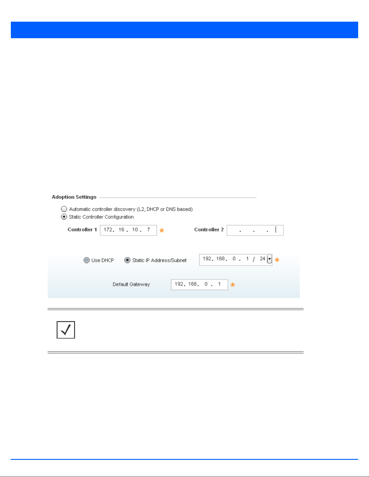
3.1.2.8 Adopt to a controller
Advanced Setup Wizard
When the access point is powered on for the first time, it looks for a wireless controller on the default subnet running the same
firmware version and automatically adopts to it.
When Adopted to Controller is selected, further configuration settings are displayed in the same screen. Select Automatic
controller discovery to enable the access point to be discovered and adopted using layer 2 settings.
If preferring layer 3 adoption, select Static Controller Configuration, and define the addresses of the preferred controllers.
When using the static method, define whether the access point receives an IP address using DHCP or if IP resources are
provided statically. Up to two (2) controllers can be defined. The access point will try to adopt to the controller defined in the
Controller 1 field first. Should the controller not be found, the access point tries to adopt to the controller defined in
Controller 2 field.
When preferring layer 3 adoption, configure how an IP is assigned to this access point. Select Use DHCP to use DHCP to assign
an IP address to this access point. If this access point requires a static IP, select Static IP Address/Subnet and provide the
appropriate IP address and net mask. For your convenience, the netmask is automatically set to 24. Also assign the Default
Gateway for forwarding traffic.
3 - 35
Figure 3-22 Initial Setup Wizard - Adoption Settings
NOTE: The best way to administer a network populated by numerous access points is to
configure them directly from their managing controller or Virtual Controller AP. If an
access point’s configuration requires an exception from the wireless controller or Virtual
Controller AP’s assigned profile configuration, the administrator should apply a Device
Override to change just that access point’s configuration.
1. Select the Save/Commit button to save the current configuration. Select the Cancel button to exit the Initial Setup Wizard
without making any changes. Select the Back button to go back to the previous screen of the Initial Setup Wizard.
Page 72

3 - 36 WiNG 5.7.1 Access Point System Reference Guide
Page 73

CHAPTER 4
DASHBOARD
The dashboard allows network administrators to review and troubleshoot the operation of the devices comprising the access
point managed network. Use the dashboard to review the current network topology, assess the network’s component health
and diagnose problematic device behavior.
By default, the Dashboard screen displays the System Dashboard, which is the top level in the device hierarchy.
The dashboard provides the following tools and diagnostics:
• Dashboard
• Network View
Page 74

4 - 2 WiNG 5.7.1 Access Point System Reference Guide
4.1 Dashboard
Dashboard
The Dashboard screen displays device information organized by device association and inter-connectivity between an access
point and connected wireless clients.
To review dashboard information:
1. Select Dashboard. Expand the System menu item on the upper, left-hand, side of the UI and select either an access point
or connected client.
The Dashboard screen displays the Health tab by default.
4.1.1 Dashboard Conventions
The Dashboard screen displays device information using the following conventions:
• Health – Displays the state of the access point managed network.
• Inventory – Displays the physical devices managed by the access point.
Figure 4-1 Dashboard - Health tab
Page 75

4.1.1.1 Health
Dashboard Conventions
The Health tab displays performance and utilization data for the access point managed network.
4 - 3
For more information see:
• Device Details
• Radio RF Quality Index
• Radio Utilization Index
• Client RF Quality Index
4.1.1.1.1 Device Details
Health
The Device Details field displays model and version information.
Figure 4-2 Dashboard - Health tab
Page 76

4 - 4 WiNG 5.7.1 Access Point System Reference Guide
Figure 4-3 Dashboard - Health tab - Device Details field
The Device Details field displays the name assigned to the selected access point, factory encoded MAC address, primary IP
address, model type, RF Domain, software version, uptime, CPU and RAM information and system clock. Use this data to
determine whether a software upgrade is warranted, or if the system clock needs adjustment.
Periodically select Refresh (at the bottom of the screen) to update the data displayed.
4.1.1.1.2 Radio RF Quality Index
Dashboard Conventions
The Radio RF Quality Index displays a RF quality table for the access point’s single default RF Domain. It is a percentage of
the overall effectiveness of the RF environment. It is a function of the data rate in both directions, the retry rate and the error
rate.
RF Quality displays as the average quality index for the single RF Domain utilized by the access point. The table lists the bottom
five (5) RF quality values for the RF Domain.
The quality is measured as:
• 0-20 – Very poor quality
• 20-40 – Poor quality
Figure 4-4 Dashboard - Health tab - Radio RF Quality Index field
• 40-60 – Average quality
• 60-100 – Good quality
The access point’s RF Domain allows an administrator to assign configuration data to multiple devices deployed in a common
coverage area, such as in a floor, building or site. The RF Domain contains policies that can determine a Smart RF or WIPS
configuration.
Use this diagnostic information to define measures to improve radio performance in respect to wireless client load and radio
band.
Page 77

Periodically select Refresh (at the bottom of the screen) to update the RF quality data.
4.1.1.1.3 Radio Utilization Index
Dashboard Conventions
The Radio Utilization Index displays how efficiently the RF medium is used by the access point. Traffic utilization is defined
as the percentage of throughput relative to the maximum possible throughput.
Refer to the number or errors and dropped packets to assess radio performance relative to the number of packets both
transmitted and received.
Periodically select Refresh (at the bottom of the screen) to update the radio utilization information displayed.
4 - 5
4.1.1.1.4 Client RF Quality Index
Dashboard Conventions
The Client RF Quality Index displays a list of the worst 5 performing clients managed by the selected access point.
Figure 4-5 Dashboard - Health tab - Radio Utilization Index field
Figure 4-6 Dashboard - Health tab - Client RF Quality Index field
Page 78

4 - 6 WiNG 5.7.1 Access Point System Reference Guide
1. The Client RF Quality Index displays the following:
Worst 5 Lists the worst 5 performing client radios connected to the access point. The RF Quality
Index measures the overall effectiveness of the RF environment as a percentage. It is a
function of the connect rate in both directions, as well as the retry rate and the error rate.
The quality is measured as:
• 0-20 – Very poor quality
• 20-40 – Poor quality
• 40-60 – Average quality
• 60-100 – Good quality
Client MAC Displays the factory encoded MAC address assigned to each connected radio listed. Use
this information to assist in the identification of poorly performing radios.
Retry Rate
2. Periodically select Refresh (at the bottom of the screen) to update client RF quality.
Lists the number of retries attempted to re-connect with the listed radio.
Page 79

4.1.1.2 Inventory
Dashboard Conventions
The Inventory tab displays information relative to the devices managed by the selected access point. The Inventory screen
affords a system administrator an overview of the number and state of managed devices. The screen contains links to display
more granular data specific to a radio.
4 - 7
Figure 4-7 Dashboard - Inventory tab
The Inventory tab is partitioned into the following fields:
• Radio Types
• WLAN Utilization
• Wireless Clients
• Clients by Radio Type
Page 80

4 - 8 WiNG 5.7.1 Access Point System Reference Guide
4.1.1.2.1 Radio Types
Inventory
The Radio Types field displays the total number and types of radios managed by the selected access point.
Figure 4-8 Dashboard - Inventory tab - Radio Types field
Refer to the Total Radios column to review the number of managed radios. Additionally, use the bar graphs to assess the
number WLANs utilized by supported radio bands.
Periodically select Refresh (at the bottom of the screen) to update the radio information.
4.1.1.2.2 WLAN Utilization
Inventory
The WLAN Utilization field displays the top 5 WLANs utilized by this access point in respect to client support. The utilization
index measures how efficiently the RF medium is utilized. It is defined as a percentage of the current throughput relative to the
maximum throughput possible.
The quality is measured as:
• 0-20 – Very low utilization
• 20-40 – Low utilization
• 40-60 – Moderate utilization
• 60 and above – High utilization
Figure 4-9 Dashboard - Inventory tab - WLAN Utilization field
Periodically select Refresh (at the bottom of the screen) to update WLAN utilization information.
4.1.1.2.3 Wireless Clients
Inventory
The Wireless Clients field displays information about the wireless clients managed by the selected access point.
Page 81

4 - 9
Figure 4-10 Dashboard - Inventory tab - Wireless Clients field
Information within the Wireless Clients field is presented in two tables. The first table lists the total number of wireless
clients managed by this access point. The second table lists an ordered ranking of radios based on their supported client count.
Use this information to assess if an access point managed radio is optimally deployed in respect to its radio type and intended
client support requirements.
NOTE: AP6522, AP6522, AP6532, AP6562, AP8132, AP8232, AP7131, AP7161 and
AP7181 model access points can support up to 256 client connections to a single access
point. AP6511 and AP6521 model access points (both single radio models) can support
up to 128 client connections per access point.AP6522, AP6522M, AP6532, AP6562,
AP71XX, AP75XX, AP81XX and AP82XX can support up to 256 client connections per
access point. AP6511 and AP6521 model access points (both single radio models) can
support up to 128 client connections per access point.
4.1.1.2.4 Clients by Radio Type
Inventory
The Clients by Radio Type field displays a bar graph illustrating the number of connected clients currently operating on
supported radio bands.
For 5.0 GHz, clients are displayed supporting the 802.11a and 802.11an radio bands. For 2.4 GHz, clients are displayed
supporting the 802.11b, 802.11bg, and 802.11bgn radio bands. Use this information to determine if all the access point’s client
radio bands are optimally supported for the access point’s radio coverage area.
Figure 4-11 Dashboard - Inventory tab - Clients by Radio Type field
Page 82

4 - 10 WiNG 5.7.1 Access Point System Reference Guide
4.2 Network View
Dashboard
The Network View displays device topology association between a selected access point, its RF Domain and its connected
clients.
Access points and clients can be selected and viewed using various color schemes in respect to neighboring access points,
connected devices and performance criteria. Display options can be utilized to review device performance and utilization, as
well as the RF band, channel and vendor. For more information, see Network View Display Options on page 4-11.
To review a device’s Network Topology, select Dashboard > Network View.
Figure 4-12 Network View Topology
The left-hand side of the Network View screen contains an expandable System Browser where access points can be selected
and expanded to display connected clients. Navigate the System Browser to review device connections within the access point
managed network. Many of these peer access points are available for connection to access points in Virtual Controller AP
mode.
Page 83
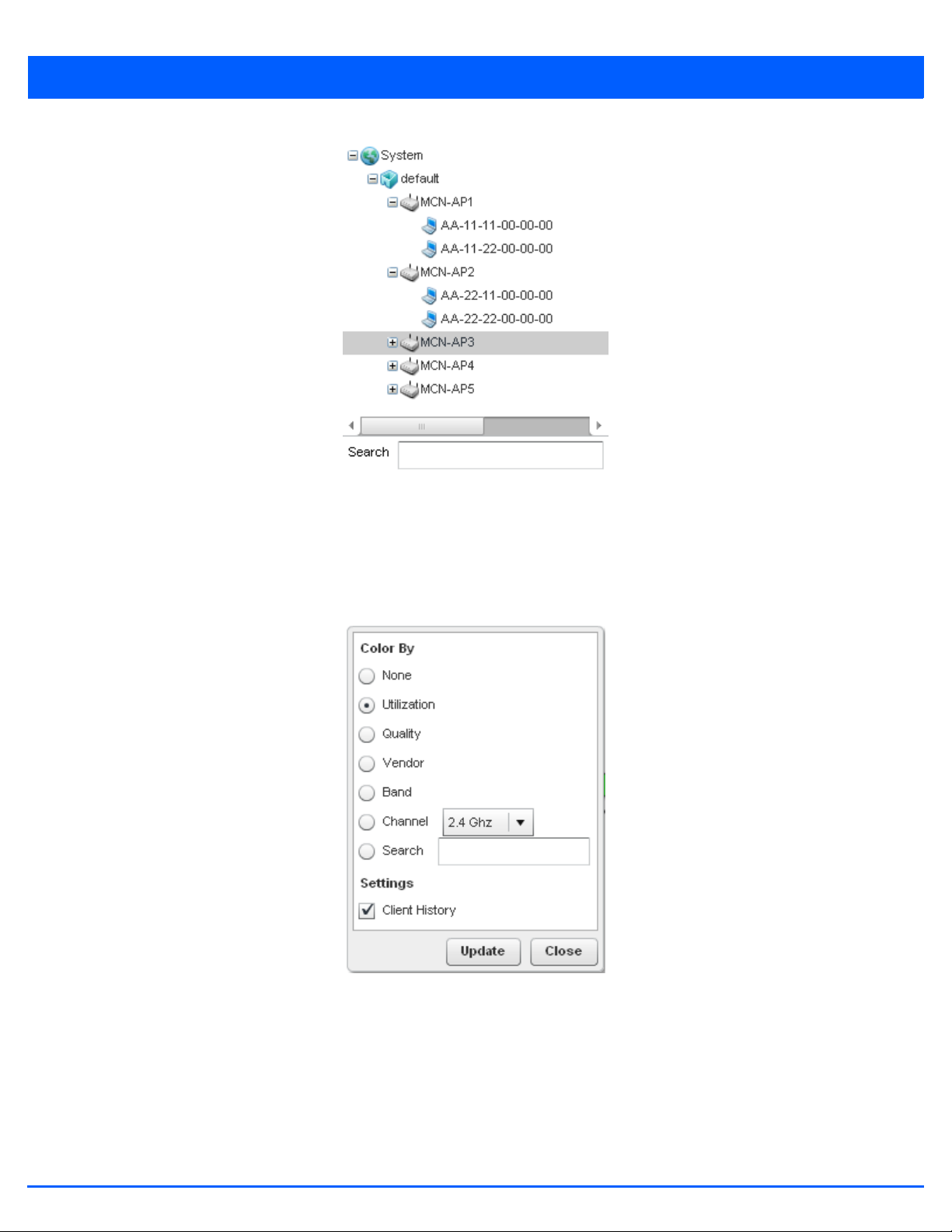
Figure 4-13 Network View - System Browser
4 - 11
4.2.1 Network View Display Options
Network View
1. Select the blue Options link right under the Network View banner to display a menu for different device interaction display
options.
Figure 4-14 Network View - Display Options
2. The following display filter options are available:
• None - Select this option to keep the Network View display as it currently appears, without any additional color or device
interaction adjustments.
• Utilization – Select this option to filter based on the percentage of current throughput relative to maximum throughput.
Utilization results include: Red (Bad Utilization), Orange (Poor Utilization), Yellow (Fair Utilization) and Green (Good
Utilization).
• Quality – Select this option to filter based on the overall RF health. RF health is a ratio of connection rate, retry rates,
Page 84

4 - 12 WiNG 5.7.1 Access Point System Reference Guide
and error rates. Quality results include: Red (Bad Quality), Orange (Poor Quality), Yellow (Fair Quality) and Green (Good
Quality).
• Vendor – Displays the device manufacturer.
• Band – Select this option to filter based on the 2.4 or 5.0 GHz radio band of connected clients. Results include: Yellow
(2.4 GHz radio band) and Blue (5.0 GHz radio band). Selecting Band is a good way to determine whether 2.4 and 5.0 GHz
radios are optimally deployed in respect to the access point client loads on both bands.
• Channel - Use the drop-down menu to filter whether device connections should be displayed in either the 2.4 or 5.0 GHz
band.
• Search - Enter search criteria in the provided text field and select the Update button to isolate located variables in blue
within the Network View display.
3. Select the Update button to update the display with the changes made to the filter options. Select Close to close the
options field and remove it from the Network View.
4.2.2 Device Specific Information
Network View
A device specific information screen is available for individual devices selected from within the Network View (not the System
Browser). The screen displays the name assigned to the device, its model, factory encoded MAC address, number of radios
within the device, number of connected clients, as well as the highest and lowest reported quality, utilization and Signal to
Noise Ratio (SNR). This information cannot be modified by the administrator.
Figure 4-15 Network View - Device Specific Information
Optionally select the Statistics link at the bottom of the display to open a screen where access point device data can be
reviewed on a much more granular level. For more information, see Health on page 4-3.
Page 85

CHAPTER 5
DEVICE CONFIGURATION
Access points can either be assigned unique configurations to support a particular deployment objective or have an existing RF
Domain or profile configuration modified (overridden) to support a requirement that deviates its configuration from the
configuration shared by its peer access points.
Refer to the following to set an access point’s sensor functionality, Virtual Controller AP designation, and license and certificate
usage configuration:
• RF Domain Configuration
• System Profile Configuration
• Managing Virtual Controllers
• Overriding a Device Configuration
• Managing an Event Policy
An RF Domain allows an administrator to assign comparable configuration data to multiple access points deployed in a common
coverage area (floor, building or site). In such instances, there are many configuration attributes these devices share, as their
general client support roles are quite similar. However, access point configurations may need periodic refinement and overrides
from their original RF Domain administered design. For more information, see RF Domain Overrides on page 5-213.
Profiles enable administrators to assign a common set of configuration parameters and policies to access points of the same
model. Profiles can be used to assign shared network, wireless and security parameters to access points across a large, multi
segment, site. The configuration parameters within a profile are based on the hardware model the profile was created to
support. To define a configuration profile for a specific access point model, refer to System Profile Configuration on page 5-14.
However, device Profile configurations may need periodic refinement from their original administered design. Consequently, a
device profile could be applied an override from a configuration shared amongst numerous peer devices deployed within a
particular site. For more information, see Device Overrides on page 5-216.
Page 86

5 - 2 WiNG 5.7.1 Access Point System Reference Guide
5.1 RF Domain Configuration
Device Configuration
An access point’s configuration consists of numerous elements including a RF Domain, WLAN and device specific settings. RF
Domains are used to assign regulatory, location and relevant policies to access points of the same model. For example, an
AP6532 RF Domain can only be applied to another AP6532 model.
An access point RF Domain allows an administrator to assign configuration data to multiple access points deployed in a
common coverage area (floor, building or site). In such instances, there are many configuration attributes these access points
share, as their general client support roles are quite similar.
However, an access point’s RF Domain configuration may need periodic refinement from its original RF Domain designation.
Unlike a RFS series wireless controller, an access point supports just a single RF domain. Thus, administrators should be aware
that overriding an access point’s RF Domain configuration results in a separate configuration that must be managed in addition
to the RF Domain configuration. Thus, a configuration should only be overridden when needed. For more information, see RF
Domain Overrides on page 5-213.
The access point’s RF Domain can have a WIPS sensor configuration applied. For more information on defining a WIPS sensor
configuration for use with the access point’s RF Domain, see RF Domain Sensor Configuration on page 5-3.
To set a RF Domain configuration:
1. Select the Configuration tab from the Web UI.
2. Select Devices.
3. Select RF Domains from the options on left-hand side of the UI.
The RF Domain Basic Configuration tab displays by default with the access point RF Domain activated.
Figure 5-1 RF Domain - Basic Configuration tab
Page 87

4. Define the following Basic Configuration values for the access point RF Domain:
Location Assign the physical location of the RF Domain. This name could be as specific as the floor
of a building, or as generic as an entire site. The location defines the physical area where
a common set of access point configurations are deployed and managed by the RF Domain
policy.
Contact Provide the name of the contact E-mail (or administrator) assigned to respond to events
created by or impacting the RF Domain.
Time Zone Set the geographic time zone for the RF Domain. The RF Domain can contain unique
country codes and time zone information to access points deployed across different states
or countries, thus making them ideal for managing device configurations across different
geographical deployments.
Country Define the two-digit country code set for the RF Domain. The country code must be set
accurately to avoid the policy’s illegal operation, as device radios transmit in specific
channels unique to the country of operation.
Controller Managed Select this option to indicate this RF Domain is managed by adopting controllers or service
platforms. This option is disabled by default.
5 - 3
5. Refer to the Smart Scan field to define the channels for smart scan.
Enable Dynamic Channel Select this option to enable dynamic channel scan.
2.4 GHz Channels Use the Select drop-down menu to select channels to scan in the 2.4 GHz band. Selected
channels are highlighted with a grey background. Unselected channels are highlighted
with a white background. Multiple channels can be selected at the same time.
5.0 GHz Channels Use the Select drop-down menu to select channels to scan in the 5.0 GHz band. Selected
channels are highlighted with a grey background. Unselected channels are highlighted
with a white background. Multiple channels can be selected at the same time.
6. Refer to the Statistics field to define how RF Domain statistics are updated.
Update Interval Set a statistics update interval of 0 or 5-3600 seconds for updates retrieved from the
access point.
7. Use the Initial Setup Wizard to configure the device. For more information on using the Initial Setup Wizard, see Using
the Initial Setup Wizard on page 3-2.
8. Select OK to save the changes to the Basic Configuration, or select Reset to revert to the last saved configuration.
5.1.1 RF Domain Sensor Configuration
RF Domain Configuration
Wireless Intrusion Protection System (WIPS) protects wireless client and access point radio traffic from attacks and
unauthorized access. WIPS provides tools for standards compliance and around-the-clock wireless network security in a
distributed environment. WIPS allows administrators to identify and accurately locate attacks, rogue devices and network
vulnerabilities in real time and permits both a wired and wireless lockdown of wireless device connections upon
acknowledgement of a threat.
In addition to dedicated AirDefense sensors, an access point radio can function as a sensor and upload information to a
dedicated WIPS server (external to the access point). Unique WIPS server configurations can be used to ensure a WIPS server
configuration is available to support the unique data protection needs of a RF Domain.
Page 88

5 - 4 WiNG 5.7.1 Access Point System Reference Guide
WIPS is not supported on a WLAN basis, rather, sensor functionality is supported on the access point radio(s) available to each
managed WLAN. When an access point radio is functioning as a WIPS sensor, it is able to scan in sensor mode across all legal
channels within the 2.4 and 5.0 GHz band. Sensor functionality is not provided by the access point alone. The access point
works in conjunction with a dedicated WIPS server.
To define a WIPS server configuration used with the access point’s RF Domain:
1. Select the Configuration tab from the Web UI.
2. Select Devices.
3. Select RF Domains from the options on left-hand side of the UI.
4. Select the Sensor Configuration tab.
Figure 5-2 RF Domain - Sensor Configuration tab
5. Either select the + Add Row button to create a new WIPS server configuration or highlight an existing Sensor Server
Configuration and select the Delete icon to remove it.
6. Use the spinner control to assign a numerical Server ID to each WIPS server defined. The server with the lowest defined
ID is the first reached by the access point. The default ID is 1.
7. Provide the numerical (non DNS) IP Address of each server used as a WIPS sensor server by the RF Domain.
8. Use the spinner control to specify the Port of each WIPS server. The default port is 443.
9. Select OK to save the changes to the AirDefense WIPS configuration, or select Reset to revert to the last saved
configuration.
5.1.2 RF Client Name Configuration
The Client Name Configuration screen displays clients connected to RF Domain member access points adopted by
networked controllers or service platforms. Use the screen to associate administrator assigned client names to specific
connected client MAC addresses for improved client management.
To define a client name configuration used with RF Domain member devices:
1. Select the Configuration tab from the Web UI.
2. Select Devices.
Page 89

3. Select RF Domains from the options on left-hand side of the UI.
4. Select the Client Name tab.
5 - 5
Figure 5-3 RF Domain Client Configuration screen
5. Either select the + Add Row button to create a new client configuration or highlight an existing configuration and select
the Delete icon to remove it.
6. Enter the client’s factory coded MAC address.
7. Assign a Name to the RF Domain member access point’s connected client to assist in its easy recognition.
8. Select OK to save the changes to the configuration, or select Reset to revert to the last saved configuration.
5.1.3 RF Domain Alias Configuration
RF Domain Configuration
With large deployments, the configuration of remote sites utilizes a set of shared attributes, of which a small set of attributes
are unique for each location. For such deployments, maintaining separate configuration (WLANs, profiles, policies and ACLs)
for each remote site is complex. Migrating any global change to a particular configuration item to all the remote sites is a
complex and time consuming operation.
Also, this practice does not scale gracefully for quick growing deployments.
An alias enables an administrator to define a configuration item, such as a hostname, as an alias once and use the defined
alias across different configuration items such as multiple ACLs.
Once a configuration item, such as an ACL, is utilized across remote locations, the alias used in the configuration item (ACL) is
modified to meet local deployment requirement. Any other ACL or other configuration items using the modified alias also get
modified, simplifying maintenance at the remote deployment.
Aliases have scope depending on where the alias is defined. Alias are defined with the following scopes:
• Global aliases are defined from the Configuration > Network > Alias screen. Global aliases are available for use globally
across all devices, profiles and RF Domains in the system.
• Profiles aliases are defined from Configuration > Devices > System Profile > Network > Alias screen. These aliases
are available for use to a specific group of wireless controllers or access points. Alias values defined in this profile override
alias values defined within global aliases.
Page 90

5 - 6 WiNG 5.7.1 Access Point System Reference Guide
• RF Domain aliases are defined from Configuration > Devices > RF Domain > Alias screen. These aliases are available
for use for a site as a RF Domain is site specific. RF Domain alias values override alias values defined in a global alias or a
profile alias configuration.
• Device aliases are defined from Configuration > Devices > Device Overrides > Network > Alias screen. Device alias
are utilized by a single device only. Device alias values override alias values defined in a global alias, profiles alias or RF
Domain alias configuration.
Using an alias, configuration changes made at a remote location override any updates at the management center. For example,
if an Network Alias defines a network range as 192.168.10.0/24 for the entire network, and at a remote deployment location,
the local network range is 172.16.10.0/24, the network alias can be overridden at the deployment location to suit the local
requirement. For the remote deployment location, the network alias works with the 172.16.10.0/24 network. Existing ACLs
using this network alias need not be modified and will work with the local network for the deployment location. This simplifies
ACL definition and management while taking care of specific local deployment requirements.
Alias can be classified as:
• Network Basic Alias
• Network Group Alias
• Network Service Alias
Page 91

5.1.3.1 Network Basic Alias
RF Domain Configuration
A basic alias is a set of configurations that consist of VLAN, Host, Network and Address Range alias configurations. VLAN
configuration is a configuration for optimal VLAN re-use and management for local and remote deployments. A host alias
configuration is for a particular host device’s IP address. A network alias configuration is utilized for an IP address on a
particular network. An address range alias is a configuration for a range of IP addresses.
A basic alias configuration can contain multiple instances for each of the five (5) alias types.
To edit or delete a basic alias configuration:
1. Select Configuration tab from the Web user interface.
2. Select Devices.
3. Select RF Domain.
4. Select the Basic Alias tab. The Basic Alias screen displays.
5 - 7
Figure 5-4 RF Domain - Basic Alias screen
5. Select + Add Row to define VLAN Alias settings:
Page 92

5 - 8 WiNG 5.7.1 Access Point System Reference Guide
Use the VLAN Alias field to create unique aliases for VLANs that can be used at different deployments. For example, if a
named VLAN is defined as 10 for the central network, and the VLAN is set at 26 at a remote location, the VLAN can be
overridden at the deployment location with an alias. At the remote deployment location, the network is functional with a
VLAN ID of 26 but utilizes the name defined at the centrally managed network. A new VLAN need not be created specifically
for the remote deployment.
Name If adding a new VLAN Alias, provide it a distinguishing name up to 32 characters. The alias
name always starts with a dollar sign ($).
VLAN Use the spinner control to set a numeric VLAN from 1 - 4094.
A VLAN alias can be used to replace VLANs in the following locations:
• Bridge VLAN
• IP Firewall Rules
• L2TPv3
• Switchport
• Wireless LANs
6. Select + Add Row to define Address Range Alias settings:
Use the Address Range Alias field to create aliases for IP address ranges that can be utilized at different deployments.
For example, if an ACL defines a pool of network addresses as 192.168.10.10 through 192.168.10.100 for an entire network,
and a remote location’s network range is 172.16.13.20 through 172.16.13.110, the remote location’s ACL can be overridden
using an alias. At the remote location, the ACL works with the 172.16.13.20-110 address range. A new ACL need not be
created specifically for the remote deployment location.
Name If adding a new Address Alias, provide it a distinguishing name up to 32 characters. The
alias name always starts with a dollar sign ($).
Start IP Set a starting IP address used with a range of addresses utilized with the address range
alias.
End IP Set a ending IP address used with a range of addresses utilized with the address range
alias.
An address range alias can be used to replace an IP address range in IP firewall rules.
7. Select + Add Row to define Host Alias settings:
Use the Host Alias field to create aliases for hosts that can be utilized at different deployments. For example, if a central
network DNS server is set a static IP address, and a remote location’s local DNS server is defined, this host can be
overridden at the remote location. At the remote location, the network is functional with a local DNS server, but uses the
name set at the central network. A new host need not be created at the remote location. This simplifies creating and
managing hosts and allows an administrator to better manage specific local requirements
Name If adding a new Host Alias, provide it a distinguishing name up to 32 characters. The alias name
always starts with a dollar sign ($).
Host Set the IP address of the host machine.
A host alias can be used to replace hostnames in the following locations:
• IP Firewall Rules
•DHCP
Page 93

8. Select + Add Row to define Network Alias settings:
Use the Network Alias field to create aliases for IP networks that can be utilized at different deployments. For example,
if a central network ACL defines a network as 192.168.10.0/24, and a remote location’s network range is 172.16.10.0/24,
the ACL can be overridden at the remote location to suit their local (but remote) requirement. At the remote location, the
ACL functions with the 172.16.10.0/24 network. A new ACL need not be created specifically for the remote deployment.
This simplifies ACL definition and allows an administrator to better manage specific local requirements.
Name If adding a new Network Alias, provide it a distinguishing name up to 32 characters. The alias
name always starts with a dollar sign ($).
Network Provide a network address in the form of host/mask.
A network alias can be used to replace network declarations in the following locations:
• IP Firewall Rules
•DHCP
9. Select + Add Row to define String Alias settings:
Use the String Alias field to create aliases for strings that can be utilized at different deployments. For example, if the
main domain at a remote location is called loc1.domain.com and at another deployment location it is called
loc2.domain.com, the alias can be overridden at the remote location to suit the local (but remote) requirement. At one
remote location, the alias functions with the loc1.domain.com domain and at the other with the loc2.domain.com domain.
5 - 9
Name If adding a new String Alias, provide it a distinguishing name up to 32 characters. The alias
name always starts with a dollar sign ($).
Value Provide a string value to use in the alias.
A string alias can be used to replace a domain name string in DHCP.
10. Select OK when completed to update the basic alias rules. Select Reset to revert the screen back to its last saved
configuration.
Page 94

5 - 10 WiNG 5.7.1 Access Point System Reference Guide
5.1.3.2 Network Group Alias
RF Domain Configuration
A network group alias is a set of configurations that consist of host and network configurations. Network configurations are
complete networks in the form 192.168.10.0/24 or IP address range in the form 192.168.10.10-192.168.10.20. Host
configuration is in the form of single IP address, 192.168.10.23.
A network group alias can contain multiple definitions for host, network, and IP address range. A maximum of eight (8) host
entries, eight (8) network entries and eight (8) IP addresses range entries can be configured inside a network group alias. A
maximum of 32 network group alias entries can be created.
A network group alias is used in IP firewall rules to substitute hosts, subnets and IP address ranges:
To edit or delete a network alias configuration:
1. Select Configuration tab from the Web user interface.
2. Select Devices.
3. Select RF Domain.
4. Select the Network Group Alias tab.
Figure 5-5 RF Domain - Network Group Alias screen
Name Displays the administrator assigned name of the network group alias.
Host Displays all host aliases configured in this network group alias. Displays a blank column if no
host alias is defined.
Network Displays all network aliases configured in this network group alias. Displays a blank column if
no network alias is defined.
Page 95

5. Select Edit to modify the attributes of an existing policy or Delete to remove obsolete policies from the list of those
available. Select Add to create a new Network Group Alias. Copy to copy an existing policy or Rename to rename an
existing policy.
5 - 11
Figure 5-6 RF Domain - Network Group Alias Add screen
6. If adding a new Network Group Alias, provide it a name of up to 32 characters.
NOTE: The Network Group Alias Name always starts with a dollar sign ($).
7. Define the following network group alias parameters:
Host Specify the Host IP address for up to eight IP addresses supporting network aliasing. Select the
down arrow to add the IP address to the table.
Network Specify the netmask for up to eight IP addresses supporting network aliasing. Subnets can
improve network security and performance by organizing hosts into logical groups. Applying the
subnet mask to an IP address separates the address into a host address and an extended
network address. Select the down arrow to add the mask to the table.
8. Within the Range table, use the + Add Row button to specify the Start IP address and End IP address for the alias range
or double-click on an existing an alias range entry to edit it.
Page 96

5 - 12 WiNG 5.7.1 Access Point System Reference Guide
9. Select OK when completed to update the network group alias rules. Select Reset to revert the screen back to its last saved
configuration.
5.1.3.3 Network Service Alias
RF Domain Configuration
A network service alias is a set of configurations that consist of protocol and port mappings. Both source and destination ports
are configurable. For each protocol, up to 2 source port ranges and up to 2 destination port ranges can be configured. A
maximum of 4 protocol entries can be configured per network service alias.
Use a service alias to associate more than one IP address to a network interface, providing multiple connections to a network
from a single IP node.
Network Service Alias can be used in the following location to substitute protocols and ports:
• IP Firewall Rules
To edit or delete a service alias configuration:
1. Select Configuration tab from the Web user interface.
2. Select Devices.
3. Select RF Domain.
4. Select the Network Service Alias tab.
Figure 5-7 RF Domain - Network Service Alias screen
5. Select Edit to modify the attributes of an existing policy or Delete to remove obsolete policies from the list of those
available. Select Add to create a new Network Service Alias.
Page 97

Figure 5-8 RF Domain - Network Service Alias Add screen
5 - 13
6. If adding a new Network Service Alias, provide it a name up to 32 characters.
NOTE: The Network Service Alias Name always starts with a dollar sign ($).
7. Within the Range field, use the + Add Row button to specify the Start IP address and End IP address for the service alias
range or double-click on an existing service alias range entry to edit it.
Protocol Specify the protocol for which the alias has to be created. Use the drop-down menu to select
the protocol (eigrp, gre, icmp, igmp, ip, vrrp, igp, ospf, tcp and udp). Select other if the protocol
is not listed. When a protocol is selected, its protocol number is automatically selected.
Source Port
(Low and High)
Destination Port
(Low and High)
8. Select OK when completed to update the network service alias rules. Select Reset to revert the screen back to its last
saved configuration.
Note: Use this field only if the protocol is tcp or udp.
Specify the source ports for this protocol entry. A range of ports can be specified. Select the
Enter Range button next to the field to enter a lower and higher port range value. Up to eight
(8) such ranges can be specified.
Note: Use this field only if the protocol is tcp or udp.
Specify the destination ports for this protocol entry. A range of ports can be specified. Select
the Enter Range button next to the field to enter a lower and higher port range value. Up to eight
(8) such ranges can be specified.
Page 98

5 - 14 WiNG 5.7.1 Access Point System Reference Guide
5.2 System Profile Configuration
Device Configuration
An access point profile enables an administrator to assign a common set of configuration parameters and policies to access
points of the same model. Profiles can be used to assign common or unique network, wireless and security parameters to
across a large, multi segment, site. The configuration parameters within a profile are based on the hardware model the profile
was created to support. All WING 5 supported access point models supported a single profile that is either shared amongst
multiple access point or not. The central benefit of a profile is the ability to update access points collectively without having
to modify individual configurations.
A profile allows access point administration across large wireless network segments. However, an administrator cannot
manage more than one model’s profile and its set configuration policies at any one time. Therefore, an administrator should
manage multiple access points directly from the Virtual Controller AP. As individual access point updates are made, the access
point no longer shares the profile based configuration it previously deployed. Changes made to the profile are automatically
inherited by all member access points, but not those who have had their configuration overridden from their previous profile
designation. These devices require careful administration, as they no longer can be tracked and as profile members. Their
customized configurations overwrite their profile assignments until the profile can be re-applied to the access point.
Each access point model is automatically assigned a default profile. The default profile is available within the access point’s
configuration file. Default profiles are ideal for single site deployments where several access points may need to share a
common configuration.
NOTE: A central difference compared to the default-radio configurations in previous
WiNG 5 releases is default profiles are used as pointers for an access point’s
configuration, not just templates from which the configuration is copied. Therefore, if a
change is made in one of the parameters in a profile, the change is reflected across all
access points using that profile.
For more information, refer to the following:
• General Profile Configuration
• Profile Radio Power
• Profile Adoption (Auto Provisioning) Configuration
• Profile Wired 802.1X Configuration
• Profile Interface Configuration
• Profile Network Configuration
• Profile Security Configuration
• Virtual Router Redundancy Protocol (VRRP) Configuration
• Profile Critical Resources
• Profile Services Configuration
• Profile Management Configuration
• Mesh Point Configuration
• Advanced Profile Configuration
• Environmental Sensor Configuration
Page 99

5.2.1 General Profile Configuration
System Profile Configuration
An access point profile requires unique clock synchronization settings as part of its general configuration.
Network time protocol (NTP) manages time and/or network clock synchronization within the access point managed network.
NTP is a client/server implementation. The access point periodically synchronizes its clock with a master clock (an NTP server).
For example, the access point resets its clock to 07:04:59 upon reading a time of 07:04:59 from its designated NTP server.
Use the General screen of System Profile configuration screen to define whether the access point can act as a RF Domain
manager for its RF Domain.
To define a profile’s general configuration:
1. Select the Configuration tab from the Web UI.
2. Select Devices.
3. Select System Profile from the options on left-hand side of the UI.
General configuration options display by default, with the profile activated for use with this access point model.
5 - 15
Figure 5-9 General Profile screen
4. Select + Add Row below the Network Time Protocol (NTP) table to define the configurations of NTP server resources used
to obtain system time. Up to 3 NTP servers can be configured. Set the following parameters to define the NTP configuration:
AutoKey Select this option to enable an autokey configuration for the NTP resource. The default
setting is disabled.
Key If an autokey is not being used, manually enter a 64 character maximum key the access
point and NTP resource share to securely interoperate.
Preferred Select this option designate this particular NTP resource as preferred. If designating
multiple NTP resources, preferred resources are given first opportunity to connect and
provide NTP calibration.
Server IP Set the IP address of each server added as a potential NTP resource.
Page 100

5 - 16 WiNG 5.7.1 Access Point System Reference Guide
Version Use the spinner control to specify the version number used by this NTP server resource.
The default setting is 0.
5. Use the RF Domain Manager field to configure how this access point behaves in standalone mode. Set the following
parameters:
Capable Select to enable this access point to act as a RF Domain Manager in a particular RF
Domain.
Priority Select to prioritize this access point in becoming a RF Domain Manager in its; particular
RF Domain. The higher the value, the more likely the device becomes the RF Domain
Manager for the domain.
6. Select OK to save the changes made to the general profile configuration. Select Reset to revert to the last saved
configuration.
5.2.2 Profile Radio Power
System Profile Configuration
Use the Power screen to set one of two power modes (3af or Auto) for the access point profile. When Automatic is selected,
the access point safely operates within available power. Once the power configuration is determined, the access point
configures its operating power characteristics based on its model and power configuration.
An access point uses a complex programmable logic device (CPLD) to manage power. The CPLD determines proper supply
sequencing, the maximum power available and other status information. One of the primary functions of the CPLD is to
determine the maximum power budget. When an access point is powered on (or performing a cold reset), the CPLD determines
the maximum power provided by the POE device and the budget available to the access point. The CPLD also determines the
access point hardware SKU (model) and the number of radios.
If the access point’s POE resource cannot provide sufficient power to run the access point (with all intended interfaces enabled),
some of the following interfaces could be disabled or modified:
• The access point’s transmit and receive algorithms could be negatively impacted
• The access point’s transmit power could be reduced due to insufficient power
• The access point’s WAN port configuration could be changed (either enabled or disabled)
To define an access point’s power configuration:
1. Select the Configuration tab from the Web UI.
2. Select Devices.
3. Select System Profile from the options on left-hand side of the UI.
4. Select Power.
A screen displays where the access point profile’s power mode can be defined.
 Loading...