

Page 1
Motorola Solutions
WiNG 5
Access Point
System Reference Guide
Page 2

Page 3

TABLE OF CONTENTS
Chapter 1 Overview
1.1 About the Motorola Solutions WiNG 5 Access Point Software ............................................................................................. 1-3
Chapter 2 Web UI Features
2.1 Accessing the Web UI ............................................................................................................................................................. 2-2
2.1.1 Browser and System Requirements .............................................................................................................................. 2-2
2.1.2 Connecting to the Web UI ............................................................................................................................................. 2-2
2.2 Icon Glossary ........................................................................................................................................................................... 2-4
2.2.1 Global Icons ................................................................................................................................................................... 2-4
2.2.2 Dialog Box Icons ............................................................................................................................................................ 2-5
2.2.3 Table Icons .................................................................................................................................................................... 2-5
2.2.4 Status Icons ................................................................................................................................................................... 2-6
2.2.5 Configurable Objects ..................................................................................................................................................... 2-6
2.2.6 Configuration Objects ................................................................................................................................................... 2-8
2.2.7 Configuration Operation Icons ...................................................................................................................................... 2-9
2.2.8 Access Type Icons ......................................................................................................................................................... 2-9
2.2.9 Administrative Role Icons ........................................................................................................................................... 2-10
2.2.10 Device Icons .............................................................................................................................................................. 2-11
Chapter 3 Quick Start
3.1 Using the Initial Setup Wizard ................................................................................................................................................ 3-2
Chapter 4 Dashboard
4.1 Dashboard ............................................................................................................................................................................... 4-2
4.1.1 Dashboard Conventions ................................................................................................................................................ 4-2
4.1.1.1 Health ................................................................................................................................................................. 4-3
4.1.1.2 Inventory ............................................................................................................................................................. 4-7
4.2 Network View ........................................................................................................................................................................ 4-10
4.2.1 Network View Display Options .................................................................................................................................. 4-11
4.2.2 Device Specific Information ........................................................................................................................................ 4-12
Page 4

ii WiNG 5 Access Point System Reference Guide
Chapter 5 Device Configuration
5.1 RF Domain Configuration .........................................................................................................................................................5-2
5.2 RF Domain Sensor Configuration .............................................................................................................................................5-5
5.3 System Profile Configuration ...................................................................................................................................................5-7
5.3.1 General Profile Configuration ........................................................................................................................................5-7
5.3.2 Profile Radio Power .......................................................................................................................................................5-9
5.3.3 Profile Adoption (Auto Provisioning) Configuration ....................................................................................................5-11
5.3.4 Profile Interface Configuration ....................................................................................................................................5-14
5.3.4.1 Ethernet Port Configuration ..............................................................................................................................5-15
5.3.4.2 Virtual Interface Configuration .........................................................................................................................5-21
5.3.4.3 Port Channel Configuration ...............................................................................................................................5-25
5.3.4.4 Access Point Radio Configuration .....................................................................................................................5-32
5.3.4.5 PPPoE Configuration ..........................................................................................................................................5-42
5.3.4.6 WAN Backhaul Configuration ...........................................................................................................................5-46
5.3.5 Profile Network Configuration ....................................................................................................................................5-48
5.3.5.1 DNS Configuration ............................................................................................................................................5-49
5.3.5.2 ARP ....................................................................................................................................................................5-51
5.3.5.3 L2TPv3 Profile Configuration .............................................................................................................................5-53
5.3.5.4 IGMP Snooping .................................................................................................................................................5-62
5.3.5.5 Quality of Service (QoS) ....................................................................................................................................5-64
5.3.5.6 Spanning Tree Configuration ............................................................................................................................5-66
5.3.5.7 Routing ..............................................................................................................................................................5-69
5.3.5.8 Dynamic Routing (OSPF) ....................................................................................................................................5-72
5.3.5.9 Forwarding Database ........................................................................................................................................5-82
5.3.5.10 Bridge VLAN ....................................................................................................................................................5-84
5.3.5.11 Cisco Discovery Protocol Configuration ..........................................................................................................5-88
5.3.5.12 Link Layer Discovery Protocol Configuration ..................................................................................................5-89
5.3.5.13 Miscellaneous Network Configuration ...........................................................................................................5-91
5.3.5.14 Profile Network Configuration and Deployment Considerations ...................................................................5-92
5.3.6 Profile Security Configuration .....................................................................................................................................5-92
5.3.6.1 Defining Profile VPN Settings ...........................................................................................................................5-93
5.3.6.2 Defining Profile Security Settings ...................................................................................................................5-112
5.3.6.3 Setting the Certificate Revocation List (CRL) Configuration ...........................................................................5-113
5.3.6.4 Setting the Profile’s NAT Configuration .........................................................................................................5-114
5.3.6.5 Setting the Profile’s Bridge NAT Configuration ..............................................................................................5-123
5.3.6.6 Profile Security Configuration and Deployment Considerations ....................................................................5-127
5.3.7 Virtual Router Redundancy Protocol (VRRP) Configuration .......................................................................................5-127
5.3.8 Profile Critical Resources ..........................................................................................................................................5-132
5.3.9 Profile Services Configuration ...................................................................................................................................5-134
5.3.9.1 Profile Services Configuration and Deployment Considerations ....................................................................5-136
5.3.10 Profile Management Configuration .........................................................................................................................5-136
5.3.10.1 Upgrading AP-6532 Firmware from 5.1 ........................................................................................................5-142
5.3.10.2 Profile Management Configuration and Deployment Considerations ..........................................................5-143
5.3.11 Advanced Profile Configuration ..............................................................................................................................5-143
5.3.11.1 Advanced Profile Client Load Balancing ......................................................................................................5-144
5.3.11.2 Configuring MINT ..........................................................................................................................................5-149
5.3.11.3 Advanced Profile Miscellaneous Configuration ...........................................................................................5-155
5.4 Managing Virtual Controllers ..............................................................................................................................................5-157
5.5 Overriding a Device Configuration .......................................................................................................................................5-159
5.5.1 Basic Configuration ...................................................................................................................................................5-159
5.6 Assigning Certificates ..........................................................................................................................................................5-162
Page 5

Table of Contents iii
5.6.1 Certificate Management ........................................................................................................................................... 5-164
5.6.2 RSA Key Management .............................................................................................................................................. 5-172
5.6.3 Certificate Creation ................................................................................................................................................... 5-176
5.6.4 Generating a Certificate Signing Request ................................................................................................................ 5-178
5.7 RF Domain Overrides ........................................................................................................................................................... 5-181
5.8 Profile Overrides .................................................................................................................................................................. 5-184
5.9 Radio Power Overrides ........................................................................................................................................................ 5-187
5.10 Adoption Overrides ............................................................................................................................................................ 5-189
5.10.1 Profile Interface Override Configuration ................................................................................................................. 5-191
5.10.1.1 Ethernet Port Override Configuration ........................................................................................................... 5-192
5.10.1.2 Virtual Interface Override Configuration ...................................................................................................... 5-199
5.10.1.3 Radio Override Configuration ....................................................................................................................... 5-204
5.10.1.4 WAN Backhaul Overrides ............................................................................................................................ 5-214
5.10.2 Overriding the Network Configuration .................................................................................................................... 5-216
5.10.2.1 Overriding the DNS Configuration ................................................................................................................ 5-217
5.10.2.2 Overriding an ARP Configuration .................................................................................................................. 5-219
5.10.2.3 Overriding a L2TPv3 Profile Configuration ................................................................................................... 5-221
5.10.2.4 Overriding an IGMP Snooping Configuration ............................................................................................... 5-230
5.10.2.5 Overriding a Quality of Service (QoS) Configuration .................................................................................... 5-232
5.10.2.6 Overriding a Spanning Tree Configuration ................................................................................................... 5-234
5.10.2.7 Overriding a Routing Configuration .............................................................................................................. 5-237
5.10.2.8 Overriding a Dynamic Routing (OSPF) Configuration ................................................................................... 5-240
5.10.2.9 Overriding a Forwarding Database Configuration ........................................................................................ 5-250
5.10.2.10 Overriding a Bridge VLAN Configuration .................................................................................................... 5-252
5.10.2.11 Overriding a Cisco Discovery Protocol Configuration ................................................................................. 5-256
5.10.2.12 Overriding a Link Layer Discovery Protocol Configuration ......................................................................... 5-257
5.10.2.13 Overriding a Miscellaneous Network Configuration .................................................................................. 5-259
5.10.3 Overriding a Security Configuration ........................................................................................................................ 5-260
5.10.3.1 Overriding General Security Settings ........................................................................................................... 5-261
5.10.3.2 Overriding a Certificate Revocation List (CRL) Configuration ...................................................................... 5-262
5.10.3.3 Overriding a Profile’s NAT Configuration ..................................................................................................... 5-264
5.10.4 Overriding a Services Configuration ....................................................................................................................... 5-273
5.10.5 Overriding a Management Configuration ............................................................................................................... 5-274
5.10.6 Overriding an Advanced Configuration ................................................................................................................... 5-279
5.11 Managing an Event Policy ................................................................................................................................................. 5-286
Chapter 6 Wireless Configuration
6.1 Wireless LANs ......................................................................................................................................................................... 6-3
6.1.1 Basic WLAN Configuration........................................................................................................................................... 6-4
6.1.1.1 WLAN Basic Configuration Deployment Considerations ................................................................................... 6-7
6.1.2 Configuring WLAN Security .......................................................................................................................................... 6-7
6.1.2.1 802.1x EAP, EAP PSK and EAP MAC .................................................................................................................. 6-9
6.1.2.2 MAC Authentication ......................................................................................................................................... 6-11
6.1.2.3 PSK / None ....................................................................................................................................................... 6-12
6.1.2.4 Captive Portal ................................................................................................................................................... 6-13
6.1.2.5 WPA/WPA2-TKIP .............................................................................................................................................. 6-14
6.1.2.6 WPA2-CCMP ..................................................................................................................................................... 6-18
6.1.2.7 WEP 64 ............................................................................................................................................................. 6-22
6.1.2.8 WEP 128 and KeyGuard.................................................................................................................................... 6-25
6.1.3 Configuring WLAN Firewall Support .......................................................................................................................... 6-27
Page 6

iv WiNG 5 Access Point System Reference Guide
6.1.4 Configuring Client Settings .........................................................................................................................................6-33
6.1.5 Configuring WLAN Accounting Settings .....................................................................................................................6-35
6.1.5.1 Accounting Deployment Considerations ...........................................................................................................6-38
6.1.6 Configuring Client Load Balancing ..............................................................................................................................6-39
6.1.7 Configuring Advanced WLAN Settings .......................................................................................................................6-40
6.2 Configuring WLAN QoS Policies ............................................................................................................................................6-44
6.2.1 Configuring a WLAN’s QoS WMM Settings ...............................................................................................................6-47
6.2.2 Configuring a WLAN’s QoS Rate Limit Settings ........................................................................................................6-52
6.3 Radio QoS Policy ....................................................................................................................................................................6-61
6.3.1 Configuring a Radio’s QoS Policy ................................................................................................................................6-63
6.3.2 Radio QoS Configuration and Deployment Considerations ........................................................................................6-71
6.4 AAA Policy .............................................................................................................................................................................6-72
6.5 Association ACL .....................................................................................................................................................................6-84
6.5.1 Association ACL Deployment Considerations .............................................................................................................6-86
6.6 Smart RF .................................................................................................................................................................................6-87
6.6.1 Smart RF Configuration and Deployment Considerations ..........................................................................................6-99
Chapter 7 Network Configuration
7.1 Policy Based Routing (PBR) ......................................................................................................................................................7-2
7.2 L2TP V3 Configuration .............................................................................................................................................................7-8
7.3 Network Deployment Considerations ....................................................................................................................................7-12
Chapter 8 Security Configuration
8.1 Wireless Firewall .....................................................................................................................................................................8-2
8.1.1 Defining a Firewall Configuration .................................................................................................................................8-2
8.1.2 Configuring IP Firewall Rules ......................................................................................................................................8-13
8.1.3 Configuring MAC Firewall Rules .................................................................................................................................8-16
8.2 Wireless IPS (WIPS) ...............................................................................................................................................................8-20
8.3 Device Categorization ............................................................................................................................................................8-29
8.4 Security Deployment Considerations ....................................................................................................................................8-31
Chapter 9 Services Configuration
9.1 Configuring Captive Portal Policies .........................................................................................................................................9-2
9.1.1 Configuring a Captive Portal Policy ...............................................................................................................................9-2
9.2 Setting the Whitelist Configuration ......................................................................................................................................9-14
9.3 Setting the DHCP Server Configuration .................................................................................................................................9-16
9.3.1 Defining DHCP Pools ...................................................................................................................................................9-16
9.3.2 Defining DHCP Server Global Settings .......................................................................................................................9-24
9.3.3 DHCP Class Policy Configuration ................................................................................................................................9-26
9.4 Setting the RADIUS Configuration ........................................................................................................................................9-28
9.4.1 Creating RADIUS Groups .............................................................................................................................................9-28
9.4.1.1 Creating RADIUS Groups ..................................................................................................................................9-31
9.4.2 Defining User Pools .....................................................................................................................................................9-33
9.4.3 Configuring the RADIUS Server ..................................................................................................................................9-36
9.5 Services Deployment Considerations ....................................................................................................................................9-45
Page 7

Table of Contents v
Chapter 10 Management Access
10.1 Creating Administrators and Roles .................................................................................................................................... 10-2
10.2 Setting the Access Control Configuration ........................................................................................................................... 10-5
10.3 Setting the Authentication Configuration ........................................................................................................................... 10-9
10.4 Setting the SNMP Configuration ...................................................................................................................................... 10-11
10.5 SNMP Trap Configuration ................................................................................................................................................. 10-14
10.6 Management Access Deployment Considerations ........................................................................................................... 10-16
Chapter 11 Diagnostics
11.1 Fault Management .............................................................................................................................................................. 11-2
11.2 Crash Files ........................................................................................................................................................................... 11-6
11.3 Advanced ............................................................................................................................................................................. 11-7
11.3.1 UI Debugging ............................................................................................................................................................. 11-7
11.3.2 Schema Browser ....................................................................................................................................................... 11-8
Chapter 12 Operations
12.1 Device Operations ............................................................................................................................................................... 12-2
12.1.1 Managing Firmware and Config Files ....................................................................................................................... 12-2
12.1.1.1 Upgrading Device Firmware ........................................................................................................................... 12-5
12.1.2 Managing File Transfers ........................................................................................................................................... 12-7
12.1.3 Using the File Browser .............................................................................................................................................. 12-9
12.1.4 AP Upgrades ............................................................................................................................................................ 12-10
12.1.5 Controller Re-election ............................................................................................................................................. 12-14
12.2 Certificates ........................................................................................................................................................................ 12-16
12.2.1 Certificate Management ......................................................................................................................................... 12-16
12.2.2 RSA Key Management ............................................................................................................................................ 12-26
12.2.3 Certificate Creation ................................................................................................................................................. 12-31
12.2.4 Generating a Certificate Signing Request (CSR) .................................................................................................... 12-34
12.3 Smart RF ............................................................................................................................................................................ 12-37
12.3.1 Managing Smart RF for a RF Domain ..................................................................................................................... 12-37
12.4 Operations Deployment Considerations ........................................................................................................................... 12-41
Chapter 13 Statistics
13.1 System Statistics ................................................................................................................................................................ 13-2
13.1.1 Health ........................................................................................................................................................................ 13-2
13.1.2 Inventory .................................................................................................................................................................... 13-5
13.1.3 Adopted Devices ....................................................................................................................................................... 13-6
13.1.4 Pending Adoptions .................................................................................................................................................... 13-8
13.1.5 Offline Devices .......................................................................................................................................................... 13-9
13.2 RF Domain ......................................................................................................................................................................... 13-11
13.2.1 Health ...................................................................................................................................................................... 13-11
13.2.2 Inventory .................................................................................................................................................................. 13-14
13.2.3 Access Points .......................................................................................................................................................... 13-17
13.2.4 AP Detection ........................................................................................................................................................... 13-18
13.2.5 Wireless Clients ...................................................................................................................................................... 13-19
13.2.6 Wireless LANs ........................................................................................................................................................ 13-20
13.2.7 Radios .................................................................................................................
13.2.7.1 Status ............................................................................................................................................................ 13-23
..................................................... 13-22
Page 8

vi WiNG 5 Access Point System Reference Guide
13.2.7.2 RF Statistics ..................................................................................................................................................13-25
13.2.7.3 Traffic Statistics ............................................................................................................................................13-27
13.2.8 Mesh ........................................................................................................................................................................13-28
13.2.9 SMART RF ...............................................................................................................................................................13-29
13.2.10 WIPS ......................................................................................................................................................................13-32
13.2.10.1 WIPS Client Blacklist ..................................................................................................................................13-33
13.2.10.2 WIPS Events ................................................................................................................................................13-34
13.2.11 Captive Portal ........................................................................................................................................................13-35
13.2.12 Historical Data .......................................................................................................................................................13-36
13.2.12.1 Viewing Smart RF History ...........................................................................................................................13-37
13.3 Access Point Statistics ......................................................................................................................................................13-39
13.3.1 Health ......................................................................................................................................................................13-39
13.3.2 Device ......................................................................................................................................................................13-42
13.3.3 AP Upgrade ..............................................................................................................................................................13-45
13.3.4 Adoption ..................................................................................................................................................................13-46
13.3.4.1 Adopted APs ..................................................................................................................................................13-47
13.3.4.2 AP Adoption History ......................................................................................................................................13-49
13.3.4.3 Pending Adoptions ........................................................................................................................................13-50
13.3.5 AP Detection ............................................................................................................................................................13-51
13.3.6 Wireless Client ........................................................................................................................................................13-52
13.3.7 Wireless LANs .........................................................................................................................................................13-54
13.3.8 Policy Based Routing ...............................................................................................................................................13-56
13.3.9 Radios ......................................................................................................................................................................13-57
13.3.9.1 Status ............................................................................................................................................................13-59
13.3.9.2 RF Statistics ..................................................................................................................................................13-61
13.3.9.3 Traffic Statistics ............................................................................................................................................13-63
13.3.10 Mesh ......................................................................................................................................................................13-64
13.3.11 Interfaces ...............................................................................................................................................................13-66
13.3.11.1 General Statistics ........................................................................................................................................13-67
13.3.11.2 Viewing Interface Statistics Graph .............................................................................................................13-72
13.3.12 PPPoE .....................................................................................................................................................................13-72
13.3.13 OSPF ......................................................................................................................................................................13-74
13.3.13.1 OSPF Summary ............................................................................................................................................13-75
13.3.13.2 OSPF Neighbors ..........................................................................................................................................13-78
13.3.13.3 OSPF Area Details .......................................................................................................................................13-81
13.3.13.4 OSPF Route Statistics .................................................................................................................................13-83
13.3.13.5 OSPF Interface .............................................................................................................................................13-85
13.3.13.6 OSPF State ..................................................................................................................................................13-87
13.3.14 L2TP V3 ..................................................................................................................................................................13-89
13.3.15 VRRP ......................................................................................................................................................................13-90
13.3.16 Critical Resources ..................................................................................................................................................13-93
13.3.17 Network .................................................................................................................................................................13-94
13.3.17.1 ARP Entries ..................................................................................................................................................13-95
13.3.17.2 Route Entries ...............................................................................................................................................13-96
13.3.17.3 Bridge ..............................................................................................................
13.3.17.4 IGMP ..........................................................................................................................................................13-100
13.3.17.5 DHCP Options ...........................................................................................................................................13-102
13.3.17.6 Cisco Discovery Protocol ..........................................................................................................................13-104
13.3.17.7 Link Layer Discovery Protocol ..................................................................................................................13-105
13.3.18 DHCP Server ........................................................................................................................................................13-106
13.3.18.1 DHCP Bindings ..........................................................................................................................................13-108
............................................13-97
Page 9

Table of Contents vii
13.3.18.2 DHCP Networks ........................................................................................................................................ 13-109
13.3.19 Firewall ................................................................................................................................................................ 13-109
13.3.19.1 Packet Flows ............................................................................................................................................. 13-110
13.3.19.2 Denial of Service ...................................................................................................................................... 13-111
13.3.19.3 IP Firewall Rules ...................................................................................................................................... 13-113
13.3.19.4 MAC Firewall Rules ................................................................................................................................. 13-115
13.3.19.5 NAT Translations ...................................................................................................................................... 13-117
13.3.19.6 DHCP Snooping ......................................................................................................................................... 13-119
13.3.20 VPN ...................................................................................................................................................................... 13-120
13.3.20.1 IKESA ........................................................................................................................................................ 13-121
13.3.20.2 IPSec ........................................................................................................................................................ 13-122
13.3.21 Certificates .......................................................................................................................................................... 13-124
13.3.21.1 Trustpoints ................................................................................................................................................ 13-125
13.3.21.2 RSA Keys ................................................................................................................................................. 13-128
13.3.22 WIPS .................................................................................................................................................................... 13-129
13.3.22.1 WIPS Client Blacklist ................................................................................................................................ 13-130
13.3.22.2 WIPS Events ............................................................................................................................................. 13-131
13.3.23 Sensor Servers .................................................................................................................................................... 13-132
13.3.24 Captive Portal ...................................................................................................................................................... 13-133
13.3.25 Network Time ...................................................................................................................................................... 13-135
13.3.25.1 NTP Status ................................................................................................................................................ 13-136
13.3.25.2 NTP Association ....................................................................................................................................... 13-138
13.3.26 Load Balancing .................................................................................................................................................... 13-139
13.4 Wireless Client Statistics ................................................................................................................................................ 13-141
13.4.1 Health .................................................................................................................................................................... 13-141
13.4.2 Details ................................................................................................................................................................... 13-144
13.4.3 Traffic .................................................................................................................................................................... 13-147
13.4.4 WMM TSPEC ........................................................................................................................................................ 13-150
13.4.5 Association History ............................................................................................................................................... 13-152
13.4.6 Graph ..................................................................................................................................................................... 13-154
Page 10

viii WiNG 5 Access Point System Reference Guide
Page 11

About this Guide
This guide provides information on using the Motorola Solutions WiNG access point software to manage supported
Motorola Solutions access points (AP-7131, AP-6532, AP-6511, AP-6521 and AP-7161 in either Standalone AP or Virtual
Controller AP mode).
NOTE: The screens and windows pictured in this guide are samples and may differ
slightly for each support access point model.
Documentation Set
The documentation set is partitioned into the following guides to provide information for specific user needs.
• Access Point Installation Guide - Describes the basic hardware and configuration setup required to transition to a more
advanced WING 5 configuration of the access point (using this WING 5 Access Point System Reference Guide). The
installation guide is unique to the particular access point model purchased.
• Motorola Solutions WING 5 Access Point System Reference Guide (this guide) - Describes the configuration of either
a Standalone AP or Virtual Controller AP using the access point’s initial setup wizard and resident WING 5 access point
specific software.
• Motorola Solutions WING 5 Controller System Reference Guide - Describes the configuration of a Dependent mode
AP using the WING 5 controller software. For information on managing a dependent mode AP in a controller managed
network, go to http://supportcentral.motorola.com/support/product/manuals.do
Document Conventions
The following conventions are used in this document to draw your attention to important information:
NOTE: Indicate tips or special requirements.
Page 12

2 WiNG 5 Access Point System Reference Guide
!
CAUTION: Indicates conditions that can cause equipment damage or data loss.
WARNING! Indicates a condition or procedure that could result in personal injury or
equipment damage.
Notational Conventions
The following additional notational conventions are used in this document:
• GUI text is used to highlight the following:
• Screen names
• Menu items
• Button names on a screen.
• Bullets (•) indicate:
• Action items
• Lists of alternatives
• Lists of required steps that are not necessarily sequential
• Sequential lists (e.g., those that describe step-by-step procedures) appear as numbered lists.
Page 13

CHAPTER 1 OVERVIEW
Motorola Solutions’ family of WING 5 supported access points enable high performance with secure and resilient wireless
voice and data services to remote locations with the scalability required to meet the needs of large distributed enterprises.
An AP-7131, AP-6532, AP-7161, AP-6511 and AP-6521 model access point can now use WING 5 software as its onboard
operating system. The access point’s unique WING 5 software enables the access point to function as a Standalone
“thick” access point, or a Virtual Controller AP capable of adopting and managing up to 24 access points of the same
model.
When deploying an access point as a pure Virtual Controller AP, with no RFS Series controllers available anywhere on the
network, the access point itself is a controller supporting other access points of the same model. The Virtual Controller AP
can:
• Provide firmware upgrades for connected access points
• Aggregate statistics for the group of access points the Virtual Controller is managing
• Be the single point of configuration for that deployment location
NOTE: The recommended way to administer a network populated by numerous access
points is to configure them directly from the Virtual Controller AP. If a single access point
configuration requires an update from the Virtual Controller AP’s assigned profile
configuration, the administrator should apply a Device Override to change just that
access point’s configuration. For more information on applying an override to an access
point’s Virtual Controller AP assigned configuration and profile, see Profile Overrides on
page 5-184.
The WiNG 5 architecture is a solution designed for 802.11n networking. It leverages the best aspects of independent and
dependent architectures to create a smart network that meets the connectivity, quality and security needs of each user
and their applications, based on the availability of network resources including wired networks. By distributing
intelligence and control amongst access points, a WiNG 5 network can route directly via the best path, as determined by
factors including the user, location, the application and available wireless and wired resources. WiNG 5 extends the
differentiation Motorola Solutions access points offer to the next level, by making available services and security at every
point in the network. Access point managed traffic flow is optimized to prevent wired congestion and wireless congestion.
Traffic flows dynamically, based on user and application, and finds alternate routes to work around network choke points.
Page 14

1 - 2 WiNG 5 Access Point System Reference Guide
NOTE: This guide describes the installation and use of the WING 5 software designed
specifically for AP-7131, AP-6532, AP-7161, AP-6511 and AP-6521 model access. It does
not describe the version of the WING 5 software designed for use with the RFS4000,
RFS6000, RFS7000 and NX9000. For information on using WING 5 in a controller
managed network, go to
http://supportcentral.motorola.com/support/product/manuals.do.
Page 15

Overview 1 - 3
1.1 About the Motorola Solutions WiNG 5 Access Point Software
The WiNG 5 architecture is a solution designed for 802.11n networking. It leverages the best aspects of independent and
dependent architectures to create a smart network that meets the connectivity, quality and security needs of each user
and their applications, based on the availability of network resources including wired networks. By distributing
intelligence and control amongst access points, a WiNG 5 network can route directly via the best path, as determined by
factors including the user, location, the application and available wireless and wired resources. WiNG 5 extends the
differentiation Motorola Solutions access points offer to the next level, by making available services and security at every
point in the network. Access point managed traffic flow is optimized to prevent wired congestion and wireless congestion.
Traffic flows dynamically, based on user and application, and finds alternate routes to work around network choke points.
With this latest WiNG 5 release, the network can use access points to adapt to the dynamic circumstances of their
deployment environment. The WiNG 5 architecture provides a customized site-specific deployment, supporting the best
path and routes based on the user, location, application and the best route available (both wireless and wired). A WiNG
5 access point managed network assures end-to-end quality, reliability and security without latency and performance
degradation. A WiNG 5 access point managed network supports rapid application delivery, mixed-media application
optimization and quality assurance.
Deploying a new WiNG 5 access point managed network does not require the replacement of existing Motorola Solutions
access points. WiNG 5 enables the simultaneous use of existing architectures from Motorola Solutions and other vendors,
even if those other architectures are centralized models. A wireless network administrator can retain and optimize legacy
infrastructure while evolving to WiNG 5 as needed.
By distributing intelligence and control amongst access points, a WiNG 5 network can route data directly using the best
path. As a result, the additional load placed on the wired network from 802.11n support is significantly reduced, as traffic
does not require an unnecessary backhaul.
Within a WiNG 5 network, up to 80% of the network traffic can remain on the wireless mesh, and never touch the wired
network, so the 802.11n load impact on the wired network is negligible. In addition, latency and associated costs are
reduced while reliability and scalability are increased. A WiNG 5 network enables the creation of dynamic wireless traffic
flows, so bottlenecks can be avoided, and the destination is reached without latency or performance degradation. This
behavior delivers a significantly better quality of experience for the end user.
The same distributed intelligence enables more resilience and survivability, since access points keep users connected and
traffic flowing with full QoS, security and mobility even if a connection is interrupted due to a wired network or backhaul
problem.
When the network is fully operational, sources of interference or unbalanced wireless network loading can be
automatically corrected by the access point’s Smart RF functionality. Smart RF senses interference or potential client
connectivity problems and makes the required changes to the channel and access point radio power while minimizing the
impact to latency sensitive applications like VoIP. Using Smart RF, the network can continuously adjust power and channel
assignments for self-recovery if an access point radio fails or a coverage hole is detected.
Additionally, integrated access point sensors, in conjunction with AirDefense Network Assurance, alerts administrators
of interference and network coverage problems, which shortens response times and boosts overall reliability and
availability of the access point managed network.
Network traffic optimization protects the network from broadcast storms and minimizes congestion on the wired network.
The access point managed network provides VLAN load balancing, WAN traffic shaping and optimizations in dynamic host
configuration protocol (DHCP) responses and Internet group management protocol (IGMP) snooping for multicast traffic
flows in wired and wireless networks. Thus, users benefit from an extremely reliable network that adapts to meet their
needs and delivers mixed-media applications.
Firmware and configuration updates are supported from one access point to another, over the air or wire, and can be
centrally managed by an access point in Virtual Controller AP mode. Controllers no longer need to push firmware and
configurations to individual access point, thus reducing unnecessary network congestion.
Page 16

1 - 4 WiNG 5 Access Point System Reference Guide
Page 17

CHAPTER 2 WEB UI FEATURES
The access point’s resident user interface contains a set of features specifically designed to enable either Virtual
Controller AP, Standalone AP or Adopt to Controller functionality. In Virtual Controller AP mode, an access point can
manage up to 24 other access points of the same model and share data amongst managed access points. In Standalone
mode, an access point functions as an autonomous, non adopted, access point servicing wireless clients. If adopted to
controller, an access point is reliant on its connected controller for its configuration and management.
For information on how to access and use the access point’s Web UI, see:
• Accessing the Web UI
• Icon Glossary
Page 18
2 - 2 WiNG 5 Access Point System Reference Guide
2.1 Accessing the Web UI
The access point uses a Graphical User Interface (GUI) which can be accessed using any supported Web browser on
a client connected to the subnet the Web UI is configured on.
2.1.1 Browser and System Requirements
To access the GUI, a browser supporting Flash Player 10 is recommended. The system accessing the GUI should have
a minimum of 512Mb or RAM for the UI to function properly. The Web UI is based on Flex, and does not use Java as
the underlying UI framework.
The following browsers have been validated with the Web UI:
• Firefox 3.6
• Internet Explorer 7.x
• Internet Explorer 8.x
NOTE: Throughout the Web UI leading and trailing spaces are not allowed in any text
fields. In addition, the “?” character is also not supported in text fields.
2.1.2 Connecting to the Web UI
1. Connect one end of an Ethernet cable to an access point LAN port and connect the other end to a computer with
a working Web browser.
2. Set the computer to use an IP address between 192.168.0.10 and 192.168.0.250 on the connected port. Set a
subnet/network mask of 255.255.255.0.
NOTE: The access point’s IP address is optimally provided using DHCP. A zero config IP
address can also be derived if DHCP resources are unavailable. Using zero config, the last
two octets in the IP address are the decimal equivalent of the last two bytes in the access
point’s hardcoded MAC address.
For example:
MAC address - 00:C0:23:00:F0:0A
Zero-config IP address - 169.254.240.10
3. To derive the access point’s IP address using its MAC address:
a. Open the Windows calculator be selecting Start > All Programs > Accessories > Calculator. This menu path
may vary slightly depending on your version of Windows.
b. With the Calculator displayed, select View > Scientific. Select the Hex radio button.
c. Enter a hex byte of the access point’s MAC address. For example, F0.
d. Select the Dec radio button. The calculator converts F0 into 240. Repeat this process for the last access point
MAC address octet.
4. Once obtained, point the Web browser to the access point’s IP address. The following login screen displays:
Page 19
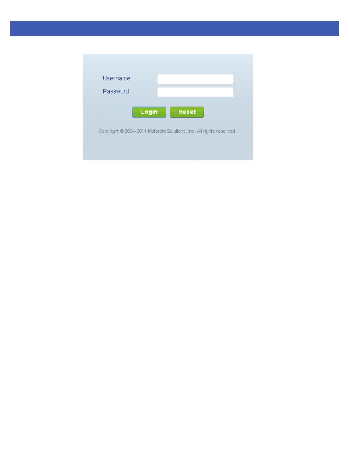
Figure 2-1 Access Point Web UI Login Screen
5. Enter the default username admin in the Username field.
6. Enter the default password motorola in the Password field.
Web UI Features 2 - 3
7. Select the Login button to load the management interface.
If this is the first time the management interface has been accessed, the first screen to display will prompt for a change
of the default access point password. Then, a dialogue displays to start the initial setup wizard. For more information
on using the initial setup wizard see Using the Initial Setup Wizard on page 3-2.
Page 20
2 - 4 WiNG 5 Access Point System Reference Guide
2.2 Icon Glossary
The access point interface utilizes a number of icons designed to interact with the system, gather information from
managed devices and obtain status. This chapter is a compendium of the icons used, and is organized as follows:
• Global Icons
• Dialog Box Icons
• Table Icons
• Status Icons
• Configurable Objects
• Configuration Objects
• Configuration Operation Icons
• Access Type Icons
• Administrative Role Icons
• Device Icons
2.2.1 Global Icons
Icon Glossary
This section lists global icons available throughout the interface.
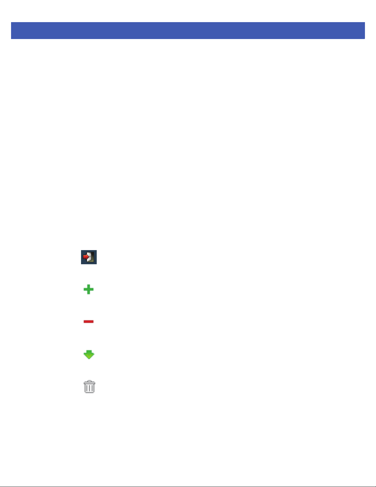
Logoff – Select this icon to log out of the system. This icon is always available and
is located at the top right-hand corner of the UI.
Add – Select this icon to add a row in a table. When this icon is selected, a new
row is created in the table, or a dialog box opens where you can enter values for
that particular list.
Delete – Select this icon to remove a row from a table. When this icon is clicked,
the selected row is immediately deleted.
More Information – Select this icon to display a pop-up with supplementary
information that may be available for an item.
Tras h – Select this icon to remove a row from a table. When this icon is clicked,
the selected row is immediately deleted.
Page 21

2.2.2 Dialog Box Icons
Icon Glossary
These icons indicate the current state of various controls in a dialog. These icons enables you to gather, at a glance, the
status of all the controls in a dialog. The absence of any of these icons next to a control indicates the value in that control
has not been modified from its last saved configuration.
Web UI Features 2 - 5
Create new policy – Select this icon to create a new policy. Policies define
different configuration parameters that can be applied to device configurations,
and device profiles.
Edit policy – Select this icon to edit an existing policy. To edit a policy, click on the
policy and select this button.
Entry Updated – Indicates a value has been modified from its last saved
configuration.
2.2.3 Table Icons
Icon Glossary
The following two override icons are status indicators for transactions that need to be committed.
Entry Update – States that an override has been applied to a device’s profile
configuration.
Mandatory Field – Indicates the control’s value is a mandatory configuration
item. You will not be allowed to proceed further without providing all
mandatory values in this dialog.
Error in Entry – Indicates there is an error in a value that has been entered in
that control. A small red popup provides a likely cause of the error.
Table Row Overridden – Indicates a change (profile configuration override)
has been made to a table row, and the change will not be implemented until
saved. This icon represents a change from this device’s profile assigned
configuration.
Table Row Added – Indicates a new row has been added to a table, and the
change will not be implemented until saved. This icon represents a change
from this device’s profile assigned configuration.
Page 22

2 - 6 WiNG 5 Access Point System Reference Guide
2.2.4 Status Icons
Icon Glossary
These icons define device status, operations on the wireless controller, or any other action that requires a status
being returned to the user.
Fatal Error – States there is an error causing a managed device to stop
functioning.
Error – Indicates an error exits requiring intervention. An action has failed, but
the error is not system wide.
Warning – States a particular action has completed, but some errors were
detected that did not stop the process from completing. Intervention might
still be required to resolve subsequent warnings.
Success – Indicates everything is well within the network or a process has
completed successfully without error.
Information – This icon always precedes information displayed to the user.
This may either be a message displaying progress for a particular process, or
may just be a message from the system.
2.2.5 Configurable Objects
Icon Glossary
These icons define configurable items within the UI.
Device Configuration – Represents a configuration file applicable to a device
category.
Auto Provisioning Policy – Represents an adoption policy as a set of
configuration parameters that define how wireless clients are adopted to the
access point.
Wireless LANs – States an action impacting a WLAN has occurred.
WLAN QoS Policy – States a quality of service (QoS) policy configuration has
been impacted.
Radio QoS Policy – Indicates a QoS policy configuration has been impacted.
Page 23
Web UI Features 2 - 7
AAA Policy – Indicates an Authentication, Authorization and Accounting
(AAA) policy has been impacted. AAA policies define RADIUS authentication
and accounting parameters.
Association ACL – Indicates an Association Access Control List (ACL)
configuration has been impacted. An ACL is a set of configuration parameters
used to set access to managed resources. The association ACL configures the
parameters for controlling device associations.
Smart RF Policy – States a Smart RF policy has been impacted. Smart RF
enables neighboring APs to take over for an AP that suddenly becomes
unavailable. This is accomplished by increasing the power of radios on nearby
APs to cover the hole created by the non-functioning AP.
Profile – States a device profile configuration has been impacted. A profile is
a collection of configuration parameters used to configure a device or a
feature.
Bridging Policy – Indicates a bridging policy configuration has been impacted.
A bridging policy defines which VLANs are bridged and how local VLANs are
bridged between the wired and wireless sides of the network.
RF Domain – States an RF Domain configuration has been impacted. RF
Domain implement location based security restrictions applicable to all
VLANs in a particular physical location.
Firewall Policy – Indicates a Firewall policy has been impacted. Firewalls
provide a barrier that prevent unauthorized access to secure resources while
allowing authorized access to external and internal resources.
IP Firewall Rules – Indicates an IP Firewall rule has been applied. An IP based
firewall rule implements firewall restrictions based on the IP address in a
received packet.
MAC Firewall Rules – States a MAC based Firewall Rule has been applied. A
MAC based firewall rule implements firewall restrictions based on the MAC
address in a received packet.
Wireless Client Role – Indicates a wireless client role has been applied to a
managed client. The role could be either sensor or client.
WIPS Policy – States the conditions of a WIPS policy have been invoked.
WIPS prevents unauthorized access to the network by checking for (and
removing) rogue APs and wireless clients.
Advanced WIPS Policy – States the conditions of an advanced WIPS policy
have been invoked. WIPS prevents unauthorized access to the system by
checking for and removing rogue access point’s and wireless clients.
Page 24
2 - 8 WiNG 5 Access Point System Reference Guide
Device Categorization – Indicates a device categorization policy is being
applied. This is used by the intrusion prevention system to categorize APs or
wireless clients as either neighbors or sanctioned devices. This enables these
devices to bypass the intrusion prevention system.
Captive Portal – States a captive portal is being applied. Captive portal is
used to provide hotspot services to wireless clients.
DNS Whitelist – A DNS whitelist is used in conjunction with captive portal to
provide hotspot services to wireless clients.
DHCP Server Policy – Indicates a DHCP server policy is being applied. DHCP
provides IP addresses to wireless clients. A DHCP server policy configures
how DHCP provides these IP addresses.
RADIUS Group – Indicates the configuration of RADIUS Group is being
defined and applied. A RADIUS group is a collection of RADIUS users with the
same set of permissions.
RADIUS User Pools – States a RADIUS user pool is being applied. RADIUS
user pools are a set of IP addresses that can be assigned to an authenticated
RADIUS user.
RADIUS Server Policy – Indicates a RADIUS server policy is being applied.
RADIUS server policy is a set of configuration attributes used when a RADIUS
server is configured for AAA.
Management Policy – Indicates a management policy is being applied.
Management policies are used to configure access control, authentication,
traps and administrator permissions.
2.2.6 Configuration Objects
Icon Glossary
Configuration icons are used to define the following:
Configuration – Indicates an item capable of being configured by the access
point’s interface.
View Events / Event History – Defines a list of events. Select this icon to view
events or view the event history.
Core Snapshots – Indicates a core snapshot has been generated. A core
snapshot is a file that records the status of all the processes and memory
when a process fails.
Page 25
Panic Snapshots – Indicates a panic snapshot has been generated. A panic
snapshot is a file that records the status of all the processes and memory
when a failure occurs.
UI Debugging – Select this icon/link to view current NETCONF messages.
View UI Logs – Select this icon/link to view the different logs generated by
the user interface, FLEX and the error logs.
2.2.7 Configuration Operation Icons
Icon Glossary
The following icons are used to define configuration operations:
Revert – When selected, any changes made after the last saved configuration
are restored back to the last saved configuration.
Web UI Features 2 - 9
Commit – When selected, all changes made to the configuration are written
to the access point. Once committed, changes cannot be reverted.
Save – When selected, changes are saved to the access point’s configuration.
2.2.8 Access Type Icons
Icon Glossary
The following icons display a user access type:
Web UI – Defines a Web UI access permission. A user with this permission
is permitted to access an associated device’s Web UI.
Teln et – Defines a TELNET access permission. A user with this permission is
permitted to access an access point using TELNET.
Page 26
2 - 10 WiNG 5 Access Point System Reference Guide
SSH – Indicates a SSH access permission. A user with this permission is
permitted to access an access point device using SSH.
Console – Indicates a console access permission. A user with this permission
is permitted to access using the access point’s serial console.
2.2.9 Administrative Role Icons
Icon Glossary
The following icons identify the different administrative roles allowed on the system:
Superuser – Indicates superuser privileges. A superuser has complete access
to all configuration aspects of the access point to which they are connected.
System – States system user privileges. A system user is allowed to
configure some general settings like boot parameters, licenses, auto install,
image upgrades etc.
Network – Indicates network user privileges. A network user is allowed to
configure all wired and wireless parameters, like IP configuration, VLANs,
L2/L3 security, WLANs, radios etc.
Security – Indicates security user privileges. A security level user is allowed
to configure all security related parameters.
Monitor – Defines a monitor role. This role provides no configuration
privileges. A user with this role can view all system configuration but cannot
modify them.
Help Desk – Indicates help desk privileges. A help desk user is allowed to use
troubleshooting tools like sniffers, execute service commands, view or
retrieve logs and reboot an access point.
Web User – Indicates a Web user privilege. A Web user is allowed accessing
the access point’s Web user interface.
Page 27

2.2.10 Device Icons
Icon Glossary
The following icons indicate the different device types managed by the system:
Web UI Features 2 - 11
System – This icon indicates system-wide impact.
Cluster – This icon indicates a cluster. A cluster is a set of access points that
work collectively to provide redundancy and load sharing.
Access Point – This icon indicates any access point that is a part of the
network.
Wireless Client – This icon defines any wireless client connected within the
access point managed network.
Page 28

2 - 12 WiNG 5 Access Point System Reference Guide
Page 29

CHAPTER 3 QUICK START
Access points can utilize an initial setup wizard to streamline the process of initially accessing the wireless network. The
wizard defines the access point’s operational mode, deployment location, basic security, network and WLAN settings. For
instructions on how to use the initial setup wizard, see Using the Initial Setup Wizard on page 3-2.
Page 30
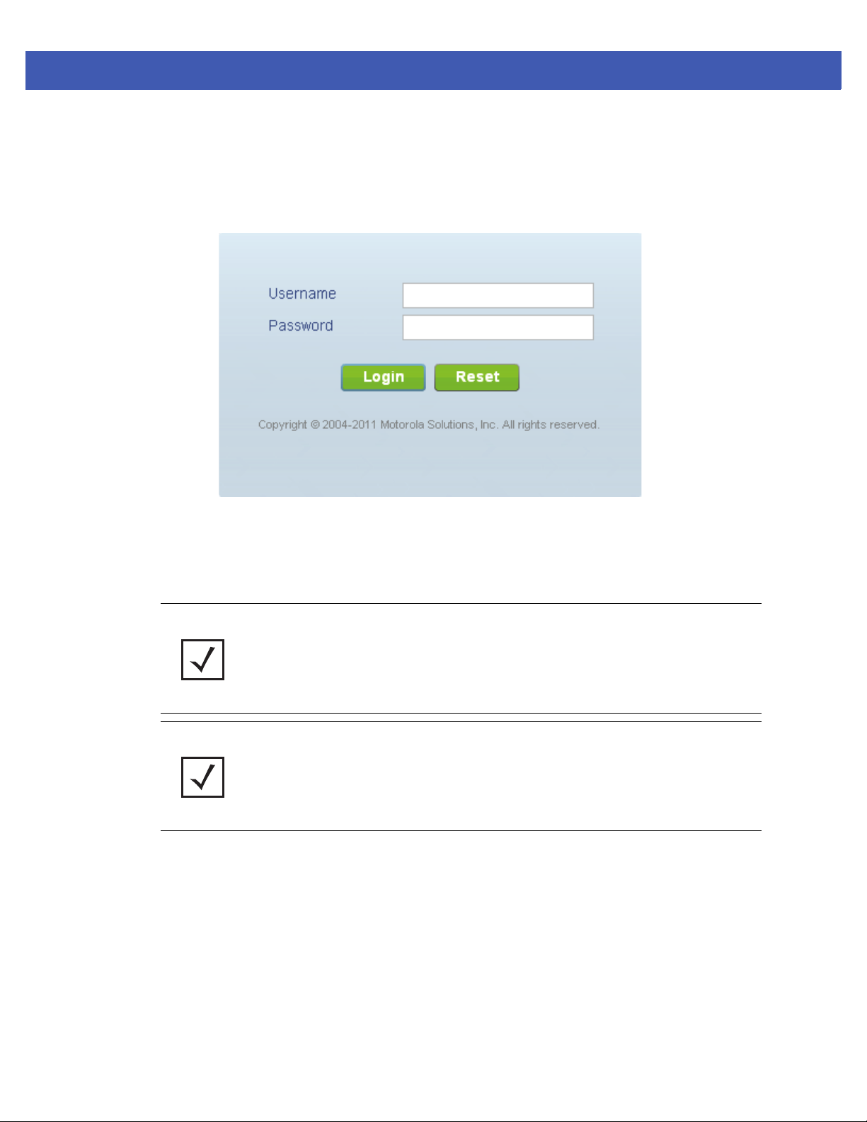
3 - 2 WiNG 5 Access Point System Reference Guide
3.1 Using the Initial Setup Wizard
Once the access point is installed and powered on, complete the following steps to get the access point up and
running and access management functions:
1. Point the Web browser to the access point’s IP address. The following login screen displays:
Figure 3-1 Web UI Login Screen
2. Enter the default username admin in the Username field.
3. Enter the default password motorola in the Password field.
4. Click the Login button to load the management interface.
NOTE: When logging in for the first time, you’re prompted to change the password to
enhance device security in subsequent logins.
NOTE: If you get disconnected when running the wizard, you can connect again with the
access point’s actual IP address (once obtained) and resume the wizard.
Page 31
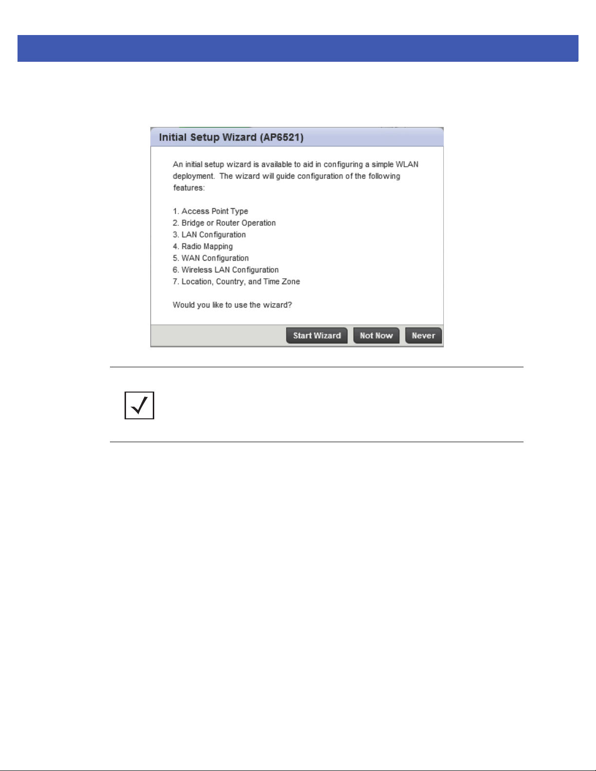
Quick Start 3 - 3
If this is the first time the access points’ management interface has been accessed, an introductory screen displays
that outlines the parameters that can be configured sequentially using the setup wizard.
Figure 3-2 Initial Setup Wizard
NOTE: The Initial Setup Wizard displays the same pages and content for each access
point model supported. The only difference being the number of radios configurable by
model, as an AP-7131 model can support up to three radios, AP-6532 and AP-7161
models support two radios and AP-6521 and AP6511 models support a single radio.
1. Select Start Wizard to run the setup wizard. You can bypass the setup wizard and move directly to access point’s main
user interface (UI) by selecting Not Now. The setup wizard can also be disabled until the next time the access point
is rebooted by selecting Never.
Page 32
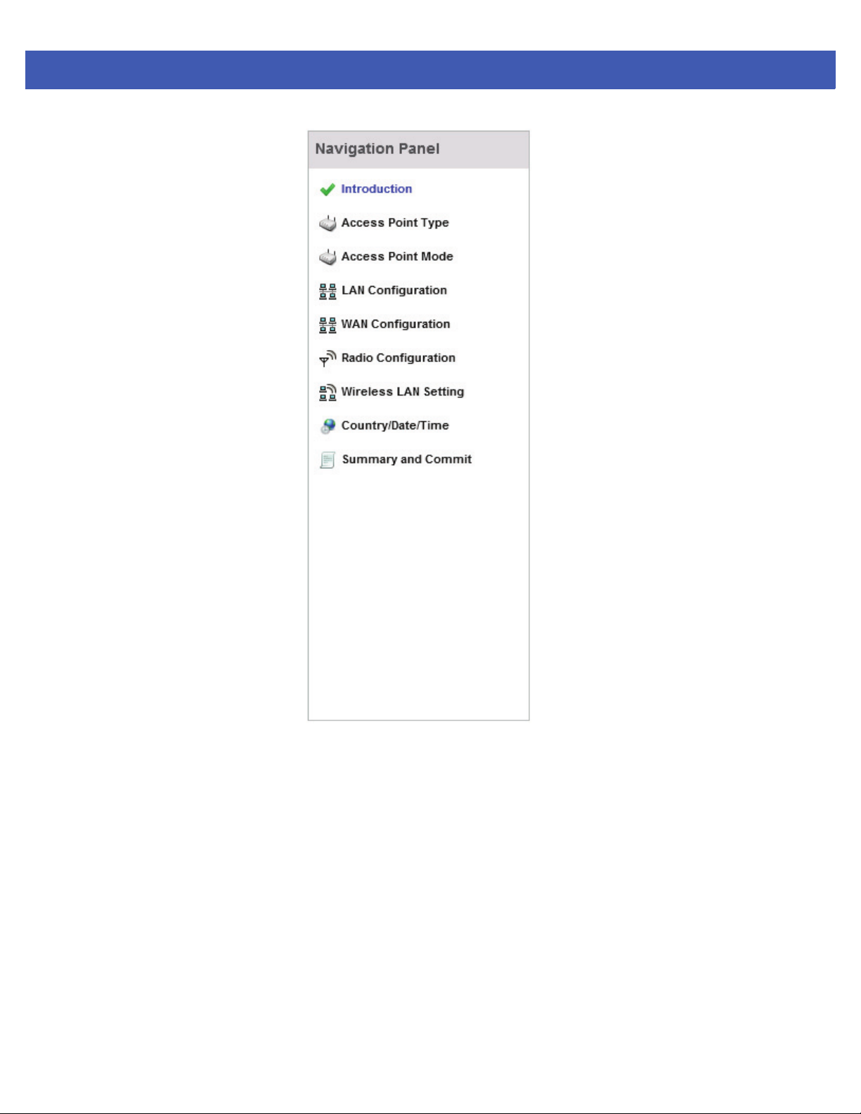
3 - 4 WiNG 5 Access Point System Reference Guide
Figure 3-3 Initial Setup Wizard - Navigation Panel
The first page of the Initial AP Setup Wizard displays the Navigation Panel and Introduction for the configuration
activities comprising the access point's initial setup.
A green checkmark to the left of an item in the Navigation Panel defines the listed task as having its minimum
required configuration parameters set correctly. A red X defines the task as still requiring at least one parameter
be defined correctly.
Page 33
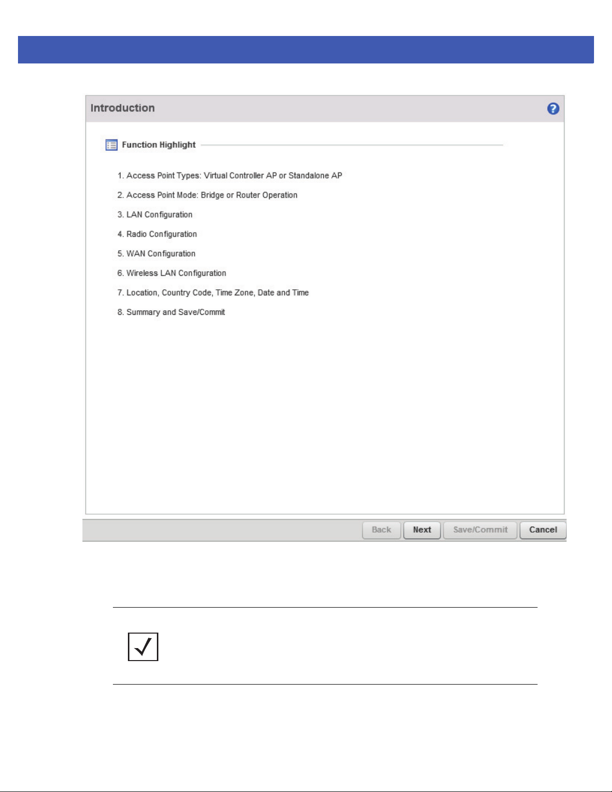
Quick Start 3 - 5
Figure 3-4 Initial Setup Wizard - Introduction
5. Select Save/Commit within each page to save the updates made to that page's configuration. Select Next to proceed
to the next page listed in the Navigation Panel. Select Back to revert to the previous screen in the Navigation Panel
without saving your updates.
NOTE: While you can navigate to any page in the navigation panel, you cannot complete
the Initial AP Setup Wizard until each task in the Navigation Panel has a green
checkmark.
6. Select Next. The Initial AP Setup Wizard displays the Access Point Type screen to define the access point's
Standalone versus Virtual Controller AP functionality and the way the access point is adopted to a controller.
Page 34
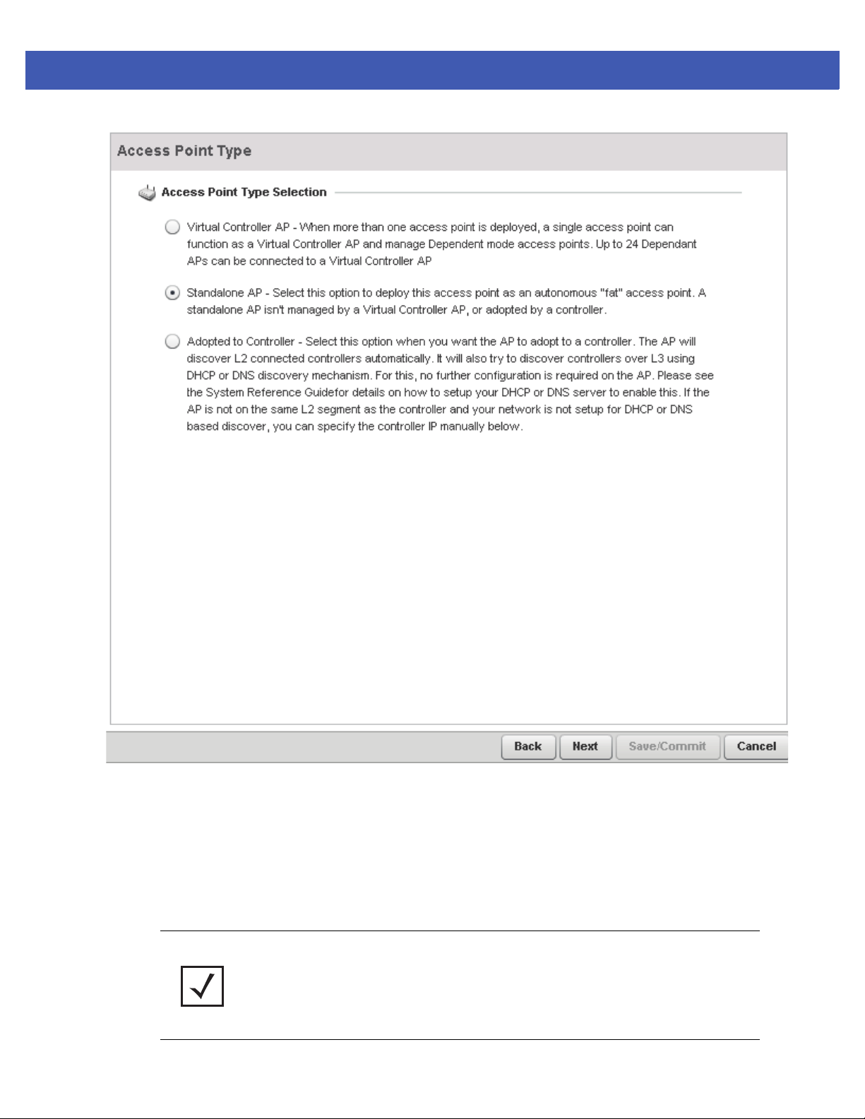
3 - 6 WiNG 5 Access Point System Reference Guide
Figure 3-5 Initial Setup Wizard - Access Point Type
7. Select an Access Point Type from the following options.
• Virtual Controller AP - When more than one access point is deployed, a single access point can function as a
Virtual Controller AP. Up to 24 access points can be connected to, and managed by, a single Virtual Controller
AP of the same model.
• Standalone AP -Select this option to deploy this access point as an autonomous fat access point. A standalone
AP isn't managed by a Virtual Controller AP, or adopted by a RFS series controller.
NOTE: If designating the access point as a Standalone AP, Motorola Solutions
recommends the access point’s UI be used exclusively to define its device configuration,
and not the CLI. The CLI provides the ability to define more than one profile and the UI
does not. Consequently, the two interfaces cannot be used collectively to manage profiles
without an administrator encountering problems.
Page 35
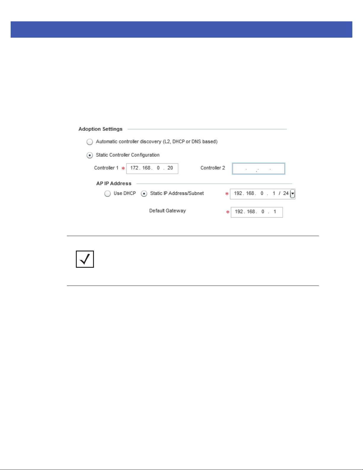
Quick Start 3 - 7
• Adopted to Controller - Select this option when deploying the access point as a controller managed (Dependent
mode) access point. Selecting this option closes the Initial AP Setup Wizard. An adopted access point obtains its
configuration from a profile stored on its managing controller. Any manual configuration changes are overwritten
by the controller upon reboot.
Select the Automatic controller discovery option to enable the access point to be discovered and adopted using
layer 2 settings. If preferring layer 3 adoption, select the Static Controller Configuration option, and define the
addresses of the preferred controllers. If using the static method, you’ll also need to define whether the access
point receives an IP address using DHCP or if IP resources are provided statically.
Figure 3-6 Initial Setup Wizard - Adoption Settings
NOTE: The best way to administer a network populated by numerous access points is to
configure them directly from the designated controller or Virtual Controller AP. If an
access point’s configuration requires an exception from the controller or Virtual Controller
AP’s assigned profile configuration, the administrator should apply a Device Override to
change just that access point’s configuration. For more information on applying an
override to an access point’s Virtual Controller AP assigned configuration profile, see
Profile Overrides on page 5-184.
8. Select Next. The Initial AP Setup Wizard displays the Access Point Mode screen to define the access point's routing
or bridging mode functionality.
Page 36
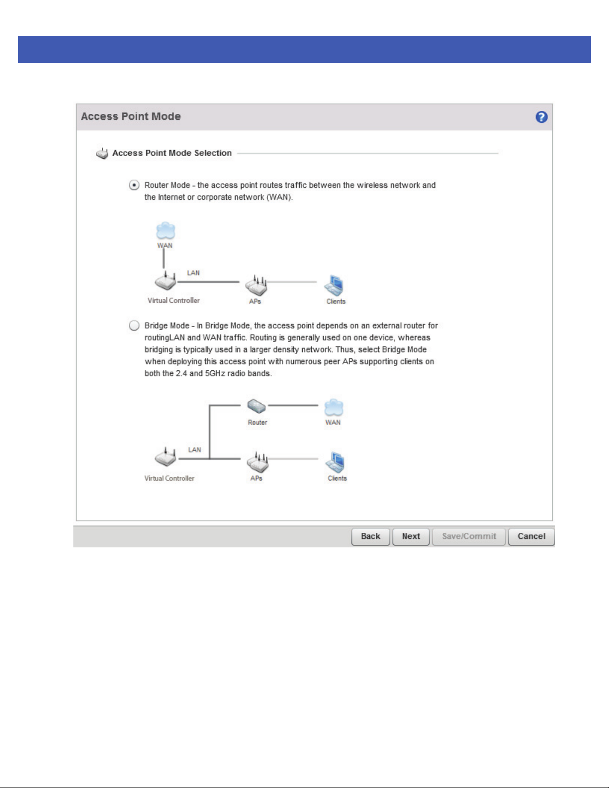
3 - 8 WiNG 5 Access Point System Reference Guide
Figure 3-7 Initial AP Setup Wizard - Access Point Mode
9. Select an Access Point Mode from the available options.
• Router Mode - In Router Mode, the access point routes traffic between the local network (LAN) and the Internet
or external network (WAN). Router mode is recommended in a deployment supported by just a single access
point.
• Bridge Mode - In Bridge Mode, the access point depends on an external router for routing LAN and WAN traffic.
Routing is generally used on one device, whereas bridging is typically used in a larger density network. Thus,
select Bridge Mode when deploying this access point with numerous peer APs supporting clients on both the
2.4 and 5GHz radio bands.
10.Select Next. The Initial AP Setup Wizard displays the LAN Configuration screen to set the access point's LAN
interface configuration.
Page 37
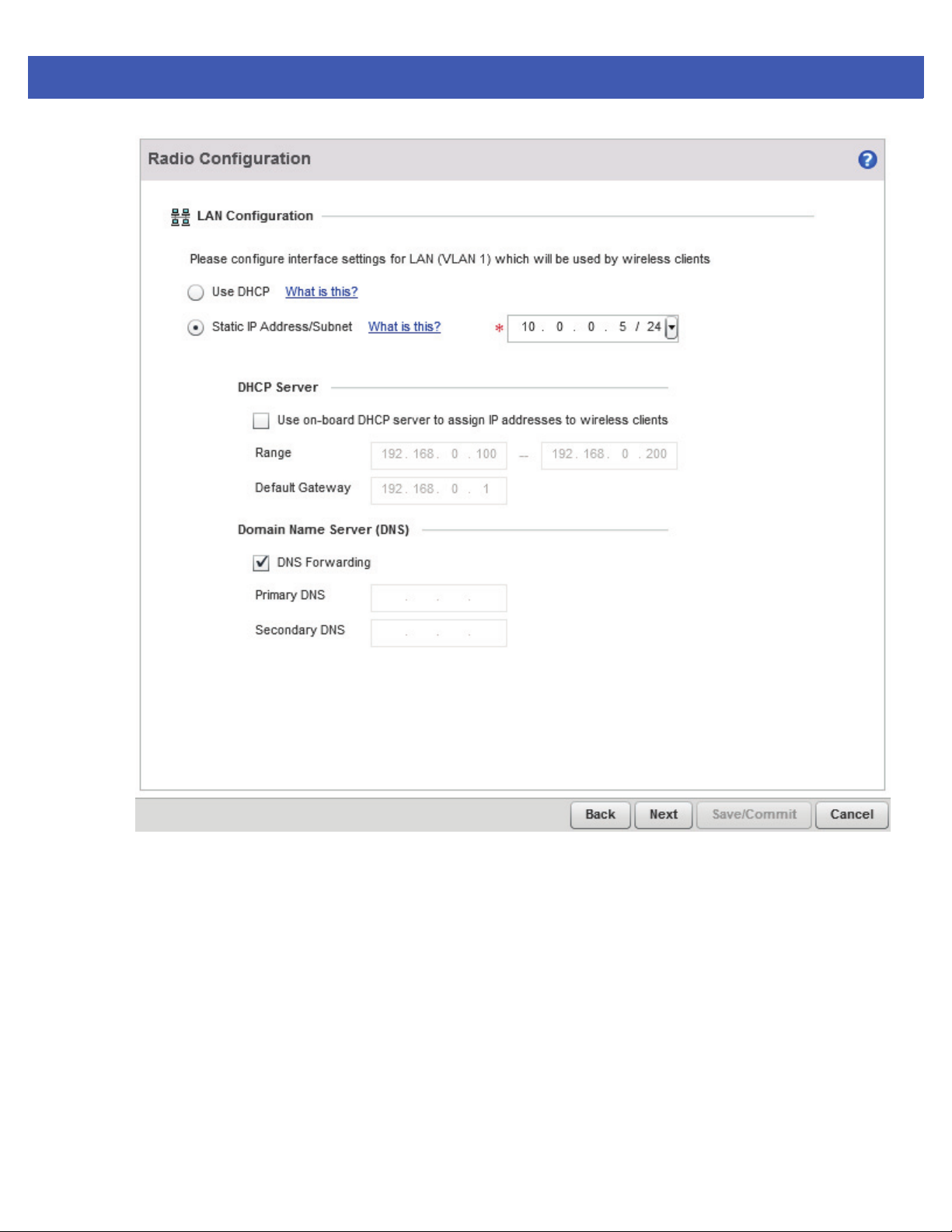
Quick Start 3 - 9
Figure 3-8 Initial AP Setup Wizard - LAN Configuration
11.Set the following DHCP and Static IP Address/Subnet information for the LAN interface:
• Use DHCP - Select the checkbox to enable an automatic network address configuration using the access point’s
DHCP server. AP-6511 and AP-6521 model access points do not have an onboard DHCP server and an external DHCP
server must be utilized.
• Static IP Address/Subnet - Enter an IP Address and a subnet for the access point's LAN interface. If Use DHCP is
selected, this field is not available. When selecting this option, define the following DHCP Server and Domain Name
Server (DNS) resources, as those fields will become enabled on the bottom portion of the screen.
• Use on-board DHCP server to assign IP addresses to wireless clients -Select the checkbox to enable the access
point’s DHCP server to provide IP and DNS information to clients on the LAN interface.
• Range - Enter a starting and ending IP Address range for client assignments on the access point's LAN interface.
Avoid assigning IP addresses from x.x.x.1 - x.x.x.10 and x.x.x.255, as they are often reserved for standard network services. This is a required parameter.
• Default Gateway - Define a default gateway address for use with the default gateway. This is a required
parameter.
Page 38
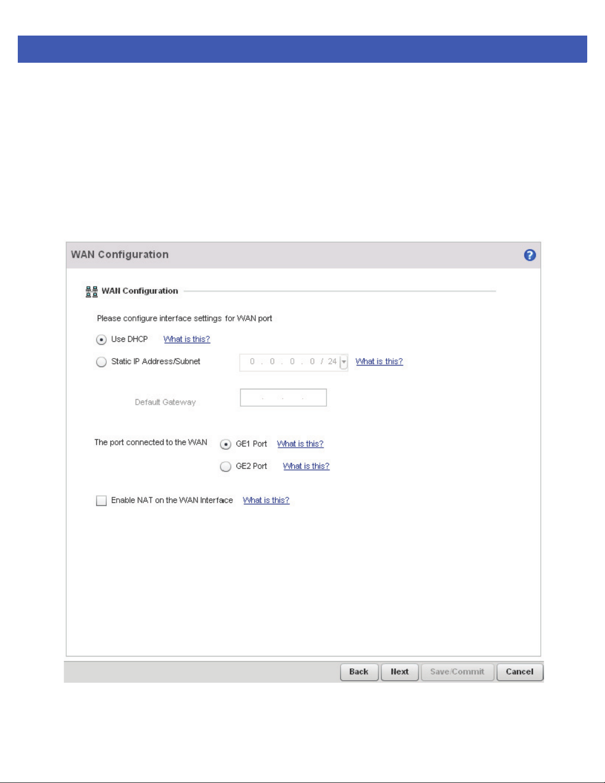
3 - 10 WiNG 5 Access Point System Reference Guide
• DNS Forwarding - Select this option to allow a DNS server to translate domain names into IP addresses. If this
option is not selected, a primary and secondary DNS resource must be specified. DNS forwarding is useful
when a request for a domain name is made but the DNS server, responsible for converting the name into its
corresponding IP address, cannot locate the matching IP address.
• Primary DNS - Enter an IP Address for the main Domain Name Server providing DNS services for the access
point's LAN interface.
• Secondary DNS - Enter an IP Address for the backup Domain Name Server providing DNS services for the
access point's LAN interface
12.Select Next. The Initial AP Setup Wizard displays the WAN Configuration screen to set the access point's WAN
interface configuration.
Figure 3-9 Initial AP Setup Wizard - WAN Configuration
Page 39
Quick Start 3 - 11
13.Set the following DHCP and Static IP Address/Subnet information for the WAN interface:
• Use DHCP - Select the checkbox to enable an automatic network address configuration using the access point’s
DHCP server. AP-6511 and AP-6521 model access points do not have an onboard DHCP server and an external DHCP
server must be utilized.
• Static IP Address/Subnet - Enter an IP Address/Subnet and gateway for the access point's WAN interface. These
are required fields
• The port connected to the WAN - Select the port used as the physical access point connection to the external
network. This ports available differ depending on the access point model deployed. Access point models with a
single port have this option fixed.
• Enable NAT on the WAN Interface - Select the checkbox to allow traffic to pass between the access point's WAN
and LAN interfaces.
14.Select Next. The Initial AP Setup Wizard displays the Radio Configuration screen to define radio support for the
2.4GHz radio band, 5GHz radio band or to set the radio's functionality as a dedicated sensor.
NOTE: The Radio Configuration screen displays separate configurable fields for each
access point radio. Supported access point models can have from one to three (AP-7131)
radios. The ADSP Sensor Support field displays at the bottom of the screen only if a
radio has been dedicated as a sensor.
Page 40
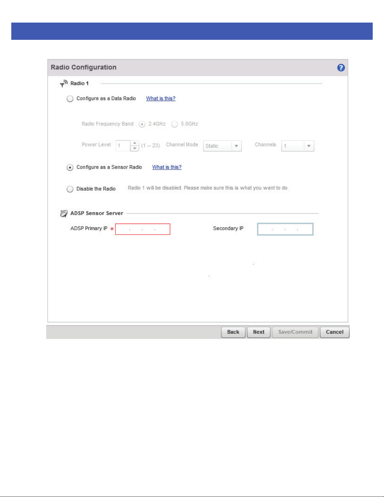
3 - 12 WiNG 5 Access Point System Reference Guide
Figure 3-10 Initial AP Setup Wizard - Radio Configuration
15.Set the following parameters for each radio:
• Configure as a Date Radio - Select this option to dedicate this radio for WLAN client support in either the
selected 2.4 or 5GHz radio band.
• Radio Frequency Band - Select either the 2.4GHz or 5.0GHz radio band to use with the radio when selected
as a Data Radio. The selected band is used for WLAN client support. Considers selecting one radio for
2.4GHz and another for 5GHz support (if using a dual or three radio model) when supporting clients in both
the 802.11bg and 802.11n bands.
• Power Level - Use the spinner control to select a 1 - 23 dBm minimum power level to assign to this radio in
selected 2.4 or 5.0 GHz band. 1 dBm is the default setting.
• Channel Mode - Select either Random, Best or Static. Select Random for use with a 802.11a/n radio. To
comply with Dynamic Frequency Selection (DFS) requirements in the European Union, the 802.11a/n radio
uses a randomly selected channel each time the access point is powered on. Select Best to enable the access point to scan non-overlapping channels and listen for beacons from other access points. After the
Page 41
Quick Start 3 - 13
channels are scanned, it will select the channel with the fewest access points. In the case of multiple access
points on the same channel, it will select the channel with the lowest average power level. When Constantly
Monitor is selected, the access point will continuously scan the network for excessive noise and sources of
interference. Select Static to assign the access point a permanent channel and scan for noise and interference
only when initialized.
• Configure as a Sensor Radio - Select this option to dedicate the radio to sensor support exclusively. When
functioning as a sensor, the radio scans in sensor mode across all channels within the 2.4 and 5.0GHz bands to
identify potential threats within the access point managed network. If dedicating a radio as a sensor resource, a
primary and secondary ADSP server must be specified as an ADSP management resource.
NOTE: If configuring an AP-6511 or AP-6521 model access point as a sensor, the access
point will require a reboot before its sensor functionality is invoked. The reboot can take
place at the completion of the Initial AP Setup Wizard.
• Disable the Radio - Select this option to disable this radio, thus prohibiting it from either providing WLAN or sensor
support. Verify this course action with your network administrator before rendering the radio offline.
16.Select Next. The Initial AP Setup Wizard displays the Wireless LAN Setting screen to define network address and
security settings for two WLAN configurations available to the access point as part of the Initial AP Setup Wizard.
Once the access point has an initial configuration defined, numerous additional WLAN configurations can be set.
Page 42
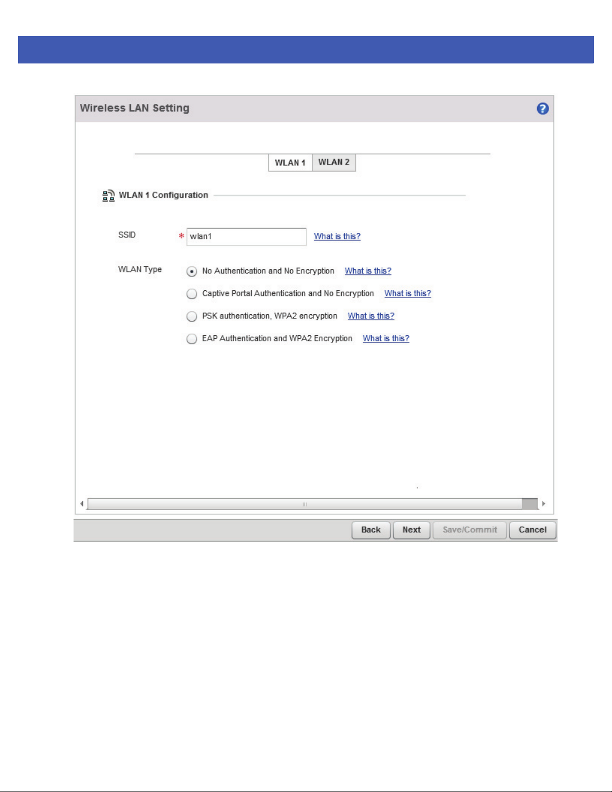
3 - 14 WiNG 5 Access Point System Reference Guide
Figure 3-11 Initial AP Setup Wizard - Wireless LAN Setting
17.Set the following parameters for each if the WLAN configurations available as part of this Initial AP Setup
Wizard:
• SSID - Enter or modify the Services Set Identification (SSID) associated with the WLAN. The WLAN name is
auto-generated using the SSID until changed by the user. The maximum number of characters is 32. Do not use
< > | “ & \ ? , This is a required parameter for each WLAN.
• WLAN Type - Set the data protection scheme used by clients and access points within the WLAN. The following
options are available:
• No Authentication and no Encryption - Select this option to provide no security between the access point
and connected clients on this WLAN.
• Captive Portal Authentication and No Encryption - Select this option to use a Web page (either internally or
externally hosted) to authenticate users before access is granted to the network. If using this option, define
whether a local or external RADIUS authentication resource is used.
Page 43
Quick Start 3 - 15
• PSK Authentication and WPA2 Encryption - Select the option to implement a pre-shared key that must be cor-
rectly shared between the access point and requesting clients using this WLAN. If using this option, specify a
WPA key in either ASCII (8-63 characters) or HEX (64 characters) format.
• EAP Authentication and WPA2 Encryption - Select this option to authenticate clients within this WLAN through
the exchange and verification of certificates. If using this option, define whether a local or external RADIUS authentication resource is used.
• WPA Key - If a WPA key is required (PSK Authentication and WPA2 Encryption), enter an alphanumeric string of 8
to 63 ASCII characters or 64 HEX characters as the primary string both transmitting and receiving authenticators
must share. The alphanumeric string allows character spaces. This passphrase saves the administrator from
entering the 256-bit key each time keys are generated.
• RADIUS Server - If the WLAN type requires a RADIUS server to validate user credentials, designate whether the
access point is using an External RADIUS Server resource or the access point's own Onboard RADIUS Server.
If using an external RADIUS server resource, provide the IP address of the external server and the shared secret
used to authenticate the request.
NOTE: If using the access point’s onboard RADIUS server, an additional RADIUS Server
Configuration screen displays within the Navigation Panel on the left-hand side of the
screen. Use this screen to create user accounts validated when the access point
authenticates client connection requests to the onboard RADIUS server. AP-6511 and
AP-6521 model access point’s do not have an onboard RADIUS server resource and an
external RADIUS server resource must be utilized.
18.Select Next. The Initial AP Setup Wizard displays the RADIUS Server Configuration screen if the access point’s
onboard RADIUS server is required to validate user requests. If an onboard RADIUS server is not required, the Initial
AP Setup Wizard displays the Country/Date/Time screen to set device deployment, administrative contact and
system time information.
Page 44
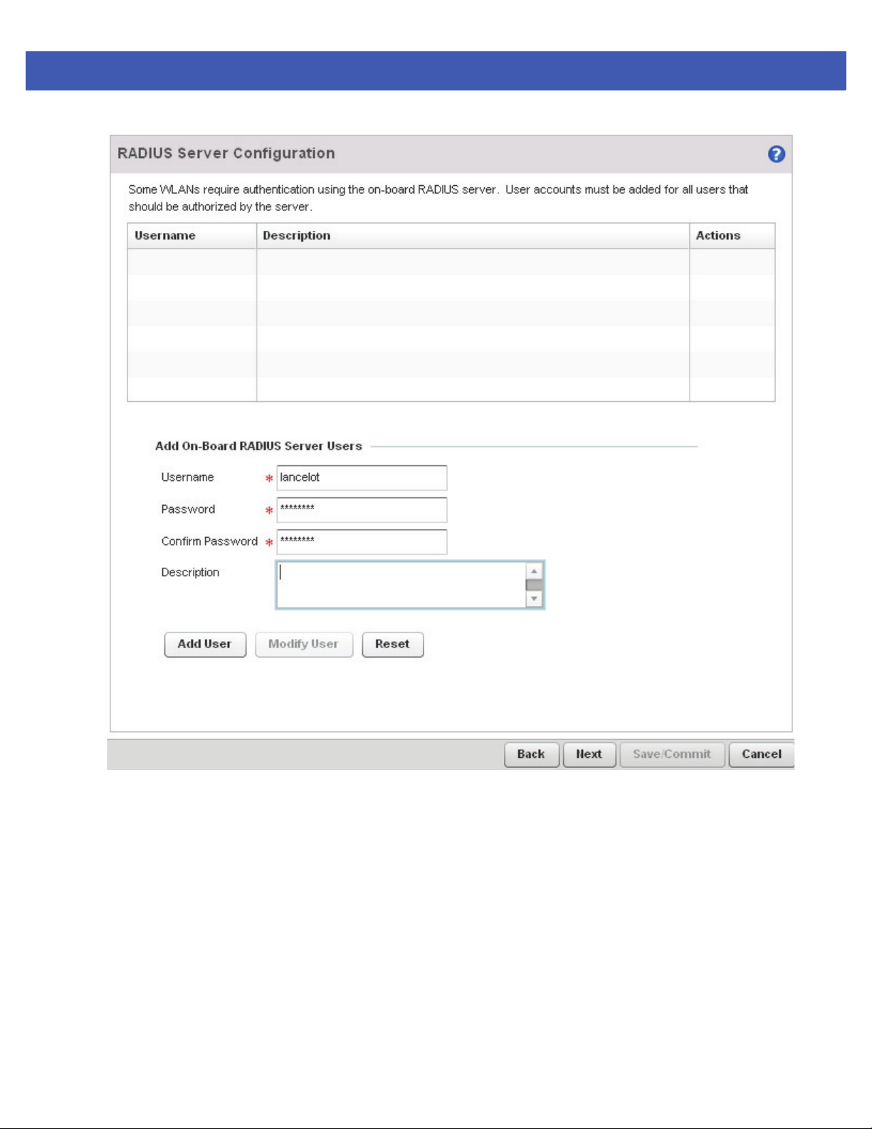
3 - 16 WiNG 5 Access Point System Reference Guide
Figure 3-12 Initial AP Setup Wizard - RADIUS Server Configuration
19.Refer to the Username, Password, Description and Actions columns to review credentials of existing RADIUS
Server user accounts. Add new accounts or edit the properties of existing accounts as updates are required.
20.Refer to the Add On-Board RADIUS Server Users field to set the following parameters for a user account:
• Username - If adding a new user account, create a username up to X characters in length. The username cannot
be revised if modifying the user configuration. This is a required parameter.
• Password - Provide (or modify) a password between X - X characters in length entered each time a requesting
client attempts access to the AP managed network using the access point's onboard RADIUS server. This is a
required parameter.
• Confirm Password - Re-enter (or modify) the password as a means of confirming the password. This is a
required parameter.
• Description - Optionally provide a description of the user account as means of further differentiating it from
others.
Page 45
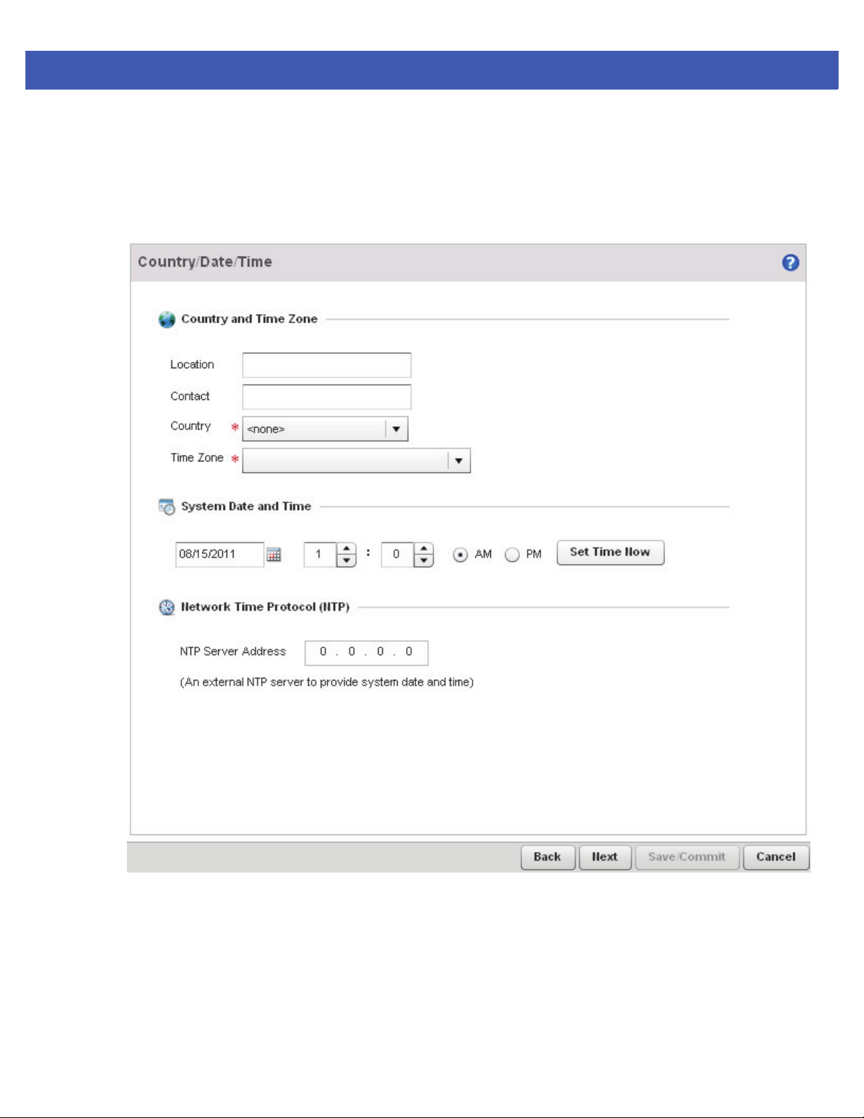
Quick Start 3 - 17
21.When completed, select Add User to commit a new user, Modify User to commit a modified user or Reset to clear
the screen without updating the configuration. Selecting Reset clears the field of all entered user account information.
22.Select Next. The Initial AP Setup Wizard displays the Country/Date/Time screen to set device deployment,
administrative contact and system time information. The system time can either be set manually or be supplied by a
dedicated Network Time Protocol (NTP) resource.
Figure 3-13 Initial AP Setup Wizard - Country/Date/Time
23.Refer to the Country and Time Zone field to set the following device deployment information:
• Location - Define the location of the access point. The Location parameter acts as a reminder of where the AP can
be located within the Motorola Solutions managed wireless network.
• Contact - Specify the contact information for the administrator. The credentials provided should accurately reflect
the individual responding to service queries.
Page 46

3 - 18 WiNG 5 Access Point System Reference Guide
• Country - Select the Country where the access point is deployed. The access point prompts for the correct
country code on the first login. A warning message also displays stating an incorrect country setting may result
in illegal radio operation. Selecting the correct country is central to legal operation. Each country has its own
regulatory restrictions concerning electromagnetic emissions and the maximum RF signal strength that can be
transmitted. This is a required parameter.
• Time Zone - Set the time zone where the access point is deployed. This is a required parameter. The setting
should be complimentary with the selected deployment country.
24. If an NTP resource is unavailable, set the System Date and Time (calendar date, time and AM/PM designation).
25.Optionally enter the IP address of a server used to provide system time to the access point. Once the IP address
is entered, the Network Time Protocol (NTP) functionality is engaged automatically for synchronization with
the NTP resource.
26. If an NTP resource is unavailable, set the System Date and Time (calendar date, time and AM/PM designation).
27.Optionally enter the IP address of a server used to provide system time to the access point. Once the IP address
is entered, the Network Time Protocol (NTP) functionality is engaged automatically for synchronization with
the NTP resource.
28.Select Next. The Initial AP Setup Wizard displays the Summary and Commit screen to summarize the screens
(pages) and settings updated using the Initial AP Setup Wizard.
There's no user intervention or additional settings required within this screen. Its an additional means of
validating the configuration before its deployed. However, if a screen displays settings not intended as part of the
initial configuration, the screen can be selected from within the Navigation Panel and its settings modified
accordingly.
Page 47
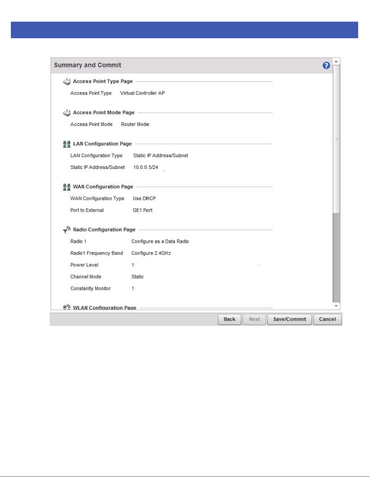
Quick Start 3 - 19
Figure 3-14 Initial AP Setup Wizard - Summary and Commit
29.If the configuration displays as intended, select the Save/Commit button to implement these settings to the access
point’s configuration. If additional changes are warranted based on the summary, either select the target page from
the Navigational Panel, or use the Back button.
Page 48

3 - 20 WiNG 5 Access Point System Reference Guide
Page 49

CHAPTER 4 DASHBOARD
The dashboard allows network administrators to review and troubleshoot the operation of the devices comprising the
access point managed network. Use the dashboard to review the current network topology, assess the network’s
component health and diagnose problematic device behavior.
By default, the Dashboard screen displays the System Dashboard, which is the top level in the device hierarchy.
The dashboard provides the following tools and diagnostics:
• Dashboard
• Network View
Page 50
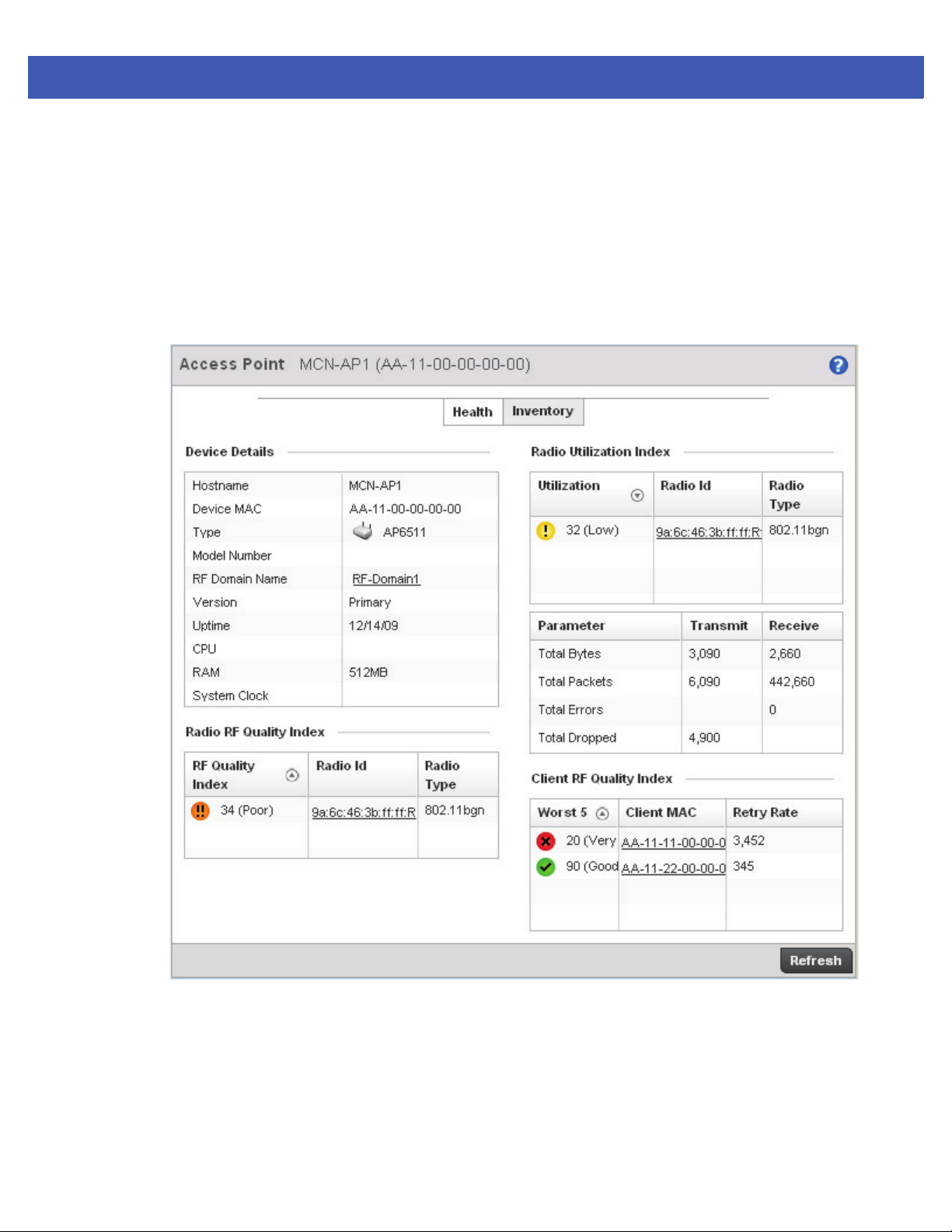
4 - 2 WiNG 5 Access Point System Reference Guide
4.1 Dashboard
The Dashboard displays device information organized by device association and inter-connectivity between an access
point and connected wireless clients.
To review dashboard information:
1. Select Dashboard. Expand the System menu item on the upper, left-hand, side of the UI and select either an access
point or connected client.
The Dashboard displays the Health tab by default.
4.1.1 Dashboard Conventions
The Dashboard displays device information using the following conventions:
• Health – Displays information about the state of the access point managed network.
• Inventory – Displays information on the physical devices being managed by the access point.
Figure 4-1 Dashboard screen - Health tab
Page 51
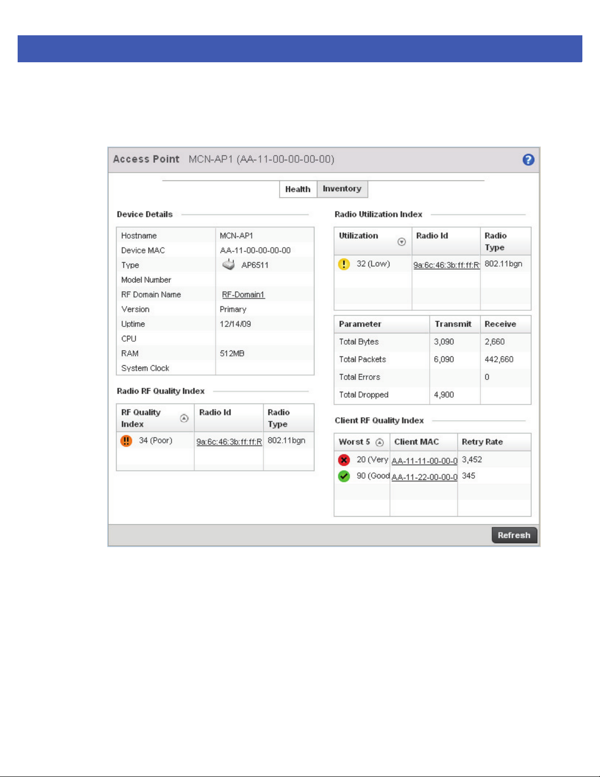
4.1.1.1 Health
Dashboard Conventions
The Health tab displays information about the state of the access point managed network.
Dashboard 4 - 3
Information in this tab is classified as:
• Device Details
• Radio RF Quality Index
• Radio Utilization Index
• Client RF Quality Index
4.1.1.1.1 Device Details
Health
The Device Details field displays model and version information.
Figure 4-2 Dashboard screen - Health tab
Page 52
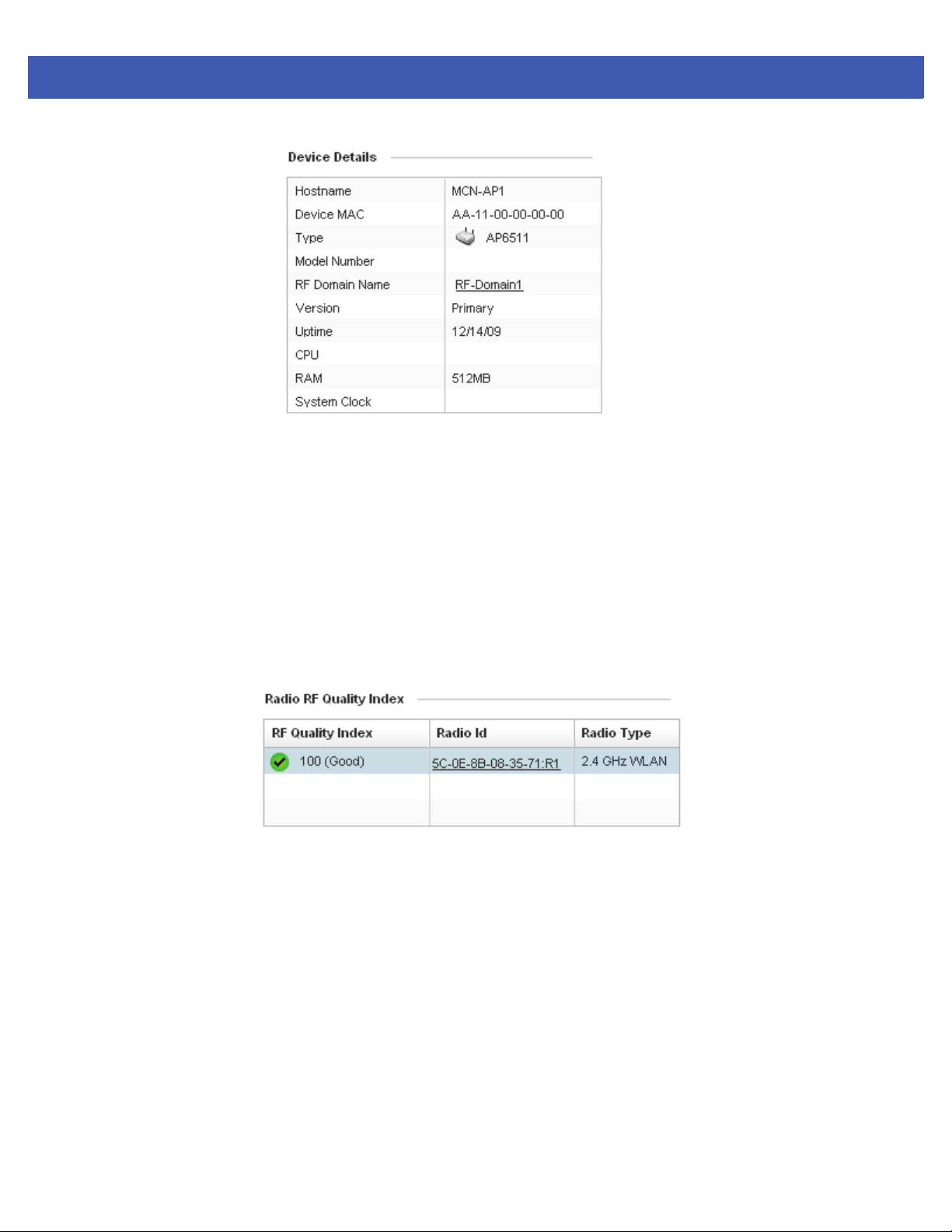
4 - 4 WiNG 5 Access Point System Reference Guide
Figure 4-3 Device Health
The Device Details field displays the name assigned to the selected access point, its factory encoded MAC address,
model type, RF Domain, software version, uptime, CPU and RAM information and system clock. Use this data to
determine whether a software upgrade is warranted, or if the system clock needs adjustment.
Periodically select Refresh (at the bottom of the screen) to update the data displayed.
4.1.1.1.2 Radio RF Quality Index
Dashboard Conventions
The Radio RF Quality Index field displays a RF quality table for the access point’s single default RF Domain. It’s a
percentage of the overall effectiveness of the RF environment. It’s a function of the data rate in both directions, the
retry rate and the error rate.
RF Quality displays as the average quality index for the single RF Domain utilized by the access point. The table lists
the bottom five (5) RF quality values for the RF Domain.
The quality is measured as:
• 0-20 – Very poor quality
• 20-40 – Poor quality
• 40-60 – Average quality
Figure 4-4 Radio RF Quality Index
• 60-100 – Good quality
The access point’s RF Domain allows an administrator to assign configuration data to multiple devices deployed in a
common coverage area, such as in a floor, building or site. The RF Domain contains policies that can determine a
Smart RF or WIPS configuration.
Use this diagnostic information to define measures to improve radio performance in respect to wireless client load
and radio band.
Page 53
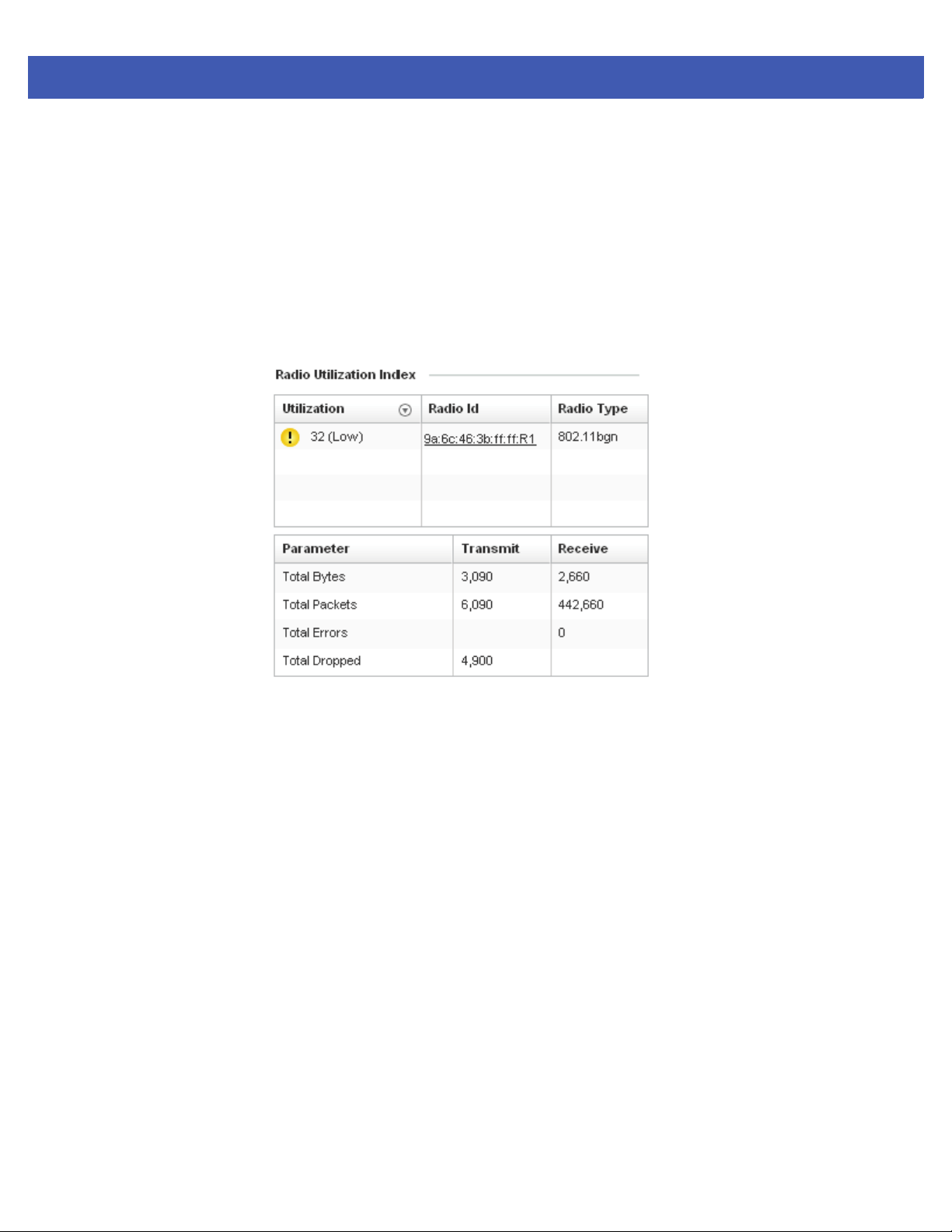
Periodically select Refresh (at the bottom of the screen) to update the RF quality data.
4.1.1.1.3 Radio Utilization Index
Dashboard Conventions
The Radio Utilization Index field displays how efficiently the RF medium is used by the access point. Traffic utilization
is defined as the percentage of throughput relative to the maximum possible throughput.
Refer to the number or errors and dropped packets to assess radio performance relative to the number of packets both
transmitted and received.
Periodically select Refresh (at the bottom of the screen) to update the radio utilization information displayed.
Dashboard 4 - 5
Figure 4-5 Radio Utilization Index field
Page 54
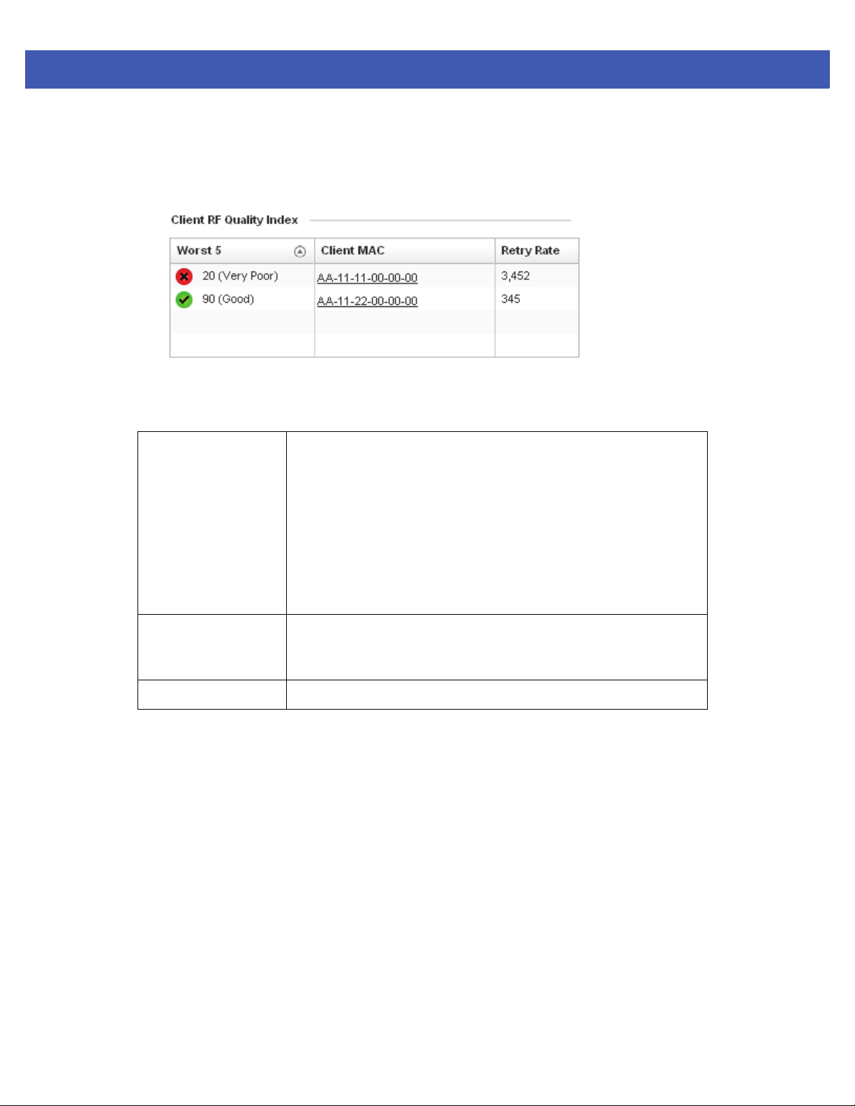
4 - 6 WiNG 5 Access Point System Reference Guide
4.1.1.1.4 Client RF Quality Index
Dashboard Conventions
The Client RF Quality field displays a list of the worst 5 performing clients managed by the selected access point.
Figure 4-6 Client RF Quality Index field
The Client RF Quality Index displays the following:
Worst 5
Lists the worst 5 performing client radios connected to the access point.
The RF Quality Index measures the overall effectiveness of the RF
environment as a percentage. Its a function of the connect rate in both
directions, as well as the retry rate and the error rate.
The quality is measured as:
• 0-20 – Very poor quality
• 20-40 – Poor quality
• 40-60 – Average quality
• 60-100 – Good quality
Client MAC Displays the factory encoded MAC address assigned to each connected
radio listed. Use this information to assist in the identification of poorly
performing radios.
Retry Rate
Lists the number of retries attempted to re-connect with the listed radio.
Periodically select Refresh (at the bottom of the screen) to update client RF quality.
Page 55
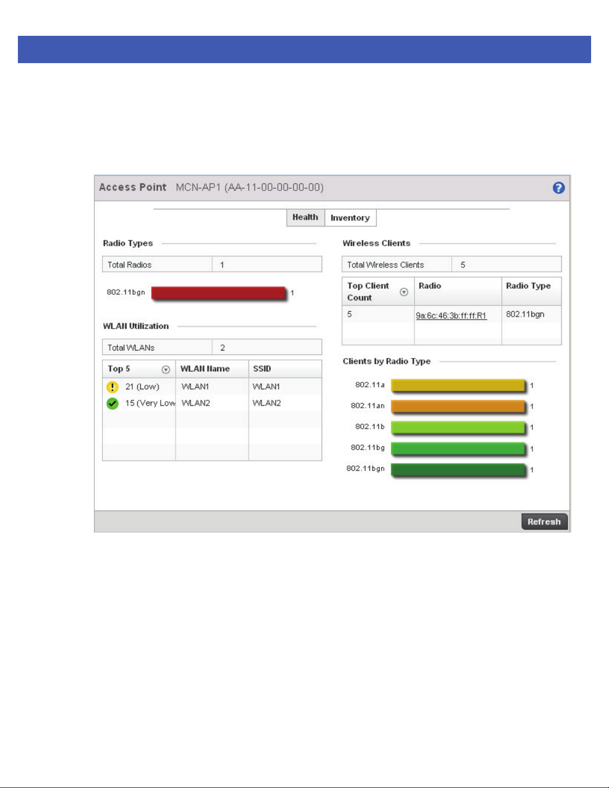
4.1.1.2 Inventory
Dashboard Conventions
The Inventory tab displays information relative to the devices managed by the selected access point. The Inventory screen
affords a system administrator an overview of the number and state of managed devices. The screen contains links to
display more granular data specific to a specific radio.
Dashboard 4 - 7
Figure 4-7 Dashboard screen - Inventory tab
The Inventory screen is partitioned into the following fields:
• Radio Types
• WLAN Utilization
• Wireless Clients
• Clients by Radio Type
Page 56
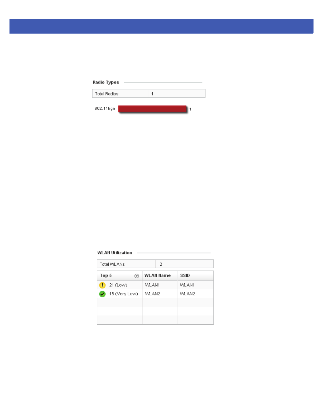
4 - 8 WiNG 5 Access Point System Reference Guide
4.1.1.2.5 Radio Types
Inventory
The Radio Types field displays the total number and types of radios managed by the selected access point.
Figure 4-8 Radio Types field
Refer to the Total Radios column to review the number of managed radios. Additionally, use the charts on the bottom
of the Radio Types field to assess the number WLANs utilized in supported radio bands.
Periodically select Refresh (at the bottom of the screen) to update the radio information.
4.1.1.2.6 WLAN Utilization
Inventory
The WLAN Utilization field displays the top 5 WLANs utilized by this access point in respect to client support. The
utilization index measures how efficiently the RF medium is utilized. It is defined as a percentage of the current
throughput relative to the maximum throughput possible.
The quality is measured as:
• 0-20 – Very low utilization
• 20-40 – Low utilization
• 40-60 – Moderate utilization
• 60 and above – High utilization
Figure 4-9 Device Types field
Periodically select Refresh (at the bottom of the screen) to update WLAN utilization information.
Page 57
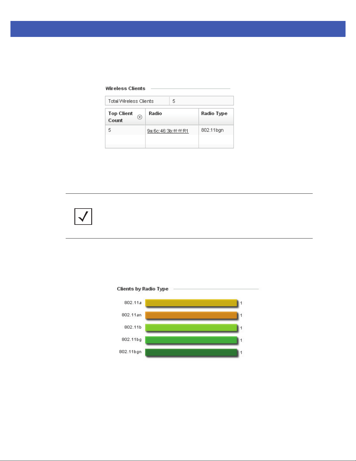
4.1.1.2.7 Wireless Clients
Inventory
The Wireless Clients field displays information about the wireless clients managed by the selected access point.
Information within the Wireless Clients field is presented in two tables. The first table lists the total number of wireless
clients managed by this access point. The second table lists an ordered ranking of radios based on their supported client
count. Use this information to assess if an access point managed radio is optimally deployed in respect to its radio type
and intended client support requirements.
Dashboard 4 - 9
Figure 4-10 Wireless Clients field
NOTE: AP-7131, AP-6532 and AP-7161 model access points can support up to 256 client
connections to a single access point. AP-6511 and AP-6521 model access points (both
single radio models) can support up to 128 client connections per access point.
4.1.1.2.8 Clients by Radio Type
Inventory
The Clients by Radio Type field displays a bar graph illustrating the number of connected clients currently operating on
supported radio bands.
For 5 GHz, clients are displayed supporting the 802.11a and 802.11an radio bands. For 2.4 GHz, clients are displayed
supporting the 802.11b, 802.11bg, and 802.11bgn radio bands. Use this information to determine if all the access point’s
client radio bands are optimally supported for the access point’s radio coverage area.
Figure 4-11 Client On Channel field
Page 58
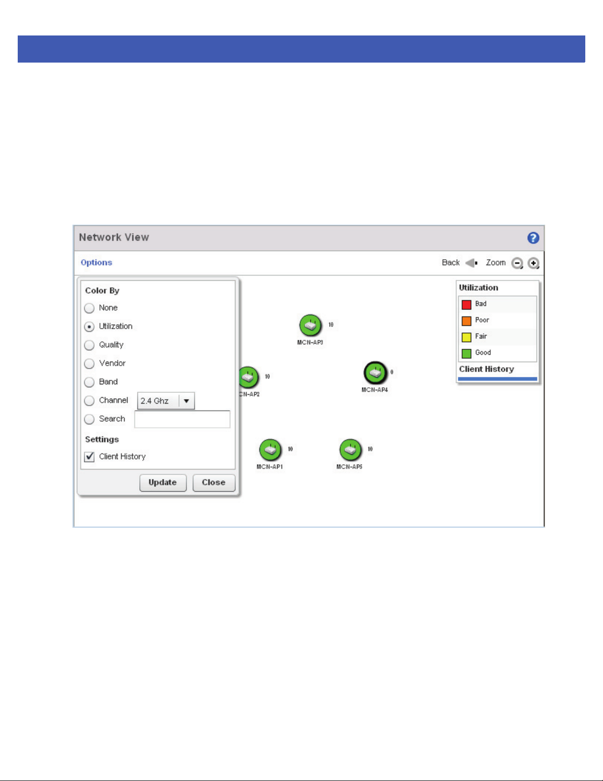
4 - 10 WiNG 5 Access Point System Reference Guide
4.2 Network View
The Network View displays device topology association between a selected access point, its RF Domain and its
connected clients. The association is displayed using a number of different color options.
Access points and clients can be selected and viewed using various color schemes in respect to neighboring access
points, connected devices and performance criteria. Display options can be utilized to review device performance and
utilization, as well as the RF band, channel and vendor. For more information, see Network View Display Options on
page 4-11.
To review a device’s Network Topology, select Dashboard > Network View.
Figure 4-12 Network View Topology
The left-hand side of the Network View display contains an expandable System Browser where access points can be
selected and expanded to display connected clients. Navigate the System Browser as required to review device
connections within the access point managed network. Many of these peer access points are available for connection
to access points in Virtual Controller AP mode.
Page 59
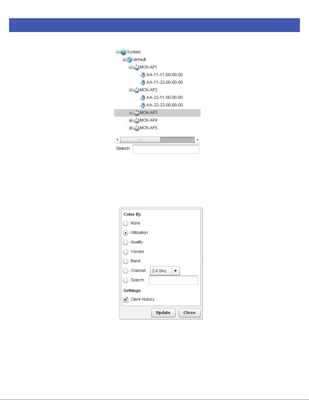
Figure 4-13 Network View - System Browser
Dashboard 4 - 11
4.2.1 Network View Display Options
Network View
1. Select the blue Options link right under the Network View banner to display a menu for different device interaction
display options.
Figure 4-14 Network View - Options
2. The following display filter options are available:
• None - Select this option to keep the Network View display as it currently appears, without any additional color or
device interaction adjustments.
• Utilization – Select this option to filter based on the percentage of current throughput relative to maximum
throughput. Utilization results include: Red (Bad Utilization), Orange (Poor Utilization), Yellow (Fair Utilization) and
Green (Good Utilization).
Page 60
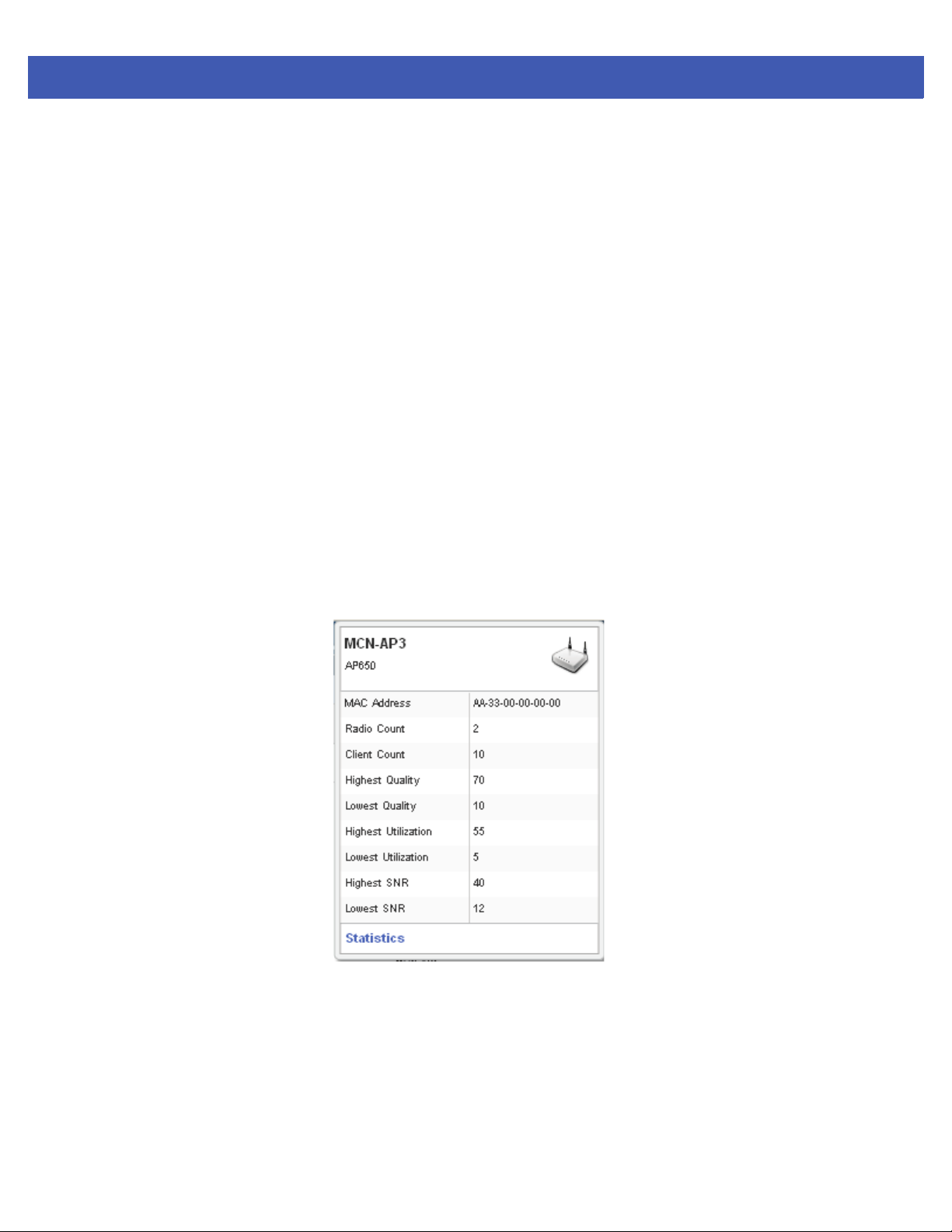
4 - 12 WiNG 5 Access Point System Reference Guide
• Quality – Select this option to filter based on the overall RF health. RF health is a ratio of connection rate, retry
rates, and error rates. Quality results include: Red (Bad Quality, Orange (Poor Quality), Yellow (Fair Quality) and
Green (Good Quality).
• Vendor – Displays the device manufacturer.
• Band – Select this option to filter based on the 2.4 or 5 GHz radio band of connected clients. Results include:
Yellow (2.4 GHz radio band) and Blue (5.GHz radio band). Selecting Band is a good way to determine whether
2.4 and 5 GHz radios are optimally deployed in respect to the access point client loads on both bands.
• Channel - Use the drop-down menu to filter whether device connections should be displayed in either the 2.4
or 5 GHz band.
• Search - Enter search criteria in the provided text field and select the Update button to isolate located
variables in blue within the Network View display.
3. Select the Update button to update the display with the changes made to the filter options. Select Close to close
the options field and remove it from the Network View.
4.2.2 Device Specific Information
Network View
A device specific information screen is available for individual devices selected from within the Network View (not
the System Browser). The screen displays the name assigned to the device, its model, factory encoded MAC address,
number or radios within the device, number of connected clients, as well as the highest and lowest reported Quality,
Utilization and Signal to Noise Ratio (SNR) This information cannot be modified by the administrator.
Figure 4-15 Device Specific Information
Optionally select the Statistics link at the bottom of the display a screen where Access Point device data can be
reviewed on a much more granular level. For more information, see Health on page 4-3.
Page 61

CHAPTER 5 DEVICE CONFIGURATION
Access points can either be assigned unique configurations to support a particular deployment objective or have an
existing RF Domain or Profile configuration modified (overridden) to support a requirement that deviates its configuration
from the configuration shared by its peer access points.
Refer to the following to set an access point’s sensor functionality, Virtual Controller AP designation, and license and
certificate usage configuration:
• RF Domain Sensor Configuration
• Managing Virtual Controllers
• Assigning Certificates
An RF Domain allows an administrator to assign comparable configuration data to multiple access points deployed in a
common coverage area (floor, building or site). In such instances, there’s many configuration attributes these devices
share, as their general client support roles are quite similar. However, access point configurations may need periodic
refinement and overrides from their original RF Domain administered design. For more information, see RF Domain
Overrides on page 5-181.
Profiles enable administrators to assign a common set of configuration parameters and policies to access points of the
same model. Profiles can be used to assign shared network, wireless and security parameters to access points across a
large, multi segment, site. The configuration parameters within a profile are based on the hardware model the profile was
created to support. To define a configuration profile for a specific access point model, refer to System Profile Configuration
on page 5-7.
However, device Profile configurations may need periodic refinement from their original administered design.
Consequently, a device profile could be applied an override from a configuration shared amongst numerous peer devices
deployed within a particular site. For more information, see Profile Overrides on page 5-184.
Page 62

5 - 2 WiNG 5 Access Point System Reference Guide
5.1 RF Domain Configuration
An access point’s configuration is composed of numerous elements including a RF Domain, WLAN and device specific
settings. RF Domains are used to assign regulatory, location and relevant policies to access points of the same model.
For example, an AP-6532 RF Domain can only be applied to another AP-6532 model.
An access point RF Domain allows an administrator to assign configuration data to multiple access points deployed
in a common coverage area (floor, building or site). In such instances, there’s many configuration attributes these
access points share, as their general client support roles are quite similar.
However, an access point’s RF Domain configuration may need periodic refinement from its original RF Domain
designation. Unlike a RFS series controller, an access point supports just a single RF domain. Thus, administrators
should be aware that overriding an access point’s RF Domain configuration results in a separate configuration that
must be managed in addition to the RF Domain configuration. Thus, a configuration should only be overridden when
needed. For more information, see RF Domain Overrides on page 5-181.
The access point’s RF Domain can have a WIPS sensor configuration applied. For more information on defining a WIPS
sensor configuration for use with the access point’s RF Domain, see RF Domain Sensor Configuration on page 5-5.
To set a RF Domain configuration:
1. Select Configuration > Devices > RF Domains from the Web UI.
The RF Domain Basic Configuration screen displays by default with the access point RF Domain activated.
Page 63
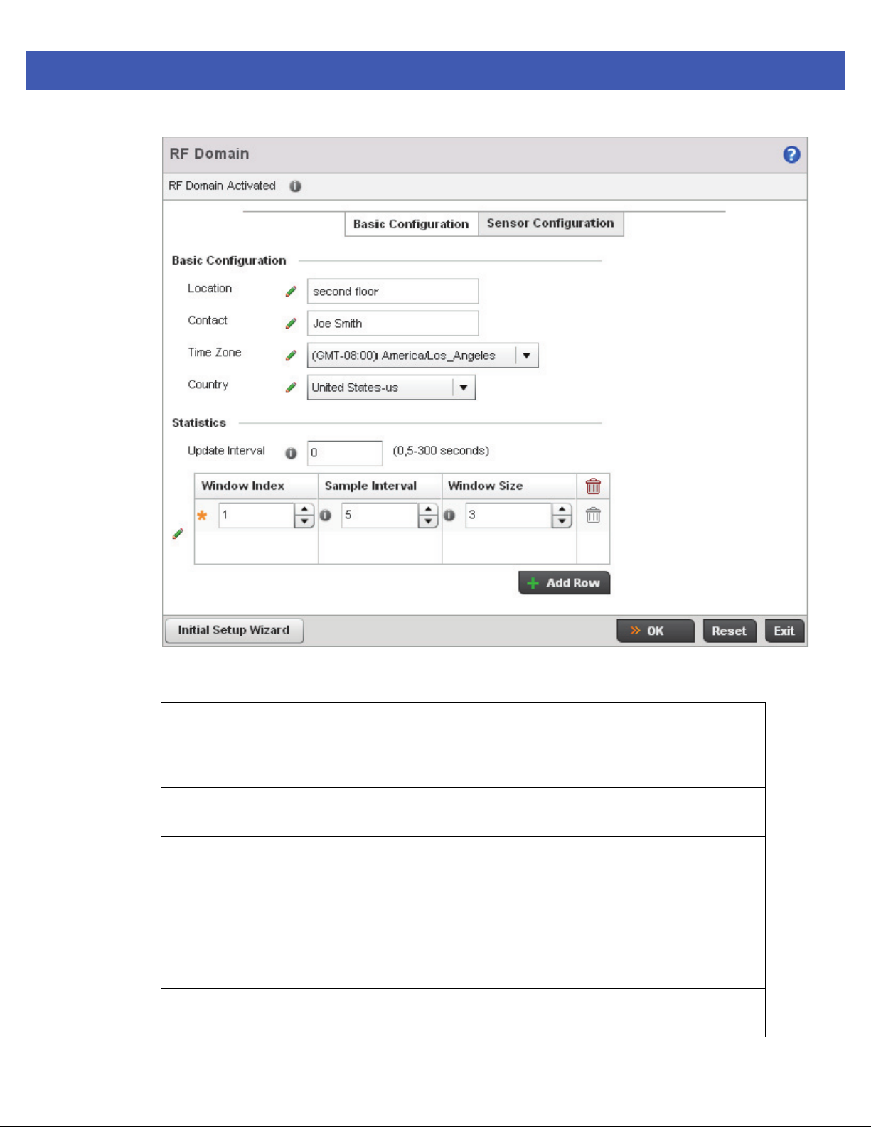
Device Configuration 5 - 3
Figure 5-1 RF Domain - Basic Configuration screen
2. Define the following Basic Configuration values for the access point RF Domain:
Location Assign the physical location of the RF Domain. This name could be as specific
as the floor of a building, or as generic as an entire site. The location defines
the physical area where a common set of access point configurations are
deployed and managed by the RF Domain policy.
Contact Provide the name of the contact email (or administrator) assigned to respond
to events created by or impacting the RF Domain.
Time Zone Set the geographic time zone for the RF Domain. The RF Domain can contain
unique country codes and time zone information to access points deployed
across different states or countries, thus making them ideal for managing
device configurations across different geographical deployments.
Country Define the two-digit country code set for the RF Domain. The country code
must be set accurately to avoid the policy’s illegal operation, as device radios
transmit in specific channels unique to the country of operation.
VLAN for Traffic
Control
Select the check box to enable a spinner control used for specifying the VLAN
(within a range of 1 - 4,094) used for traffic control within this RF Domain.
Page 64

5 - 4 WiNG 5 Access Point System Reference Guide
3. Refer to the Statistics field to define how RF Domain stats are updated:
Update Interval Set a statistics update interval of 0 or 5-3600 seconds for updates retrieved
from the access point.
Window Index Use the spinner control to set a numerical index used as an identifier for each
RF Domain statistics defined.
Sample Interval Use the spinner control to define the interval (in seconds) used by the access
point to capture windowed statistics supporting the RF Domain configuration.
The default is 5 seconds.
Window Size Use the spinner control to set the number of samples used by the controller to
define RF Domain statistics. The default value is 3.
4. Select OK to save the changes to the Basic Configuration, or select Reset to Revert to the last saved
configuration.
Page 65
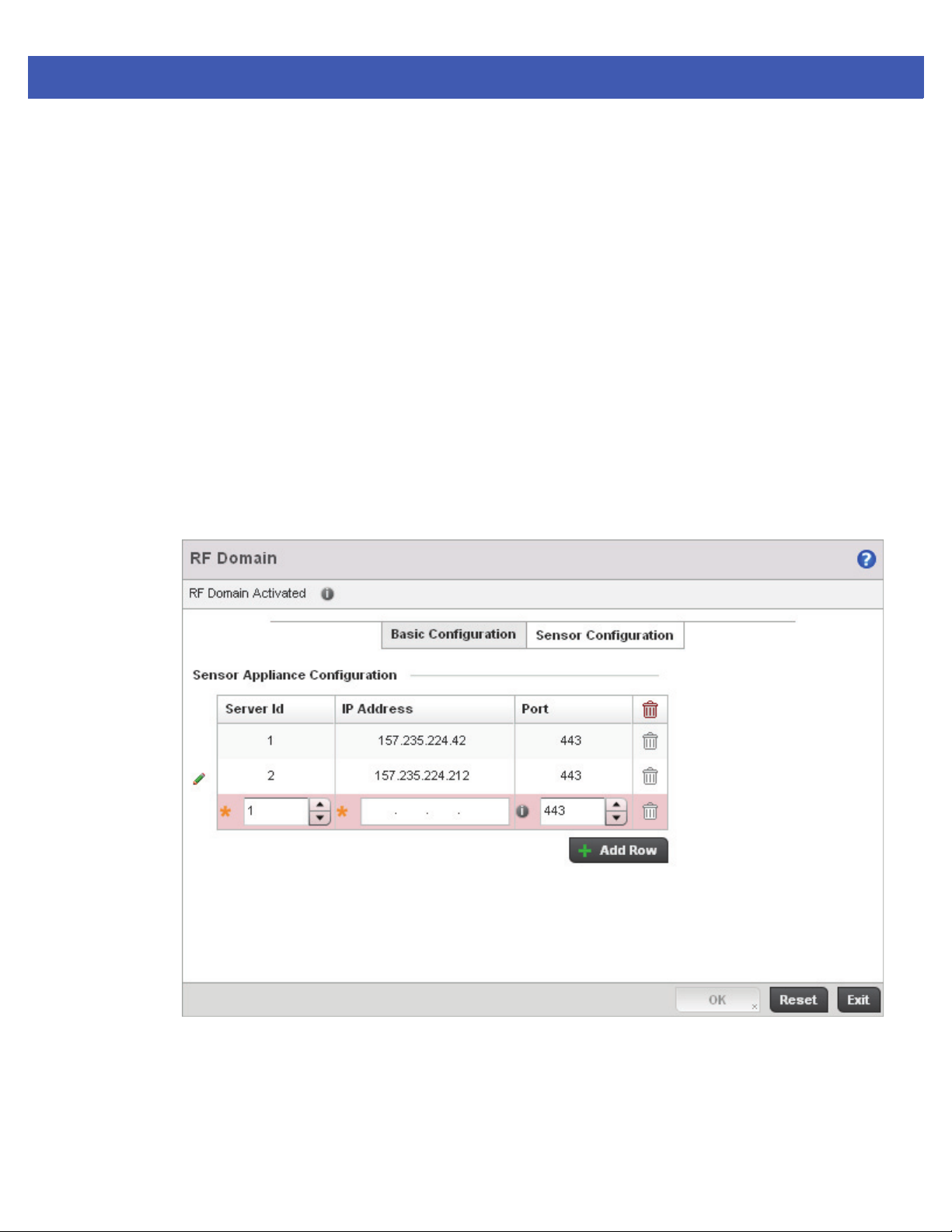
Device Configuration 5 - 5
5.2 RF Domain Sensor Configuration
The Motorola Solutions Wireless Intrusion Protection System (WIPS) protects wireless client and access point radio traffic
from attacks and unauthorized access. WIPS provides tools for standards compliance and around-the-clock wireless
network security in a distributed environment. WIPS allows administrators to identify and accurately locate attacks, rogue
devices and network vulnerabilities in real time and permits both a wired and wireless lockdown of wireless device
connections upon acknowledgement of a threat.
In addition to dedicated Motorola Solutions AirDefense sensors, an access point radio can function as a sensor and upload
information to a dedicated WIPS server (external to the access point). Unique WIPS server configurations can be used to
ensure a WIPS server configuration is available to support the unique data protection needs of a RF Domain.
WIPS is not supported on a WLAN basis, rather sensor functionality is supported on the access point radio(s) available to
each managed WLAN. When an access point radio is functioning as a WIPS sensor, it’s able to scan in sensor mode across
all legal channels within the 2.4 and 5.0 GHz band. Sensor functionality is not provided by the access point alone. The
access point works in conjunction with a dedicated WIPS server.
To define a WIPS server configuration used with the access point’s RF Domain:
1. Select Configuration > Devices > RF Domains from the Web UI.
2. Select the Sensor Configuration tab.
Figure 5-2 RF Domain - Sensor Configuration screen
3. Either select the + Add Row button to create a new WIPS server configuration or highlight an existing Sensor Server
Configuration and select the Delete icon to remove it.
4. Use the spinner control to assign a numerical Server ID to each WIPS server defined. The server with the lowest
defined ID is the first reached by the access point. The default ID is 1.
5. Provide the numerical (non DNS) IP Address of each server used as a WIPS sensor server by the RF Domain.
Page 66

5 - 6 WiNG 5 Access Point System Reference Guide
6. Use the spinner control to specify the Port of each WIPS server. The default port is 443.
7. Select OK to save the changes to the AirDefense WIPS configuration, or select Reset to Revert to the last saved
configuration.
Page 67
Device Configuration 5 - 7
5.3 System Profile Configuration
An access point profile enables an administrator to assign a common set of configuration parameters and policies to the
access point of the same model. Profiles can be used to assign common or unique network, wireless and security
parameters to across a large, multi segment, site. The configuration parameters within a profile are based on the
hardware model the profile was created to support. All WING 5 supported access point models supported a single profile
that’s either shared amongst multiple access points or not. The central benefit of a profile is its ability to update access
points collectively without having to modify individual configurations.
A profile allows access point administration across large wireless network segments. However, an administrator cannot
manage more than one model’s profile and its set configuration policies at any one time. Therefore, an administrator
should manage multiple access points directly from the Virtual Controller AP. As individual access point updates are made,
the access point no longer shares the profile based configuration it previously deployed. Changes made to the profile are
automatically inherited by all member access points, but not those who have had their configuration overridden from their
previous profile designation. These devices require careful administration, as they no longer can be tracked and as profile
members. Their customized configurations overwrite their profile assignments until the profile can be re-applied to the
access point.
Each access point model is automatically assigned a default profile. The default profile is available within the access
point’s configuration file. Default profiles are ideal for single site deployments where several access points may need to
share a common configuration.
NOTE: A central difference compared to the default-radio configurations in previous
WiNG 5 releases is that default profiles are used as pointers of an access point’s
configuration, not just templates from which the configuration is copied. Therefore, if a
change is made in one of the parameters in a profile, the change is reflected across all
access points using that profile.
For more information, refer to the following:
• General Profile Configuration
• Profile Radio Power
• Profile Adoption (Auto Provisioning) Configuration
• Profile Interface Configuration
• Profile Network Configuration
• Profile Security Configuration
• Virtual Router Redundancy Protocol (VRRP) Configuration
• Profile Critical Resources
• Profile Services Configuration
• Profile Management Configuration
• Advanced Profile Configuration
5.3.1 General Profile Configuration
An access point profile requires unique clock synchronization settings as part of its general configuration.
Network Time Protocol (NTP) manages time and/or network clock synchronization within the access point managed
network. NTP is a client/server implementation. The access point periodically synchronizes its clock with a master clock
(an NTP server). For example, the access point resets its clock to 07:04:59 upon reading a time of 07:04:59 from its
designated NTP server.
Page 68
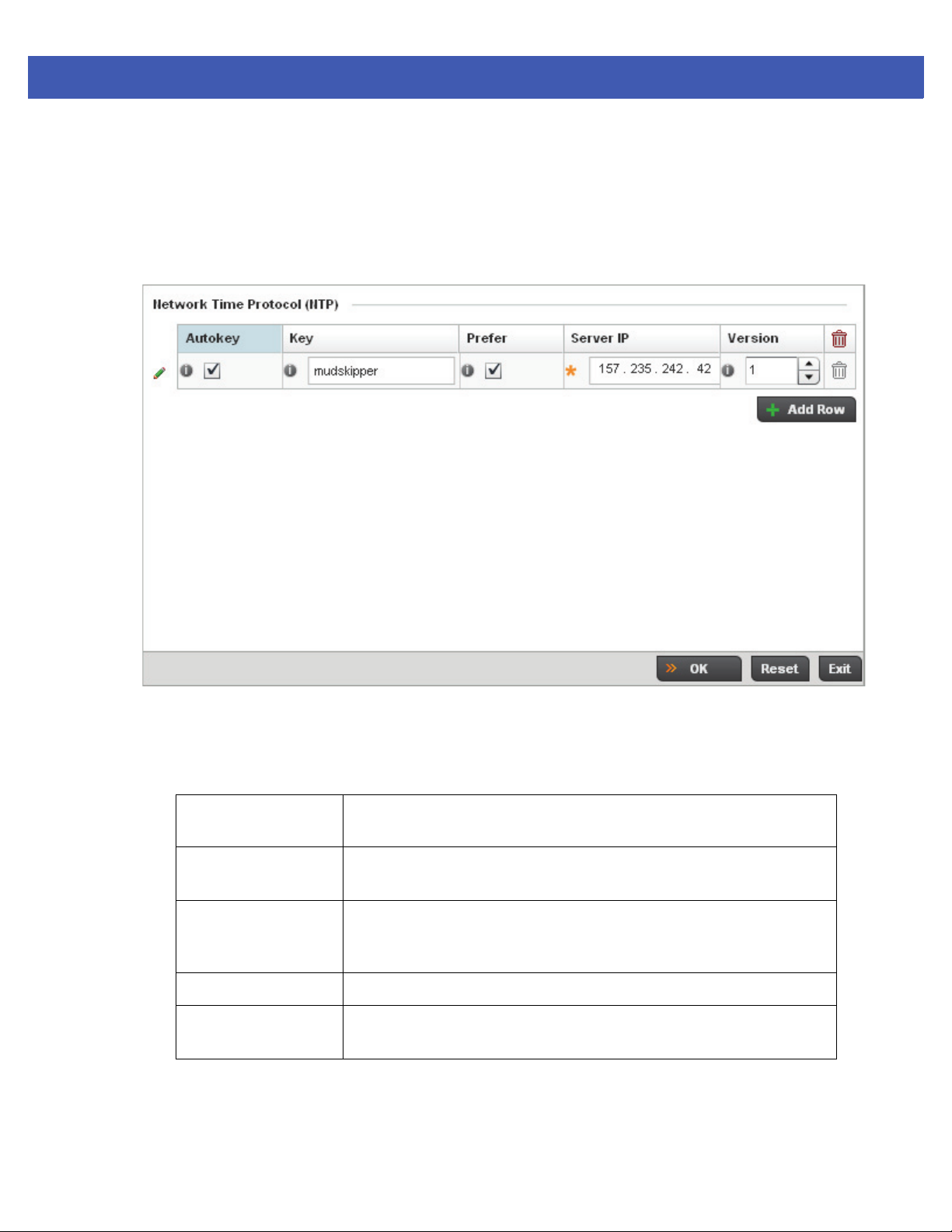
5 - 8 WiNG 5 Access Point System Reference Guide
To define a profile’s general configuration:
1. Select the Configuration tab from the Web UI.
2. Select Devices.
3. Select System Profile from the options on left-hand side of the UI.
General configuration options display by default, with the profile activated for use with this access point model.
Figure 5-3 General Profile screen
4. Select + Add Row below the Network Time Protocol (NTP) table to define the configurations of NTP server
resources the used it obtain system time by the access point’s profile. Set the following parameters to define the
NTP configuration:
AutoKey Select the radio button to enable an autokey configuration for the NTP
resource. The default setting is disabled.
Key If an autokey is not being used, manually enter a 64 character maximum key
the access point and NTP resource share to securely interoperate.
Prefer Select the radio button designate this particular NTP resource as preferred. If
designating multiple NTP resources, preferred resources will be given first
opportunity to connect and provide NTP calibration.
Server IP Set the IP address of each server added as a potential NTP resource.
Version Use the spinner control to specify the version number used by this NTP server
resource. The default setting is 0.
5. Select OK to save the changes made to the general profile configuration. Select Reset to revert to the last saved
configuration.
Page 69

5.3.2 Profile Radio Power
Use the Power screen to set one of two power modes (3af or Auto) for the access point profile. When Automatic is
selected, the access point safely operates within available power. Once the power configuration is determined, the access
point configures its operating power characteristics based on its model and power configuration.
An access point uses a complex programmable logic device (CPLD). The CPLD determines proper supply sequencing, the
maximum power available and other status information. One of the primary functions of the CPLD is to determine the
maximum power budget. When an access point is powered on (or performing a cold reset), the CPLD determines the
maximum power provided by the POE device and the budget available to the access point. The CPLD also determines the
access point hardware SKU (model) and the number of radios.
If the access point’s POE resource cannot provide sufficient power to run the access point (with all intended interfaces
enabled), some of the following interfaces could be disabled or modified:
• The access point’s transmit and receive algorithms could be negatively impacted
• The access point’s transmit power could be reduced due to insufficient power
• The access point’s WAN port configuration could be changed (either enabled or disabled)
To define an access point’s power configuration:
1. Select the Configuration tab from the Web UI.
Device Configuration 5 - 9
2. Select Devices.
3. Select System Profile from the options on left-hand side of the UI.
4. Select Power.
A screen displays where the access point profile’s power mode can be defined.
Page 70
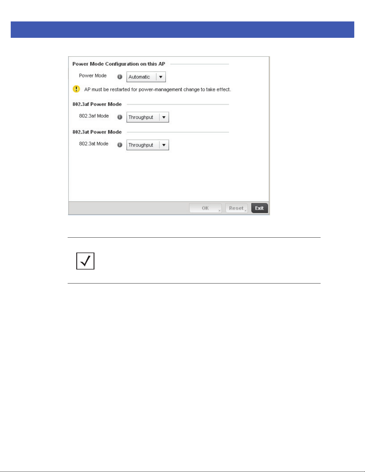
5 - 10 WiNG 5 Access Point System Reference Guide
Figure 5-4 Profile - Power screen
5. Use the Power Mode drop-down menu to set the Power Mode Configuration on this AP.
NOTE: Single radio model access point’s always operate using a full power configuration.
The power management configurations described in this section do not apply to single
radio models.
When an access point is powered on for the first time, it determines the power budget available. Using the
Automatic setting, the access point automatically determines the best power configuration based on the available
power budget. Automatic is the default setting.
If 802.3af is selected, the access point assumes 12.95 watts are available. If the mode is changed, the access
point requires a reset to implement the change. If 802.3at is selected, the access point assumes 23 - 26 watts are
available.
6. Set the Access Point radio’s 802.3af Power Mode and the radio’s 802.3at Power Mode.
Use the drop-down menu to define a mode of either Range or Throughput.
Select Throughput to transmit packets at the radio’s highest defined basic rate (based on the radio’s current basic
rate settings). This option is optimal in environments where the transmission range is secondary to
broadcast/multicast transmission performance. Select Range when range is preferred over performance for
broadcast/multicast (group) traffic. The data rates used for range are the lowest defined basic rates. Throughput
is the default setting for both 802.3af and 802.3at.
7. Select OK to save the changes made to the access point power configuration. Select Reset to revert to the last
saved configuration
Page 71
5.3.3 Profile Adoption (Auto Provisioning) Configuration
Adoption is the process an access point uses to discover Virtual Controller APs available in the network, pick the most
desirable Virtual Controller, establish an association with the and optionally obtain an image upgrade, obtains its
configuration and considers itself provisioned. This is a configurable activity that can be supported within an access point
profile and applied to other access points (of the same model) supported by the profile.
At adoption, an access point solicits and receives multiple adoption responses from Virtual Controller APs available on the
network. These adoption responses contain loading policy information the access point uses to select the optimum Virtual
Controller AP for adoption.
NOTE: An access point configuration does not need to be present for an auto
provisioning (adoption) policy to take effect. Once adopted, and the access point’s
configuration is defined and applied by the Virtual Controller, the auto provisioning policy
mapping does not have impact on subsequent adoptions by the same device.
To define the access point profile’s adoption configuration:
1. Select the Configuration tab from the Web UI.
2. Select Devices.
Device Configuration 5 - 11
3. Select System Profile from the options on left-hand side of the UI.
4. Select Adoption.
Page 72
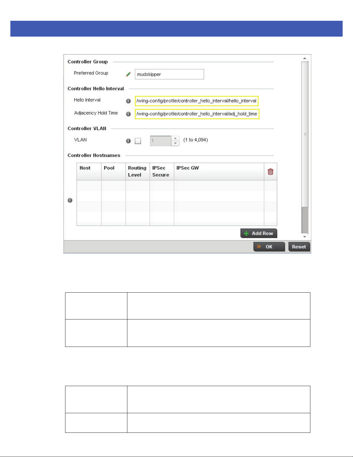
5 - 12 WiNG 5 Access Point System Reference Guide
Figure 5-5 Profile Adoption screen
5. Define the Preferred Group used as optimal group of Virtual Controller for adoption. The name of the preferred
group cannot exceed 64 characters.
6. Set the Controller Hello Interval for adopting controller discovery.
Hello Interval Define an interval between hello keep alive messages exchanged with this
access point’s adopting controller. These messages server as a connection
validation mechanism to ensure the availability of the upgrade resource.
Adjacency Hold Time Set the amount of time before the preferred group controller is considered
down and unavailable to provide upgrade services. The valid range is from 1 65,535 seconds.
7. Select the checkbox to define a VLAN the access point’s associating Virtual Controller AP is reachable on. VLANs
0 and 4,095 are reserved and cannot be used. This setting is disabled by default.
8. Enter Controller Hostnames as needed to define resources for adoption.
Host Use the drop-down menu to specify whether the controller adoption resource
is defined as a (non DNS) IP Address or a Hostname. Once defined, provide the
numerical IP or Hostname. A Hostname cannot exceed 64 characters.
Pool Use the spinner controller to set a pool of either 1 or 2. This is the pool the
target Virtual Controller belongs to. The default setting is 1.
Page 73

Device Configuration 5 - 13
Routing Level Use the spinner controller to set the routing level (either 1 or 2) for the Virtual
Controller link. The default setting is 1.
IPSec Secure Define whether a IPSec secure controller list is used in the controller adoption.
An IPSec secure link is disabled by default.
IPSec GW Specify the IP address or hostname of the adopting controller.
9. Select + Add Row as needed to populate the table with IP Addresses or Hostnames of adoption resources.
10. Select OK to save the changes made to the general profile configuration. Select Reset to revert to the last saved
configuration.
Page 74

5 - 14 WiNG 5 Access Point System Reference Guide
5.3.4 Profile Interface Configuration
A access point profile can support customizable Ethernet Port, Virtual Interface, Port Channel, Radio and PPPoE
configurations unique and to the supported AP-7131, AP-6511,AP-6532, AP-6521 or AP-7161 model.
A profile’s Interface configuration process consists of the following:
• Ethernet Port Configuration
• Virtual Interface Configuration
• Port Channel Configuration
• Access Point Radio Configuration
• PPPoE Configuration
• WAN Backhaul Configuration
Additionally, deployment considerations and guidelines for profile interface configurations are available for review
prior to defining a configuration that could significantly impact the performance of the network. For more information,
see WAN Backhaul Deployment Considerations on page 5-47.
Page 75
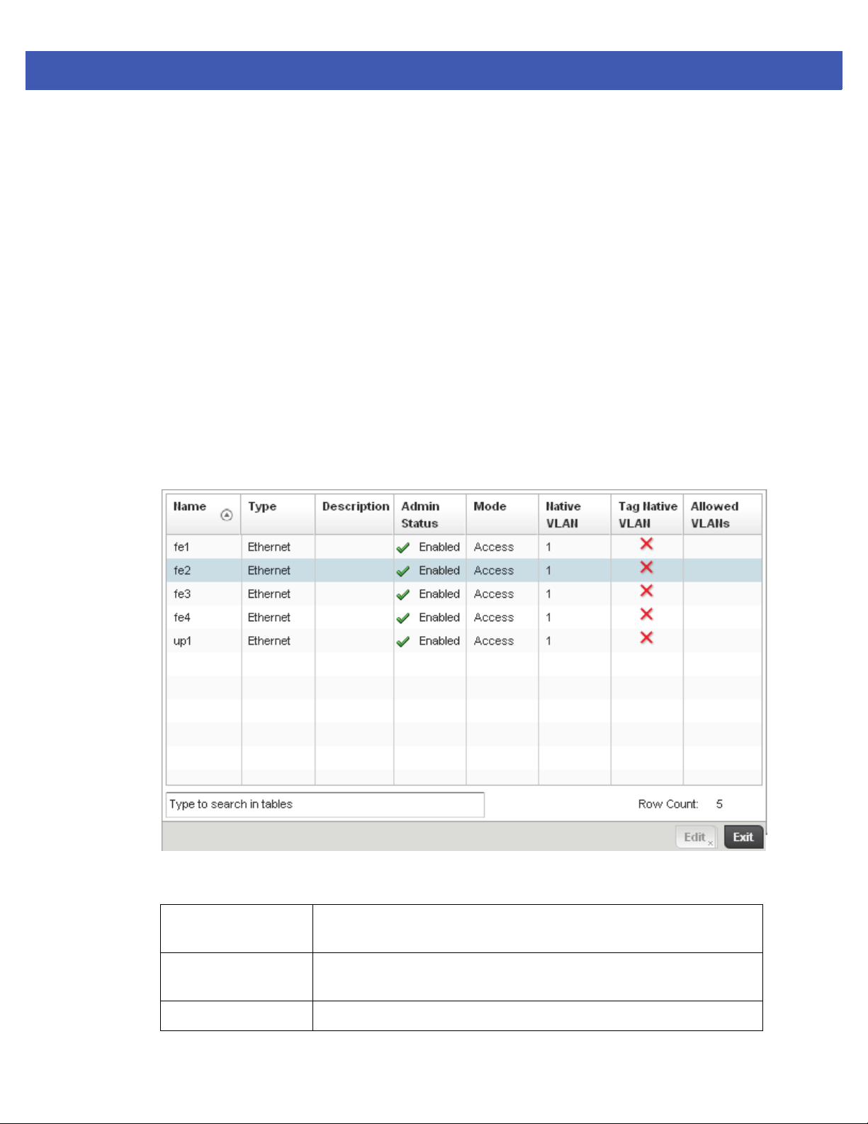
5.3.4.1 Ethernet Port Configuration
Profile Interface Configuration
Displays the physical port name reporting runtime data and statistics. The following ports are available depending on
model:
• AP-7131 - GE1/POE (LAN), GE2 (WAN)
• AP-6532 - GE1/POE (LAN)
• AP-6511 - fe1, fe2, fe3, fe4, up1
• AP-7161 - GE1/POE (LAN), GE2 (WAN)
• AP-6521 - GE1/POE (LAN)
To define a profile’s Ethernet port configuration:
1. Select the Configuration tab from the Web UI.
2. Select Devices.
3. Select System Profile from the options on left-hand side of the UI.
4. Expand the Interface menu and select Ethernet Ports.
Device Configuration 5 - 15
Figure 5-6 Profile Interfaces - Ethernet Ports screen
5. Refer to the following to assess port status, mode and VLAN configuration:
Name Displays the physical port name reporting runtime data and statistics.
Supported ports vary depending model.
Ty pe Displays the physical port type. Cooper is used on RJ45 Ethernet ports and
Optical materials are used on fiber optic gigabit Ethernet ports.
Description Displays an administrator defined description for each listed port.
Page 76

5 - 16 WiNG 5 Access Point System Reference Guide
Admin Status A green checkmark defines the port as active and currently enabled with the
profile. A red “X” defines the port as currently disabled and not available for
use. The interface status can be modified with the port configuration as
required
Mode Displays the profile’s current switching mode as either Access or Trunk. If
Access is listed, the port accepts packets only from the native VLAN. Frames
are forwarded out the port untagged with no 802.1Q header. All frames
received on the port are expected as untagged and mapped to the native VLAN.
If set to Trunk, the port allows packets from a list of VLANs added to the trunk.
A port configured as Trunk supports multiple 802.1Q tagged VLANs and one
Native VLAN which can be tagged or untagged.
Native VLAN Lists the numerical VLAN ID (1 - 4094) set for the native VLAN. The native
VLAN allows an Ethernet device to associate untagged frames to a VLAN when
no 802.1Q frame is included in the frame. Additionally, the native VLAN is the
VLAN untagged traffic is directed over when using a port in trunk mode.
Tag Native VLAN A green checkmark defines the native VLAN as tagged. A red “X” defines the
native VLAN as untagged. When a frame is tagged, the 12 bit frame VLAN ID
is added to the 802.1Q header so upstream Ethernet devices know which VLAN
ID the frame belongs to. The device reads the 12 bit VLAN ID and forwards the
frame to the appropriate VLAN. When a frame is received with no 802.1Q
header, the upstream device classifies the frame using the default or native
VLAN assigned to the Trunk port. A native VLAN allows an Ethernet device to
associate untagged frames to a VLAN when no 802.1Q frame is included in the
frame.
Allowed VLANs Displays the VLANs allowed to send packets over the listed port. Allowed
VLANs are only listed when the mode has been set to Trunk.
6. To edit an access point profile’s port configuration, select it from amongst those displayed and select the Edit
button. The Ethernet port Basic Configuration screen displays by default.
Page 77
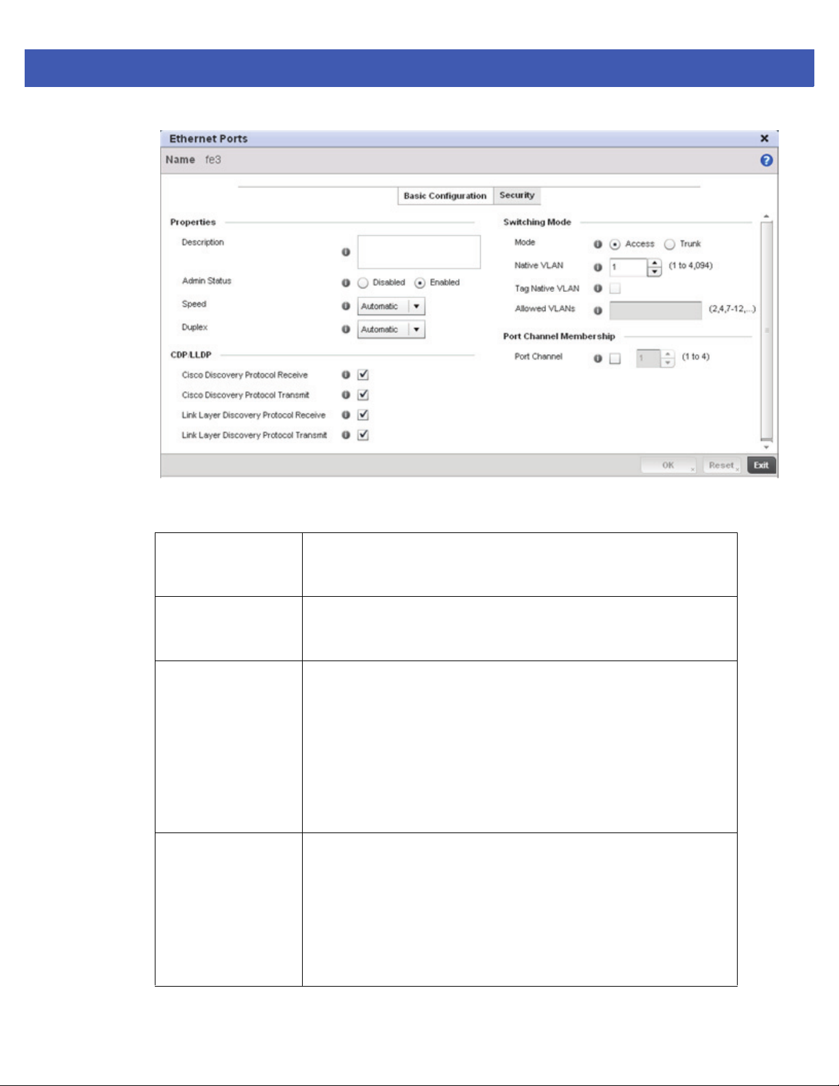
Device Configuration 5 - 17
Figure 5-7 Ethernet Ports - Basic Configuration screen
7. Set the following Ethernet port Properties:
Description Enter a brief description for the port (64 characters maximum). The description
should reflect the port’s intended function to differentiate it from others with
similar configurations.
Admin Status Select the Enabled radio button to define this port as active to the profile it
supports. Select the Disabled radio button to disable this physical port in the
profile. It can be activated at any future time when needed.
Speed Select the speed at which the port can receive and transmit the data. Select
either 10 Mbps, 100 Mbps, 1000 Mbps. Select either of these options to
establish a 10, 100 or 1000 Mbps data transfer rate for the selected half duplex
or full duplex transmission over the port. These options are not available if
Auto is selected. Select Automatic to enable the port to automatically
exchange information about data transmission speed and duplex capabilities.
Auto negotiation is helpful when in an environment where different devices
are connected and disconnected on a regular basis. Automatic is the default
setting.
Duplex Select either half, full or automatic as the duplex option. Select Half duplex to
send data over the port, then immediately receive data from the same direction
in which the data was transmitted. Like a full-duplex transmission, a
half-duplex transmission can carry data in both directions, just not at the same
time. Select Full duplex to transmit data to and from the port at the same time.
Using full duplex, the port can send data while receiving data as well. Select
Automatic to enable to the access point to dynamically duplex as port
performance needs dictate. Automatic is the default setting.
Page 78

5 - 18 WiNG 5 Access Point System Reference Guide
8. Define the following Cisco Discovery Protocol (CDP) and LLDP parameters to apply to the Ethernet port
configuration.
Cisco Discover
Protocol Receive
Cisco Discover
Protocol Transmit
Link Layer Discovery
Protocol Receive
Link Layer Discovery
Protocol Transmit
9. Define the following Switching Mode parameters to apply to the Ethernet port configuration:
Mode Select either the Access or Trunk radio button to set the VLAN switching mode
Native VLAN Use the spinner control to define a numerical Native VLAN ID between 1 -
Select the radio button to allow the Cisco discovery protocol for receiving data
on this port.
Select the radio button to allow the Cisco discovery protocol for transmitting
data on this port.
Select this option to snoop LLDP on this port. The default setting is enabled.
Select this option to transmit LLDP PDUs on this port. The default setting is
disabled.
over the port. If Access is selected, the port accepts packets only form the
native VLANs. Frames are forwarded out the port untagged with no 802.1Q
header. All frames received on the port are expected as untagged and are
mapped to the native VLAN. If the mode is set to Trunk, the port allows packets
from a list of VLANs you add to the trunk. A port configured as Trunk supports
multiple 802.1Q tagged VLANs and one Native VLAN which can be tagged or
untagged. Access is the default mode.
4094. The native VLAN allows the access point to associate untagged frames
to a VLAN when no 802.1Q frame is included in the frame. Additionally, the
native VLAN is the VLAN which untagged traffic will be directed over when
using a port in trunk mode. The default VLAN is 1.
Tag Native VLAN Select the radio button to tag the native VLAN. The IEEE 802.1Q specification
is supported for tagging frames and coordinating VLANs between devices.
IEEE 802.1Q adds four bytes to each frame identifying the VLAN ID for
upstream devices that the frame belongs. If the upstream Ethernet device does
not support IEEE 802.1Q tagging, it does not interpret the tagged frames. When
VLAN tagging is required between devices, both devices must support tagging
and be configured to accept tagged VLANs. When a frame is tagged, the 12 bit
frame VLAN ID is added to the 802.1Q header so upstream Ethernet devices
know which VLAN ID the frame belongs to. The device reads the 12 bit VLAN
ID and forwards the frame to the appropriate VLAN. When a frame is received
with no 802.1Q header, the upstream device classifies the frame using the
default or native VLAN assigned to the Trunk port. The native VLAN allows an
Ethernet device to associate untagged frames to a VLAN when no 802.1Q
frame is included in the frame. This feature is disabled by default.
Allowed VLANs Selecting Trunk as the mode enables the Allowed VLANs parameter. Add
VLANs that exclusively send packets over the listed port.
10. Optionally select the Port Channel checkbox and define a setting between 1 - 8 using the spinner control. This
sets the channel group for the port.
Page 79
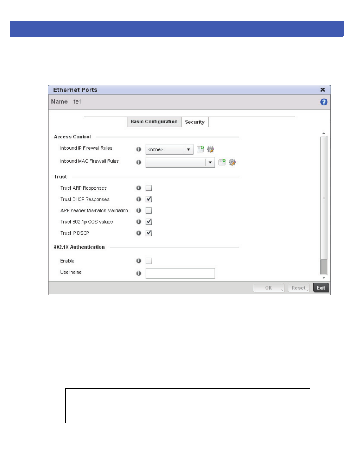
Device Configuration 5 - 19
11. Select OK to save the changes made to the Ethernet Port Basic Configuration. Select Reset to revert to the last saved
configuration.
12. Select the Security tab.
Figure 5-8 Ethernet Ports - Security screen
13. Refer to the Access Control field. As part of the port’s security configuration, Inbound IP and MAC address firewall
rules are required.
Use the Inbound IP Firewall Rules and Inbound MAC Firewall Rules drop-down menus to select the firewall rules to
apply to this profile’s Ethernet port configuration.
The firewall inspects IP and MAC traffic flows and detects attacks typically not visible to traditional wired firewall
appliances.
14. If a firewall rule does not exist suiting the data protection needs of the target port configuration, select the Create
icon to define a new rule configuration.
15. Refer to the Trus t field to define the following:
Trust ARP Responses Select the radio button to enable ARP trust on this access point port. ARP
packets received on this port are considered trusted and information from
these packets is used to identify rogue devices within the network. The
default value is disabled.
Page 80
5 - 20 WiNG 5 Access Point System Reference Guide
Trust DHCP Responses Select the radio button to enable DHCP trust on this port. If enabled, only
DHCP responses are trusted and forwarded on this port, and a DHCP server
can be connected only to a DHCP trusted port. The default value is enabled.
ARP header Mismatch
Validation
Trust 8021p COS values Select the radio button to enable 802.1p COS values on this port. The default
Trust IP DSCP Select the radio button to enable IP DSCP values on this port. The default
NOTE: Some vendor solutions with VRRP enabled send ARP packets with Ethernet SMAC
as a physical MAC and inner ARP SMAC as VRRP MAC. If this configuration is enabled, a
packet is allowed, despite a conflict existing.
16. Select the Enable checkbox within the 802.1x Authentication field to enable a username and password pair to
be used when authenticating users on this port.
17. Select OK to save the changes made to the Ethernet port’s security configuration. Select Reset to revert to the
last saved configuration.
Select the radio button to enable a mismatch check for the source MAC in
both the ARP and Ethernet header. The default value is disabled.
value is enabled.
value is enabled.
Page 81
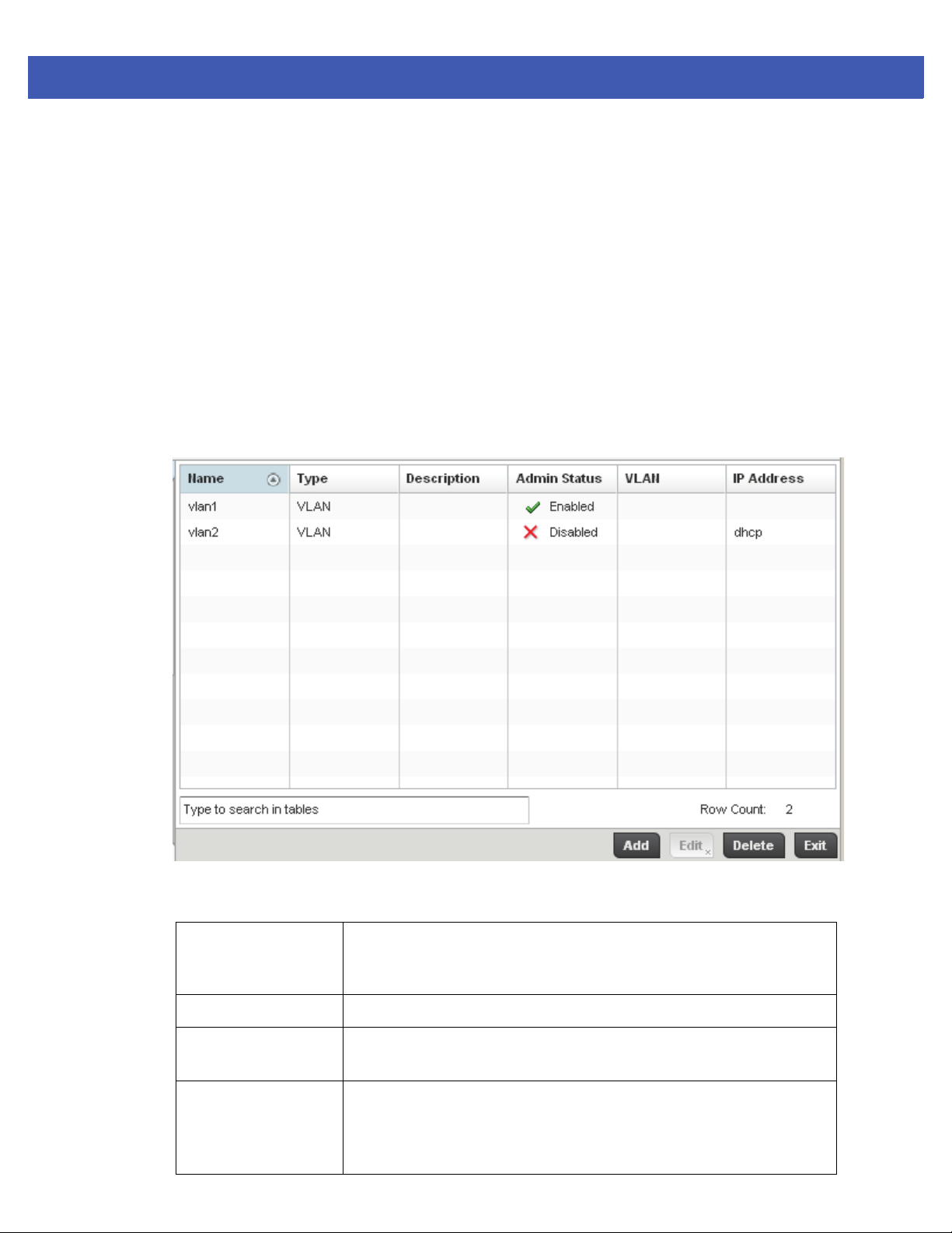
5.3.4.2 Virtual Interface Configuration
Profile Interface Configuration
A Virtual Interface is required for layer 3 (IP) access to provide layer 3 service on a VLAN. The Virtual Interface defines
which IP address is associated with each VLAN ID the access point is connected to. A Virtual Interface is created for the
default VLAN (VLAN 1) to enable remote administration. A Virtual Interface is also used to map VLANs to IP address
ranges. This mapping determines the destination networks for routing.
To review existing Virtual Interface configurations and either create a new Virtual Interface configuration, modify an
existing configuration or delete an existing configuration:
1. Select the Configuration tab from the Web UI.
2. Select Devices.
3. Select System Profile from the options on left-hand side of the UI.
4. Expand the Interface menu and select Virtual Interfaces.
Device Configuration 5 - 21
Figure 5-9 Profile Interfaces - Virtual Interfaces screen
Review the following parameters unique to each virtual interface configuration:
Name Displays the name of each listed Virtual Interface assigned when it was
created. The name is between 1 - 4094, and cannot be modified as part of a
Virtual Interface edit.
Ty pe Displays the type of Virtual Interface for each listed access point interface.
Description Displays the description defined for the Virtual Interface when it was either
initially created or edited.
Admin Status A green checkmark defines the listed Virtual Interface configuration as active
and enabled with its supported profile. A red “X” defines the Virtual Interface
as currently disabled. The interface status can be modified when a new Virtual
Interface is created or an existing one modified.
Page 82
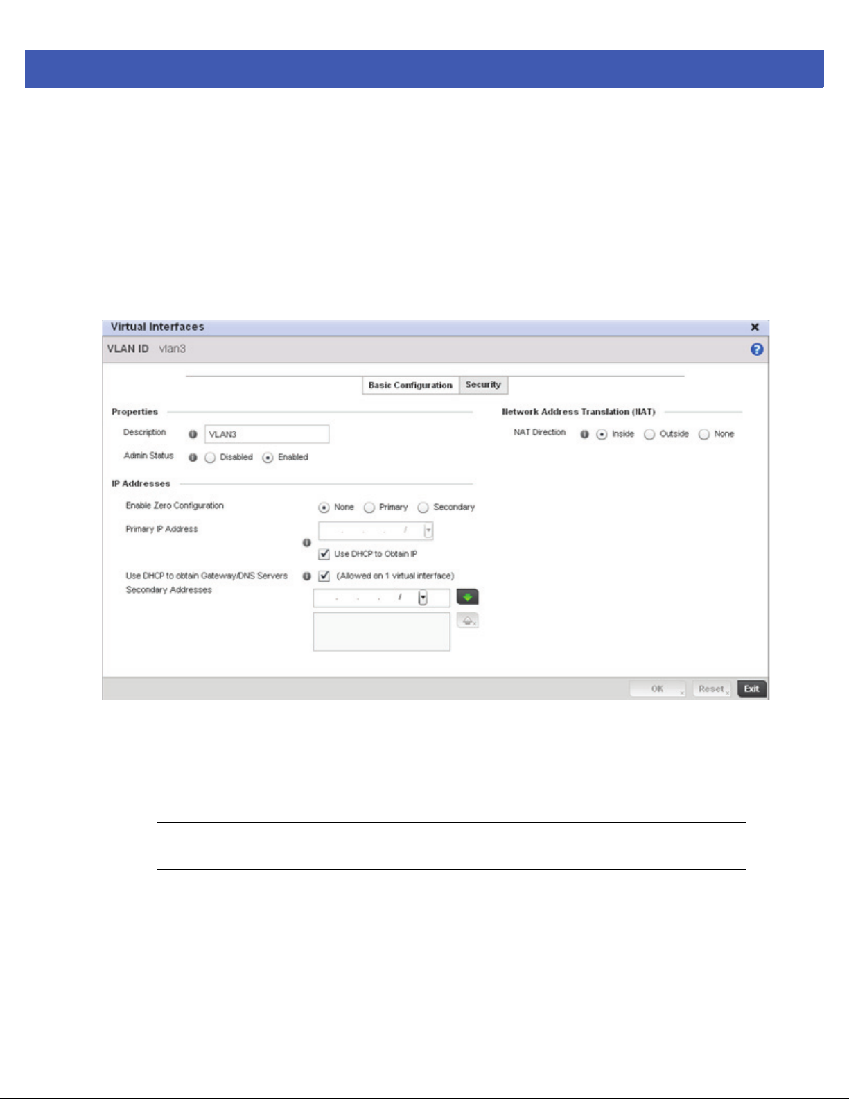
5 - 22 WiNG 5 Access Point System Reference Guide
VLAN Displays the numerical VLAN ID associated with each listed interface.
IP Address Defines whether DHCP was used to obtain the primary IP address used by the
Virtual Interface configuration.
Once the configurations of existing Virtual Interfaces have been reviewed, determine whether a new interface
requires creation, or an existing Virtual Interface requires edit or deletion.
5. Select Add to define a new Virtual Interface configuration, Edit to modify the configuration of an existing Virtual
Interface or Delete to permanently remove a selected Virtual Interface.
Figure 5-10 Virtual Interfaces - Basic Configuration screen
The Basic Configuration screen displays by default regardless of a whether a new Virtual Interface is being
created or an existing one is being modified.
6. If creating a new Virtual Interface, use the Name spinner control to define a numeric ID between 1 - 4094.
7. Define the following parameters from within the Properties field:
Description Provide or edit a description (up to 64 characters) for the Virtual Interface that
helps differentiate it from others with similar configurations.
Admin Status Either select the Disabled or Enabled radio button to define this interface’s
current status within the network. When set to Enabled, the Virtual Interface
is operational and available. The default value is disabled.
Page 83

8. Set the following network information from within the IP Addresses field:
Device Configuration 5 - 23
Enable Zero
Configuration
Primary IP Address Define the IP address for the VLAN associated Virtual Interface.
Use DHCP to Obtain IP Select this option to allow DHCP to provide the IP address for the Virtual
Use DHCP to obtain
Gateway/DNS
Servers
Secondary Addresses Use the Secondary Addresses parameter to define additional IP addresses to
9. Define the Network Address Translation (NAT) direction.
Select either the Inside, Outside or None radio buttons.
• Inside - The inside network is transmitting data over the network its intended destination. On the way out, the
source IP address is changed in the header and replaced by the (public) IP address.
The access point can use Zero Config for IP assignments on an individual
virtual interface basis. Select Primary to use Zero Config as the designated
means of providing an IP address, this eliminates the means to assign one
manually. Selecting Secondary is preferred when wanting the option to either
use Zero Config or manual assignments.
Interface. Selecting this option disables the Primary IP address field.
Select this option to allow DHCP to obtain a default gateway address, and DNS
resource for one virtual interface. This setting is disabled by default and only
available when the Use DHCP to Obtain IP option is selected.
associate with VLAN IDs. The address provided in this field is used if the
primary IP address is unreachable.
• Outside - Packets passing through the NAT on the way back to the LAN are searched against to the records kept by
the NAT engine. There the destination IP address is changed back to the specific internal private class IP address
in order to reach the LAN over the network.
• None - No NAT activity takes place. This is the default setting.
10. Select OK button to save the changes to the Basic Configuration screen. Select Reset to revert to the last saved
configuration.
11. Select the Security tab.
Page 84
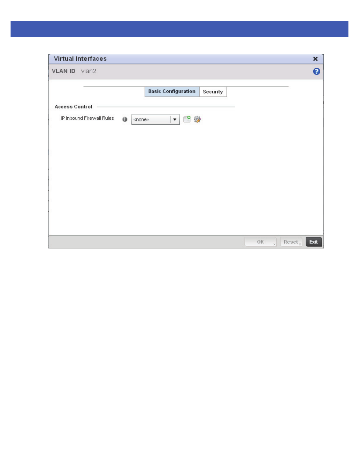
5 - 24 WiNG 5 Access Point System Reference Guide
Figure 5-11 Virtual Interfaces - Security screen
12. Use the Inbound IP Firewall Rules drop-down menu to select the firewall rule configuration to apply to this
Virtual Interface.
The firewall inspects and packet traffic to and from connected clients.
If a firewall rule does not exist suiting the data protection needs of this Virtual Interface, select the Create icon
to define a new firewall rule configuration or the Edit icon to modify an existing configuration. For more
information, see Wireless Firewall on page 8-2.
13. Select the OK button located at the bottom right of the screen to save the changes to the Security screen. Select
Reset to revert to the last saved configuration.
Page 85
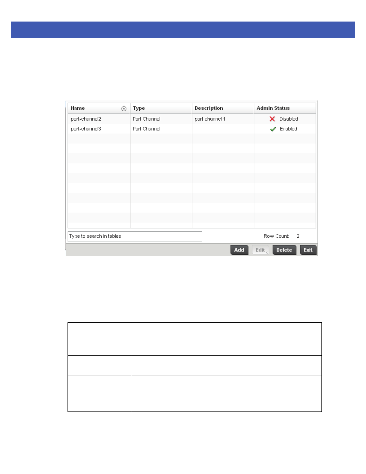
5.3.4.3 Port Channel Configuration
Profile Interface Configuration
The access point’s profile can be applied customized port channel configurations as part of its Interface configuration.
To define a port channel configuration for a controller profile:
Device Configuration 5 - 25
Figure 5-12 Profile Interfaces - Port Channels screen
1. Select the Configuration tab from the Web UI.
2. Select Devices.
3. Select System Profile from the options on left-hand side of the UI.
4. Expand the Interface menu and select Port Channels.
5. Refer to the following to review existing port channel configurations and their current status:
Name Displays the port channel’s numerical identifier assigned to it when it was
created. The numerical name cannot be modified as part of the edit process.
Ty pe Displays whether the type is port channel.
Description Lists a a short description (64 characters maximum) describing the port channel
or differentiating it from others with similar configurations.
Admin Status A green checkmark defines the listed port channel as active and currently
enabled with the access point’s profile. A red “X” defines the port channel as
currently disabled and not available for use. The interface status can be
modified with the port channel configuration as required
6. To edit the configuration of an existing port channel, select it from amongst those displayed and select the Edit button.
The port channel Basic Configuration screen displays by default.
Page 86
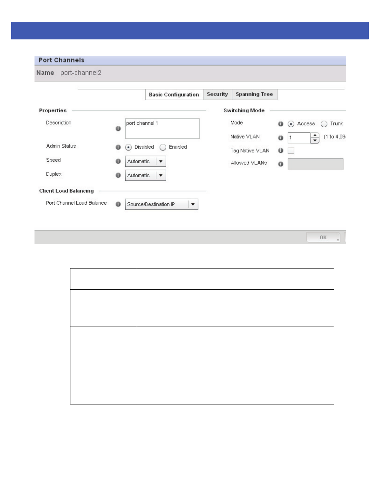
5 - 26 WiNG 5 Access Point System Reference Guide
Figure 5-13 Port Channels - Basic Configuration screen
7. Set the following port channel Properties:
Description Enter a brief description for the port channel (64 characters maximum). The
description should reflect the port channel’s intended function.
Admin Status Select the Enabled radio button to define this port channel as active to the
controller profile it supports. Select the Disabled radio button to disable this
port channel configuration within the profile. It can be activated at any future
time when needed. The default setting is disabled.
Speed Select the speed at which the port channel can receive and transmit the data.
Select either 10 Mbps, 100 Mbps, 1000 Mbps. Select either of these options
to establish a 10, 100 or 1000 Mbps data transfer rate for the selected half
duplex or full duplex transmission over the port. These options are not
available if Auto is selected. Select Automatic to enable the port channel to
automatically exchange information about data transmission speed and duplex
capabilities. Auto negotiation is helpful when in an environment where
different devices are connected and disconnected on a regular basis.
Automatic is the default setting.
Page 87

Device Configuration 5 - 27
Duplex Select either Half, Full or Automatic as the duplex option. Select Half duplex
to send data over the port channel, then immediately receive data from the
same direction in which the data was transmitted. Like a Full duplex
transmission, a Half duplex transmission can carry data in both directions, just
not at the same time. Select Full duplex to transmit data to and from the port
channel at the same time. Using Full duplex, the port channel can send data
while receiving data as well. Select Automatic to enable to the access point to
dynamically duplex as port channel performance needs dictate. Automatic is
the default setting.
8. Use the Port Channel Load Balance drop-down menu to define whether port channel load balancing is conducted
using a Source/Destination IP or a Source/Destination MAC as criteria. Source/Destination IP is the default setting.
9. Define the following Switching Mode parameters to apply to the port channel configuration:
Mode Select either the Access or Tr un k radio button to set the VLAN switching mode
over the port channel. If Access is selected, the port channel accepts packets
only form the native VLANs. Frames are forwarded out the port untagged with
no 802.1Q header. All frames received on the port are expected as untagged
and are mapped to the native VLAN. If the mode is set to Trunk, the port
channel allows packets from a list of VLANs you add to the trunk. A port
channel configured as Trunk supports multiple 802.1Q tagged VLANs and one
Native VLAN which can be tagged or untagged. Access is the default setting.
Native VLAN Use the spinner control to define a numerical ID between 1 - 4094. The native
VLAN allows an Ethernet device to associate untagged frames to a VLAN when
no 802.1Q frame is included in the frame. Additionally, the native VLAN is the
VLAN which untagged traffic will be directed over when using trunk mode. The
default value is 1.
Tag the Native
VLAN
Allowed VLANs Selecting Tr un k as the mode enables the Allowed VLANs parameter. Add
Select the checkbox to tag the native VLAN. Access points support the IEEE
802.1Q specification for tagging frames and coordinating VLANs between
devices. IEEE 802.1Q adds four bytes to each frame identifying the VLAN ID for
upstream devices that the frame belongs. If the upstream Ethernet device does
not support IEEE 802.1Q tagging, it does not interpret the tagged frames. When
VLAN tagging is required between devices, both devices must support tagging
and be configured to accept tagged VLANs. When a frame is tagged, the 12 bit
frame VLAN ID is added to the 802.1Q header so upstream Ethernet devices
know which VLAN ID the frame belongs to. The device reads the 12 bit VLAN
ID and forwards the frame to the appropriate VLAN. When a frame is received
with no 802.1Q header, the upstream device classifies the frame using the
default or native VLAN assigned to the Trunk port. The native VLAN allows an
Ethernet device to associate untagged frames to a VLAN when no 802.1Q
frame is included in the frame. This setting is disabled by default.
VLANs that exclusively send packets over the port channel.
10. Select OK to save the changes made to the port channel Basic Configuration. Select Reset to revert to the last saved
configuration.
11. Select the Security tab.
Page 88
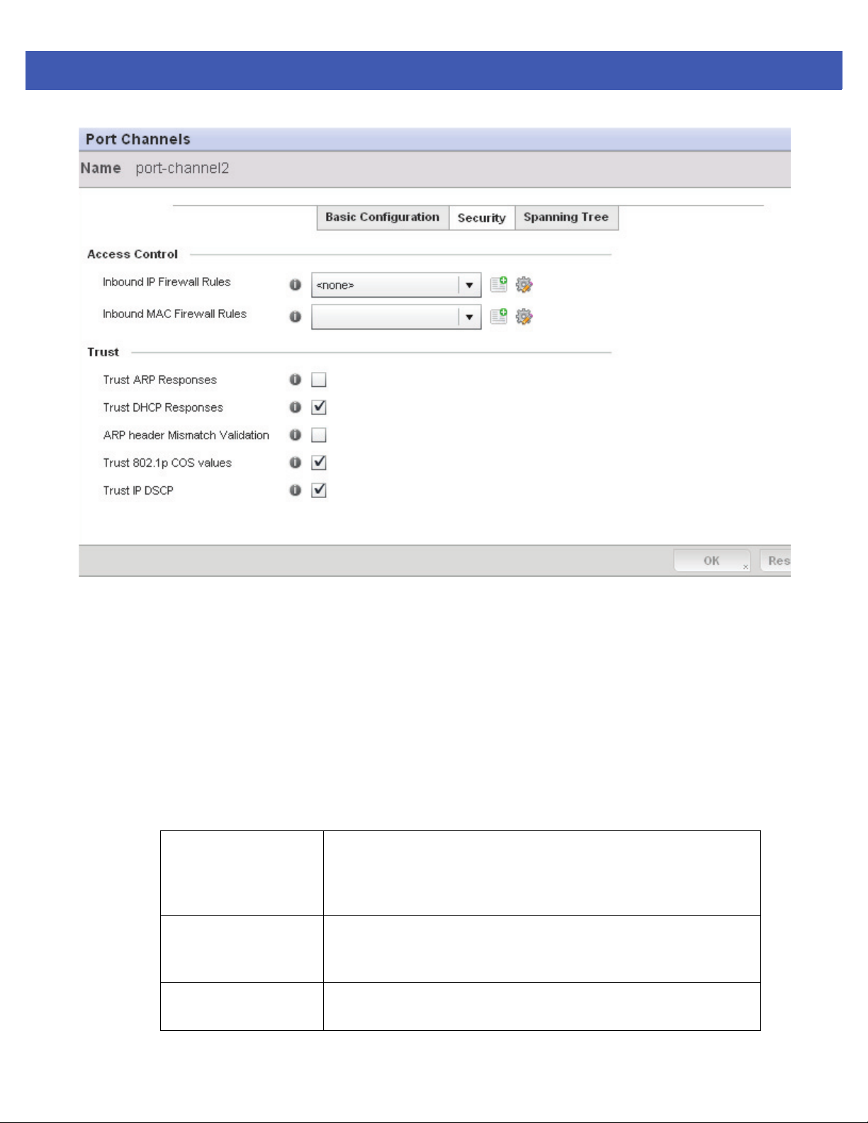
5 - 28 WiNG 5 Access Point System Reference Guide
Figure 5-14 Port Channels - Security screen
12. Refer to the Access Control field. As part of the port channel’s security configuration, Inbound IP and MAC
address firewall rules are required.
Use the Inbound IP Firewall Rules and Inbound MAC Firewall Rules drop-down menus to select firewall rules to
apply to this profile’s port channel configuration.
The firewall inspects IP and MAC traffic flows and detects attacks typically not visible to traditional wired firewall
appliances.
If a firewall rule does not exist suiting the data protection needs of the target port channel configuration, select
the Create icon to define a new rule configuration or the Edit icon to modify an existing firewall rule configuration.
For more information, see Wireless Firewall on page 8-2.
13. Refer to the Tru st field to define the following:
Trust ARP Responses Select the check box to enable ARP trust on this port channel. ARP packets
received on this port are considered trusted and information from these
packets is used to identify rogue devices within the managed network. The
default value is disabled.
Trust DHCP Responses Select the check box to enable DHCP trust. If enabled, only DHCP responses
are trusted and forwarded on this port channel, and a DHCP server can be
connected only to a DHCP trusted port. The default value is enabled.
ARP header Mismatch
Validation
Select the check box to enable a mismatch check for the source MAC in both
the ARP and Ethernet header. The default value is enabled.
Page 89
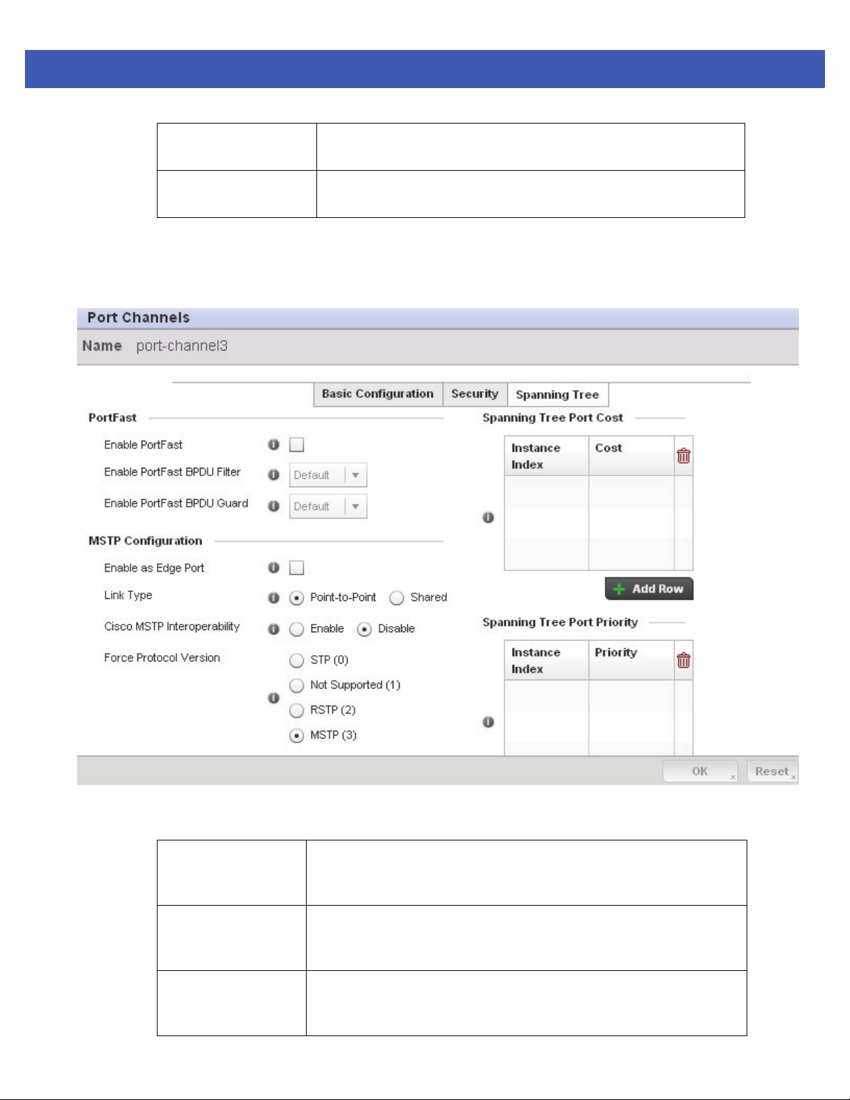
Device Configuration 5 - 29
Trust 802.1p COS values Select the check box to enable 802.1p COS values on this port channel. The
default value is enabled.
Trust IP DSCP Select the check box to enable IP DSCP values on this port channel. The
default value is disabled.
14. Select OK to save the changes to the security configuration. Select Reset to revert to the last saved configuration.
15. Select the Spanning Tree tab.
Figure 5-15 Port Channels - Spanning Tree screen
16. Define the following PortFast parameters for the port channel’s MSTP configuration:
Enable PortFast Select the check box to enable drop-down menus for both the Enable Portfast
BPDU Filter and Enable Portfast BPDU Guard options. This setting is disabled
by default.
PortFast BPDU Filter Select Enable to invoke a BPDU filter for this portfast enabled port channel.
Enabling the BPDU filter feature ensures this port channel does not transmit or
receive any BPDUs. The default setting is None.
PortFast BPDU Guard Select Enable to invoke a BPDU guard for this portfast enabled port channel.
Enabling the BPDU Guard feature means this port will shutdown on receiving
a BPDU. Thus, no BPDUs are processed. The default setting is None.
Page 90

5 - 30 WiNG 5 Access Point System Reference Guide
17. Set the following MSTP Configuration parameters for the port channel:
Enable as Edge Port Select the check box to define this port as an edge port. Using an edge
(private) port, you can isolate devices to prevent connectivity over this port
channel. This setting is disabled by default.
Link Type Select either the Point-to-Point or Shared radio button. Selecting
Point-to-Point indicates the port should be treated as connected to a
point-to-point link. Selecting Shared means this port should be treated as
having a shared connection. A port connected to a hub is on a shared link,
while one connected to a access point is a point-to-point link. Point-to-Point
is the default setting.
Cisco MSTP
Interoperability
Force Protocol Version Sets the protocol version to either STP(0), Not Supported(1), RSTP(2) or
Guard Determines whether the port channel enforces root bridge placement.
18. Refer to the Spanning Tree Port Cost table.
Define an Instance Index using the spinner control and then set the cost. The default path cost depends on the
user defined port speed.The cost helps determine the role of the port channel in the MSTP network. The
designated cost is the cost for a packet to travel from this port to the root in the MSTP configuration. The slower
the media, the higher the cost.
Speed Default Path Cost
Select either the Enable or Disable radio buttons. This enables
interoperability with Cisco’s version of MSTP, which is incompatible with
standard MSTP. This setting is disabled by default.
MSTP(3). MSTP is the default setting.
Setting the guard to Root ensures the port is a designated port. Typically,
each guard root port is a designated port, unless two or more ports (within
the root bridge) are connected together. If the bridge receives superior
(BPDUs) on a guard root-enabled port, the guard root moves the port to a
root-inconsistent STP state. This state is equivalent to a listening state. No
data is forwarded across the port. Thus, the guard root enforces the root
bridge position.
<=100000 bits/sec 200000000
<=1000000 bits/sec 20000000
<=10000000 bits/sec 2000000
<=100000000 bits/sec 200000
<=1000000000 bits/sec 20000
<=10000000000 bits/sec 2000
<=100000000000 bits/sec 200
<=1000000000000 bits/sec 20
>1000000000000 bits/sec 2
Page 91

Device Configuration 5 - 31
19. Select + Add Row as needed to include additional indexes.
20. Refer to the Spanning Tree Port Priority table.
Define an Instance Index using the spinner control and then set the Priority. The lower the priority, a greater likelihood
of the port becoming a designated port.
Select + Add Row needed to include additional indexes.
21. Select OK to save the changes made to the Ethernet Port Spanning Tree configuration. Select Reset to revert to the
last saved configuration.
Page 92
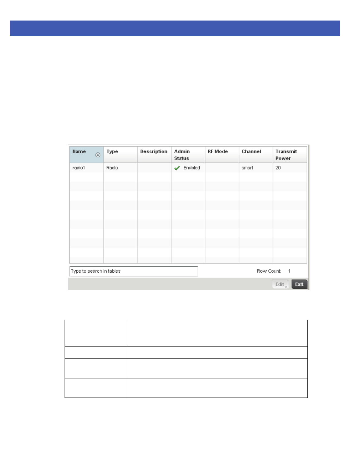
5 - 32 WiNG 5 Access Point System Reference Guide
5.3.4.4 Access Point Radio Configuration
Profile Interface Configuration
An access point profile can have its radio configuration modified once its radios have successfully associated to the
network.
To define a Access Point radio configuration:
1. Select the Configuration tab from the Web UI.
2. Select Devices.
3. Select System Profile from the options on left-hand side of the UI.
4. Expand the Interface menu and select Radios.
Figure 5-16 Access Point Radios screen
5. Review the following radio configuration data to determine whether a radio configuration requires modification
to better support the network:
Name Displays whether the reporting radio is radio 1, radio 2 or radio 3. AP-7131
models can have up to 3 radios depending on the SKU. AP-6532 and AP-7161
models have 2 radios, while AP-6511 and AP-6521 models have 1 radio.
Ty pe Displays the type of radio housed by each listed access point.
Description Displays a brief description of the radio provided by the administrator when the
radio’s configuration was added or modified.
Admin Status A red “X” defines the radio’s admin status as currently disabled. A green
checkmark designates the admin status as enabled.
Page 93
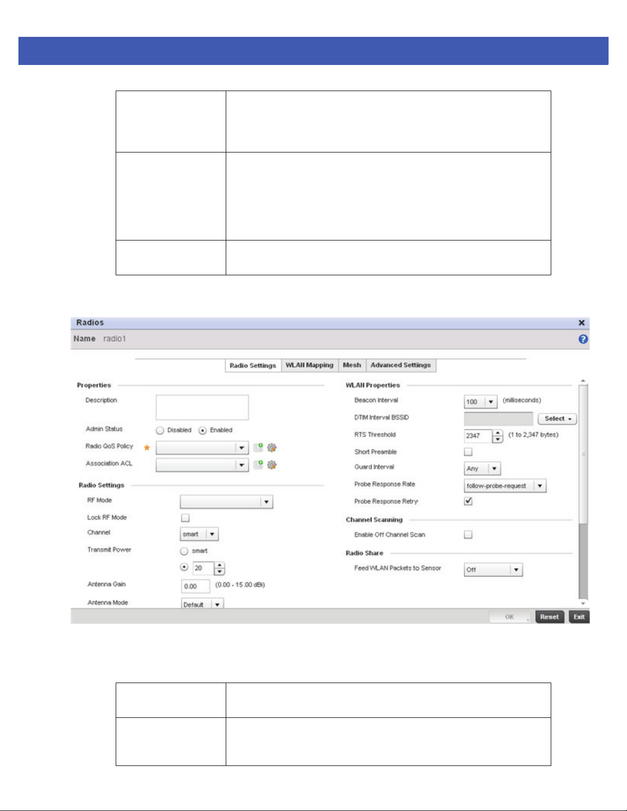
Device Configuration 5 - 33
RF Mode Displays whether each listed radio is operating in the 802.11a/n or
802.11b/g/n radio band. If the radio is a dedicated sensor, it will be listed as a
sensor to define the radio as not providing typical WLAN support. The radio
band is set from within the Radio Settings tab.
Channel Lists the channel setting for the radio. Smart is the default setting. If set to
smart, the access point scans non-overlapping channels listening for beacons
from other access points. After the channels are scanned, it selects the
channel with the fewest access points. In the case of multiple access points
on the same channel, it will select the channel with the lowest average power
level.
Transmit Power Lists the transmit power for each radio. The column displays smart if set for
dynamic Smart RF support.
6. If required, select a radio configuration and select the Edit button to modify the radio configuration.
Figure 5-17 Access Point Radio - Radio Settings tab
The Radio Settings tab displays by default.
7. Define the following radio configuration parameters from within the Properties field:
Description Provide or edit a description (1 - 64 characters in length) for the radio that helps
differentiate it from others with similar configurations.
Admin Status Either select the Disabled or Enabled radio button to define this radio’s current
status within the network. When defined as Enabled, the access point is
operational and available for client support.
Page 94

5 - 34 WiNG 5 Access Point System Reference Guide
Radio QoS Policy Use the drop-down menu to specify an existing QoS policy to apply to the
access point radio in respect to its intended radio traffic. If there’s no existing
suiting the radio’s intended operation, select the Create icon to define a new
QoS policy that can be applied to this profile.
Association ACL Use the drop-down menu to specify an existing Association ACL policy to apply
to the access point radio. An Association ACL is a policy-based Access Control
List (ACL) that either prevents or allows wireless clients from connecting to a
access point radio. An ACL is a sequential collection of permit and deny
conditions that apply to packets. When a packet is received on an interface,
the packet is compared against any applied ACLs to verify the packet has the
required permissions to be forwarded based on the criteria specified in the
access lists. If a packet does not meet any of the criteria specified in the ACL,
the packet is dropped. Select the Create icon to define a new Association ACL
that can be applied to this profile.
8. Set the following profile Radio Settings for the selected access point radio:
RF Mode Set the mode to either 2.4 GHz WLAN or 5 GHz WLAN support depending on
the radio’s intended client support. Set the mode to sensor if using the radio
for rogue device detection. The radio cannot support rogue detection when one
of the radios is functioning as a WIPS sensor. To set a radio as a detector,
disable Sensor support on the other access point radio.
Lock Radio Mode Select the radio button to lock Smart RF operation for this radio. The default
setting is disabled, as Smart RF utilization will impact throughput.
Channel Use the drop-down menu to select the channel of operation for the radio. Only
a trained installation professional should define the radio channel.Select
Smart for the radio to scan non-overlapping channels listening for beacons
from other access points. After the channels are scanned, the radio selects the
channel with the fewest access points. In the case of multiple access points
on the same channel, it will select the channel with the lowest average power
level. The default value is Smart.
Transmit Power Set the transmit power of the selected radio. If using a dual or three radio
model access point, each radio should be configured with a unique transmit
power in respect to its intended client support function. A setting of 0 defines
the radio as using Smart RF to determine its output power. 20 dBm is the
default value.
Page 95

Device Configuration 5 - 35
Antenna Gain Set the antenna between 0.00 - 30.00 dBm. The access point’s Power
Management Antenna Configuration File (PMACF) automatically configures
the access point’s radio transmit power based on the antenna type, its antenna
gain (provided here) and the deployed country’s regulatory domain restrictions.
Once provided, the access point calculates the power range. Antenna gain
relates the intensity of an antenna in a given direction to the intensity that
would be produced ideally by an antenna that radiates equally in all directions
(isotropically), and has no losses. Although the gain of an antenna is directly
related to its directivity, its gain is a measure that takes into account the
efficiency of the antenna as well as its directional capabilities. Motorola
Solutions recommends that only a professional installer set the antenna gain.
The default value is 0.00.
Antenna Mode Set the number of transmit and receive antennas on the access point. 1x1 is
used for transmissions over just the single “A” antenna. 2x2 is used for
transmissions and receipts over two antennas for dual antenna models. The
default setting is dynamic based on the access point model deployed and its
transmit power settings.
Enable Antenna
Diversity
Wireless Client
Power
Dynamic Chain
Selection
Data Rates Once the radio band is provided, the drop-down menu populates with rate
Radio Placement Use the drop-down menu to specify whether the radio is located Indoors or
Select the radio button to enable the radio to have antenna diversity for
transmit frames at non 802.11n data rates. This setting is disabled by default.
Select the radio button to manually set the radio’s transmission power (in dBm)
to connected clients. The setting is disabled by default.
Select the radio button for the radio to dynamically change the number of
transmit chains. This option is enabled by default.
options depending on the 2.4 or 5 GHz band selected. If the radio band is set
to Sensor or Detector, the Data Rates drop-down menu is not enabled, as the
rates are fixed and not user configurable. If 2.4 GHz is selected as the radio
band, select separate 802.11b, 802.11g and 802.11n rates and define how they
are used in combination. If 5 GHz is selected as the radio band, select separate
802.11a and 802.11n rates then define how they are used together. When
using 802.11n (in either the 2.4 or 5 GHz band), Set a MCS (modulation and
coding scheme) in respect to the radio’s channel width and guard interval. A
MCS defines (based on RF channel conditions) an optimal combination of 8
data rates, bonded channels, multiple spatial streams, different guard
intervals and modulation types. Clients can associate as long as they support
basic MCS (as well as non-11n basic rates).
Outdoors. The placement should depend on the country of operation selected
and its regulatory domain requirements for radio emissions. The default
setting is Indoors.
Max Clients Use the spinner control to set a maximum permissible number of clients to
connect with this access point radio. The available range is between 1- 256 for
AP-7131, AP-6532 and AP-7161 models and from 1-128 for AP-6511 and
AP-6532 models.
Page 96

5 - 36 WiNG 5 Access Point System Reference Guide
NOTE: AP-7131, AP-6532 and AP-7161 model access points can support up to 256 client
connections to a single access point radio. AP-6511 and AP-6521 model access points
(both single radio models) can support up to 128 client connections to a single radio.
9. Set the following profile WLAN Properties for the selected access point radio.
Beacon Interval Set the interval between radio beacons in milliseconds (either 50, 100 or 200).
A beacon is a packet broadcast by adopted radios to keep the network
synchronized. Included in a beacon is information such as the WLAN service
area, the radio address, the broadcast destination addresses, a time stamp,
and indicators about traffic and delivery such as a DTIM. Increase the
DTIM/beacon settings (lengthening the time) to let nodes sleep longer and
preserve battery life. Decrease these settings (shortening the time) to support
streaming-multicast audio and video applications that are jitter-sensitive.The
default value is 100 milliseconds.
DTIM Interval BSSID Set a DTIM Interval to specify a period for Delivery Traffic Indication Messages
(DTIM). A DTIM is periodically included in a beacon frame transmitted from
adopted radios. The DTIM period determines how often the beacon contains a
DTIM, for example, 1 DTIM for every 10 beacons. The DTIM indicates
broadcast and multicast frames (buffered at the Access Point) are soon to
arrive. These are simple data frames that require no acknowledgement, so
nodes sometimes miss them. Increase the DTIM/ beacon settings (lengthening
the time) to let nodes sleep longer and preserve their battery life. Decrease
these settings (shortening the time) to support streaming multicast audio and
video applications that are jitter-sensitive.
Page 97

Device Configuration 5 - 37
RTS Threshold Specify a Request To Send (RTS) threshold (between 1 - 2,347 bytes) for use by
the WLAN's adopted access point radios. RTS is a transmitting station's signal
that requests a Clear To Send (CTS) response from a receiving client. This
RTS/CTS procedure clears the air where clients are contending for
transmission time. Benefits include fewer data collisions and better
communication with nodes that are hard to find (or hidden) because of other
active nodes in the transmission path.
Control RTS/CTS by setting an RTS threshold. This setting initiates an RTS/CTS
exchange for data frames larger than the threshold, and sends (without
RTS/CTS) any data frames smaller than the threshold.
Consider the trade-offs when setting an appropriate RTS threshold for the
WLAN's access point radios. A lower RTS threshold causes more frequent
RTS/CTS exchanges. This consumes more bandwidth because of additional
latency (RTS/CTS exchanges) before transmissions can commence. A
disadvantage is the reduction in data-frame throughput. An advantage is
quicker system recovery from electromagnetic interference and data collisions.
Environments with more wireless traffic and contention for transmission make
the best use of a lower RTS threshold.
A higher RTS threshold minimizes RTS/CTS exchanges, consuming less
bandwidth for data transmissions. A disadvantage is less help to nodes that
encounter interference and collisions. An advantage is faster data-frame
throughput. Environments with less wireless traffic and contention for
transmission make the best use of a higher RTS threshold.
Short Preamble If using an 802.11bg radio, select this checkbox for the radio to transmit using
a short preamble. Short preambles improve throughput. However, some
devices (SpectraLink phones) require long preambles. The default value is
disabled.
Guard Interval Use the drop down menu to specify a Long or Any guard interval. The guard
interval is the space between symbols (characters) being transmitted. The
guard interval is there to eliminate inter-symbol interference (ISI). ISI occurs
when echoes or reflections from one symbol interfere with another symbol.
Adding time between transmissions allows echo's and reflections to settle
before the next symbol is transmitted. A shorter guard interval reduces
overhead and increases data rates by up to 10%.The default value is Long.
Probe Response Rate Use the drop-down menu to specify the data transmission rate used for the
transmission of probe responses. Options include, highest-basic, lowest-basic
and follow-probe-request (default setting).
Probe Response Retry Select the radio button to retry probe responses if they are not acknowledged
by the target wireless client. The default value is enabled.
10. Select the Enable Off Channel Scan radio button to permit scans on non designated channels for this radio. While
this affords the access point a greater likelihood of catching an unauthorized device, it does consume more bandwidth.
The default setting is disabled.
11. Use the Feed WLAN Packets to Sensor drop-down menu to radio’s tap mode of operation. Options include, Off,
Inline and Promiscuous. The default setting is Off.
12. Select the WLAN Mapping tab.
Page 98
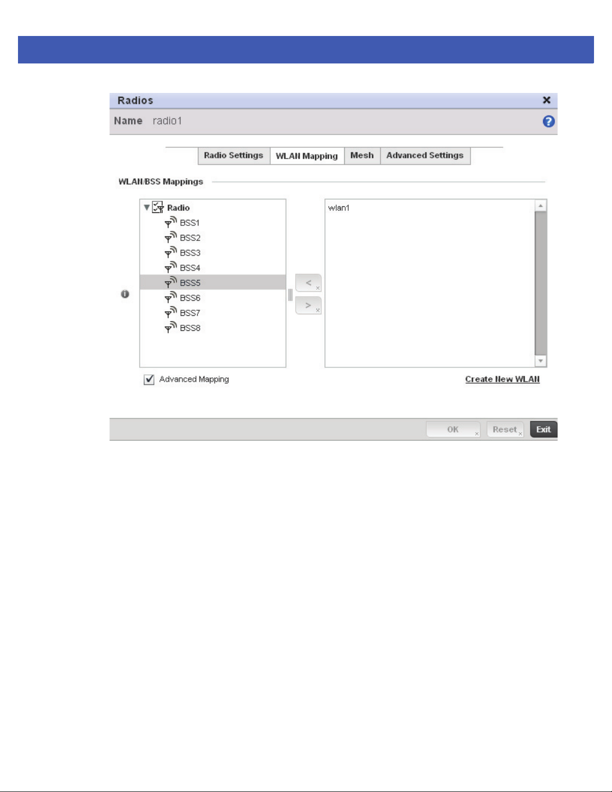
5 - 38 WiNG 5 Access Point System Reference Guide
Figure 5-18 Access Point Radio - WLAN Mapping tab
13. Refer to the WLAN/BSS Mappings field to set WLAN BSSID assignments for an existing access point deployment.
Administrators can assign each WLAN its own BSSID. If using a single-radio access point, there are 8 BSSIDs
available. If using a dual-radio access point there are 8 BSSIDs for the 802.11b/g/n radio and 8 BSSIDs for the
802.11a/n radio.
Each supported access point model can support up to 8 BSS IDs.
14. Select the OK button located at the bottom right of the screen to save the changes to the WLAN Mapping. Select
Reset to revert to the last saved configuration.
15. Select the Mesh tab.
Page 99
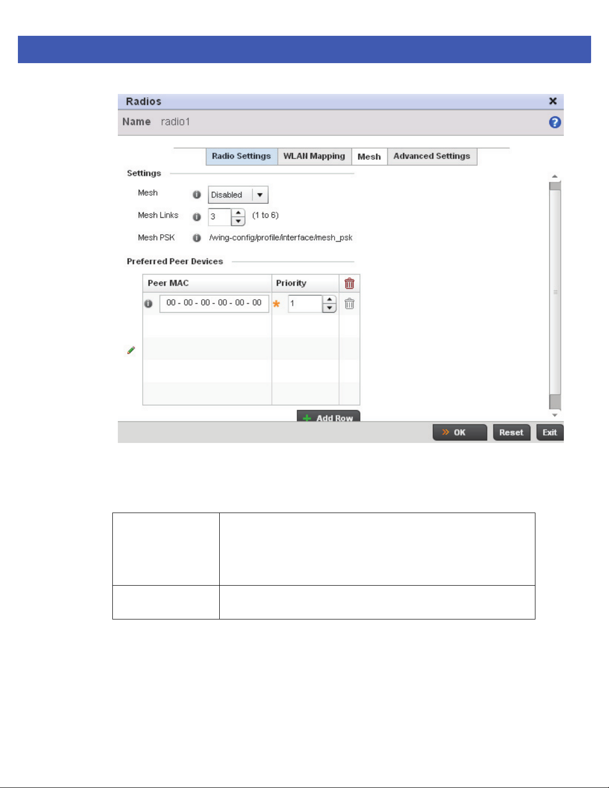
Device Configuration 5 - 39
Figure 5-19 Access Point Radio - Mesh tab
16. Use the Mesh screen to define how mesh connections are established and the number of links available amongst
access points within the Mesh network.
17. Define the following Mesh Settings:
Mesh Options include Client, Portal and Disabled. Select Client to scan for mesh
portals, or nodes that have connection to portals, and then connect through
them. Portal operation begins beaconing immediately and accepts connections
from other mesh supported nodes. Select Portal when setting a mesh
connection between two Standalone APs. The default value is Disabled.
Mesh Links Use the spinner control to define the number of mesh links (1 -6) an access
point radio will attempt to create. The default settings is 3 links.
18. Refer to the Preferred Peer Devices table and select + Add Row to define MAC addresses representing peer
devices for preferred mesh connection. Use the Priority spinner control to set a priority (1 -6) for connection preference.
19. Select the OK button located at the bottom right of the screen to save the changes to the Mesh configuration. Select
Reset to revert to the last saved configuration.
20. Select the Advanced Settings tab.
Page 100
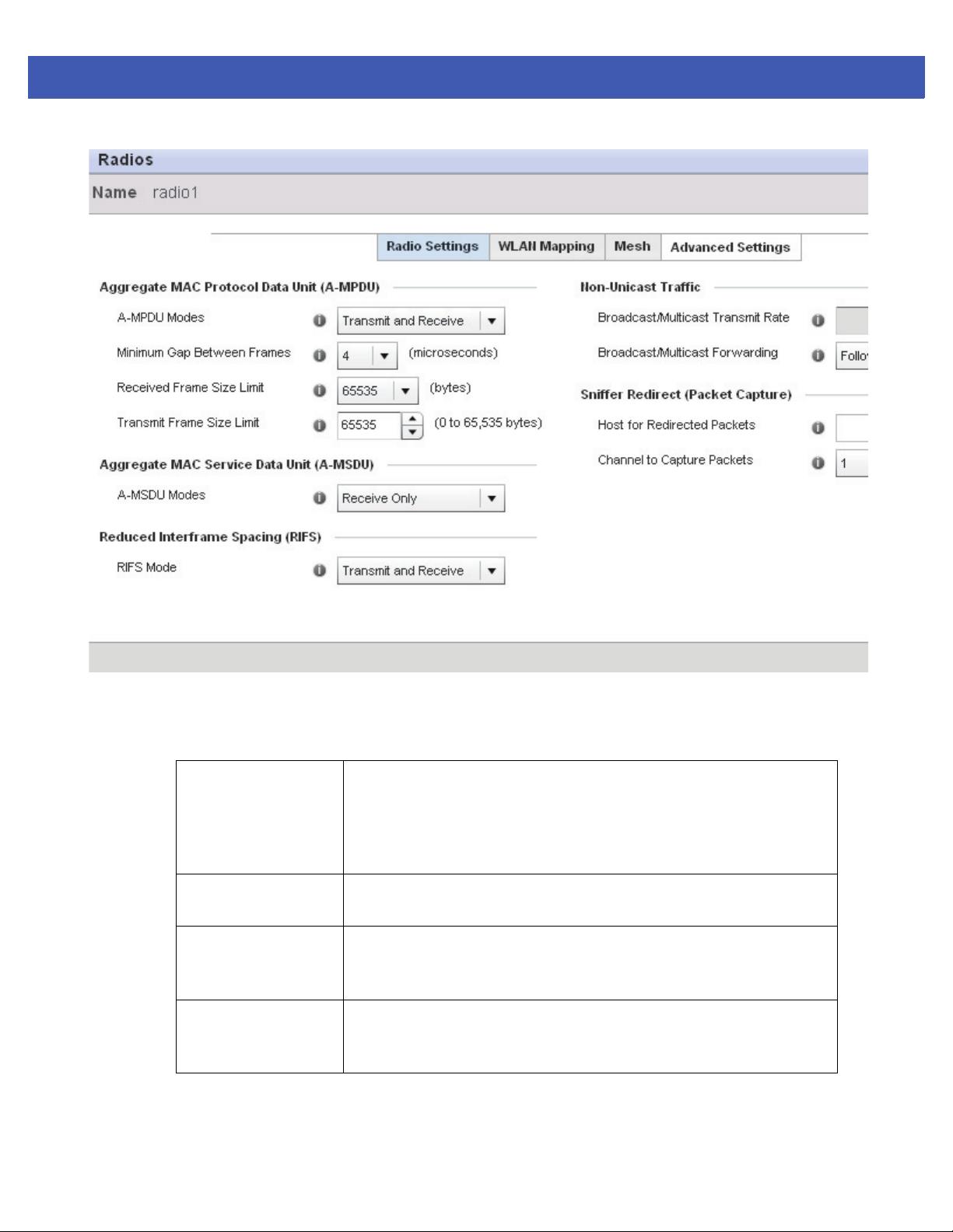
5 - 40 WiNG 5 Access Point System Reference Guide
Figure 5-20 Access Point Radio - Advanced Settings tab
21. Refer to the Aggregate MAC Protocol Data Unit (A-MPDU) field to define how MAC service frames are
aggregated by the access point radio.
A-MPDU Modes Use the drop-down menu to define the A-MPDU mode supported. Options
include Transmit Only, Receive Only, Transmit and Receive and None. The
default value is Transmit and Receive. Using the default value, long frames can
be both sent and received (up to 64 KB). When enabled, define either a
transmit or receive limit (or both).
Minimum Gap
Between Frames
Received Frame Size
Limit
Transmit Frame Size
Limit
22. Use the Aggregate MAC Service Data Unit (A-MSDU) drop-down menu to set the supported
A-MSDU mode.
Use the drop-down menu to define the minimum gap between A-MPDU frames
(in microseconds). The default value is 4 microseconds.
If a support mode is enable allowing A-MPDU frames to be received, define an
advertised maximum limit for received A-MPDU aggregated frames. Options
include 8191, 16383, 32767 or 65535 bytes. The default value is 65535 bytes.
Use the spinner control to set limit on transmitted A-MPDU aggregated
frames. The available range is between 0 - 65,535 bytes). The default value is
65535 bytes.
 Loading...