

motorola W160, W175, W180 Service Manual
6809515A16
Level 1-2 Service Manual
W160/W156/W180/W175/
W161/W181
Dual Band Wireless Telephone
W160/W156/W180/W175/W161/W181
GSM 900/1800
GSM 850/1900

Table of Contents W160/W156/W180/W175/W161/W181
Table of Contents
Introduction ................................................................................................................................... 4
Product Identification ............................................................................................................ 4
Product Names ..................................................................................................................... 4
Product Changes .................................................................................................................. 4
Regulatory Agency Compliance ........................................................................................... 4
Computer Program Copyrights ............................................................................................. 5
About This Service Manual ................................................................................................... 5
Warranty Service Policy ....................................................................................................... 6
Parts Replacement ............................................................................................................... 7
Specifications ................................................................................................................................ 8
Product Overview ........................................................................................................................ 10
Features ............................................................................................................................. 10
General Functions .............................................................................................................
Controls, Indicators, and Input/Output (I/O) Connectors .................................................... 12
User Interface Menu Structure ........................................................................................... 14
Battery Function ................................................................................................................. 15
Operation ............................................................................................................................ 15
Tools and Test Equipment ......................................................................................................... 15
Disassembly ................................................................................................................................ 16
Removing and Replacing the Battery ................................................................................. 17
Removing and Replacing the SIM Card ............................................................................. 18
Removing and Replacing the Front Housing ...................................................................... 19
Removing and Replacing the Transceiver Board, Shielding case, and Vibrator Module ... 22
Removing and Replacing the Antenna Module, Microphone ............................................. 24
Subscriber Identity Module (SIM) and Identification Label ..................................................... 26
SIM ..................................................................................................................................... 26
Identification ....................................................................................................................... 26
Troubleshooting .......................................................................................................................... 28
Manual Test Mode .............................................................................................................. 28
Manual Test Mode Commands .......................................................................................... 28
Troubleshooting Chart ........................................................................................................ 29
Programming: Software Upgrade and Flexing ................................................................... 30
Part Number Charts .................................................................................................................... 31
Exploded View Diagram (W160) ........................................................................................ 31
Exploded View Parts List (W160) ....................................................................................... 32
Exploded View Diagram (W156) ........................................................................................ 33
Exploded View Parts List (W156) ....................................................................................... 34
.......... 12
2 12-December-2007

Table of Contents W160/W156/W180/W175/W161/W181
Exploded View Diagram (W180) ........................................................................................ 35
Exploded View Parts List (W180) ....................................................................................... 36
Exploded View Diagram (W175) ........................................................................................ 37
Exploded View Parts List (W175) ....................................................................................... 38
Exploded View Diagram (W161) ........................................................................................ 39
Exploded View Parts List (W161) ....................................................................................... 40
Exploded View Diagram (W181) ........................................................................................ 41
Exploded View Parts List (W181) ....................................................................................... 42
Accessories ........................................................................................................................ 43
Index ............................................................................................................................................... 1
3 12-December-2007

Level 1-2 Service Manual
Introduction
Product Identification
Product Names
Motorola® Inc. maintains a worldwide organization that is dedicated to provide responsive,
full-service customer support. Motorola products are serviced by an international network of
company-operated product care centers as well as authorized independent service firms.
Available on a contract basis, Motorola Inc. offers comprehensive maintenance and installation
programs that enable customers to meet requirements for reliable, continuous communications.
To learn more about the wide range of Motorola service programs, contact your local Motorola
products representative or the nearest Customer Service Manager.
The model number on a label (usually on the housing) identifies Motorola products. Use the entire model number when inquiring about the product. Numbers are also assigned to chassis and kits.
Use these numbers when requesting information or ordering replacement parts.
Product names are listed on the front cover. Product names are subject to change without notice. Some product names, as well as some frequency bands, are available only in certain markets.
Product Changes
When electrical, mechanical or production changes are incorporated into Motorola products, a
revision letter is assigned to the chassis or kit affected, for example: -A, -B, or -C, and so on.
The chassis or kit number, complete with revision number is imprinted during production. The
revision letter is an integral part of the chassis or kit number and is also listed on schematic
diagrams, and printed circuit board layouts.
Regulatory Agency Compliance
This device complies with Part 15 of the FCC Rules. Operation is subject to the following conditions:
• This device may not cause any harmful interference, and
• this device must accept interference received, including interference that may cause
undesired operation
This class B device also complies with all requirements of the Canadian Interference-Causing Equipment Regulations (ICES-003).
Cet appareil numerique de la classe B respecte toutes les exigences du Reglement sur le materiel brouilleur du Canada.
12-December-2007 4

Computer Program Copyrights
The Motorola products described in this manual may include Motorola computer programs
stored in semiconductor memories or other media that are copyrighted with all rights reserved
worldwide to Motorola. Laws in the United States and other countries preserve for Motorola,
Inc. certain exclusive rights to the copyrighted Introduction computer programs, including the
exclusive right to copy, reproduce, modify, decompile, disassemble, and reverse-engineer the
Motorola computer programs in any manner or form without Motorola's prior written consent.
Furthermore, the purchase of Motorola products shall not be deemed to grant either directly or
by implication, estoppel, or otherwise, any license or rights under the copyrights, patents, or
patent applications of Motorola, except for a nonexclusive license to use the Motorola product
and the Motorola computer programs with the Motorola product.
About This Service Manual
Using this service manual and the suggestions contained in it assures proper installation,
operation, and maintenance of W160/W156/W180/W175/W161/W181 telephones. Refer
questions about this manual to the nearest Customer Service Manager. This manual contains
mechanical service information required for the equipment described and is current as of the
printing date.
W160/W156/W180/W175/W161/W181
Audience
This document aids service personnel in testing and repairing W160/W156/W180/W175/
W161/W181 telephones Service personnel should be familiar with electronic assembly,
testing, and troubleshooting methods, and with the operation and use of associated test
equipment.
Scope
This manual provides basic information relating to W160/W156/W180/W175/W161/W181 telephones, and also provides procedures and processes for repairing the units at Level 1 and 2 service centers, including:
• Unit swap out
• Repairing of mechanical faults
• Basic modular troubleshooting
• Testing and verification of unit functionality
• Initiate warranty claims and send faulty modules to Level 3 or 4 repair centers.
5 12-December-2007
Level 1-2 Service Manual
M Keys to be pressed are represented graphically. For example, instead of "Press the Menu Key",
Conventions
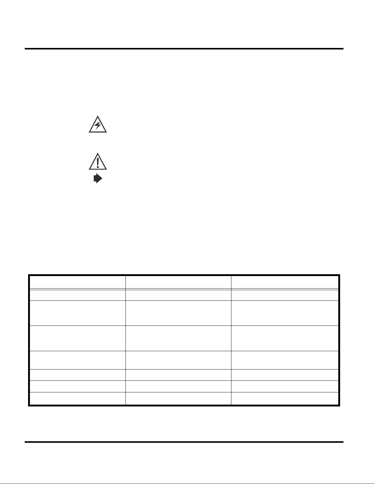
Special characters and typefaces, listed and described below, are used in this publication to emphasize certain types of information.
Note: Emphasizes additional information pertinent to the subject matter.
Caution: Emphasizes information about actions that may result in equipment damage.
Waring: Emphasizes information about actions that may result in personal injury.
you will see "Press
Information from a screen is shown in text as similar as possible to what appears in the display.
For example, ALERTS or
Information that you need to type is printed in boldface type.
M".
ALERTS.
Warranty Service Policy
The product is sold with the standard 12-month warranty terms and conditions. Accidental damage, misuse, and extended warranties offered by retailers are not supported under warranty.
Non-warranty repairs are available at agreed fixed repair prices.
Out of Box Failure Policy
The standard out of box failure criteria applies. Customer phones that fail very early on after
the date of sale are to be returned to Manufacturing for root cause analysis, to guard against
epidemic criteria. Manufacturing to bear the costs of early life failure.
Product Support
The customer's original phones will be repaired but not refurbished as standard. Appointed
Motorola Service Hubs will perform warranty and non-warranty field service for level 2
(assemblies) and level 3 (limited Transceiver component). Motorola High Tech Centers will
perform level 4 (full component) repairs.
Customer Support
Customer support is available through dedicated Call Centers and in-country help desks. Product-Service training should be arranged through the local Motorola Support Center.
12-December-2007 6

Parts Replacement
W160/W156/W180/W175/W161/W181
When ordering replacement parts or equipment, include the Motorola part number and
description used in the service manual. When the Motorola part number of a component is not
known, use the product model number or other related major assembly along with a
description of the related major assembly and of the component in question. In the U.S.A., to
contact Motorola, Inc. on your TTY, call: 800-793-7834
Accessories and Aftermarket Division (AAD)
Replacement parts, test equipment, and manuals can be ordered from AAD.
U.S.A. Outside U.S.A.
Phone: 800-422-4210 Phone: 847-538-8023
FAX: 800-622-6210 FAX: 847-576-3023
For EMEA spare parts call +49 461 803 1638.
For Asia spare parts call +65 648 62995.
7 12-December-2007

Level 1-2 Service Manual
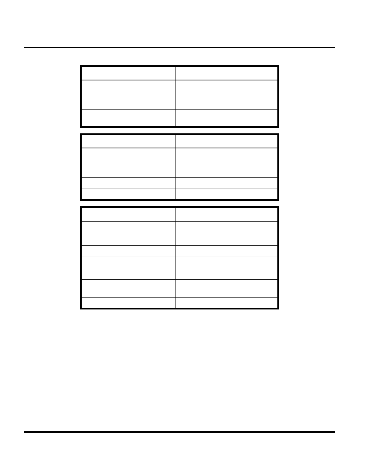
Specifications
Dimensions 113.2mm x 42.0mm x 14.0mm
Weight 84grams (with battery)
LCD Display 65K Color CSTN(MT);Mono STN(LT)
Band GSM900/1800 or GSM850/PCS1900
Battery 910 mAh Li Ion Battery
Product type BAR type
Antenna Internal Antenna
Frequency Range (EGSM) 880-915 MHz Tx,
General Functions Specification
Active Area: 27.264mm x
27.264mm(MT); 28.79 x 28.79 mm(LT)
Hardware pixels: 128 x 128
925-960 MHz Rx
Frequency Range (DCS) 1710 – 1785 MHz Tx,
1805-1880 MHz Rx
Frequency Range (GSM850) 824-849 MHz Tx,
869-894 MHz Rx
Frequency Range (PCS) 1850-1910MHz Tx,
1930-1990 MHz Rx
Channel Spacing 200KHz
Channels 174 EGSM, 374 DCS,
124 GSM850, 299 PCS
Modulation GMSK at BT=0.3
Transmitter Phase Accuracy 5 Degrees RMS, 20 Degrees peak
Duplex spacing 45MHz EGSM, 95MHz DCS,
45MHz GSM850, 80MHz PCS
Frequency Stability ±0.1PPM of the downlink frequency (Rx)
Operating voltage 3.53V ~4.2V
Average Transmit Current Power Level 5: 175 mA
Power Level 19: 90 mA
Average Standby Current DRX 2: 4.0 mA
DRX 9: 1.9 mA
Temperature Range -10°C to 55°C
Battery Life Talk Time: 250-500 Mins; Stand by Time:
150~300 Hours
Battery Charge Time 4 Hours to 90% of 940mAH capacity
Alert Volume Max 95dB@ 5cm, 0.5 watts input
12-December-2007 8
W160/W156/W180/W175/W161/W181
Transmitter Functions Specification
RF Power Output 33 dBm typical GSM850/GSM900
30 dBm typical DCS1800/PCS1900
Output Impedance 50 ohms nominal
Spurious Emissions -36 dBm from 0.1 to 1GHz,
-30 dBm from 1 to 4 GHz
Receiver Functions Specification
Receiver Sensitivity -107 dBm typical GSM 850/GSM900
-107 dBm typical DCS1800/PCS1900
RX Bit Error Rate (100K bits) type II <2%
Channel Hop Time 500 microseconds
Time to Camp Approximately 6~10 Second
Speech Coding Functions Specification
Speech Coding Type Regular pulse excitation/linear predictive
coding with long term prediction (PRE
LPC with LTP)
Bit Rate 13.0 Kbps
Frame Duration 20 ms
Block Length 260 bits
Classes Class 1 bits =182 bits;
Class 2 bits = 78 bits
Bit Rate with FEC Encoding 22.8 Kbps
9 12-December-2007

Level 1-2 Service Manual
Product Overview
The Motorola W160/W156/W180/W175/W161/W181 features a global system for mobile
communications wireless interface technology. It also features a simplified icon and graphical
user interface (UI) for easier operation in addition to short message service text messaging
(SMS), speed dialing, quick dialing, an alarm, a calculator, games, and an address book. The
W160/W156/W180/W175/W161/W181 is a dual-band phone that allows for roaming within
the EGSM900 / DCS1800 or GSM850 / PCS 1900.
The telephones are made of polycarbonate plastic. The display and speaker, as well as the 21key keypad, transceiver printed circuit board (PCB), microphone, charger and headphone
connectors, and power button are contained within clam shell form-factor housing. The
Userreplaceable 910 mAh Lithium-Ion (Li-Ion) battery provide up to 238-469 Mins of talk
time with up to 133-307 Hours of standby time. The phone accepts 1.8V/3V mini subscriber
identity module (SIM) cards that fit into the SIM holder next to the battery. These telephones
feature a 128 x 128 pixel Depends on LBI LT(gray) or MT(color). display and an internal
antenna.
Features
W160/W156/W180/W175/W161/W181 telephones use advanced, self-contained, sealed,
custom integrated circuits to perform the complex functions required for GSM GPRS
communication. Aside from the space and weight advantage, microcircuits enhance basic
reliability, simplify maintenance, and provide a wide variety of operational functions.
Features available in this family of telephones include:
• A 128 x 128 pixel color graphics (Depends on LT or MT) display
• Internal antenna
• Lower voltage technology that provides increased standby and talk times
• Extended GSM (EGSM) channels
• Display animation (Depends on LT or MT)
• VibraCall® vibrating alert
• 5-Way navigation key
• SIM Toolkit™ Class 2 (STK) (Network, subscription and SIM card or service provider
• Backlight
• Speed-, Quick- and One-Touch dialing
• Call Forwarding and Holding
• Customized Menus
• Personal management tools calculator with currency converter, and clock with date
• Other features
dependent feature. Not available in all areas.)
12-December-2007 10
W160/W156/W180/W175/W161/W181
Caller Line Identification
Upon receipt of a call, the calling party's phone number is compared to the phone book. If the
number matches a phone book entry, that name will be displayed. If there is no phone book
entry, the incoming phone number will be displayed. In the event that no caller identification
information is available, an incoming call message is displayed.
Simplified Text Entry
The W160/W156/W180/W175/W161/W181 features iTAP™ predictive text entry. Press a key
to generate a character and a dynamic dictionary uses this to build and display a set of word or
name options. The iTAP™ feature may not be available on the phone in all languages.
SIM Toolkit™ - Class 2
SIM Application Toolkit is a value-added service delivery mechanism that allows GSM
operators to customize the services they offer their customers, from the occasional user who
requests sports news and traffic alerts, to a high call time business user who receives stock
alerts and checks flight times. Operators can now create their own value-added services menu
quickly and easily in the phone.
The customized menu will appear as the first menu and may be updated over-the-air with new services when customers request them.
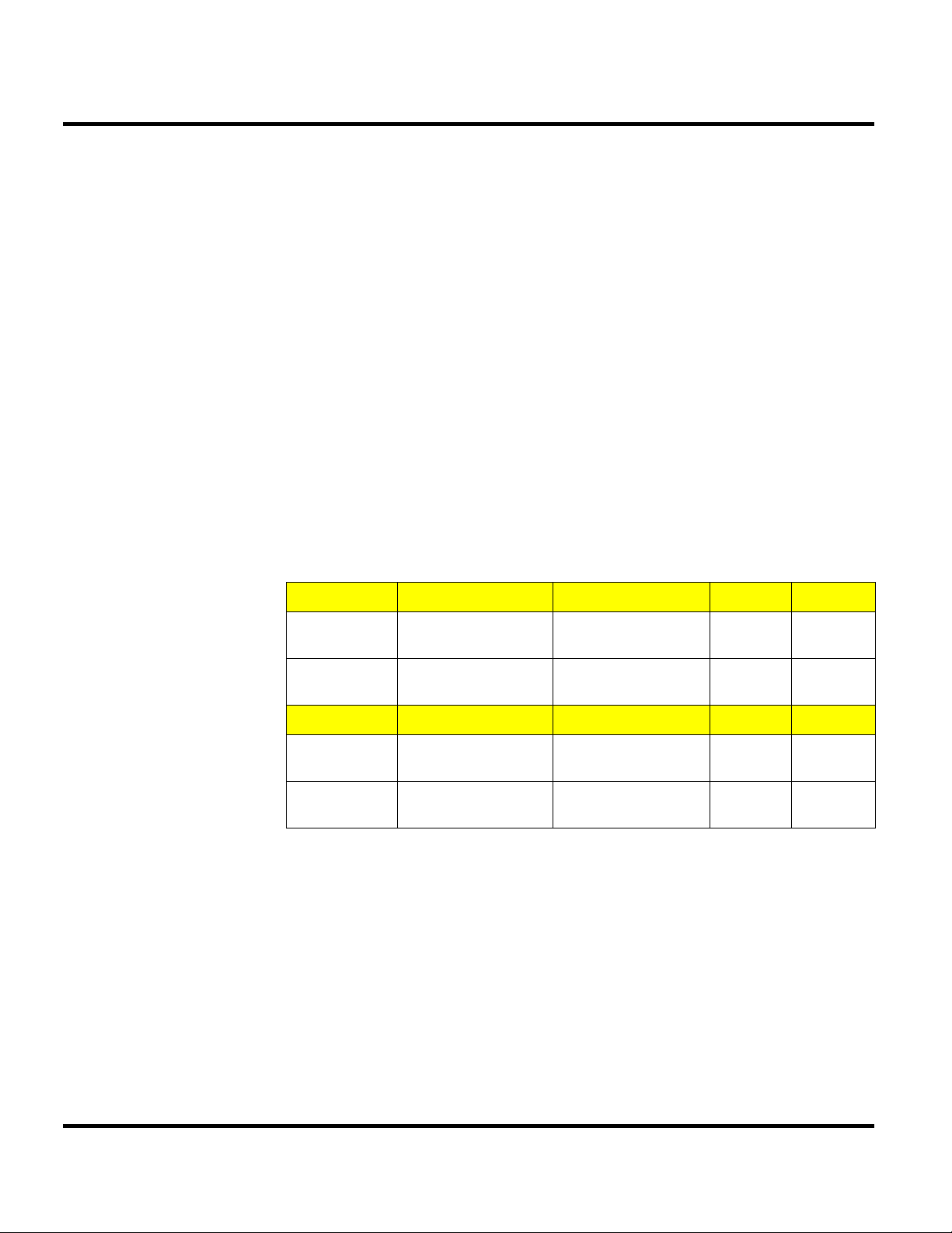
LBI_MT/LT_Comparison Chart
LBI_LT Band LCD FM Radio MEMORY
W160/W161 GSM 900/1800,
GSM 850/1900
W156 GSM 900/1800,
GSM 850/1900
LBI_MT Band LCD FM Radio MEMORY
W180/W181 GSM 900/1800,
GSM 850/1900
W175 GSM 900/1800,
GSM 850/1900
Mono STN 128*128 YES 32/16
Mono STN 128*128 NO 32/16
CSTN 128*128 YES 64/16
CSTN 128*128 NO 64/16
Other Features
Detailed descriptions of the other features can be found in the appropriate W160/W156/W180/ W175/W161/W181 telephone user guides listed in the Related Publications section at the end of this manual.
11 12-December-2007
Level 1-2 Service Manual
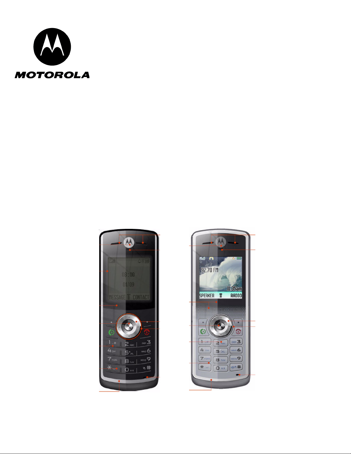
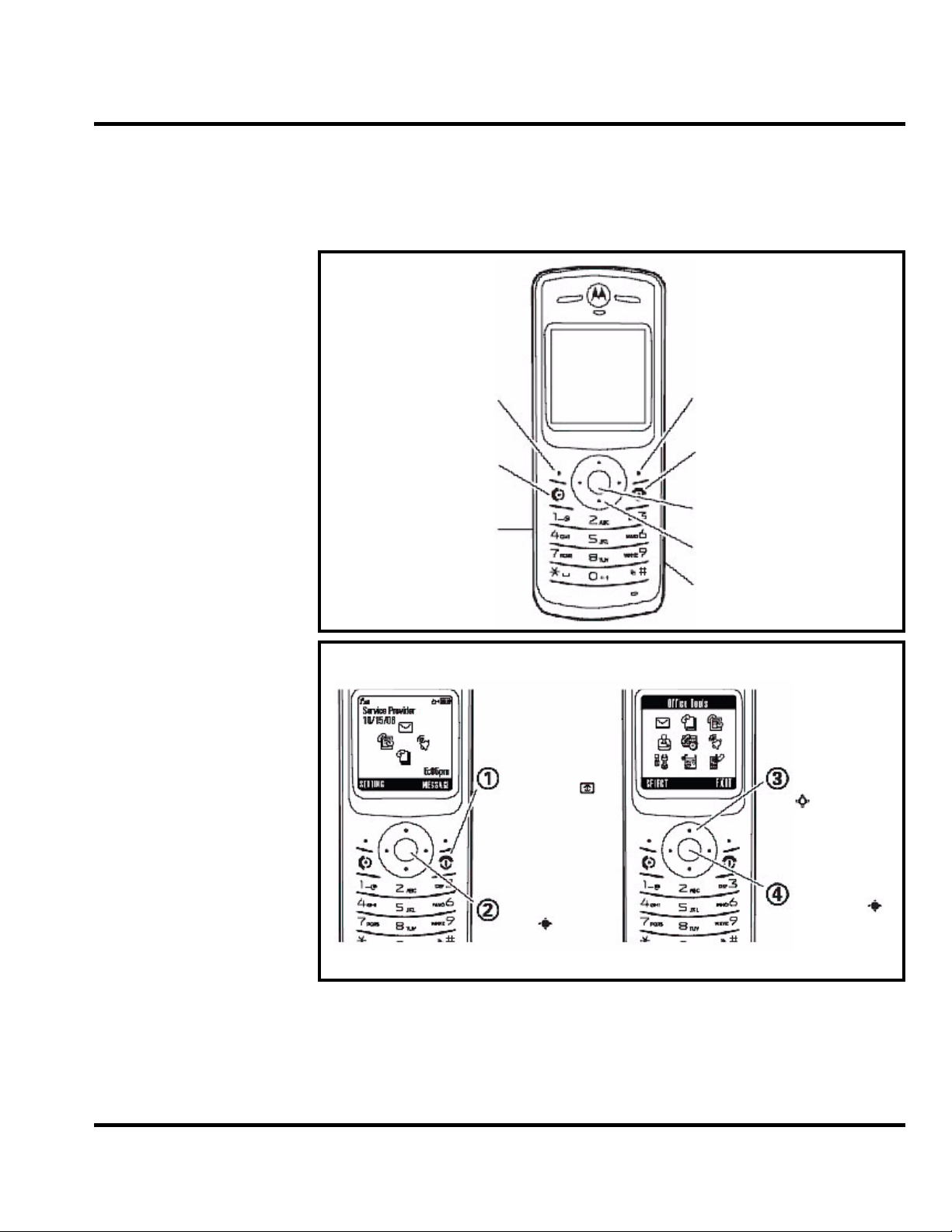
Right Soft Key
Left Soft Key
Make & answer calls.
Listen to music.
Turn on & off, hang up,
exit menues.
Open menus.
Navigate menus.
Charge up.
NOTE: don’t support
connection to PCs.
Home Screen
Main Menu
Press & hold the
power key
until the display
lights up, to turn
on your phone.
Press the
center
key
to open
the Main Menu.
Press the
center key
to select it.
Press the
navigation key
up/down/left/
right to scroll to
a menu feature.
General Functions
Controls, Indicators, and Input/Output (I/O) Connectors
The W160/W156/W180/W175/W161/W181 phone's controls are located on the front side of the device and on the keyboard as shown in below. Indicators icons are displayed on the LCD.
Figure 1. W160/W156/W180/W175/W161/W181 Telephone Control Locations
Menu Navigation
W160/W156/W180/W175/W161/W181 telephones are equipped with a simplified icon and
graphical-based user interface. See the table below for details of the W160/W156/W180/
W175/W161/W181 menu structure. A five-way navigation key allows you to move easily
through menus and confirm your selection.
12-December-2007 12
W160/W156/W180/W175/W161/W181
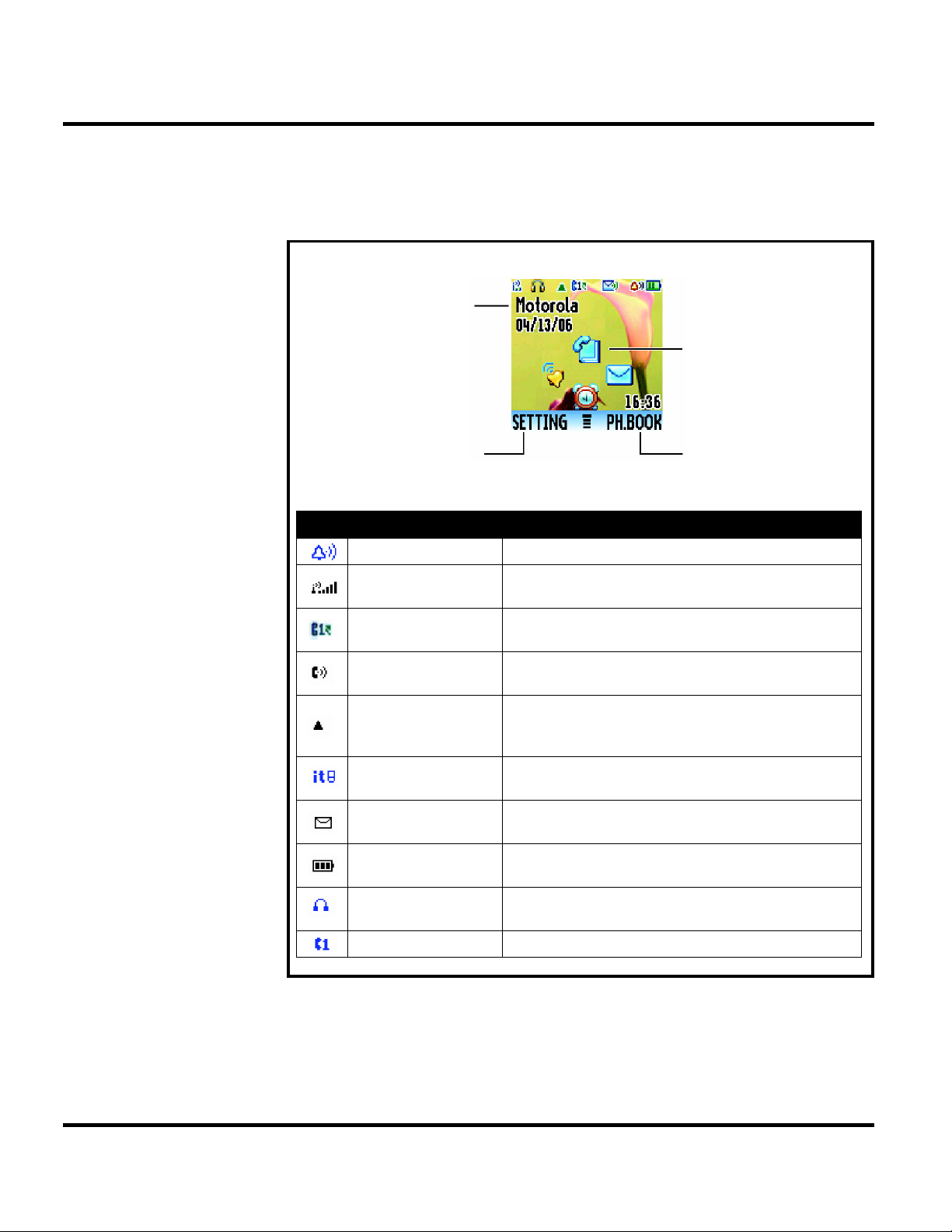
Icon
Name
Description
Alert Type Indicator displays your assigned ring type.
Signal Strength
Indicator
shows when Call Forward is activated.
Call Forward
Indicator
shows when Call Forward is activated.
In Use Indicator
indicates when a call is in progress, and when you have
a secure or insecure connection.
Roam Indicator
appears when your phone uses another network system
outside your home network. Icon here can also indicate
your text entry mode, alpha, numeric, symbol and etc.
Entry Method
Indicator
appears when you select a specific kind of entry method.
Message Indicator
appears when you have a new voice or text message
waiting.
Battery Level
Indicator
shows the amount of charge left in your battery. The
more the bars, the greater the charge.
Headset Indicator
When you plug the headset to your phone, the icon
displays.
LINE Indicator indicates your phone is using LINE 1 or LINE 2.
Right Soft Key Label
Left Soft Key Label
Home Screen Display
Service Provider
Liquid Crystal Display (LCD)
The LCD provides a 700 square millimeter multicolor backlit color display with useradjustable contrast settings for optimum readability in all light conditions. The bit-map 128 x
128 pixel display includes up to 3 lines of text, 1 line of icons, and 1 line of prompts.
Figure 2. Display Icon Indicators
13 12-December-2007
Level 1-2 Service Manual
Menu Map (LBI_LT)
main menu
e Messages
• Create Message
•Voicemail
• Inbox
• Info Services
• Quick Notes
• Outbox
•Drafts
n Phonebook
• [New Entry]
s Recent Calls
• Received Calls
• Dialed Calls
• Notepad
•Call Times
• Call Cost
Q Games
• Spring Ball
• FootBall
•Maze
É Office Tools
• Calculator
• MyMenu
• Alarm Clock
• Calendar
• Stop Watch
• Quick Dial
• Fixed Dial
• Service Dial
•STK *
t Ring Styles
•Style
• Ring Detail
• My Tones
w Settings
• (see next page)
r FM Radio
l Personalize
• Home Screen
• Main Menu
• Greeting
• Quick Dial
* Network Dependent
Provided on the W160
only
This is the standard main
menu layout.
Your phone’s menu
may be different.
setting menu
Call Forward
• Voice Calls
• Cancel All
• Forward Status
Phone Status
• My Tel. Numbers *
• Active Line *
• Battery Meter
In-Call Setup
•In-Call Timer
• Call Cost Setup
• My Caller ID
• Answer Options
• Call Waiting
Security
• Phone Lock
• Lock Keypad
• Lock Keypad Timer
• Fixed Dial
• Call Barring
•SIM PIN
• New Passwords
Initial Setup
• Time and Date
• Power on/off
• 1-Touch Dial
• Backlight
•Scroll
• Language
• Display Timeout
• Contrast
•DTMF
•TTY Setup
• Master Reset
• Master Clear
Network
•New Network
•Network Setup
• Avail. Networks
• My Network List
• Service Tone
• Call Drop Tone
• Band Selection
Headset
• Auto Answer
* Network Dependent
User Interface Menu Structure
The table below shows a portion of the W160/W156/W180/W175/W161/W181 telephone menu structure.
Figure 3. W160/W156/W180/W175/W161/W181 Menu Structure
12-December-2007 14
Battery Function
Operation
W160/W156/W180/W175/W161/W181
The telephone displays a battery charge indicator icon in the idle screen to indicate the battery charge level. The gauge shows four levels: 50%, 20%, 5%, and Low Battery.
Removing the battery causes the phone to shut down immediately and loose any pending work (partially entered phone book entries or outgoing messages, for example).
Note: All batteries can cause property damage and/or bodily injury such as burns if a
conductive material such as jewelry, keys, or beaded chains touches exposed terminals. The
conductive material may complete an electrical circuit (short circuit) and become quite hot.
Exercise care in handling any charged battery, particularly when placing it inside a pocket,
purse, or other container with metal objects.
If the battery is removed while receiving a message, the message is lost.
To ensure proper memory retention, turn the phone OFF before removing the
battery.Immediately replace the old battery with a fresh battery.
For detailed operating instructions, refer to the appropriate User Guide.
Tools and Test Equipment
The table below lists the tools and test equipment used on W215 telephones. Use either the listed items or the equivalent.
Table 1: General Test Equipment and Tools
Motorola Part Number
See Table 3 Charger Used to charge battery and power phone
0180386A82 Antistatic Mat Kit (includes 66-80387A95
- Antistatic Gloves Provides protection from damage to
0-00-00-3005 (AMS) Disassembly tool, plastic with flat and
6680388B01 Tweezers, plastic Used during assembly/disassembly
- T5 Screw driver Used with Screw Driver
1
antistatic mat, 66-80334B36 ground
cord, and 42-80385A59 wrist band)
pointed ends (manual opening tool)
Description Application
Provides protection from damage to
phone caused by electrostatic discharge
(ESD)
phone caused by electrostatic discharge
(ESD)
Used during assembly/disassembly
HP34401A
2
Digital Multimeter Used to measure battery voltage
15 12-December-2007
 Loading...