

Page 1
prOgraMMable FunctiOnS/FeatureS
IP57 Submersible (1 m/30 min.
Programmable Function Keys
2-tone Encode/Decode
5-tone Encode/Decode
MDC-1200
Scan
Group Scan
Dual Watch
FM-Scan (Follow-Me Scan
TA Scan
Encryption
Clear Voice
VOX
REC & PLAY (Requires DVS-9
AF Min Volume
Talk Around
Man Down (Requires DVS-9
Emergency
Lone Worker
Direct Channel Entry
Code Up/Down
Code Set
Speed Dial
DTMF Code Set
ID Check
TX Save Disable
ARTS (Auto Range Transpond System
1:
2: VX-459 Only
®
Encode/Decode
1
1
1
1
2
1
VX-454 & VX-459 Only
)
)
)
)
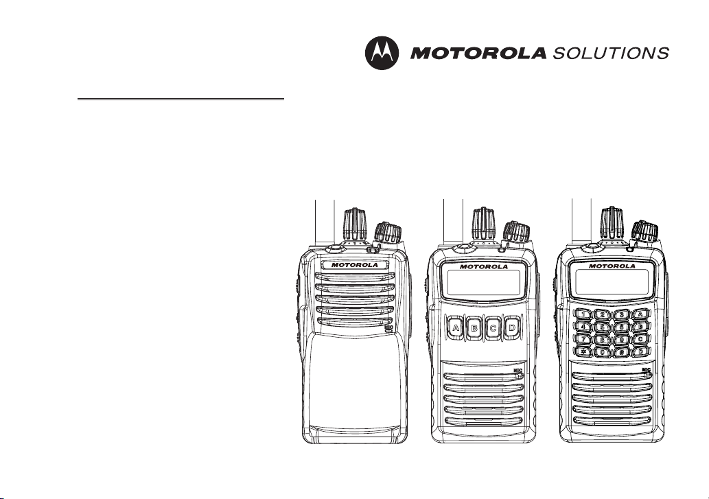
VX-450 SerieS
Operating Manual
)
VX-451 VX-454 VX-459
Page 2

cOntentS
Important Note .........................................................1
Introduction ..............................................................2
Intrinsic Safety (IS) Information ............................3
Important Safety Information ................................4
Consignes de sécurité importantes .........................6
Controls & Connectors (VX-459) ........................... 8
Controls & Connectors (VX-454) ........................... 9
Controls & Connectors (VX-451) ......................... 10
LCD Icons & Indicators (VX-454 & VX-459) ..... 11
Before You Begin ....................................................12
Battery Pack Installation and Removal .............12
Battery Charging (VAC-UNI: CD-58/PA-55) ...14
Low Battery Indication ......................................15
Belt Clip Installation and Removal ...................16
MIC/SP CAP Installation ...................................17
Operation ................................................................ 18
Preliminary Steps ...............................................18
Operation Quick Start ........................................18
Automatic Time-Out Timer ...............................21
Advanced Operation ..............................................21
Programmable Key Functions ..........................21
Description of Operating Functions .................24
Lock .........................................................................38
Man Down Function ..............................................38
ARTS (Auto Range Transpond System) ..............38
User Set Mode.........................................................39
Optional Accessories ..............................................40
Warranty Policy ..................................................... 42
Page 3

Congratulations!
You now have at your ngertips a valuable communications tool-a Motorola Solutions two-way radio! Rugged, reliable and easy to use, your Motorola Solutions radio will keep you in constant touch with your colleagues for years
to come, with negligible maintenance down-time. Please take a few minutes to read this manual carefully. The information presented here will allow you to derive maximum performance from your radio, in case questions arise
later on.
Important Note
There are no owner-serviceable parts inside the radio. All service jobs must be referred to an authorized
r
Motorola Solutions Service Representative. Consult your Authorized Motorola Solutions Dealer for installation of optional accessories.
In order to maintain the specied water integrity performance, periodic maintenance is recommended.
r
Should the radio sustain a severe shock (e.g. if it is dropped), the water integrity may be compromised,
r
requiring service. Should this occur, contact your Authorized Motorola Solutions Dealer.
Important Notice for North American Users Regarding 406 MHz Guard Band
The U.S. Coast Guard and National Oceanographic and Atmospheric Administration have requested the
cooperation of the U.S. Federal Communications Commission in preserving the integrity of the protected
frequency range 406.0 to 406.1 MHz, which is reserved for use by distress beacons. Do not attempt to program this apparatus, under any circumstances, for operation in the frequency range 406.0 - 406.1 MHz if
the apparatus is to be used in or near North America.
Warning - Frequency band 406 - 406.1 MHz is reserved for use ONLY as a distress beacon by the US Coast
Guard and NOAA. Under no circumstance should this frequency band be part of the pre-programmed operating frequencies of this radio.
VX-450 SerieS Operating Manual 1
Page 4

VX-450 SerieS Operating Manual
IntroductIon
The
VX-451
groups which can each be programmed with an 8-character Alpha-Numeric Tag.
allows to 32-channel capacity and 2 groups. The
VX-454/-459
allows to 512-channel capacity and 32
The IS version of the
Intrinsic Safety. These transceivers are designed for reliable business communications in the VHF or UHF Land
Mobile bands with a wide variety of applications with a wide range of operating capability provided by their leading-edge design.
Caution: To acquire the IS version of the
time of purchase.
Important channel frequency data is stored in EEPROM and ash memory on the CPU, and is easily programmable
by Motorola Solutions dealers using a personal computer and the Motorola Solutions Programming Cable and
Software.
CE115
The pages which follow will detail the many advanced features provided in the
reading this manual, you may wish to consult with your Network Administrator regarding precise details of the
conguration of this equipment for use in your application.
VX-450
2
series are full-featured hand-held FM transceivers which meets the requirements of
VX-450
series you much select the Intrinsically Safe battery option at the
VX-450
series transceiver. After
Page 5

VX-450 SerieS Operating Manual
IntrInsIc safety
IS version of the
ANSI/UL 913 5th Edition for Class I, II, III, Division 1, Groups C, D, E, F, G, T3C hazardous locations.
Battery Packs:
Speaker Microphone:
Behind Type VOX Compatible Microphone:
Over the Head VOX Compatible Microphone:
Man Down Alert with Digital Voice Storage Unit:
ANI & Encryption Unit:
Never charge the battery in the hazard areas.
r
Never install/removal the battery in the hazard areas.
r
Never install/remove the optional unit (includes the Speaker/Microphone and VOX Headset) in the hazard areas.
r
The
r
charged by the rapid ow of a non-conductive media.
Ensure that there is no external damage to the radio, antenna or battery before entering the potentially explosive
r
atmospheres, as it might compromise the safety of the unit. eg an antenna with a damaged end or insulation
must be replaced before use in any potentially explosive atmospheres.
Substitution of components may impair intrinsic safety. Installation of
r
normal
To acquire the IS version of the
r
of purchase.
Securite Intrinseque, AVERTISSEMENT – AFIN DE PREVENIR L’INFLAMMATION D’ATMOSPHERES
r
DANGEREUSES, NE CHANGER LES BATTERIES QUE DANS DES EMPLACEMENTS DESIGNES
NON DANGEREUX.
shall not be directly installed or used in any process where its enclosure might be electrostatically
VX-450
VX-450
series is equipped with any of the following optional units, meets the requirements of
VX-450
into IS version.
VX-450
series you much select the Intrinsically Safe battery option at the time
(Is)
InformatIon
FNB-V134LIIS-UNI
A4B
MH-66
VH-150A
VH-150B
DVS-9
FVP-44
FNB-V134LIIS-UNI
does NOT convert
3
Page 6

VX-450 SerieS Operating Manual
Important safety InformatIon
englIsh
ATTENTION!
This radio is restricted to Occupational use only. Before using the radio, read the RF Energy Exposure and Prod-
uct Safety Guide for Portable Two-Way Radios which contains important operating instructions for safe usage and
RF energy awareness and control for Compliance with applicable standards and Regulations.
For a list of Motorola Solutions-approved antennas and other accessories, visit the following website:
http://www.motorolasolutions.com
Any modication to this device, not expressly authorized by Motorola Solutions, may void the user’s authority to
operate this device.
Under Industry Canada regulations, this radio transmitter may only operate using an antenna of a type and maximum (or lesser) gain approved for the transmitter by Industry Canada. To reduce potential radio interference to
other users, the antenna type and its gain should be so chosen that the equivalent isotropically radiated power (e.i.r.p.)
is not more than that necessary for successful communication.
This radio transmitter has been approved by Industry Canada to operate with Motorola Solutions-approved antenna
with the maximum permissible gain and required antenna impedance for each antenna type indicated. Antenna
types not included in this list, having a gain greater than the maximum gain indicated for that type, are strictly prohibited for use with this device.
4
Page 7

VX-450 SerieS Operating Manual
Important safety InformatIon
englIsh
Notice to Users (FCC and Industry Canada)
This device complies with Part 15 of the FCC rules and Industry Canada’s license-exempt RSS’s per the following
conditions:
• This device may not cause harmful interference.
• This device must accept any interference received, including interference that may cause undesired operation.
• Changes or modications made to this device, not expressly approved by Motorola Solutions, could void the authority of the user to operate this equipment.
5
Page 8

VX-450 SerieS Operating Manual
consIgnes de sécurIté Importantes
french
ATTENTION!
Cette radio ne doit être utilisée qu’à des ns professionnelles. Avant d’utiliser la radio, lisez le guide Radios bidirectionnelles portatives : exposition aux radiofréquences et sécurité du produit, qui contient d’importantes instructions de fonctionnement pour une utilisation sécuritaire et des informations sur l’exposition aux fréquences
radioélectriques, dans le but d’assurer votre conformité aux normes et règlements en vigueur.
Visitez le site Web suivant pour obtenir la liste des antennes et autres accessoires approuvés par Motorola Solutions:
http://www.motorolasolutions.com
Toute modification effectuée à cet appareil sans l’autorisation explicite de Motorola Solutions peut annuler
l’autorisation d’utiliser cet appareil.
Selon la réglementation d’Industrie Canada, cet émetteur radio ne peut être utilisé qu’avec une antenne dont le type
et le gain maximal (ou minimal) sont approuvés par
Industrie Canada pour cet émetteur. An de limiter les interférences radio pour les autres utilisateurs, le type et le
gain de l’antenne doivent être choisis de façon à ce que la puissance isotrope rayonnée équivalente (P.I.R.E.) ne soit
pas plus forte qu’il ne le faut pour établir la communication.
Cet émetteur radio a été approuvé par Industrie Canada pour utilisation avec une antenne approuvée par Motorola
Solutions offrant le gain maximal autorisé et l’impédance requise pour le type d’antenne indiqué. Il est strictement
interdit d’utiliser avec cet appareil tout type d’antenne ne gurant pas dans cette liste et présentant un gain supérieur au maximum indiqué pour le type.
6
Page 9

VX-450 SerieS Operating Manual
consIgnes de sécurIté Importantes
french
Avis aux utilisateurs (FCC et Industrie Canada)
Le présent appareil est conforme aux CNR d’Industrie Canada applicables aux appareils radio exempts de licence
et à la partie 15 des règlements de la FCC.
• Cet appareil ne doit pas causer d’interférence nuisible.
• Cet appareil doit accepter toute interférence reçue, y compris les interférences pouvant entraîner un fonctionnement indésirable.
• Toute modication effectuée à cet appareil sans l’autorisation explicite de Motorola Solutions peut annuler l’autorisation d’utiliser cet appareil.
7
Page 10
VX-450 SerieS Operating Manual
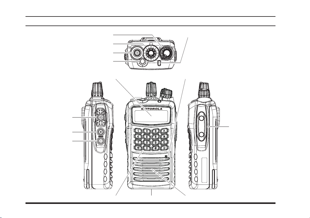
controls & connectors
(
VX-459
)
CH (Channel) Selector
LCD (Liquid Crystal Display
PTT Switch
SIDE-1 Button
SIDE-2 Button
VOL/PWR Knob
Antenna Jack
TOP SEL Key
LED Indicator (Programmable
Default settings are:
Steady Red:
Transmitting in progress
Blinking Green:
Busy Channel
Steady Green:
Tone Squelch in defeated condition
)
Microphone
SpeakerBattery Pack Latch16-Button DTMF Keypad
)
MIC/SP Jack
(
External MIC/SP
)
8
Page 11
VX-450 SerieS Operating Manual
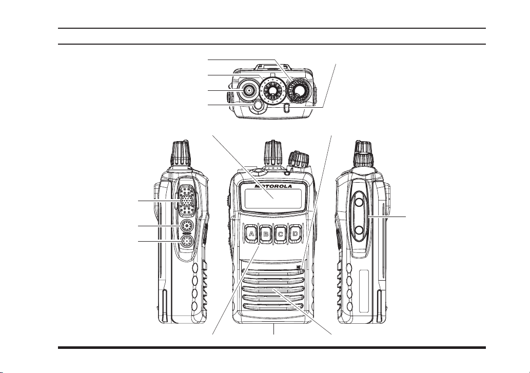
controls & connectors
(
VX-454
)
CH (Channel) Selector
LCD (Liquid Crystal Display
PTT Switch
SIDE-1 Button
SIDE-2 Button
VOL/PWR Knob
Antenna Jack
TOP SEL Key
LED Indicator (Programmable
Default settings are:
Steady Red:
Transmitting in progress
Blinking Green:
Busy Channel
Steady Green:
Tone Squelch in defeated condition
)
Microphone
SpeakerBattery Pack Latch4-Button Programmable Key
)
MIC/SP Jack
(
External MIC/SP
)
9
Page 12
VX-450 SerieS Operating Manual
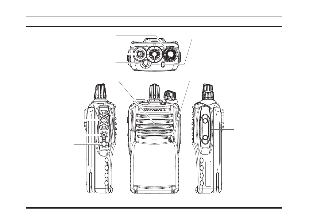
controls & connectors
(
VX-451
)
CH (Channel) Selector
PTT Switch
SIDE-1 Button
SIDE-2 Button
VOL/PWR Knob
Antenna Jack
TOP SEL Key
Speaker Microphone
Battery Pack Latch
LED Indicator (Programmable
Default settings are:
Steady Red:
Transmitting in progress
Blinking Green:
Busy Channel
Steady Green:
Tone Squelch in defeated condition
)
MIC/SP Jack
(
External MIC/SP
)
10
Page 13
VX-450 SerieS Operating Manual
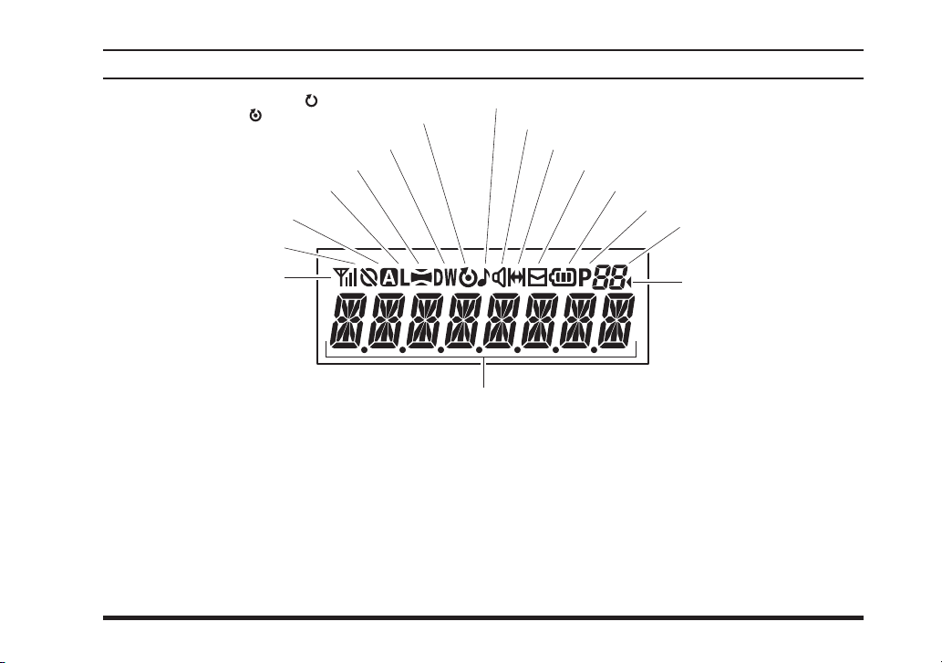
lcd Icons & IndIcators
(
VX-454 & VX-459
)
: “Priority Scan” is activated
“DUAL WATCH” is activated
“Audio Compander” is activated
Low Transmit Power Mode On
Option SW (Key Function)
or Lone Worker is activated
Encryption is activated
TX Power & RSSI Indicator
(four steps)
: “Scan” is enabled
8 Character Alpha-numeric Display
“CALL” Indicator
Receiver Monitor
“Talk-Around” is enabled
“Voice Message” is received
Battery Indicator
Priority 2 Channel
Group Number
“Group Scan” is enabled
11
Page 14
VX-450 SerieS Operating Manual
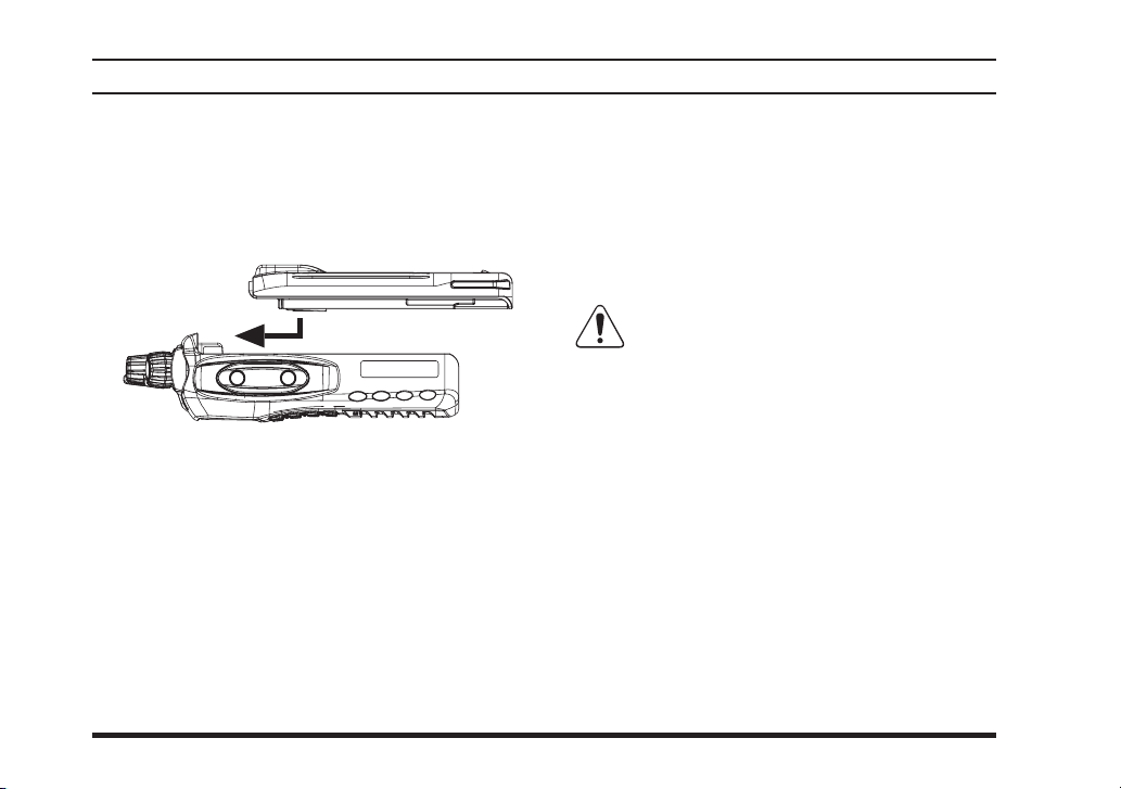
Before you BegIn
Battery Pack Installation and Removal
To install the battery pack, align the battery pack
r
to the radio with an offset about 1/2 inch (1.5 cm)
from the top edge of battery compartment, then
slide the battery pack upward until it locks in
place with a “Click.”
To remove the battery, turn the radio off and re-
r
move any protective cases. Slide the Battery Pack
Latch on the bottom of the radio toward the front
panel while sliding the battery down about 1/2
inch (1.5 cm). Then lift the battery out from the
radio.
Do n o t a t t e m p t t o open any of t h e r e charg eabl e Lithiu m-Io n pa cks, as they
could explode if accidentally short-circuited.
12
Page 15
VX-450 SerieS Operating Manual
Before you BegIn
WARNING
The IS version of the
tery Pack. To acquire the IS version of the
tion at the time of purchase. Replacement
be considered IS the radio must have originally been purchased with the IS battery option.
Do not reverse-connect the battery terminals.
¦
Do not parallel-connect the battery terminals.
¦
Do not charge batteries in hazardous locations.
¦
To reduce the risk of explosion, recharge the batteries outside of hazardous locations.
¦
VX-450
series is only intrinsically safe with the use of the
VX-450
FNB-V134LIIS-UNI
series you much select the Intrinsically Safe battery op-
batteries may also be purchased however to
FNB-V134LIIS-UNI
Bat-
13
Page 16

VX-450 SerieS Operating Manual
Before you BegIn
Battery Charging (VAC-UNI: CD-58/PA-55
Remove the Spacer Plate from the nest of the
r
optional
Spacer is installed.
Insert the DC plug from the optional
r
Adapter into the DC jack on the rear panel of the
optional
nect the
Insert the battery pack into the
r
Charger while aligning the slots of the battery
pack with the guides in the nest of the
Desktop Charger, if the Battery
CD-58
Desktop Charger, and then con-
CD-58
AC Adapter to the AC line outlet.
PA-55
CD-58
Spacer Plate
PA-55
CD-58
AC
PA-55
Desktop
CD-58
AC Line Outlet
;
)
for FNB-V133LI-UNI/-V134LI-UNI/-V134LIIS-UNI/-V136-UNI
refer to the illustration below for details on proper
positioning of the battery pack. If charging with
the transceiver attached, turn the transceiver off.
The antenna jack should be at the left side when
viewing the charger from the front.
If the battery pack is inserted correctly, the LED
r
indicator will glow red. A fully-discharged battery
pack will charge completely in 1.5 - 4.5 hours
(depending on the battery pack being charged).
When charging is completed, the LED indicator
r
will change to green.
Dis conne ct the battery pack from the
r
De s ktop C harg e r an d unp lug th e
Adapter from the AC line outlet.
1) Always use the Motorola Solutions FNB-
V133L I-UNI, FNB- V13 4LI- UNI , FNBV134LIIS-UNI Lithium-Ion Battery Pack or FNBV136-UNI Nickel-Metal Hydride Battery Pack. If the
IS version of the VX-450 is being used in a hazardous
environment where Intrinsic Safety (IS) is required
you must use the FNB-V134LIIS-UNI battery.
2) Use o n l y the Motor o l a Sol u t ions PA - 5 5 A C
Adapter.
CD-5 8
PA- 5 5
A C
14
Page 17

VX-450 SerieS Operating Manual
Before you BegIn
3) To reduce the risk of explosion, recharge the batteries outside of hazardous locations.
4) Perform the battery charging where the ambient
temperature range +41 °F to +104 °F (+5 °C to +40
°C). Charge out of this range could cause damage
to the battery pack.
5) Battery Pack shall not be exposed to excessive
heat such as sunshine, re, or the like.
6) Risk of explosion if battery is replaced by an incorrect type. Dispose of used batteries according to
the instructions
7) For further details and cautions of the charging,
refer to the Operating Manual of the CD-58 Desktop Charger.
CAUTION
Danger of explosion if battery is replaced
with an incorrect battery. Replace only with
the same or equivalent type.
Low Battery Indication
As the battery discharges during use, the voltage
gradually becomes lower. When the battery voltage
becomes to low, substitute a freshly charged battery
and recharge the depleted pack. The LED indicator
on the top of the radio will blink red when the battery
voltage is low.
15
Page 18

VX-450 SerieS Operating Manual
Before you BegIn
Belt Clip Installation and Removal
To install the Belt Clip: align the Belt Clip to
r
the groove of the Battery pack, then press the
Belt Clip downward until it locks in place with a
“Click.”
To remove the Belt Clip: use a flat head screw
r
driver to press the Belt Clip Tab away from the
battery pack to unlock the Belt Clip, then slide
the Belt Clip upward to remove it.
Belt Clip Tab
16
Page 19

VX-450 SerieS Operating Manual
Before you BegIn
MIC/SP CAP Installation
Install the
r
r
MIC/SP
Use only the supplied screws when install the
MIC/SP
This radio does not keep the submersible Rat-
ing (IP57: 1 meter / 30 minutes) when the
cap is not installed in the
SP
cap with the supplied screws.
cap.
MIC/SP
jack.
MIC/
17
Page 20

VX-450 SerieS Operating Manual
Preliminary Steps
Install a charged batt ery
r
pack onto the transceiver,
as described previously.
Screw the supplied antenna
r
onto the Antenna jack.
Never attempt to operate
this transceiver without an
antenna connected.
If you have a Speaker/Mi-
r
crophone, we recommend that it not be connected
until you are familiar with the basic operation of
the
VX-450
Water resistance of the transceiver (IP57: 1
meter / 30 minutes) is assured only when the
following conditions:
Battery pack is attached to the transceiver;
r
Antenna is connected to the antenna jack;
r
r
Series.
IMPORTANT NOTE
and
SP
MIC/SP
jack.
cap is installed in the
operatIon
MIC/
Operation Quick Start
T u rn the top pa n e l’s
r
VX-459
knob clock-
VX-454
, a channel
VOL/PWR
wi s e to t u r n the radio
on.
Turn the top panel’s CH
r
Selector knob to choose
the desired operating
channel. On the
and
name will appear on the
LCD.
If you want to select the operating channel from a
r
different Channel Group, press the Programmable
key (assigned to the Group Up or Down function)
to select the Channel Group you want before selecting the operating channel. A Group name will
appear on the LCD whenever the Programmable
key is pressed.
Note: Some models are programmed so that the
operating channels are selected by the Programmable key and the Channel Group is selected by
18
Page 21

VX-450 SerieS Operating Manual
the CH selector knob. For further details, contact
your Motorola Solutions dealer.
Rotate the
r
knob to set the volume
le v e l. If no si gn a l is
present, press and hold
in t h e
(under the
more th a n 2 s e co n d s ;
back gro und noise will
now be heard, and you
may use this to set the
VO L / P W R
the desired audio level.
Press and hold the
seconds (or press the
quiet the noise and resume normal (quiet) monitoring.
VOL/P WR
SIDE-1
PTT
kn o b fo r
b u t t o n
switch)
SIDE-1
button more than 2
SIDE-1
button twice) to
operatIon
(1) In the
The maximum number of channels is 512 (32
For example, “Channel 1” is announced as
(2) In the
The maximum number of channels is 32 (16
For example, “Channel 10” is announced as
The Channel Announcement Feature
works as described below.
VX-454/459
channels maximum per group). The radio announces the channel number digit by digit.
“one” and “Channel 10” is announced as “one
zero”.
VX-451
channels maximum per group). The radio announces Channels 1 - 9 by digit, while Channels 10 - 16 are announced by number.
“ten” and so on.
radio:
radio:
19
Page 22

VX-450 SerieS Operating Manual
To transmit, monitor the
r
channel and make sure it
is clear.
Press and hold the
swit ch. Speak into the
microphone area of the
front panel grille in a normal voice level. To return to the Receive mode, release the
Press the (Orange)
r
key to activate one
SEL
of the prep rog ram med
func t i o n s whic h ma y
have been enabled at the
time of programming by
the dealer. See the next section for details regarding the available features.
If a Speaker/Microphone
r
is available, remove the
plastic cap and its two
mounting screws from
th e ri g h t si de o f th e
transceiver, then align
th e co n n e c t o r of th e
Spe a k er/M i c rop h o n e
PTT
TOP
PTT
operatIon
switch.
on the transceiver body; secure the connector pin
using the screws supplied with the Speaker/Microphone. Hold the speaker grille up next to your
ear while receiving. To transmit, press the
switch on the Speaker/Microphone, just as you
would on the main transceiver’s body, and speak
into the microphone on a normal voice level.
Note 1): Save the original plastic cap and its
mounting screws. They should be reinstalled
when not using the Speaker/Microphone.
2) When you press the PTT switch on the Speak-
er/Microphone, it disables the internal microphone, and vice versa.
If the Busy Channel Lockout feature has been
r
prog rammed on a channel, the r adio will not
transmit when a carrier is present. Instead, the
radio will generate short beep three times and
indicate “
VX-459
the channel to be clear of activity.
CH BUSY
). Release the
” on the display (
switch and wait for
PTT
VX-454
PTT
and
20
Page 23

VX-450 SerieS Operating Manual
operatIon
If CTCSS or Digital Coded Squelch (DCS) Lock-
r
out has been programmed on a channel, the radio
can transmit only when there is no carrier being
received or when the carrier being received includes the correct CTCSS tone or DCS code.
Automatic Time-Out Timer
If the selected channel has been programmed for automatic time-out, you must limit the length of each
transmission. While transmitting, a beep will sound
10 seconds before time-out. Another beep will sound
just before the deadline; the top panel’s red LED (“TX”
indicator) will disappear and transmission will cease
soon thereafter. To resume transmitting, you must release the
to expire.
switch and wait for the “penalty timer”
PTT
adVanced operatIon
Programmable Key Functions
All versions of the
, and
SIDE-1
include the
thermore, the
tion keys.
The Programmable key functions can be customized,
via programming by your Motorola Solutions dealer,
to meet your communications/network requirements.
Some features may require the purchase and installation of optional internal accessories. The possible
Prog ram mable key progra mmi ng f eatures are i llustrated on the next page, and their functions are
explained beginning after page 22 For further details,
contact your Motorola Solutions dealer.
For future reference, check the box next to each function that has been assigned to the Programmable key
on your particular radio, and keep it handy.
[A], [B], [C]
VX-450
SIDE-2
VX-459
include the
key. The
includes the []
, and
VX-454
[D]
function keys. Fur-
TOP SEL
and
VX-459
[#]
and
func-
,
21
Page 24

VX-450 SerieS Operating Manual
adVanced operatIon
functIon
None / / / / / / / / /
Monitor / / / / / / / / /
Monitor -Momentarily- /--- /--- /--- /--- /--- /--- /--- /--- /--Lamp / / / / / / / / /
Low Power / / / / / / / / /
Encryption / / / / / / / / /
Set / / / / / / / / /
SQL OFF / / / / / / / / /
SQL OFF -Momentarily- / / / / / / / / /
ø
1
SQL Set
Beep Off / / / / / / / / /
Whisper / / / / / / / / /
VOX / / / / / / / / /
ø
1
VOX Set
Clear Voice / / / / / / / / /
AF Min Volume / / / / / / / / /
Emergency /--- /--- /--- /--- /--- /--- /--- /--- /--CH Announcement / / / / / / / / /
VOX Anti-Trip / / / / / / / / /
Lone Worker / / / / / / / / /
ø
1
Group Up
Group Down
Channel Up
Channel Down
Speed Channel Up
Speed Channel Down
RPI-1 / / / / / / / / /
PRI-2 / / / / / / / / /
PRI-2 Set / / / / / / / / /
PRI-2 Disable / / / / / / / / /
Direct Channel 1
Direct Channel 2
Direct Channel 3
Direct Channel 4
Direct Channel Entry
ø
1
ø
1
ø
1
ø
ø
ø
ø
TOP SEL SIDE-1 SIDE-2
/ / / / / / / / /
/ / / / / / / / /
/ / / / / / / / /
/ / / / / / / / /
/ / / / / / / / /
ø
1
1
1
1
1
ø
/ / / / / / / / /
---/ ---/ ---/ ---/ ---/ ---/ ---/ ---/ ---/
ø
1
---/ ---/ ---/ ---/ ---/ ---/ ---/ ---/ ---/
/ / / / / / / / /
/ / / / / / / / /
/ / / / / / / / /
/ / / / / / / / /
2
/ / / / / / / / /
programmaBle Key (press Key / press and hold Key)
[A]
ø
1
[B]
ø
1
[C]
ø
1
[D]
ø
1
[Ü]
ø
2
[#]
ø
2
22
Page 25

VX-450 SerieS Operating Manual
adVanced operatIon
functIon
Scan / / / / / / / / /
Group Scan / / / / / / / / /
Dual Watch / / / / / / / / /
FM Scan / / / / / / / / /
ø
1
Scan Set
Group Scan Set
TA Scan / / / / / / / / /
Talk Around / / / / / / / / /
Reset / / / / / / / / /
Call 1 / / / / / / / / /
Call 2 / / / / / / / / /
Call 3 / / / / / / / / /
Call 4 / / / / / / / / /
Call 5 / / / / / / / / /
Code Up
Code Down
Code Set
Speed Dial
DTMF Code Set
Call / / / / / / / / /
Status Set
Status Up
Status Down
Status Check
Duty / / / / / / / / /
ID Check
ARTS Login
Option Switch 1 /--- /--- /--- /--- /--- /--- /--- /--- /--Option Switch 2 / / / / / / / / /
ø
REC
PLAY
TX Save Disable / / / / / / / / /
Lock / / / / / / / / /
ø
1: VX-454 and VX-459 only.
ø
2: VX-459 only
ø
3: DVS-9 is required.
ø
1
ø
1
ø
1
ø
1
ø
1
ø
2
ø
1
ø
1
ø
1
ø
1
ø
1
ø
1
3
ø
3
.
TOP SEL SIDE-1 SIDE-2
/ / / / / / / / /
/ / / / / / / / /
/ / / / / / / / /
/ / / / / / / / /
/ / / / / / / / /
/ / / / / / / / /
/ / / / / / / / /
/ / / / / / / / /
/ / / / / / / / /
/ / / / / / / / /
/ / / / / / / / /
/ / / / / / / / /
/ / / / / / / / /
/ / / / / / / / /
/ / / / / / / / /
programmaBle Key (press Key / press and hold Key)
[A]
ø
1
[B]
ø
1
[C]
ø
1
[D]
ø
1
[Ü]
ø
2
[#]
ø
2
23
Page 26

VX-450 SerieS Operating Manual
adVanced operatIon
Description of Operating Functions
monItor
Press (or press and hold) the assigned Programmable
key to cancel any signaling features; the
indicator will glow green.
monItor -momentarIly-
Cancel any signaling features while pressing the assigned programmable key.
(
lamp
VX-454 & VX-459 only
Press (or press and hold) the assigned Programmable
key to illuminate the display for ve seconds.
)
low power
Press (or press and hold) the assigned Programmable
key to set the radio’s transmitter to the “Low Power”
mode, thus extending battery life. Press (or press and
hold) the key again to return to “Normal” transmit
power when in difcult terrain.
In the
VX-454/-459
set to “Low Power” mode, the “L” icon will be indicated on the display.
, when the radio’s transmitter is
BUSY/TX
encryptIon
Press (or press and hold) the assigned Programmable
key to toggle the Encryption feature “On” and “Off.”
In the
VX-454/-459
ture is activated, the “
the display.
Important Note: The Voice Scrambler feature is not
activated, when the optional
with Digital Voice Storage Unit is installed.
(
set
VX-454 & VX-459 only
Press (or press and hold) the assigned Programmable
key to activate the “User Set” (Menu) Mode. See
“User Set Mode” chapter for details.
, when the Voice Scrambler fea-
” icon will be indicated on
Man Down Alert
DVS-9
)
sQl off
Press (or press and hold) the assigned programmable
key to open the SQL to hear background noise (unmute
the audio).
sQl off -momentarIly-
Opens the SQL to hear background noise (unmute the
audio) while pressing the assigned programmable key.
24
Page 27

VX-450 SerieS Operating Manual
adVanced operatIon
sQl set
You can manually adjust the squelch level using this
function:
Press (or press and hold) the assigned Program-
r
mable key. A tone will sound, and the current
squelch level will appear on the display.
Press the
r
ton to select the desired squelch level.
Press the
r
display indicates “
the normal channel indication.
You may cancel the new setting by pressing the
key. In this case, the display indicates “
briey.
(
VX-454 & VX-459 only
SIDE-1/SIDE-2
[D]
key to store the new setting. The
- SET -
Beep off
Press (or press and hold) the assigned Programmable
key to disable the radio beeps temporarily. Again
press (or press and hold) the assigned Programmable
key to enable the radio beeps.
)
button or
” briey, then reverts to
[A]/[B]
but-
- CANCEL -
[C]
whIsper
Press (or press and hold) the assigned Programmable
key to increase the microphone gain; thus you can
speak in a low voice (whisper) temporarily. Again
press (or press and hold) the assigned Programmable
key to resume normal microphone gain.
VoX
Press (or press and hold) the assigned programmable
key to turn the VOX function “On” or “Off”. You
may disable the VOX function temporarily by pressing the
”
PTT
switch.
25
Page 28

VX-450 SerieS Operating Manual
adVanced operatIon
VoX set
You can manually adjust the VOX Gain using this
function:
Press (or press and hold) the assigned program-
r
mable key. A tone will sound, and the current
VOX Gain level will appear on the display.
Press the
r
VOX Gain level.
Press the
r
display indicates “
the normal channel indication.
You may cancel the new setting by pressing the
key. In this case, the display indicates “
briey.
(
VX-454 & VX-459 only
[A]/[B]
[D]
button to select the desired
key to store the new setting. The
- SET -
clear VoIce
Press (or press and hold) the assigned programmable
key to activate the Clear Voice feature. When you are
operating in a noisy environment, activate the Clear
Voice feature. Again press (or press and hold) the assigned programmable key to disable the Clear Voice
feature.
)
” briey, then reverts to
[C]
- CANCEL -
af mIn Volume
Press (or press and hold) the assigned Programmable
key to reduce the audio output to the (lower) level
programmed by your Motorola Solutions dealer.
ch announcement
Press (or press and hold) the assigned Programmable
key to select the channel change confirmation between “beep” and “announcement”.
VoX antI-trIp
Press (or press and hold) the assigned Programmable
key to toggle the VOX Anti-Trip feature “On” and
”
“Off”.
When the VOX Anti-Trip feature is set to “On”, the
transceiver does not activate the transmitter section
from the receiver audio and own beep sound.
In the
VX-454/-459
ture is set to “On”, the display indicates “
briefly. When the VOX Anti-Trip feature is set to
“Off”, the display indicates “
, when the VOX Anti-Trip fea-
ATRP ON
ATRP OFF
” briey.
”
26
Page 29

VX-450 SerieS Operating Manual
adVanced operatIon
emergency
The
VX-450
which may be useful for alerting another party monitoring on the same frequency as your transceiver’s
channel.
Press the assigned Programmable key to initiate an
emergency call. For further details contact your Motorola Solutions dealer.
lone worKer
Press (or press and hold) the assigned Programmable
key to toggle the Lone Worker feature “On” and “Off”.
The Lone Worker feature is designed to emit an alarm
for 30 seconds when the Lone Worker Timer (programmed by your Motorola Solutions dealer) has expired. If the user does not reset the timer by pressing
the
PTT
mode.
In the
is activated, the “
display.
series include an “Emergency” feature
switch, the radio switches to the Emergency
VX-454/-459
, when the Lone Worker feature
” icon will be indicated on the
group up/down
(
VX-454 & VX-459 only
)
Press (or press and hold) the assigned Programmable
key to select a different Group of channels. Once
the desired Group is reached, rotate the CH Selector
knob to select the desired channel within the selected
Group.
channel up/down
(
VX-454 & VX-459 only
)
Press (or press and hold) the assigned Programmable
key to select a different channel within the current
Group.
speed ch up/down
(
VX-454 & VX-459 only
)
Press and hold the assigned programmable key causes
the radio to begin stepping (repeatedly) upward or
downward through the channels.
prI-1/prI-2
Press (or press and hold) the assigned programmable
key to recall the pre-programmed priority channel
directly. This is pre-programmed by your Motorola
Solutions dealer.
27
Page 30

VX-450 SerieS Operating Manual
adVanced operatIon
prI-2 set
Press (or press and hold) the assigned programmable
key to toggle the current channel to the priority channel 2 “enable” and “disable”.
prI-2 dIsaBle
Press (or press and hold) the assigned programmable
key to disable the priority channel 2 of the group temporarily.
dIrect ch1 to ch4
Press (or press and hold) the assigned Programmable
key to recall the Dealer pre-programmed channel directly.
(
VX-454 & VX-459 only
)
dIrect ch entry
You can recall the desired channel directly using this
function:
Press (or press and hold) the assigned program-
r
mable key. A tone will sound, and the current
group/channel number will appear on the display.
Enter the desired group number (two digits) and
r
channel number (two digits) by the keypad.
Press the
r
display indicates “
the normal channel indication.
You may cancel the new setting by pressing the
key. In this case, the display indicates “
briey.
[D]
(
VX-459 only
key to store the new setting. The
- SET -
)
” briey, then reverts to
[C]
- CANCEL -
”
28
Page 31

VX-450 SerieS Operating Manual
adVanced operatIon
scan
The Scanning feature is used to monitor multiple
signals programmed into the transceiver. While scanning, the transceiver will check each channel for the
presence of a signal, and will stop on a channel if a
signal is present.
To activate scanning:
Press (or press and hold) the assigned Program-
r
mable key to activate scanning.
The scanner will search the channels of each
r
channel, looking for active ones; it will pause
each time it nds a channel on which someone is
speaking.
Press (or press and hold) the assigned Program-
r
mable key again to disable scanning. Operation
will revert to the programmed revert channel.
Note: Your dealer may have programmed your radio
to stay on one of the following channels if you press
the
switch during scanning pause:
PTT
“Scan Pause” channel (“Talk Back”)
“Last Busy” channel
“Priority-1/-2” channel
“User Programmed” channel (“Select Channel”)
“Scan Start” channel
group scan
The Scanning feature is used to monitor multiple
channels programmed into the transceiver. While
scanning, the transceiver will check each channel of
the programmed group for the presence of the signal,
and will stop on a channel if a signal is present.
Press (or press and hold) the assigned programmable
key to activate the scanning on the selected groups.
29
Page 32

VX-450 SerieS Operating Manual
adVanced operatIon
dual watch
The Dual Watch feature is similar to the SCAN feature, except that only two channels are monitored:
The current operating channel; and
The Priority-1/-2 channel.
To activate Dual Watch:
Press (or press and hold) the assigned Program-
r
mable key.
The scanner will search the two channels; it will
r
pause each time it nds a channel on which someone is speaking.
To stop Dual Watch:
Press (or press and hold) the assigned Program-
r
mable key.
Operation will revert to the “Dual Watch Revert”
r
channel.
fm scan (follow-me scan
The FM Scan feature checks a User-assigned Priority
Channel regularly as you scan other channels. Thus,
if only Channels 1, 3, and 5 (of the 8 available channels) are designated for “Scanning,” the user may
nonetheless assign Channel 2 as the “User-assigned”
Priority Channel via the FM Scan.
To activate FM Scan, rst select the channel you want
to designate as the “User-Assigned Priority Channel”
and press (or press and hold) the assigned programmable key. Then rotate the CH Selector knob to recall to the “Scanning Start” channel which has been
programmed by your dealer to activate the scanner.
When the scanner stops on an “Active” channel, the
User-assigned Priority Channel will automatically be
checked every few seconds; if activity is found on the
User-assigned Priority Channel, the radio will switch
between it and the Dealer-Assigned Priority Channel,
if any.
)
30
Page 33

VX-450 SerieS Operating Manual
adVanced operatIon
scan set
(
VX-454 & VX-459 only
Press (or press and hold) the assigned programmable
key to add/delete the current channel to/from your
scanning list.
Wh en yo u de l ete c h anne l , th e dis play ind i cates
“
SCN SKIP
” briey and the “
from the display. To restore a particular channel to
your scanning list, press (or press and hold) the assigned programmable key again; the display indicates
“
SCN SET
” briey and “
display.
Furthermore, press (or press and hold) the assigned
programmable key while the scanner is paused, this
removes the channel from the scan list temporarily.
group scan set
(
VX-454 & VX-459 only
You may wish to have the Scanner pass through more
than one Group during the scanning process (normally,
scanning is performed within the current group only).
To include the current Group in the scanning loop,
press (or press and hold) the assigned programmable
key (the “” icon will appear on the display). To
remove a current Group from Group Scan, press (or
press and hold) the assigned programmable key again
(the “” icon will disappear from the display).
)
” icon will disappear
” icon will appear on the
)
ta scan
Press (or press and hold) the assigned Programmable
key to toggle the TA (Talk Around) scan feature “On”
and “Off.”
While TA scan is proceeding, the transceiver will
search both the transmit and receive frequencies (In
the
VX-454/-459
a signal is encountered on the receive frequency, the
VX-450
will pause until the signal disappears (“
icon will appear but not blink). When a signal is encountered on the transmit frequency, the transceiver
will check for activity on the receive frequency every
few seconds (interval programmed by your Motorola
Solutions dealer.).
Note: The TA Scan feature does not activate on the
Simplex Channel.
, the “
” icon will blink). When
”
31
Page 34

VX-450 SerieS Operating Manual
adVanced operatIon
talK around
Press (or press and hold) the assigned Programmable
key to activate the Talk Around feature when you are
operating on duplex channel systems (separate receive and transmit frequencies, utilizing a “repeater”
station). The Talk Around feature allows you to bypass the repeater station and talk directly to a station
that is nearby. This feature has no effect when you are
operating on “simplex” channels, where the receive
and transmit frequencies are already the same.
In the
VX-454/-459
vated, the “
Note that your dealer may have mode provision for
“Talk Around” channels by programming “repeater”
and “Talk Around” frequencies on two adjacent channels. If so, the key may be used for one of the other
Pre-Programmed Functions.
Note: The Talk Around feature does not activate on
the Simplex Channel.
(ta)
, when the “TA” function is acti-
” icon will be indicated on the display.
reset
Press (or press and hold) the assigned programmable
key to reset the RFC (Ready for Communication)
condition.
call 1 to call 5
Press (or press and hold) the assigned Programmable
key to send a 2-tone/5-tone sequential tone group
which is pre-dened.
code up/down
Press (or press and hold) the assigned Programmable
key to select a 2-tone/5-tone encode code from the
pre-dened encode list.
(
VX-454 & VX-459 only
)
32
Page 35

VX-450 SerieS Operating Manual
adVanced operatIon
code set
Press (or press and hold) the assigned program-
r
(
VX-454 & VX-459 only
mable key to change the 5-Tone encoding digit.
To change the tones, select the desired digit using
[A]/[B]
the
the
Press the
r
display indicates “
keys, then change the number using
SIDE-1/SIDE-2
[D]
keys.
key to store the new setting. The
- SET -
the normal channel indication.
You may cancel the new setting by pressing the
key. In this case, the display indicates “
briey.
In the
VX-459
, you may enter the 5-Tone encoding
code directly from the 16-Button DTMF keypad (
- [9]
) and
[]
key (wild card).
)
” briey, then reverts to
- CANCEL -
[C]
[0]
speed dIal
(
VX-454 & VX-459 only
)
Your Dealer may have pre-programmed Auto-Dial
telephone number memories into your radio.
To dial a number, press the
[A]/[B]
key to select the
Auto-Dial memory number list provided by your
Dealer or Network Administrator, then press the
PTT
switch. The DTMF tones sent during the dialing sequence will be heard in the speaker.
In the
”
VX-459
Programmable key, then press the front panel’s nu-
, press (or press and hold) the assigned
meric key corresponding to the Auto-Dial memory
number list provided by your Dealer or Network Administrator. The DTMF tones sent during the dialing
sequence will be heard in the speaker.
33
Page 36

VX-450 SerieS Operating Manual
adVanced operatIon
dtmf code set
You may send the desired telephone number manually.
To dial a number manually, press (or press and hold)
the assigned Programmable key, then press the desired numbers on the front panel’s numeric key. Now,
press the
The DTMF tones sent during the dialing sequence
will be heard in the speaker.
PTT
(
VX-459 only
switch to send the telephone number.
call
When using the DTMF Paging System
This feature, if enabled, allows the user to change the
3-digit Page Call code, used to call other similarlyequipped stations. Press (or press and hold) the assigned programmable key, followed by the three digits
representing the Page Call code of the station you wish
to call. Three tones will be heard after the last key is
pressed (the new code will now be transmitted).
The receiv er squelc h of the o ther statio n will be
opened, and you can begin communication.
)
When using the 2-tone/5-tone Signaling System
This feature, if enabled, press (or press and hold) the
assigned programmable key to send a 2-tone/5-tone
sequential tone.
When using the MDC1200 System
This feature, if enabled, press (or press and hold) the
assigned programmable key to send an MDC1200
code.
Press (or press and hold) the assigned program-
r
mable key to enter the “Call Menu” mode.
Press the
r
Call mode, then press the
selection. You may cancel the selection by pressing the
Press the
r
be called.
You may enter the station’s ID number (four dig-
its) directly from the 16-Button DTMF keypad
[0] - [9], [A]
(
[]
Press the
r
SIDE-1/SIDE-2
[C]
key.
SIDE-1/SIDE-2
[D], [#]
-
: wild card), if your transceiver is
switch to send an MDC1200 call.
PTT
to select the desired
[D]
key to accept the
to select the station to
: substitute for “E”, and
.
VX-459
34
Page 37

VX-450 SerieS Operating Manual
adVanced operatIon
status set
(
VX-454 & VX-459 only
Press (or press and hold) the assigned Programmable
key to change the 5-Tone status code. To change the
status code, select the desired digit by
change the number by
number by
[D]
key.
status up/down
[B]/[C]
(
VX-454 & VX-459 only
Press (or press and hold) the assigned Programmable
key to se lec t a 5-Tone stat us code from the p redened status list.
status checK
(
VX-454 & VX-459 only
Press (or press and hold) the assigned Programmable
key to check the 5-Tone receive status code. When
you press (or press and hold) this key, the display will
indicate the “Message” corresponding to the receive
status condition per the pre-dened status list.
)
[A]
key, then
key, and store the
)
)
duty
Press (or press and hold) the assigned Programmable
key to toggle the Duty function of the 2-tone/5-tone
decoder “On” and “Off.”
When the Duty function is set to “On,” the user will
always hear (depending on the sub-audio signalling)
all trafc on the paging channel. The radio will sound
the paging alert when it receives the programmed
2-tone/5-tone code.
When t he Duty func tio n is set to“O ff, ” the user
wi ll NOT hea r nor mal ra dio tr a ffic o n the p aging channel. The radio will sound the paging alert
and unmute only when it receives the programmed
2-tone/5-tone code.
35
Page 38

VX-450 SerieS Operating Manual
adVanced operatIon
Id checK
(
VX-454 & VX-459 only
This function allows logged ID of the DTMF Signaling and 5-tone Signaling to be reviewed and relayed
(5-tone Signaling only) to a specic station:
Press (or press and hold) the assigned program-
r
mable key to display the logged ID of the DTMF
Signaling and 5-tone Signaling.
r
Press the
[A]
key to select the category (“DTMF
Signaling” or “5-tone Signaling”) to be reviewed,
then press the
SIDE-1/SIDE-2
ID.
Press the
r
[B]
key to toggle the display between
the “ID code display” and “Tag display”.
Press the
r
[D]
key to send the Call back, when
recalling the ID of the “5-tone Signaling”, if desired.
You may cancel the Call back sending by press-
[C]
ing the
“
- CANCEL -
key. In this case, the display indicates
” briey.
)
keys to select the
arts logIn
(
VX-454 & VX-459 only
)
This function enable the displaying the logged ID of
the MDC1200 ARTS
Press (or press and hold) the assigned program-
r
TM
(ARTSTMII).
mable key to display the number of the logged
station of the MDC1200 ARTS
r
Press the
SIDE-1/SIDE-2
TM
(ARTSTMII).
keys to display the ID.
optIon swItch 1
Activates the optional accessory “1” while pressing
the assigned Programmable key.
optIon swItch 2
Press (or press and hold) the assigned Programmable
key to toggle the optional accessory “2” “On” and
“Off.”
:
VX-454
)
” stays onø.
and
” Icon will
VX-459
Only.
rec
(reQuIres the dVs-8 or dVs-9
Press (or pres s an d hold) the assigned Programmable key to enable the Voice Recording Mode. If
the incoming signal is received, so as to un-mute
the squelch and pass audio, then the “
ashø and received audio will be recorded. When the
voice recording is completed, the “
ø
36
Page 39

VX-450 SerieS Operating Manual
adVanced operatIon
play
(reQuIres the dVs-8 or dVs-9
Press (or press and hold) the assigned programmable
key to play back the last message.
Press (or press and hold) the assigned programmable
key again to stop the play-back.
While playback is proceeding, you may press the
key to jump to the previous message, or press the
key to jump to the next message. Furthermore, press
[D]
the
key to delete all messages and stop the play-
back.
tX saVe dIsaBle
Press (or press and hold) the assigned Programmable
key to disable the Transmit Battery Saver, if you are
operating in a location where high power is almost
always needed.
The Transmit Battery Saver helps extend battery life
by reducing transmit power when a very strong signal
from an apparently nearby station is being received.
Under some circumstances, though, your hand-held
radio may not be heard well at the other end of the
communication path, and high power may be necessary at all times.
)
[A]
[B]
locK
Press (or press and hold) the assigned Programmable
key to lock the CH Selector knob, Programmable
keys, and
lation is programmed by your Motorola Solutions
Dealer.
switch. The precise lockout congu-
PTT
37
Page 40

VX-450 SerieS Operating Manual
locK
In order to prevent accidental channel chang e or
inadv ertent t ransmis sion, vario us aspec ts o f th e
Selector knob, Programmable keys, and
CH
switch may be locked.
The precise lockout conguration is programmed by
your Dealer.
To locked out the key locking, turn the radio off.
Now, press and hold the
turning the radio on again.
To cancel locking, repeat this process.
PTT
and
SIDE-2
PTT
key while
man down functIon
(
reQuIres the dVs-9
The man down function is programmable to monitor
a variety of worker timed safety scenarios vertically
and horizontally as well as worker degree of motion.
For further details contact your Motorola Solutions
Dealer.
)
tm
(
arts
This system is designed to inform you when you and
another ARTS
nication range.
During ARTS
an incoming ARTS
and “
IN SERV
display for 2 seconds
more than two minutes, your radio senses that no signal has been received; a short triple-beep will sound,
and “
OUT SERV
on the display for 2 seconds
move back into communication range, as soon as the
other station transmits, a short beep will sound and
“
IN SERV
2 seconds
” will be indicated again on the display for
ø
auto range transpond system
TM
-equipped station are within commu-
TM
operation, when the radio receives
TM
signal, a short beep will sound,
” (“In Service”) will be indicated on the
ø
. If you move out of range for
” (“Out of Service”) will be displayed
ø
:
VX-454
ø
. If you subsequently
and
VX-459
)
Only.
38
Page 41

VX-450 SerieS Operating Manual
user set mode
The
VX-454/-459
Mode which allows the user to define or configure
various settings, such as Beep On/Off, Squelch, etc.
To activate the “User Set (Menu)” Mode:
Press (or press and hold) the programmable key
r
assigned to the “
S e l e ct the U s e r Set Mo d e Item y o u wish to
r
ch ange u sing the
[
SIDE-1]/[SIDE-2
the selected item.
Press the
r
The display indicates “
to normal operation.
You may cancel the selection by pressing the
key. The display indicates “
then exits to normal operation.
Note: The menu “14: REC Mode” and “15: Play
Mode” will appear only when the Voice Recording Unit is installed.
includes a “User Set ( Menu)”
” function.
SET
[A]/[B]
]
button to adjust the setting of
[D]
key to store the new conguration.
keys, the n use the
” briey, then exits
- SET -
- CANCEL -
” briey,
[C]
dIsplay descrIptIon
1 SQL
2 BEEP
3 BELL
4 LIGHT
5 KEY
6 DIAL
7 PTT
8 SCAN
9 DW
10 AF
11 VOX
12 TX SV
13 ENCR
14 REC
15 PLY
Select the Squelch Threshold Level (–15 to +15)
Set the Beep ON / OFF
Set the Bell ON / OFF
(Bell engaged by sub-audible CTCSS/DCS)
Set the BUSY/TX LED and Lamp ON / OFF
Set the Key Lock function ON (Lock) / OFF (Free)
Set the DIAL Lock function ON (Lock) / OFF (Free)
Set the PTT Lock function ON (Lock) / OFF (Free)
Set the Scan status
OFF: Stop the Scan
ON: Start the Scan
GRP: Start the Group Scan
FM: Start the Follow-Me Scan
Set the Dual Watch ON / OFF
(same function as DW key)
Set the Minimum Volume level (000 to 255)
Set the VOX level (–2 to +2)
(This menu will appear only when the VOX setting
of the current channel is set to “Key ON” or “Power
ON”)
Set the TX Saver ON / OFF
Set the Encryption ON / OFF
(This menu will appear only when the Encryption setting of the current channel is set to “Key ON” or “Power
ON”)
Select the recording mode.
ONE: Enables recording one mes sag e (m ax. 120
seconds), and playback from the beginning of
the message.
ROL: Enables recording whenever squelch opens,
and playback of the last 120 seconds.
Set the priority audio on playback mode.
PLY: Playback audio is higher priority than received
signal.
SIG: Rec eive d sig nal is h ighe r priority than play-
back audio.
39
Page 42

VX-450 SerieS Operating Manual
optIonal accessorIes
Is approVed accessorIes
FNB-V134LIIS-UNI
Submersible Speaker Microphone
A4B
MH-66
VH-150A
VH-150B
DVS-9
FVP-44
ATV-16A
ATV-16B
ATV-16C
ATV-16XL
ATU-16B
ATU-16C
ATU-16D
ATU-16F
CSS-450
CLIP-20
ø
Behind Type VOX Compatible Microphone
Over the Head VOX Compatible Microphone
Man Down Alert with Digital Voice Storage Unit
VHF Antenna (136-150 MHz)
VHF Antenna (150-162 MHz)
VHF Antenna (162-174 MHz)
VHF Antenna (Untuned)
UHF Antenna (400-420 MHz)
UHF Antenna (420-450 MHz)
UHF Antenna (450-470 MHz)
UHF Antenna (470-520 MHz)
Channel Selector Stopper
Belt Clip
:
When the
Voice Storage Unit is installed, the Voice Scrambler feature is not activated.
7.4V
ANI & Encryption Unit
Man Down Alert with Digital
DVS-9
, 2300 mAh Li-Ion Battery Pack
IMPORTANT NOTE
If any of the IS Exempt Accessories are used
with the IS version of the
radio is no longer considered intrinsically safe
and must not be used in hazardous locations.
VX-450
series, the
40
Page 43

VX-450 SerieS Operating Manual
optIonal accessorIes
Is eXempt accessorIes
FNB-V133LI-UNI
FNB-V134LI-UNI
FNB-V136-UNI
Desktop Charger for FNB-V133LI-UNI/-V134LI-UNI/-V134LIIS-UNI/-V136-UNI
CD-58
PA-55
VAC-UNI
VAC-6058
VCM-5
MH-100
MH-101
MH-102
MH-37
MH-45
MH-360S
MH-450S
LCC-133/134
CE115
FIF-12
CT-106
CT-27
(CD-58+PA-55)
A4B
A4B
A4B-1
B4B
PC Programming Software
USB Programming Interface
Programming Cable for FIF-12
Radio to Radio Cloning Cable
7.4V
7.4V
7.2V
AC Adapter for CD-58
Desktop Charger for FNB-V133LI-UNI/-V134LI-UNI/-V134LIIS-UNI/-V136-UNI
6-Unit Multi Charger for FNB-V133LI-UNI/-V134LI-UNI/-V134LIIS-UNI/-V136-UNI
Vehicular Charger Mounting Adapter for CD-58
Receive Only Earpiece (for MH-45
Earpiece Microphone
1 Wire Surveillance Kit
2 Wire Surveillance Kit
Noise Cancelling Speaker Microphone
Compact Speaker Microphone
Speaker Microphone
Leather Case
, 1380 mAh Li-Ion Battery Pack
, 2300 mAh Li-Ion Battery Pack
, 1200 mAh Ni-MH Battery Pack
B4B
/-360S/-450S)
If any of the IS Exempt Accessories are used
with the IS version of the
radio is no longer considered intrinsically safe
and must not be used in hazardous locations.
Availability of accessories may vary; some
accessories are supplied standard per local
requirements, others may be unavailable in
some regions. Check with your Motorola Solutions Dealer for changes to this list.
IMPORTANT NOTE
VX-450
series, the
41
Page 44

VX-450 SerieS Operating Manual
warranty polIcy
Motorola Solutions warrants, to the original purchaser only, its Motorola Solutions manufactured communications
products against defects in materials and workmanship under normal use and service for a given period of time
from the date of purchase.
Limited Warranty Details:
contact the authorized Motorola Solutions dealer in your country.
Part 15.21: Changes or modications to this device not expressly approved by Motorola Solutions could
void the user’s authorization to operate this device.
42
Page 45

VX-450 SerieS Operating Manual
note
43
Page 46

note
VX-450 SerieS Operating Manual44
Page 47

Disposal of your ElEctronic anD ElEctric EquipmEnt
Products with the symbol (crossed-out wheeled bin) cannot be disposed as household waste.
Electronic and Electric Equipment should be recycled at a facility capable of handling these
items and their waste by products.
In EU countries, please contact your local equipment supplier representative or service center
for information about the waste collection system in your country.
attEntion in casE of usE
This transceiver works on frequencies which are not generally permitted.
For frequency allocation, apply for a licence at your local spectrum management authority.
For actual usage contact your dealer or sales shop in order to get your
transceiver adjusted to the allocated frequency range.
List of the practicable area
AUT BEL BGR CYP CZE DEU DNK
ESP EST FIN FRA GBR GRC HUN
IRL ITA LTU LUX LVA MLT NLD
POL PRT ROU SVK SVN SWE CHE
ISL LIE NOR
Page 48

MOTOROLA, MOTO, MOTOROLA SOLUTIONS and Stylized M logo are trademarks or registered trademarks of Motorola Trademark Holdings, LLC and are used under license.
All other trademarks are the property of their respective owners.
©2017 Motorola Solutions, Inc.
All rights reserved.
Motorola Solutions, Inc.
500 W. Monroe Street Chicago, IL 60661 USA
 Loading...