

Page 1
VX-261
oPerating manual
Programmable Functions/Features
IP55 Water Resistant
Two Programmable Function Keys
2-Tone Encode/Decode
5-Tone Encode/Decode
MDC-1200® Encode (ANI Encode
DTMF Encode
Scan
Dual Watch
Follow-Me Scan
Talk Around Scan
VOX
Talk Around
Emergency
Lone Worker
TX Save Disable
Lock
ARTS™
(
Auto Range Transpond System
)
)
Page 2

contents
Introduction ..................................................................... 1
Important Safety Information ....................................... 2
Consignes de sécurité importantes ................................ 4
Before You Begin ............................................................. 6
Battery Pack Installation and Removal ....................... 6
Battery Charging ......................................................... 6
Low Battery Indication ................................................7
Belt Clip Installation and Removal ............................. 8
MIC/SP Cap Installation .............................................8
Controls & Connectors ................................................... 9
Congratulations!
You now have at your ngertips a valuable communications tool, a Motorola Solutions two-way radio! Rugged, reliable and
easy to use, your Motorola Solutions radio will keep you in constant touch with your colleagues for years to come, with neg-
ligible maintenance down-time. Please take a few minutes to read this manual carefully. The information presented here will
allow you to derive maximum performance from your radio, in case questions arise later on.
Important Note
There are no owner-serviceable parts inside the radio. All service jobs must be referred to an authorized Motorola
r
Solutions Service Representative.
In order to maintain the specied water integrity performance, periodic maintenance is recommended.
r
Should the radio sustain a severe shock (e.g. if it is dropped), the water integrity may be compromised, requiring
r
service. Should this occur, contact your Authorized Motorola Solutions Dealer.
Operation ....................................................................... 10
Preliminary Steps ......................................................10
Operation Quick Start ................................................10
Automatic Time-Out Timer ....................................... 12
Advanced Operation ..................................................... 13
Programmable Key Functions .................................. 13
Description of Operating Functions ......................... 14
Lock ................................................................................ 19
ARTS™ (Auto Range Transpond System) ................. 19
Optional Accessories ..................................................... 20
Page 3

introduction
The
VX-261
Mobile bands. This transceiver is designed for reliable business communications in a wide variety of applications with a
wide range of operating capability provided by their leading-edge design, and allows up to 16-channel capacity.
Important channel frequency data is stored in the ash memory, and is easily programmable by a Motorola Solutions licensed dealers using a personal computer with Motorola Solutions Programming equipment:
Interface, and
cloning cable
is full-featured Hand-Held Analog Transceiver designed for business communications in the VHF/UHF Land
USB Programming
FIF-12
CT-106
CT-27
Connection cable with
can be used to program additional radios directly.
CE150
PC Programming Software. Or, once a single radio is programmed,
This manual will describe the details of the many advanced features of the
wish to consult with your Network Administrator regarding precise details of the conguration of this equipment for use in
your application.
VX-261
. After reading this manual, you may
Important Notice for North American Users Regarding 406 MHz Guard Band
The U.S. Coast Guard and National Oceanographic and Atmospheric Administration have requested the cooperation
of the U.S. Federal Communications Commission in preserving the integrity of the protected frequency range 406.0
to 406.1 MHz, which is reserved for use by distress beacons. Do not attempt to program this apparatus, under any
circumstances, for operation in the frequency range 406.0 - 406.1 MHz if the apparatus is to be used in or near North
America.
Warning - Frequency band 406 - 406.1 MHz is reserved for use ONLY as a distress beacon by the US Coast Guard
and NOAA. Under no circumstance should this frequency band be part of the pre programmed operating frequencies
of this radio.
VX-261 Operating Manual 1
Page 4

VX-261 Operating Manual
imPortant saFety inFormation
english
ATTENTION!
This radio is restricted to Occupational use only. Before using the radio, read the RF Energy Exposure and Product
Safety Guide for Portable Two-Way Radios which contains important operating instructions for safe usage and RF energy
awareness and control for Compliance with applicable standards and Regulations.
For a list of Motorola Solutions-approved antennas and other accessories, visit the following website:
http://www.motorolasolutions.com
Any modication to this device, not expressly authorized by Motorola Solutions, may void the user’s authority to operate
this device.
Under Industry Canada regulations, this radio transmitter may only operate using an antenna of a type and maximum (or
lesser) gain approved for the transmitter by Industry Canada. To reduce potential radio interference to other users, the antenna type and its gain should be so chosen that the equivalent isotropically radiated power (e.i.r.p.) is not more than that
necessary for successful communication.
This radio transmitter has been approved by Industry Canada to operate with Motorola Solutions-approved antenna with the
maximum permissible gain and required antenna impedance for each antenna type indicated. Antenna types not included in
this list, having a gain greater than the maximum gain indicated for that type, are strictly prohibited for use with this device.
2
Page 5

imPortant saFety inFormation
english
Notice to Users (FCC and Industry Canada)
This device complies with Part 15 of the FCC rules and Industry Canada’s license-exempt RSS’s per the following conditions:
• This device may not cause harmful interference.
• This device must accept any interference received, including interference that may cause undesired operation.
• Changes or modications made to this device, not expressly approved by Motorola Solutions, could void the authority of
the user to operate this equipment.
VX-261 Operating Manual 3
Page 6

VX-261 Operating Manual
consignes de sécurité imPortantes
French
ATTENTION!
Cette radio ne doit être utilisée qu’à des ns professionnelles. Avant d’utiliser la radio, lisez le guide Radios bidirectionnelles portatives : exposition aux radiofréquences et sécurité du produit, qui contient d’importantes instructions de fonctionnement pour une utilisation sécuritaire et des informations sur l’exposition aux fréquences radioélectriques, dans le but
d’assurer votre conformité aux normes et règlements en vigueur.
Visitez le site Web suivant pour obtenir la liste des antennes et autres accessoires approuvés par Motorola Solutions:
http://www.motorolasolutions.com
Toute modication effectuée à cet appareil sans l’autorisation explicite de Motorola Solutions peut annuler l’autorisation
d’utiliser cet appareil.
Selon la réglementation d’Industrie Canada, cet émetteur radio ne peut être utilisé qu’avec une antenne dont le type et le
gain maximal (ou minimal) sont approuvés par
Industrie Canada pour cet émetteur. An de limiter les interférences radio pour les autres utilisateurs, le type et le gain de
l’antenne doivent être choisis de façon à ce que la puissance isotrope rayonnée équivalente (P.I.R.E.) ne soit pas plus forte
qu’il ne le faut pour établir la communication.
Cet émetteur radio a été approuvé par Industrie Canada pour utilisation avec une antenne approuvée par Motorola Solutions
offrant le gain maximal autorisé et l’impédance requise pour le type d’antenne indiqué. Il est strictement interdit d’utiliser
avec cet appareil tout type d’antenne ne gurant pas dans cette liste et présentant un gain supérieur au maximum indiqué
pour le type.
4
Page 7

consignes de sécurité imPortantes
French
Avis aux utilisateurs (FCC et Industrie Canada)
Le présent appareil est conforme aux CNR d’Industrie Canada applicables aux appareils radio exempts de licence et à la
partie 15 des règlements de la FCC.
• Cet appareil ne doit pas causer d’interférence nuisible.
• Cet appareil doit accepter toute interférence reçue, y compris les interférences pouvant entraîner un fonctionnement indé-
sirable.
• Toute modication effectuée à cet appareil sans l’autorisation explicite de Motorola Solutions peut annuler l’autorisation
d’utiliser cet appareil.
VX-261 Operating Manual 5
Page 8
VX-261 Operating Manual
beFore you begin
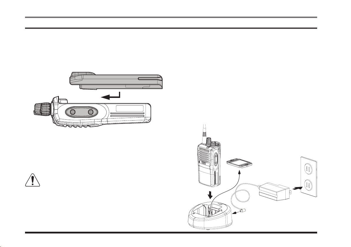
Battery Pack Installation and Removal
To install the battery pack, align the battery pack to the
r
radio with an offset about 1/2 inch (1.5 cm) from the
top edge of battery compartment, then slide the battery
pack upward until it locks in place with a “Click.”
To remove the battery, turn the radio off and remove
r
any protective cases. Slide the Battery Pack Latch on
the bottom of the radio toward the front panel while
sliding the battery down about 1/2 inch (1.5 cm). Then
lift the battery out from the radio.
Do not attempt to open any of the rechargeable
Lithium-Ion packs, as they could explode if ac-
cidentally short-circuited.
Battery Charging
Remove the Spacer Plate from the nest of the optional
r
Desktop Charger, if the Battery Spacer is in-
CD-58
stalled.
Insert the DC p lug from t h e optional
r
Adapter into the DC jack on the rear panel of the optional
PA-55
Insert the battery pack into the
r
ger while aligning the slots of the battery pack with the
guides in the nest of the
ing illustration for details on proper positioning of the
Desktop Charger, and then connect the
CD-58
AC Adapter to the AC line outlet.
CD-58
; refer to the follow-
CD-58
Spacer Plate
PA-55
PA- 5 5
Desktop Char-
AC Line Outlet
AC
CD-58
6
Page 9

beFore you begin
battery pack. If charging with the transceiver attached,
turn the transceiver off. The antenna jack should be at
the left side when viewing the charger from the front.
If the battery pack is inserted correctly, the LED in-
r
dicator will glow red. A fully-discharged battery pack
will charge completely in 1.5 - 3.0 hours (depending
on the battery pack being charged).
When charging is completed, the LED indicator will
r
change to green.
Disconnect the battery pack from the
r
Charger and unplug the
AC line outlet.
1) Always use the M otoro la Solutions FNB V133LI-UNI or FNB-V134LI-UNI Lithium-Ion
Battery Pack.
2) Use only the Motorola Solutions CD-58 Desktop
Charger and the Motorola Solutions PA-55 AC Adapter.
3) To reduce the risk of explosion, recharge the batteries
outside of hazardous locations.
4) Perform the battery charging where the ambient tem-
perature range +41 °F to +104 °F (+5 °C to +40 °C).
Charging outside of this temperature range could cause
damage to the battery pack.
5) Battery Pack should not be exposed to excessive heat
such as sunshine, re, or similar heat sources.
AC Adapter from the
PA-55
CD-58
Desktop
6) Risk of explosion exists if battery is replaced by an
incorrect type. Refer to the enclosed instructions for disposal of used batteries.
7) For further details and cautions of the charging, refer
to the Operating Manual of the CD-58 Desktop Charger.
Low Battery Indication
As the battery discharges during use, the voltage gradually
becomes lower. When the battery voltage becomes too
low, substitute a freshly charged battery and recharge the
depleted pack. The LED indicator on the top of the radio
will blink red when the battery voltage is low.
CAUTION
Danger of explosion if battery is replaced with an
incorrect battery. Replace only with the same or
equivalent type.
VX-261 Operating Manual 7
Page 10

VX-261 Operating Manual
beFore you begin
Belt Clip Installation and Removal
To install the Belt Clip: align the
r
Belt Clip to the groove of the Bat-
tery pack, then press the Belt Clip
downward until it locks in place
with a “Click.”
To remove the Belt Clip: use a
r
at head screw driver to press the
Belt Clip Tab away from the bat-
tery pack to unlock the Belt Clip,
then slide the Belt Clip upward to
remove it.
Belt Clip Tab
MIC/SP CAP Installation
Install the
plied screws.
Use only the supplied screws
r
This radio does not k eep the
r
MIC/SP
when install the
Water Resistant Rating (IP55)
when the
stalled in the
cap with the sup-
MIC/SP
MIC/SP
cap is not in-
MIC/SP
cap.
jack.
8
Page 11
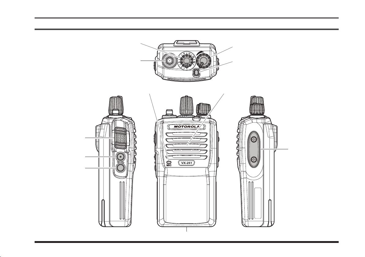
controls & connectors
PTT Switch
SIDE-1 Button
SIDE-2 Button
CH (Channel) Selector
Antenna Jack
VOL (Volume)/PWR (Power) Knob
LED Indicator (Programmable
Default settings are:
Steady Red: Transmitting in progress
Blinking Green: Busy Channel
Steady Green: Tone Squelch in defeated condition
SpeakerMicrophone
MIC/SP Jack
(
External MIC/SP
)
)
Battery Pack Latch
VX-261 Operating Manual 9
Page 12

VX-261 Operating Manual
oPeration
Preliminary Steps
Install a charged battery pack onto the transceiver, as
r
described previously.
Scr e w the suppl i e d ante n n a
r
onto the Antenna jack.
It is not recommended to oper-
ate this transceiver without an
antenna connected.
If you have a Speaker/Micro-
r
phone, we recommend that it
not be connected until you are
familiar with the basic operation of the
next page for more information
about Speaker/Microphone usage.
The water resistance rating of the transceiver (IP55)
is assured only when the following conditions are
met:
Battery pack is attached to the transceiver;
r
Antenna is connected to the antenna jack;
r
MIC/SP
r
Use of a speaker microphone in the
r
jack negates the IP55 rating.
VX-261
cap is installed in the
. Refer to
IMPORTANT NOTE
MIC/SP
jack.
MIC/SP
Operation Quick Start
Tu rn th e t o p pa n e l ’s
r
VOL/PWR
wise to turn the radio on.
Turn the top panel’s CH
r
Selector knob to choose
the de s i red op e rat i ng
channel.
Rotat e the
r
knob to set the volume
le ve l. I f no si g n a l is
present, press (or press
and hold) the Programmable key (assigned to
the “
tion: Normally
now be heard, and you may use this to set the
PWR
and hold) the Programmable key again to quiet the
knob clock-
VO L / P W R
sQl oFF
knob for the desired audio level. Press (or press
” func-
SIDE-1
button); background noise will
VOL/
10
Page 13

noise and resume normal
(quiet) monitoring.
To transmit, monitor the
r
channel and make sure it
is clear.
Press and hold the
sw itch. S peak in to the
microphone area of the
front pa n e l grille in a
normal voice level. To return to the Receive mode, release the
Press (or press and hold)
r
the
SIDE- 1
button to activate one
2
of the pre-programmed
fu n ct i on s w hi c h ma y
have been enabled at the
time of programming by
the dealer. See the next chapter for details regarding
feature availability for this radio.
PTT
switch.
or
PTT
SIDE-
oPeration
If a Speaker/Microphone
r
Note 1): Save the original plastic cap and its mount-
2) When you press the PTT switch on the Speaker/
If the BCLO (Busy Channel Lockout) feature has been
r
is available, remove the
plastic cap and its two
mounti ng screws from
t h e ri g h t si d e of th e
transceiver, th en align
th e co nn e c t o r of th e
Speaker/Microphone on
the radio; secure the connector pin using the screws supplied with the Speaker/
Microphone. Hold the speaker grille up next to your
ear while receiving. To transmit, press the
on the Speaker/Microphone, just as you would on the
main transceiver ’s body, and speak into the micro-
phone on a normal voice level.
ing screws. They should be reinstalled when not using the Speaker/Microphone.
Microphone, it disables the internal microphone, and
vice versa.
programmed on a channel, the radio will not transmit
when a carrier is present. Instead, the radio will gener-
ate short beep three times. Release the
wait for the channel to be clear of activity.
PTT
switch
PTT
switch and
VX-261 Operating Manual 11
Page 14

VX-261 Operating Manual
If the BTLO (Busy Tone Lockout) feature has been
r
programmed on a channel, the radio can transmit only
when there is no carrier being received or when the
carrier being received includes the correct tone (CTCSS
tone or DCS code).
oPeration
Automatic Time-Out Timer
If the selected channel has been programmed for auto-
matic time-out, you must limit the length of each transmission. While transmitting, a beep will sound 10 seconds
before time-out. Another beep will sound just before the
deadline; the top panel’s red LED (“TX” indicator) will
disappear and transmission will cease soon thereafter. To
resume transmitting, you must release the
wait for the “penalty timer” to expire.
switch and
PTT
12
Page 15

advanced oPeration
Programmable Key Functions
The
keys:
VX-261
provides two Programmable Function
SIDE-1
and
SIDE-2
keys.
Both PF keys can be customized, via programming by
your Motorola Solutions dealer, to meet your communications/network requirements.
The possible PF key programming features are illustrated
at the right, and their functions are explained beginning
after next page. For further details, contact your Motorola
Solutions dealer.
For future reference, check the box next to each function
that has been assigned to the PF key on your particular
radio, and keep it handy.
(PF)
Programmable Key
(
Function
None / /
Monitor / /
Monitor -Momentarily- /--- /--Low Power / /
SQL OFF / /
SQL OFF -Momentarily- /--- /--Beep OFF / /
Whisper / /
VOX / /
VOX Anti-Trip / /
Emergency --- / --- /
Lone Worker / /
PRI / /
Scan / /
Dual Watch / /
Follow-Me Scan / /
TA (Talk Around) Scan / /
Talk Around / /
Reset / /
Call 1 / /
Call 2 / /
Call 3 / /
Speed Dial / /
Call / /
Duty / /
TX Save Disable / /
Lock / /
Press Key / Press and hold Key
SIDE-1 SIDE-2
)
VX-261 Operating Manual 13
Page 16

VX-261 Operating Manual
advanced oPeration
Description of Operating Functions
monitor
Press, (or press and hold), the assigned PF key to cancel
any signaling features; the LED indicator will glow green.
monitor -momentarily-
Cancel any signaling features while pressing the assigned
key.
PF
loW PoWer
Press, (or press and hold), the assigned PF key to set the
radio’s transmitter to “Low Power” mode, thus extending
battery life. Press, (or press and hold), the assigned PF
key again to return to “Normal” transmit power when in
RF impeding environments.
sQl oFF
Press, (or press and hold), the assigned PF key to open the
SQL to hear background noise (unmute the audio).
sQl oFF -momentarily-
Opens the SQL to hear background noise (unmute the audio) while pressing the assigned PF key.
beeP oFF
Press, (or press and hold), the assigned PF key to disable any radio beeps temporarily. Press again, (or press
and hold again), the assigned PF key to enable any radio
beeps.
WhisPer
Press, (or press and hold), the assigned PF key to increase
the microphone gain; allowing the operator to speak in a
low voice (whisper) temporarily when transmitting. Press
again, (or press and hold again), the assigned PF key to
resume normal microphone gain.
(reQuires voX comPatible headset
voX
Press, (or press and hold), the assigned PF key to activate
the VOX function; allowing hands-free, automatic activation of the transmitter, initiated by voice input into the
microphone. You may disable the VOX function temporarily by pressing the
Press again, (or press and hold again), the assigned PF
key to resume normal operation.
PTT
switch.
)
voX anti-triP
Press, (or press and hold), the assigned PF key to toggle
the VOX Anti-Trip feature “On” and “Off”.
When the VOX Anti-Trip feature is set to “On”, the transceiver does not activate a VOX transmission from picking
up receive audio or from a radio alert tone (beep sound).
14
Page 17

advanced oPeration
emergency
The
VX-261
be useful for alerting another party monitoring on the
same frequency as your transceiver’s channel. Please contact your Motorola Solutions dealer for further details.
includes an “Emergency” feature which may
scan
The Scanning feature is used to monitor multiple chan-
nels programmed into the transceiver. When scanning, the
transceiver will check each channel for the presence of a
signal and will stop on a channel if a signal is present.
Press and hold the assigned PF key for a pre-programmed
period to initiate an emergency call on the pre-defined
channel.
To revive the radio from the Emergency mode, just press
and hold again the assigned PF key or turn off the radio.
lone WorKer
Press, (or press and hold), the assigned PF key to activate
the Lone Worker feature. The Lone Worker feature is
designed to emit an alarm for 30 seconds when the Lone
Worker Timer (programmed by your Motorola Solutions
dealer) has expired.
Press again, (or press and hold again), the assigned PF
key, the Lone Worker feature is disabled. If the user does
not reset the timer by pressing the
switches to Emergency mode.
switch, the radio
PTT
Pri
Press, (or press and hold), the assigned PF key to recall
the pre-programmed Priority Channel by your Motorola
Solutions dealer directly.
To activate scanning:
Press, (or press and hold), the assigned PF key to acti-
r
vate scan mode.
The scanner will search the channels of the pre-pro-
r
grammed scan list, looking for an active channel. The
radio will pause each time it nds a channel on which
someone is speaking.
Press again, (or press and hold again), the assigned PF
r
key to disable scanning and receive the channel which
was chosen when pressed the PF key.
Note: Your dealer may have programmed your radio to
stay on one of the following channels if you press the
switch during scanning pause:
PTT
“Scan Pause” channel (“Talk Back”)
“Last Busy” channel
“Priority” channel
“User Programmed” channel (“Select Channel”)
The channel which defined in the CH Selector
knob.
VX-261 Operating Manual 15
Page 18

VX-261 Operating Manual
advanced oPeration
dual Watch
The Dual Watch feature is similar to the SCAN feature,
except that only two channels are monitored:
The current operating channel
The Priority channel.
To activate Dual Watch:
Press, (or press and hold), the assigned PF key to acti-
r
vate the Dual Watch feature.
The scanner will search the two channels and pause
r
when it nds a transmission on either channel.
To stop Dual Watch:
Press, (or press and hold), the assigned PF key to dis-
r
able the Dual Watch feature. The radio receives the
channel which was selected by the CH Selector knob.
FolloW me scan
The Follow Me Scan feature checks a user-assigned priority channel in addition to the channels previously pre-
programmed into a radio’s scan list. For example, if only
Channels 1, 3, and 5 (of the 8 available channels) are
designated for “Scanning”, the user may assign Channel 2
as the “user-assigned” priority channel via the Follow Me
Scan.
To activate Follow Me Scan, rst select the channel you
want to designate as the “user-assigned priority channel”
by positioning the CH Selector knob on the desired “priority” channel. Next, press, (or press and hold), the assigned PF key. Finally, rotate the CH Selector knob to the
desired “operating channel”.
The scanner will search the two channels (user-assigned
priority channel and operating channel) and pause when it
nds a transmission on either channel.
16
Page 19

advanced oPeration
ta (talK around
Press, (or press and hold), the assigned PF key to toggle
the TA Scan feature “On” and “Off”.
When operating on a duplex channel system (for example,
a repeater station), TA Scan allows the transceiver to
search both transmit and receive frequencies on your du-
plex system.
When a signal is encountered on the receive frequency,
the transceiver will pause until the signal disappears.
When a signal is encountered on the transmit frequency,
the transceiver will check for activity on the receive fre-
quency every few seconds (interval programmed by your
Motorola Solutions dealer).
Note: The TA Scan feature does not activate on a Simplex
Channel.
)
scan
talK around
Press, (or press and hold), the assigned PF key to activate
the Talk Around feature when you are operating on duplex
channel systems (separate receive and transmit frequencies, utilizing a “repeater” station). The Talk Around
feature allows you to bypass the repeater station and talk
directly to a station that is nearby. This feature has no ef-
fect when you are operating on “simplex” channels, where
the receive and transmit frequencies are already the same.
Note that your dealer may have mode provision for “Talk
Around” channels by programming “repeater” and “Talk
Around” frequencies on two adjacent channels. If so, the
key may be used for one of the other Pre-Programmed
Functions.
Note: The Talk Around feature does not activate on a Sim-
plex Channel.
reset
Press (or press and hold) the assigned PF key to reset the
RFC (Ready for Communication) condition.
call 1 to call 3
Press, (or press and hold), the assigned PF key to send a
pre-programmed 5-Tone call signal.
VX-261 Operating Manual 17
Page 20

VX-261 Operating Manual
advanced oPeration
sPeed dial
Your Motorola Solut i o n s dealer m a y have p r e - p r o grammed Auto-Dial telephone number memories into
your radio.
To dial a number:
Press, (or press and hold), the assigned PF key to send a
pre-dened DTMF tone. The DTMF tones sent during the
dialing sequence will be heard in the speaker.
call
Press, (or press and hold), the assigned PF key to send a
pre-programmed 2-Tone encode code.
duty
Press, (or press and hold), the assigned PF key to toggle
the Duty function of the 2-Tone or 5-Tone “On” and “Off”.
When the Duty function is set to “On”, the user will always hear (depending on the sub-audio signaling) all traf-
c on the paging channel. The radio will sound the paging
alert when it receives the programmed 2-Tone or 5-Tone.
When the Duty function is set to “Off”, the user will NOT
hear normal radio trafc on the paging channel. The radio
will sound the paging alert and unmute only when it receives the programmed 2-Tone or 5-Tone.
tX save disable
The Transmit Battery Saver helps extend battery life by
reducing transmit power when a very strong signal from
an apparently nearby station is being received. Caution
is advised when using this feature, as your transmission
power could degrade the audio heard by the receiving radios in your communication path.
Press, (or press and hold), the assigned PF key to disable
the Transmit Battery Saver, if you are operating in a loca-
tion where high power is almost always needed.
Press again, (or press and hold again), the assigned PF
key, the Transmit Battery Saver activates to reduce the
transmit power when a very strong signal from an apparently nearby station is being received.
locK
Press (or press and hold) the assigned PF key to lock the
Selector knob, Programmable keys, and
CH
PTT
switch.
18
Page 21

locK
In order to prevent accidental channel change or inad-
vertent transmission, various aspects of the CH Selector knob, Programmable keys, and
locked. The precise lockout conguration is programmed
by your Dealer.
To activate the key locking, turn the radio off. Then, press
and hold the
on again.
To cancel the key locking, repeat this process.
PTT
and
SIDE-2
key while turning the radio
switch may be
PTT
(
arts™
This system is designed to inform the operator when you
and another ARTS™-equipped transceivers and stations
are within communication range using the DCS Encoder/
Decoder.
During ARTS™ operation, when the radio receives an
incoming ARTS™ signal, a short beep will sound. If you
move out of range for more than two minutes, your radio
senses that no signal has been received; a short triple-beep
will sound. If you move back into communication range,
as soon as the other station transmits, a short beep will
sound again.
auto range transPond system
)
VX-261 Operating Manual 19
Page 22

FNB-V133LI-UNI
FNB-V134LI-UNI
CD-58
PA-55
A4B-1
B4B
VAC-UNI
VAC-6058
MH-37
MH-45
MH-100
(for MH-45
A4B
A4B
MH-101
MH-102
MH-360S
MH-450S
VH-150A
VH-150B
VCM-5
7.4V DC , 1380 mAh Li-Ion Battery Pack
7.4V DC , 2300 mAh Li-Ion Battery Pack
Desktop Charger
AC Adapter for CD-58
Desktop Charger (CD-58 + PA-55)
Multi-Unit Charger
Earpiece Microphone
Noise Cancelling Speaker Microphone
Receive Only Earpiece
B4B
1 Wire Surveillance Kit
2 Wire Surveillance Kit
Compact Speaker Microphone
Speaker Microphone
Behind Type VOX Compatible Microphone
Over the Head VOX Compatible Microphone
Vehicular Charger Mounting Adapter for CD-58
oPtional accessories
/-360S/-450S)
ATV-8A
ATV-8B
ATV-8C
ATV-6XL
ATU-6A
ATU-6B
ATU-6C
ATU-6D
ATU-6F
CN-3
CLIP-20
CE150
FIF-12
CT-106
CT-27
VHF Antenna (134-151 MHz)
VHF Antenna (150-163 MHz)
VHF Antenna (161-174 MHz)
VHF Antenna (Untuned)
UHF Antenna (400-430 MHz)
UHF Antenna (420-450 MHz)
UHF Antenna (440-470 MHz)
UHF Antenna (450-490 MHz)
UHF Antenna (490-520 MHz)
Antenna Adapter
Belt Clip
PC Programming Software
USB Programming Interface
Connection Cable for FIF-12
Radio to Radio Cloning Cable
Availability of accessories may vary; some accessories are supplied stan dard p er local requirements, others may be unavailable in some
regions. Check with your Motorola Solutions
Dealer for changes to this list.
20
VX-261 Operating Manual
Page 23

Warranty Policy
Motorola Solutions warrants, to the original purchaser only, its Motorola Solutions manufactured communications products
against defects in materials and workmanship under normal use and service for a given period of time from the date of purchase.
Limited Warranty Details:
Contact the authorized Motorola Solutions distributor in your country.
Disposal of your ElEctronic anD ElEctric EquipmEnt
Products with the symbol (crossed-out wheeled bin) cannot be disposed as household waste.
Electronic and Electric Equipment should be recycled at a facility capable of handling these items and
their waste by products.
In EU countries, please contact your local equipment supplier representative or service center for information about the waste collection system in your country.
Part 15.21: Changes or modications to this device not expressly approved by Motorola Solutions could void the
user’s authorization to operate this device.
Page 24

No portion of this manual may be reproduced without the per-
mission of Motorola Solutions, Inc.
MOTOROLA, MOTO, MOTOROLA SOLUTIONS and Styl-
ized M logo are trademarks or registered trademarks of Motoro-
la Trademark Holdings, LLC and are used under license.
All other trademarks are the property of their respective owners.
©2017 Motorola Solutions, Inc.
All rights reserved.
Motorola Solutions, Inc.
500 W. Monroe Street Chicago, IL 60661 USA
 Loading...