

Page 1
Level III Service Manual
Wireless Telephone
V70
GSM 1900 MHz & GPRS Technologies
Page 2

Page 3

1 and 2
C23
Level III Service Manual Table of Contents
6881039B25
Table of Contents
Table of Contents
Introduction . . . . . . . . . . . . . . . . . . . . . . . . . . . . . . . . . . . . . . . . . . . . . . . . . . . . . . . . . . . . . . . . . . . . . . . . . . . . . . 1
Product Identification . . . . . . . . . . . . . . . . . . . . . . . . . . . . . . . . . . . . . . . . . . . . . . . . . . . . . . . . . . . . . . . . 1
Product Names . . . . . . . . . . . . . . . . . . . . . . . . . . . . . . . . . . . . . . . . . . . . . . . . . . . . . . . . . . . . . . . . . . . . . 1
Product Changes . . . . . . . . . . . . . . . . . . . . . . . . . . . . . . . . . . . . . . . . . . . . . . . . . . . . . . . . . . . . . . . . . . . . 1
Regulatory Agency Compliance . . . . . . . . . . . . . . . . . . . . . . . . . . . . . . . . . . . . . . . . . . . . . . . . . . . . . . . . 1
Computer Program Copyrights . . . . . . . . . . . . . . . . . . . . . . . . . . . . . . . . . . . . . . . . . . . . . . . . . . . . . . . . 2
About This Service Manual . . . . . . . . . . . . . . . . . . . . . . . . . . . . . . . . . . . . . . . . . . . . . . . . . . . . . . . . . . . 2
Warranty Service Policy . . . . . . . . . . . . . . . . . . . . . . . . . . . . . . . . . . . . . . . . . . . . . . . . . . . . . . . . . . . . . . 3
Parts Replacement . . . . . . . . . . . . . . . . . . . . . . . . . . . . . . . . . . . . . . . . . . . . . . . . . . . . . . . . . . . . . . . . . . 4
Specifications . . . . . . . . . . . . . . . . . . . . . . . . . . . . . . . . . . . . . . . . . . . . . . . . . . . . . . . . . . . . . . . . . . . . . . . . . . . . 5
Product Overview . . . . . . . . . . . . . . . . . . . . . . . . . . . . . . . . . . . . . . . . . . . . . . . . . . . . . . . . . . . . . . . . . . . . . . . . . 7
Features . . . . . . . . . . . . . . . . . . . . . . . . . . . . . . . . . . . . . . . . . . . . . . . . . . . . . . . . . . . . . . . . . . . . . . . . . . . 7
General Operation . . . . . . . . . . . . . . . . . . . . . . . . . . . . . . . . . . . . . . . . . . . . . . . . . . . . . . . . . . . . . . . . . . . . . . . . 10
Controls, Indicators, and Input / Output (I/O) Connectors . . . . . . . . . . . . . . . . . . . . . . . . . . . . . . . . . 10
User Interface Menu Structure . . . . . . . . . . . . . . . . . . . . . . . . . . . . . . . . . . . . . . . . . . . . . . . . . . . . . . . 12
Alert Settings . . . . . . . . . . . . . . . . . . . . . . . . . . . . . . . . . . . . . . . . . . . . . . . . . . . . . . . . . . . . . . . . . . . . . 12
Battery Function . . . . . . . . . . . . . . . . . . . . . . . . . . . . . . . . . . . . . . . . . . . . . . . . . . . . . . . . . . . . . . . . . . . 13
Operation . . . . . . . . . . . . . . . . . . . . . . . . . . . . . . . . . . . . . . . . . . . . . . . . . . . . . . . . . . . . . . . . . . . . . . . . . 13
Tools and Test Equipment . . . . . . . . . . . . . . . . . . . . . . . . . . . . . . . . . . . . . . . . . . . . . . . . . . . . . . . . . . . . . . . . . 15
Disassembly . . . . . . . . . . . . . . . . . . . . . . . . . . . . . . . . . . . . . . . . . . . . . . . . . . . . . . . . . . . . . . . . . . . . . . . . . . . . . 16
Removing and Replacing the Battery Cover and Battery . . . . . . . . . . . . . . . . . . . . . . . . . . . . . . . . . . 16
Removing and Replacing the Subscriber Identity Module (SIM) . . . . . . . . . . . . . . . . . . . . . . . . . . . . . 19
Removing and Replacing the Rear Housing Cover . . . . . . . . . . . . . . . . . . . . . . . . . . . . . . . . . . . . . . . . 20
Removing and Replacing the Rear Transceiver Housing . . . . . . . . . . . . . . . . . . . . . . . . . . . . . . . . . . . 21
Removing and Replacing the Antenna . . . . . . . . . . . . . . . . . . . . . . . . . . . . . . . . . . . . . . . . . . . . . . . . . 22
Removing and Replacing the Transceiver Board Assembly . . . . . . . . . . . . . . . . . . . . . . . . . . . . . . . . . 23
Removing and Replacing the Daughter PC Board . . . . . . . . . . . . . . . . . . . . . . . . . . . . . . . . . . . . . . . . 24
Removing and Replacing the Real Time Clock Battery . . . . . . . . . . . . . . . . . . . . . . . . . . . . . . . . . . . . 25
Removing and Replacing the Keypad . . . . . . . . . . . . . . . . . . . . . . . . . . . . . . . . . . . . . . . . . . . . . . . . . . 26
Removing and Replacing the Keypad PCB Assembly . . . . . . . . . . . . . . . . . . . . . . . . . . . . . . . . . . . . . . 26
Removing and Replacing the Ring Bezel Assembly . . . . . . . . . . . . . . . . . . . . . . . . . . . . . . . . . . . . . . . 28
Removing and Replacing the Display Module . . . . . . . . . . . . . . . . . . . . . . . . . . . . . . . . . . . . . . . . . . 29
Removing and Replacing the Microphone . . . . . . . . . . . . . . . . . . . . . . . . . . . . . . . . . . . . . . . . . . . . . . . 32
Subscriber Identity Module (SIM) and Identification Label . . . . . . . . . . . . . . . . . . . . . . . . . . . . . . . . . . . . . . . 33
SIM . . . . . . . . . . . . . . . . . . . . . . . . . . . . . . . . . . . . . . . . . . . . . . . . . . . . . . . . . . . . . . . . . . . . . . . . . . . . . 33
Identification . . . . . . . . . . . . . . . . . . . . . . . . . . . . . . . . . . . . . . . . . . . . . . . . . . . . . . . . . . . . . . . . . . . . . . 33
Troubleshooting . . . . . . . . . . . . . . . . . . . . . . . . . . . . . . . . . . . . . . . . . . . . . . . . . . . . . . . . . . . . . . . . . . . . . . . . . 35
Manual Test Mode . . . . . . . . . . . . . . . . . . . . . . . . . . . . . . . . . . . . . . . . . . . . . . . . . . . . . . . . . . . . . . . . . 35
Manual Test Mode Commands . . . . . . . . . . . . . . . . . . . . . . . . . . . . . . . . . . . . . . . . . . . . . . . . . . . . . . . . 35
Troubleshooting Chart . . . . . . . . . . . . . . . . . . . . . . . . . . . . . . . . . . . . . . . . . . . . . . . . . . . . . . . . . . . . . . 37
Programming: Software Upgrade and Flexing . . . . . . . . . . . . . . . . . . . . . . . . . . . . . . . . . . . . . . . . . . . 3 8
Part Number Charts . . . . . . . . . . . . . . . . . . . . . . . . . . . . . . . . . . . . . . . . . . . . . . . . . . . . . . . . . . . . . . . . . . . . . . . 39
Related Publications . . . . . . . . . . . . . . . . . . . . . . . . . . . . . . . . . . . . . . . . . . . . . . . . . . . . . . . . . . . . . . . . 39
Exploded View Diagram . . . . . . . . . . . . . . . . . . . . . . . . . . . . . . . . . . . . . . . . . . . . . . . . . . . . . . . . . . . . . 40
Exploded View Parts List . . . . . . . . . . . . . . . . . . . . . . . . . . . . . . . . . . . . . . . . . . . . . . . . . . . . . . . . . . . 41
Model-Specific Part Numbers . . . . . . . . . . . . . . . . . . . . . . . . . . . . . . . . . . . . . . . . . . . . . . . . . . . . . . . . . 42
Accessories . . . . . . . . . . . . . . . . . . . . . . . . . . . . . . . . . . . . . . . . . . . . . . . . . . . . . . . . . . . . . . . . . . . . . . . . 43
Index . . . . . . . . . . . . . . . . . . . . . . . . . . . . . . . . . . . . . . . . . . . . . . . . . . . . . . . . . . . . . . . . . . . . . . . . . . . . . . . Index-1
6881039B25 January 08, 2002 i
Page 4

1 and 2
C23
Table of Contents
6881039B25
Table of Contents
ii January 08, 2002 6881039B25
Page 5

1 and 2
C23
Level III Service Manual Introduction
6881039B25
Introduction
Motorola® Inc. maintains a worldwide organization that is dedicated to provide
responsive, full-service customer support. Motorola products are serviced by an
international network of company-operated product care centers as well as authorized independent service firms.
Available on a contract basis, Motorola Inc. offers comprehensive maintenance and
installation programs which enable customers to meet requirements for reliable,
continuous communications.
To learn more about the wide range of Motorola service programs, contact your local
Motorola products representative or the nearest Customer Service Manager.
Product Identification
Motorola products are identified by the model number on the housing. Use the entire
model number when inquiring about the product. Numbers are also assigned to
chassis and kits. Use these numbers when requesting information or ordering
replacement parts.
Product Names
Product names included in V70 telephones are listed on
the front cover. Product names are subject to change without notice. Some product
names, as well as some frequency bands, are available only in certain markets.
Product Changes
When electrical, mechanical or production changes are incorporated into Motorola
products, a revision letter is assigned to the chassis or kit affected, for example; A, -B, or -C, and so on.
The chassis or kit number, complete with revision number is imprinted during
production. The revision letter is an integral part of the chassis or kit number and
is also listed on schematic diagrams and printed circuit board layouts.
Regulatory Agency Compliance
This device complies with Part 15 of the FCC Rules. Operation is subject to the
following conditions:
1. This device may not cause any harmful interference, and
2. this device must accept interference received, including interference that may
cause undesired operation.
This class B device also complies with all requirements of the Canadian Interference-Causing Equipment Regulations (ICES-003).
Cet appareil numérique de la classe B respecte toutes les exigences du Règlement
sur le matériel brouilleur du Canada.
6881039B25 January 08, 2002 1
Page 6

6881039B25
C23
Introduction
1 and 2
Computer Program Copyrights
The Motorola products described in this manual may include Motorola computer
programs stored in semiconductor memories or other media that are copyrighted
with all rights reserved worldwide to Motorola. Laws in the United States and ot her
countries preserve for Motorola, Inc. certain exclusive rights to the copyrighted
computer programs, including the exclusive right to copy, reproduce, modify,
decompile, disassemble, and reverse-engineer the Motorola comp uter programs in
any manner or form without Motorola's prior written consent. Furthermore, the
purchase of Motorola products shall not be deemed to grant either directly or by
implication, estoppel, or otherwise, any license or rights under the copyrights,
patents, or patent applications of Motorola, except for a nonexclusive license to use
the Motorola product and the Motorola computer programs with the Motorola
product.
About This Service Manual
Using this service manual and the suggestions contained in it assures proper
installation, operation, and maintenance of V70 telephones. Refer questions
about this manual to the nearest Customer Service M anager.
A product family is the group of products having the same Account Product Code
(APC). To locate the APC on a device, refer to “ Mechanical Serial Number (MSN)”
later in this manual.
Audience
This document aids service personnel in testing and repairing V70 telephones.
Service personnel should be familiar with electronic assembly, testing, and troubleshooting methods, and with the operation and use of associated test equipment.
Use of this document assures proper installation, operation, and maintenance of
Motorola products and equipment. It contains all servic e infor mati on requir ed for
the equipment described and is current as of the printing date.
Scope
The scope of this document is to provide the reader with basic information relating
to V70 telephones, and also to provide procedures and processes for repairing
the units at Level 1 and 2 se rvice center s including:
•Unit swap out
• Repairing of mechanical faults
• Basic modular troubleshooting
• Test ing and verification of unit functionality
• Initiate warranty claims and send faulty modules to Level 3 or 4 repair
centers.
2 January 08, 2002 6881039B25
Page 7

Level III Service Manual Introduction
Conventions
Special characters and typefaces, listed and described below, are used in this
publication to emphasize certain types of information.
➧
G
E
E
Revisions
Any changes that occur after manuals are printed are described in publication
revision bulletins (PMRs). These bulletins provide change information that can
include new parts listing data, schematic diagrams, and printed board layouts.
Warranty Service Policy
Note: Emphasizes additional information pertinent to the subject
matter.
Caution: Emphasizes information about actions which may result in
equipment damage.
Warning: Emphasizes information about actions which may result
in personal injury.
Key s to be pressed are represented graphi cally. For e xample , instead of “Press
the Enter Key”, you will see “Press E”.
Information from a screen is shown in text as similar as possible to what
appears in the display. For example, ALERTS or ALERTS or ALERTS.
Information that you need to type is printed in boldface type
The product will be sold with the standard 12 months warranty terms and conditions. Accidental damage, misuse, and extended warranties offered by retailers are
not supported under warranty. Non warranty repairs are available at agreed fixed
repair prices.
Out of Box Failure Policy
The standard out of box failure criteria applies. Customer units that fail very early
on after the date of sale, are to be returned to Manufacturing for root cause analysis,
to guard against epidemic criteria. Manufacturing to bear the costs of early life
failure.
Product Support
Customer’s original units will be repaired but not refurbished as standard. Appointed Motorola Service Hubs will perform warranty and non-warranty field service for
level 2 (assemblies) and level 3 (limited PCB component). The Motorola HTC centers
will perform level 4 (full component) repairs.
6881039B25 January 08, 2002 3
Page 8

Introduction
Customer Support
Customer support is available through dedicated Call Centers and in-country help
desks. Product Service training should be arranged through the local Motorola
Support Center.
Parts Replacement
When ordering replacement parts or equipment, include the Motorola part number
and description used in the service manual or supplement.
When ordering crystals or channel elements, specify the Motorola part number,
description, crystal frequency, and operating frequency desired.
When the Motorola part number of a component is not known, use the product model
number or other related major assembly along with a description of the related
major assembly and of the component in question.
In the U.S.A., to contact Motorola, Inc. on your TTY, call: 800-793-7834
Accessories and Aftermarket Division (AAD)
Replacement parts, test equipment, and manuals can be ordered from AAD.
U.S.A Outside U.S.A.
Phone: 800-422-4210 Phone: 847-538-8023
FAX: 800-622-6210 FAX: 847-576-3023
4 January 08, 2002 6881039B25
Page 9
Level III Service Manual Specifications
Specifications
Table 1. Specifications
General Function Specification
Frequency Range PCS
Channel Spacing 200 kHz
Channels
Modulation GMSK at BT = 0.3
Transm itter Phase Accuracy 5 Degrees RMS, 20 Degrees peak
Duplex Spacing 45 MHz GSM, 95 MHz DCS
Frequency Stability ± 0.10 ppm of the downlink frequency (Rx)
Operating Voltage
Average Transmit Current 300 mA
Average Stand-by Current 7 mA
Dimensions
Size (Volume) 56 cc (3.42 in
Weight 83 gm (2.93 o z )
Temperature Range -10° C to +55° C (+15° F to +130° F)
Battery Life, 700 mAh Li Polymer
Battery
Battery Life, 400 mAh Li Polymer
Battery
1850.2-1909.8MHzTx
1930.2 - 1989.8 MHZ Rx
174 EGSM, 374 DCS carriers with 8 ch.
per carrier
+3.0V dc to +5.1V dc (battery)
+4.4V dc to +6.5V dc (external connector)
94 mm x 38 mm x 18.3 mm (3.7 inches x
1.5 inches x 0.72 inches)
Talk time up to 130 minutes
Standby time up to 140 hours
Talk time up to 130 minutes
Standby time up to 140 hours
All talk and standb y tim es are ap proximate
and depend on network configuration,
signal strength, and features selected.
Standby times are quoted as a range from
DRX=2 to DRX=9. Talk times are quoted
as a range from DTX off to DTX on.
3
)
Transmitter Function
RF Power Output
Output Impedance 50 ohms nominal
Spurious Emissions
Receiver Function
Receive Sensitivity -107 dBm GSM, -105 dBm DCS
RX bit error rate (100k bits) Type II < 2%
Channel Hop Time 500 microseconds
Time to Camp Approximately 5-10 seconds
33 dBm nominal GSM
30 dBm nominal DCS
-36 dBm from 0.1 to 1 GHz,
-30 dBm from 1 to 4 GHz
6881039B25 January 08, 2002 5
Page 10

Specifications
Speech Coding Function Specification
Speech Codi ng Type
Bit Rate 13.0 kbps
Frame Duration 20 ms
Block Length 260 bits
Classes Class 1 bits = 182 bits; Class 2 bits = 78 bits
Bit Rate with FEC Encoding 22.8 kbps
Regular pulse e xcita tion / line ar predict ive coding
with long term prediction (RPE LPC with LTP)
6 January 08, 2002 6881039B25
Page 11

Level III Service Manual
Product Overview
Motorola V70 mobile telephones feature global system for mobile communications (GSM) air interface, general packet radio service (GPRS) transport technology,
and wireless application protocol (WAP) Internet browser. V70 telephones
incorporate a simplified icon and list-based user interface (UI) for easier operation,
allow short message service (SMS) text messaging, and include clock, alarm,
datebook, calculator, and caller profiling personal management tools. The PF 23 is
a single band phone that allows roaming within the GSM 1900 MHz band
V70 telephones support GPRS and SMS in addition to traditional circuit
switched transport technologies. GPRS, where available, provides substantial
increases in mobile data communications performance and the efficient use of radio
spectrum. Data transmission rates for GSM networks can potentially increase fro m
the current rate of 9.6 kbps up to a theoretical maximum of 171.2 kbps. An increased
data rate is by no means the only ben efit provided by GPRS. A key advantage is
the provision of a permanent virtual connection to the network. This “always on”
connection is possible because GPRS uses packet data transfer so, for example,
email can be downloaded in “background mode.” Th ere is no need for the user to reconnect before requesting a service, eliminating connection set-up delays and
adding convenience and immediacy to data services access. The “virtual” nature of
this connection means that network resources are not consumed during periods
when a user is not actually sending or receiving data.
Features
The telephones are made of polycarbonate plastic with a metal enclosure. The
display and speaker, as well as the 16-key keypad, transceiver printed circuit board
(PCB), microphone, charger and headphone connectors, and power button are
contained within the rotator form-factor housing. The user-replaceable 600 mAh
nickel metal hydride (NiMH) battery prov ides up to 300 minutes of talk time with
up to 180 hours of standby time
1
. The phone accepts 3V mini subscriber identity
module (SIM) cards which fit into the SIM hold er next to the battery. These
telephones feature a 96 x 64 pixel 800 square millimeter high-resolution graphics
display and an internal antenna.
V70 telephones use advanced, self-contained, sealed, custom integrated circuits
to perform the complex functions required for GSM GPRS communication. Aside
from the space and weight advantage, microcircuits enhance basic reliability,
simplify maintenance, and provide a wide va riety of operational functions.
Features available in this family of telephones include:
• Lower voltage technology that provides increased standby and talk times
• Extended GSM (EGSM) channels
• Tri-coder/decoder (CODEC) that allows full rate, half rate, and enhanced full
rate modes of transmission
• Supports SMS, concatenated SMS, and cell broadcast messages
• Supports GPRS, circuit switched, and SMS networks
• WAP 1.1 compliant
2
2
2
1. All talk and standby times are approximate and depend on network configuration, signal strength, and features selected. Standby
times are quoted as a range from DRX=2 to DRX=9. Talk times are quoted as a range from DTX off to DTX on.
2. Network, subscription and SIM card or service provider dependent feature. Not available in all areas.
6881039B25 January 08, 2002 7
Page 12

Product Overview
• 96 X 64 pixel inverse graphical display with 3 lines of English text, 1 line of
icons, and on e line of prompts
•Display zoom
• Display animation
• VibraCall® vibrating alert
• Downloadable ring tones
• Voice activation for phone book entries
• Simplified text entry using iTAP™ predictive text entry
• Calling line identification
• Supports call forwarding for incoming voice, fax and data calls
• Supports 3V SIM cards
•SIM Toolkit™ Class 2 (STK)
• Personal management tools: calculator with currency converter, real time clock
with date, reminders, and caller profiling
• Phase II Unstructured Supplementary Service Data (USSD)
• Hearing Aid Telephone Interconnection System (HATIS) support
• Micro Browser connection via WAP over GPRS
• Multiple destination SMS
• TrueSync™ Multi-Point Synchronization Capability
• FM Stereo Radio (with optional headset accessory)
3
3
3
3
3
3
➧
➧
➧
Speaker Dependant Voice Activation
The voice dialing feature allows the user to recall pre-programmed voice numbers
simply by pressing the Voice Dial soft key and speaking the desired voice name
entry.
The user cannot place or receive calls while adding voice names to the phone’s
memory.
Because the GSM standard does not provide the option to store voice tags onto the
SIM card, voice tags are added to the phone’s memory.
Wireless Access Protocol (WAP) 1.1 Compliancy
In the WAP environment, access to the Internet is initiated in wireless markup
language (WML), which is derived from hypertext marku p language (HTML). The
request is passed to a WAP gateway which retrieves the information from the server
in standard HTML (subsequently filtered to WML) or directly in WML if available.
The information is then passed to the mobile subscriber via the mobile network.
The V70’s microbrowser can be configured for baud, idle timeout, line type,
phone number, and connection type.
Bitmap image data will download as text. If the image is larger than the screen,
only part of the image will display.
3. Network, subscription and SIM card or service provider dependent feature. Not available in all areas.
8 January 08, 2002 6881039B25
Page 13

Level III Service Manual Product Overview
➧
If the user receives a call while in browser mode, the browser will pause and allow
the user to resume after completing the call.
Simplified Text Entry
Using iTAP™ predictive text entry, pressing a key generates a character and a
dynamic dictionary uses this to build and display a set of word or name opt ions.
The iTAP™ feature may not b e available on the phone in all language s.
Caller Line Identification
Upon receipt of a call, the calling party’s phone number is compared to the phone
book. If the number matches a phone book entry, that name will be displayed. If
there is no phone book entry, the incoming phone number will be displayed. In the
event no caller identification information is available, an incoming call message is
displayed.
➧
User must subscribe to a caller line identification service through their service
provider.
SIM Toolkit™ - Class 2
SIM Application Toolkit is a value-added service delivery mechanism that allows
GSM operators to customize the services they offer customers, from the occasional
user who requests sports news and traffic alerts, to a high call time busines s user
who receives stock alerts and checks flight times. Operators can now create their
own value-added services menu quickly and easily in the phone. The customized
menu will appear as the fi rst menu and may be updated over-the-air with new
services when customers request them.
Personal Information Management
The PF32 telephone contains a built in calendar and phonebook that can be
synchronized easily to a computer or PDA.
Other Features
Detailed descriptions of the se and the other features can be found in the appropriate
V70 telephone user guides listed in the Related Publications section toward the
end of this manual.
6881039B25 January 08, 2002 9
Page 14
General Operation
General Operati on
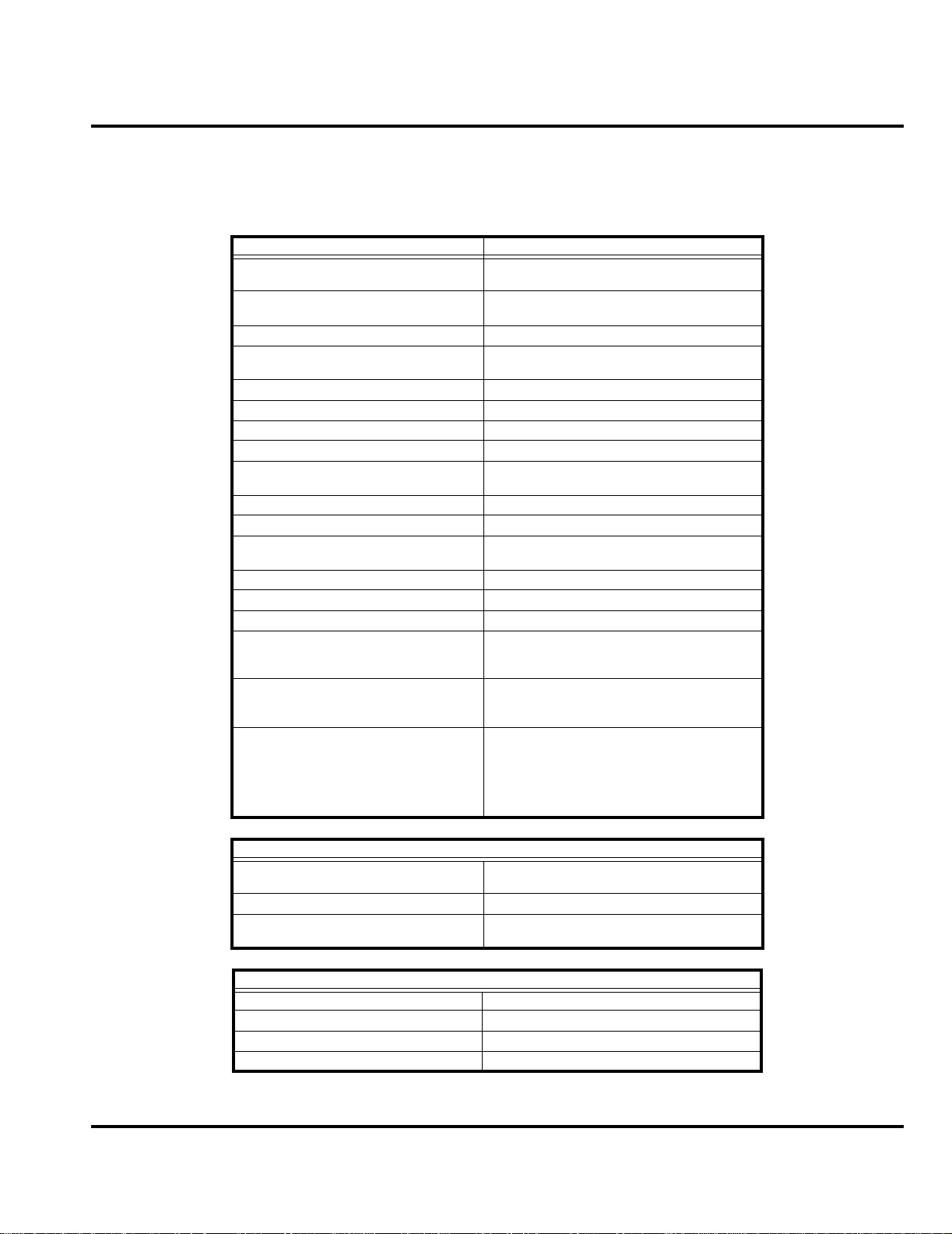
Controls, Indicators, and Input / Output (I/O) Connectors
The V70 telephone’s controls are located on the front and side of the device, and
on the keyboard as shown in Figure 1. Indicators, in the form of icons, are displayed
on the LCD (see Figure 2).
EarpieceHeadset Jack
Insert headset
accessory for
hands-free use.
Front Blade
Display
Volume Key
Adjust earpiece
and ringer volume.
Left Soft Key
Perform functions
identifed by left
display prompt.
Menu Key
Power/End Key
Press & hold to
power phone on &
off.
Press & release to end
phone calls,exit menu
system.
Microphone
Figure 1.V70 Telephone Controls and Indicators Locations
Right Soft Key
Perform functions
identifed by right
display prompt.
Send Key
Send and answer
calls, view recent
dialed calls list.
Navigation Keys
Scroll through
menus and lists,
set feature values.
Accessory
Connector Port
Insert charger and
phone accessories.
Menu Navigation
V70 telephones are equipped with a simplified icon and list-based user interface.
The phone als o features a user-definable Quick Access menu that is accessed by
holding down the MENU key. See Figure 3 for details of the V70 menu structure.
011211-o
Liquid Crystal Display (LCD)
The LCD provides an 800 square millimeter blue backlit display having useradjustable contrast for optimum readability in all light conditions. The large bitmapped 96 x 64 pixel display includes up to 3 lines of text, 1 line of icons, and 1 line
of prompts.
10 January 08, 2002 6881039B25
Page 15
Level III Service Manual General Operation
Display animation makes the phone’s icon menu move smoothly as the user scrolls
up and down.
Whether a phone displays all indicators depends on the programming and services
➧
to which the user subscribes.
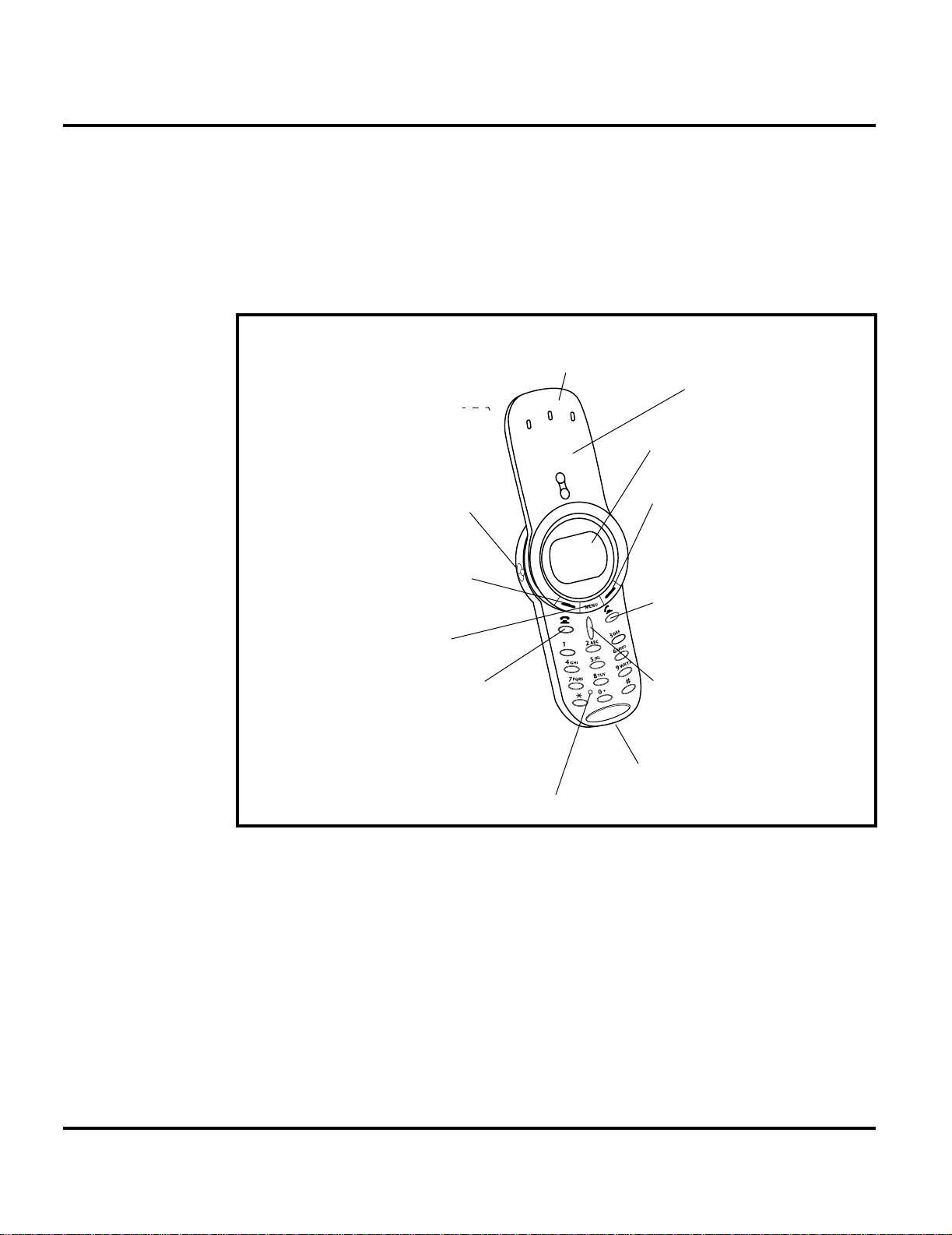
Figure 2 shows some common icons displayed on the LCD.
➋
➊
➓
Alert
Setting
Indicator
In Use
Indicator
Signal
Strength
Indicator
➌
Roam
Indicator
5
O,=&
w
12:00
GPRS
➍
Message Waiting
Indicator
➎
Voice Message
Waiting Indicator
E
am
➏
Battery
Level
Indicator
e
➒
GPRS Indicator
Figure 2.V70 Display Icon Indicators
1. Signal Strength shows the strength of the phone’s connection with the
network. Calls cannot be sent or received when the “no signal” indicator is
displayed.
2. In Use Indicator icon indicates a call in progress.
3. Roam Indicator icon appears when the phone uses another network system
outside the user’s home network . When leaving the home network area, the
phone roams, or seeks, another network.
4. Message Waiting Indicator
sage.
5. Voice Message Waiting Indicator
a voicemail message.
6. Battery Level Indicator shows the amount of charge left in the battery.
7. Real Time Clock shows the current time.
8. Menu Indicator provides access to the phone’s main menu.
9. GPRS Indicator
mode.
10. Alert Setting Indicator indicates the phone’s current ringer alert setting.
4
indicates when the phone is currently functioning in GPRS
➑
Menu Indicator
4
appears when the phone receives a text mes-
4
icon indicates when the phone receives
➐
Clock
011212-o
4. Network, subscription and SIM card or service provider dependent feature. Not available in all areas.
6881039B25 January 08, 2002 11
Page 16
General Operation
User Interface Menu Structure
Figure 3 shows the V70 telephone menu structure.
Main Menu
• Recent Calls
• Received Calls
• Dialed Calls
• Notepad
• Call Times
• Call Cost
• Service Dial
• Fixed Dial
• Phonebook
• Datebook
• Quick Dial
• Radio
• Messages
• Voicemail
• Text Msgs
• Browser Alerts
• Info Services
• Quick Notes
• Outbox
• Drafts
• Shortcuts
• SIM Applications
• Browser
• Calculator
• Games
• Settings
Settings Menu
• Ring/Vibrate
• Alert
Alert
Detail
•
• My Tones
• Call Forward
• Voice Calls
• Fax Calls
• Data Calls
• Cancel All
• Forward Status
• Phone Status
• My Tel. Numbers
• Credit Info/Available
• Active Line
• Battery Meter
• Other Information
• Browser Setup
• In-Call Setup
• In-Call Timer
• Call Cost Setup
• My Caller ID
• Talk and Fax
• Answer Options
• Call Waiting
• Security
• Phone Lock
• Lock Keypad
• Lock Application
• Fixed Dial
• Call Barring
• SIM Pin
• New Passwords
• Other Settings
• Personalize
• Main Menu
• Keys
• Greeting
• Quick Dial
• Initial Setup
• Time and Date
• 1-Touch Dial
• Auto Redial
• Backlight
• Status Light
• Zoom
• Scroll
• Animation
• Language
• Battery Save
• Contrast Setting
• DTMF
• Master Reset
• Master Clear
• Network
• Car Settings
• Headset
011564-o
Figure 3. V70 Menu Structure
Alert Settings
In addition to 11 preset ring tones, V70 telephones allow the user to download
2 additional ring tones via SMS. (Availability is carrier and network dependant).
Motorola V70 phones incorporate the VibraCall® discreet vibrating alert that
helps to avoid disturbing others when a ringing phone is unacceptable.
Alerts can be set to ring only, vibrate only, vibrate then ring, or no ring or vibrate
Additionally, the profiling feature allows users to identify incoming calls by a
specific ringer tone.
12 January 08, 2002 6881039B25
Page 17

Level III Service Manual General Operation
Battery Fu nction
Battery Charge Indicator
The telephone displays a battery charge indicator icon in the idle screen to indicate
the battery charge level. The gauge shows four levels: 100%, 66%, 33%, and Low
Battery.
Battery Removal
Removing the battery causes the device t o immediately shut down and any pending
work (partially entered phone book entries or outgoing messages, for example) is
lost.
All batteries can cause property damage and/or bodily injury such as burns if a
conductive material such as jewelry, keys, or beaded chains touch exposed terminals.
E
The conductive material may complete an electrical circuit (short circuit) and
become quite hot. Exercise care in handling any charged battery, particularly when
placing it inside a pocket, purse, or other container with metal objects.
Operation
G
➧
If the battery is removed while receiving a message, the message will be lost.
To ensure proper memory retention, turn the phone OFF before removing the
battery. Immediately replace the old battery with a fresh battery.
For detailed operating instructions, refer to the appropriate user guide listed in the
Related Publications section toward the end of this manual.
6881039B25 January 08, 2002 13
Page 18

General Operation
14 January 08, 2002 6881039B25
Page 19

1 and 2
Level III Service Manual Tools and Test Equipment
6881039B25
C23
Tools and Test Equipmen t
The following tables list the tools and test equipment used on V70 telephones.
Use either the listed i tems or equivalents.
Table 2. General Test Equipment and Tools
Motorola
Part Number
See Table 7 Charger Used to charge battery and to power device
0180386A82
8102430Z04 GSM / DCS / PCS Test SIM Used to enable manual test mode
6680388B67 Disassembly tool, plastic with flat and pointed
6680388B01 Tweezers, plastic Used during assembly/disassembly
RSX4043-A Torque Driver Used to remove and replace screws
HP34401A
1. To order in North America, contact Motorola Aftermarket and Accessories Division (AAD) by phone at (800) 422-4210 or
FAX (800) 622-6210; Internationally, AAD can be reached by calling (847) 538-8023 or faxing (847) 576-3023.
2. Not available from Motorola. To order, contact Hewlett Packard at (800) 452-4844.
—
1
Antistatic Mat Kit (include s 66-80387A 95 antis tatic
mat, 66-80334B36 groun d cord, and 42- 80385A59
wrist band)
ends (manual opening tool)
Torque Driver Bit T-6 Plus, Apex 440-6 IP Torx Plus
or equivalent
2
Digital Multimeter Used to measure battery voltage
Description Application
Provides protect ion from damage to de vice caused
by electrostatic discharge (ESD)
Used during assembly/di s assembly of device
Used with torque driver
6881039B25 January 08, 2002 15
Page 20

Disassembly
Disassembly
The procedures in this section provide instructions for the disassembly of a V70
telephone. Tools and eq uipment used are listed in Table 2, preceding.
Many of the integrated devices used in this equipment are vulnerable to damage
G
G
Removing and Replacing the Battery Cover and Battery
E
from electrostatic discharge (ESD). Ensure adequate static protection is in place
when handling, shipping, and servicing the internal components of this equipment.
Avoid stressing the plastic in any way to avoid damage to either the plastic or
internal components.
All batteries can cause property damage and/or bodily injury such as burns if a
conductive material such as jewelry, keys, or beaded chains touch exposed terminals.
The conductive material may complete an electrical circuit (short circuit) and
become quite hot. Exercise care in handling any charged battery, particularly when
placing it inside a pocket, purse, or other container with metal objects.
1. Ensure the front blade is closed and the phone is turned off.
16 January 08, 2002 6881039B25
Page 21

Level III Service Manual Disassembly
2. While holding the battery cover release depressed, slide the battery cover
release, slide the battery cover in the direction of the arrow, and lift completely
off the phone (see Figu re 4).
BATTERY COVER
Figure 4. Removing the battery cover
BATTERY COVER
RELEASE
011098-o
BATTERY
011207-o
Figure 5. Removing the battery
6881039B25 January 08, 2002 17
Page 22

Disassembly
3. Remove the battery by lifting its top end from the battery compartment and
sliding it up and away from the compartment as shown in Figure 5.
There is a danger of explosion if the Lithium ion battery is replaced incorrectly.
Replace only with the same type of battery or equivalent as recommended by the
E
battery manufacturer. Dispose of used batteries according to the manufacturer’s
instructions.
4. To replace, align the battery with the battery compartment so the terminals
on the battery match the battery contacts in the phone.
5. Slide the bottom of the battery into the receptacle molded into the housing,
then press the top end of the battery securely into the battery compartment.
6. Line up the battery cover with the rear housing then slide it forward until it
snaps into place.
18 January 08, 2002 6881039B25
Page 23

Level III Service Manual Disassembly
Removing and Replacing the Subscriber Identity Module (SIM)
1. Remove the battery cover and battery as described in the procedures.
2. Remove the SIM by sliding it in the direction of the arrow as shown in Figure 6.
SIM
011099-o
Figure 6. Removing the SIM
3. To replace, carefully slide the SIM into its socket. Be sure the SI M is correctly
positioned to contact the terminals in the phone.
4. Replace the battery and battery cover as described in the procedures.
6881039B25 January 08, 2002 19
Page 24

Disassembly
Removing and Replacing the Rear Housing Cover
1. Remove the battery cover, battery, and SIM as described in the procedures.
2. Using the Torx driver and T-6 bit , remove the 2 screws shown in Figure 7. Set
the screws aside for reuse.
3. Slide the rear housing cover away from the unit and over the antenna until
clear of the phone as shown in Figure 7.
SCREW
SCREW
REAR HOUSING COVER
ANTENNA
011100-o
Figure 7. Removing the rear housing cover
4. To replace, align the rear housing cover with the antenna and slide the cover
over the antenna and onto the top of the phone.
5. Insert and tighten the 2 screws. Do not overtighten.
6. Replace the SIM, battery, and battery cover as described in the procedures.
20 January 08, 2002 6881039B25
Page 25

Level III Service Manual Disassembly
Removing and Replacing the Rear Transceiver Housing
1. Remove the battery cover, battery, SIM, and rear housing cover as described
in the procedures.
2. Using the Torx driver and a T-6 bit, remove the two screws that secure t he rear
housing to the rear housing as shown in Figure 8.
3. Using the disassembly tool, disengage the six latches that secure the rear
transceiver housing to the front transceiver housing as shown in Figure 8.
4. Carefully separate the rear transceiver housing from the front transceiver
housing observing the volume button set into the side of the rear transceiver
housing.
SCREWS
FRONT HOUSING
FRONT HOUSING
3 LATCHES
EACH SIDE
REAR HOUSING
011101-o
Figure 8. Rear Transceiver Housing Removal
5. To replace, align the rear transceiver housing with the front transceiver
housing.
6. Carefully press the rear transceiver housing into the front transceiver housing
until the six latches are engaged.
7. Operate the volume key to insure proper function.
8. Insert and tighten the 2 screws. Do not overtighten.
9. Replace the rear housing cover, the SIM, battery, and battery cover as described in the procedures.
6881039B25 January 08, 2002 21
Page 26

Disassembly
Removing and Replacing the Antenna
1. Remove the battery cover, and battery as described in the procedures.
2. Holding the rear housing in one ha nd, unscrew the antenna bushi ng from the
rear housi ng by t urnin g the ant enn a bush ing in a count er-clo ckwis e dir ecti on
until the antenna and bushing are clear of the housing as shown in Figure 9.
ANTENNA
REAR HOUSING
ANTENNA BUSHING
ANTENNA
ANTENNA BUSHING
011566-o
Figure 9. Removing the Antenna
3. To replace, align the antenna and bushing with the rear housing.
4. Screw th e ant en n a a nd bus hi n g in to place until th e ant en na bu sh i ng i s f l ush
with the rear housing.
5. Replace the battery, and battery cover as described in the procedures.
22 January 08, 2002 6881039B25
Page 27

Level III Service Manual Disassembly
Removing and Replacing the Transceiver Board Assembly
1. Remove the battery cover, battery, SIM, rear housing cover, and rear transceiver housing as described in the procedures.
This product contains static-sensitive devices. Use anti-static handling procedures
G
to prevent electrostatic discharge (ESD) and component damage.
2. Lift the end of the transceiver board out of the front transceiver housing as
shown in Figure 10.
TRANSCEIVER BOARD
011102-o
Figure 10. Removing the transceiver board assembly
3. Gently slide the bottom end of the transceiver board out of the front transceiver
housing. The transceiver board should separate easily from the front housing.
4. Lift the transceiver board assembly completely away from the rear housing.
5. To replace, align the bottom end of the transceiver board assembly with the
rear housing and slide into place.
6. Replace the rear transceiver housing, rear housing cover, battery, SIM, and
battery cover as described in the procedures.
6881039B25 January 08, 2002 23
Page 28

Disassembly
Removing and Replacing the Daughter PC Board
1. Remove the battery cover, battery, SIM, rear housing cover, rear transceiver
housing, and transceiver board as described in the procedures.
This product contains static-sensitive devices. Use anti-static handling procedures
G
to prevent electrostatic discharge (ESD) and component damage.
2. Using the disassembly tool, gently lift the daughter PC board out of its socket
on the transceiver board as shown in Figure 11.
DAUGHTER PC BOARD
DISSASSEMBLY TOOL
Figure 11. Removing the Daughter PC board
3. To replace, align the daughter PC board socket with its receptacle on the
transceiver board.
4. Gently press the daughter PC board into it’s socket on the transceiver board.
5. Replace the transceiver board, rear transceiver housing, rear housing cover,
SIM, battery, and battery cover as described in the procedures.
24 January 08, 2002 6881039B25
TRANCEIVER BOARD
011565-o
Page 29

Level III Service Manual Disassembly
Removing and Replacing the Real Time Clock Battery
1. Remove the battery cover, battery, SIM, rear housing cover, rear transceiver
housing, transceiver boar d, and daughter PC board as described in the procedures.
This product contains static-sensitive devices. Use anti-static handling procedures
G
to prevent electrostatic discharge (ESD) and component damage.
2. Using the plastic tweezers carefully lift the edge of the battery out of the battery
holder as shown in Figure 12. Note the battery polarity before removing the
battery from the battery holder.
3. Use the plastic tweezers to remove the battery from the battery holder.
REAL TIME CLOCK BATTERY
DAUGHTER BOARD
PLASTIC TWEEZERS
REAL TIME CLOCK BATTERY
011574-o
Figure 12. Removing the Real Time Clock Battery
4. To replace, place the real time clock battery over the battery holder. Ensure
that the positive terminal (+) is facing up.
5. Using the plastic tweezers or the disassembly tool, press the battery down into
the battery holder until it snaps into position.
6. Replace the daughterboard, transceiver board, rear transceiver housing, rear
housing cover, SIM, battery, and battery cover.
6881039B25 January 08, 2002 25
Page 30

Disassembly
Removing and Replacing the Keypad
1. Remove the battery cover, battery, SIM, rear housing cover, rear transceiver
housing, and transceiver board as described in the procedures.
2. Using the tweezers, lift the keypad away from the front transceiver housing
as shown in Figure 13.
PLASTIC TWEEZERS
FRONT HOUSING
KEYPAD
Figure 13. Removing the keypad
3. To replace, insert the keypad into the front housing. Ensure the keys align
properly with the openi ngs and th e keypad is fully seat ed in the front hous ing
4. Replace the transceiver board, rear transceiver housing, rear housing cover,
SIM, battery, and battery cover as described in the procedures.
Removing and Replacing the Keypad PCB Assembly
1. Remove the battery cover, battery, SIM, rear housing cover, rear transceiver
housing, and transceiver board as described in the procedures.
011103o
26 January 08, 2002 6881039B25
Page 31

Level III Service Manual Disassembly
2. Using the disassembly tool, gently lift the keypad PCB assembly out of its
socket on the transceiver board assembly as shown in Figure 14.
KEYBPAD PCB
DISSASSEMBLY TOOL
TRANSCEIVER BOARD
011104-o
Figure 14. Removing Keypad PCB Assembly
3. To replace, align the Keypad PCB assembly with its socket on the transceiver
board.
4. Gently press the keypad PCB assembly onto the transceiver board assembly
until it snaps into place.
5. Replace the transceiver board, rear transceiver housing, rear housing cover,
SIM, battery, and battery cover as described in the procedures.
6881039B25 January 08, 2002 27
Page 32

Disassembly
Removing and Replacing the Ring Bezel Assembly
1. Remove the battery cover, battery, SIM, and transceiver board assembly as
described in the procedures.
2. Using the flat end of the disassembly tool, turn the ring bezel assembly a few
millimeters in a counter-clockwise direction as shown in Figure 15.
3. Lift the ring bezel from the front blade housing.
G
The ring bezel is reusable. Do not bend the catches permanently.
RING BEZEL
FRONT
BLADE
HOUSING
DISSASSEMBLY TOOL
011105-o
Figure 15. Removing the ring bezel assembly
4. To replace, align the ring bezel assembly such that the middle key is just to
the left of the volume up/down key as sho wn in Figure 15.
5. Using the fl at end of the disassembl y tool, turn the ring bez el assembly slightly
in a clockwise motion until the ring bezel locks into place onto the front blade
housing.
6. Replace the transceiver board assembly, SIM, battery, and battery cover as
described in the procedures.
28 January 08, 2002 6881039B25
Page 33

Level III Service Manual Disassembly
Removing and Replacing the Display Module
The flexible printed cable (FPC or flex) connecting the display module to the
G
transceiver board is easily damaged. Exercise extreme care when handling.
1. Remove the battery cover, battery, SIM, rear housing cover, rear transceiver
housing and transceiver board as described in the procedures.
2. Using the flat end of the disassembly tool, carefully disconnect the flex
connector from its socket on the transceiver board as shown in Figure 16.
6881039B25 January 08, 2002 29
Page 34

Disassembly
3. Using the flat end of the disassembly tool lift the display module from the
transceiver board as shown in Figure 16.
TRANSCEIVER BOARD
DISASSEMBLY TOOL
FLEX CONNECTOR
DISPLAY MODULE
DISASSEMBLY TOOL
DISPLAY MODULE
TRANSCEIVER BOARD
MOUNTING TAB
011106-o
Figure 16. Removing the display module
4. To replace, insert the end of the di splay module fl ex into the conn ector on the
transceiver board and press until the flex is fully seated in the connector.
5. Line up the display modul e mounti ng tabs with t he co rresp onding no tch es in
the transceiver board, then press together until the display module snaps into
place.
30 January 08, 2002 6881039B25
Page 35

Level III Service Manual Disassembly
6. Replace the cover plate, transceiver board assembly, front cover, battery, and
battery cover as described in the procedures.
6881039B25 January 08, 2002 31
Page 36

Disassembly
Removing and Replacing the Microphone
1. Remove the battery cover, battery, rear housing cover, rear tr ansceiver housing
transceiver board, an d keypad PCB assembly as described in the procedures.
2. Using the flat end of the disassembly tool, carefully press the microphone out
of the keypad assembly PCB as shown in Figure 17. The microphone should
come away easily.
KEYPAD
PCB
ASSEMBLY
MICROPHONE
011208-o
Figure 17. Removing the microphone
3. To replace, align the microphone with the hole o n the keypad PCB assembly
and gently press straight down until fully seated.
4. Replace the keypad PCB assembly transceiver board assembly, front cover,
battery, and battery cover as described in the procedures.
32 January 08, 2002 6881039B25
Page 37

Level III Service Manual Subscriber Identity Module (SIM) and Identification
Label
Subscriber Identity Module (SIM) and Identification Label
SIM
A SIM is required to access the existing local GSM network, or remote networks
when traveling (if a roaming agreement has been made with the provider).
The SIM card contains:
• All the data necessary to access GSM services
• The ability to store user information such as phone numbers
• All information required by the network provider to provide access to the network
Identification
Each Motorola GSM device is labeled with a variety of identifying numbers. The
following information describes the current identifying labels.
Mechanical Serial Number (MSN)
The Mechanical Serial Number (MSN) is an individual unit identity number and
remains with the unit throughout its life.
The MSN can be used to log and track a unit on Motorola's Service Ce nter Database.
The MSN is divided into 4 sections as shown in Figure 18.
MSN 10 Digits
3 Digits 1 Digit 2 Digits 4 Digits
APC DC DC SNR
Account Product Code
i.e. StarTAC Phone130
TM
Distribution Center
i.e. Easter Inch
Date Code: Year and
Month of Shipment
Unit's individual serial
number
000807a
Figure 18. MSN label breakdown
6881039B25 January 08, 2002 33
Page 38

Subscriber Identity Module (SIM) and Identification Label
International Mobile Station Equipment Identity (IMEI)
The International Mobile station Equipment Identity (IMEI) number is an individual number unique to the PCB and is s tored within the unit's memory. The following
diagram illustrates the various parts of this number.
IMEI 16 Digits
6 Digits 2 Digits 6 Digits 2 Digits
TAC FAC SNR IU
Type Approval Code Distribution Center
factory code
Individual PCB Serial
Number
Internal Use - spare
digits
000808o
Figure 19. IMEI label breakdown
Other label number configurations present are:
• TRANSCEIVER NUMBER: Identifies the prod uct type. Normally the SWF
number. (i.e. V100).
• PACKAGE NUMBER: Identifies the equipment type, mode, and language in
which the product is shipped.
34 January 08, 2002 6881039B25
Page 39

Level III Service Manual Troubleshooting
Troubleshooting
Manual Test Mode
Motorola V70 telephones are equipped with a manual test mode capability. This
allows service personnel to verify functionality and perform fault isolation by
entering keypad commands.
To enter the manual test command mode, a GSM / DCS test SIM must be used.
1. Press , to turn the phone OFF.
2. Remove the battery as described in the procedures.
3. Remove the customer’s SIM card from the phone as described in the
procedures.
4. Insert the test SIM into the SIM slot.
5. Replace the battery as described in the procedures.
6. Press , to turn the phone ON.
Manual Test Mode Commands
Table 3. Manual Test Commands
Key Sequence Test Function/Name Remar ks
<Menu>048263* Enter manual test mode
"End" Key Exit manual test mode
54* Suspend Required for all Test Mode Operations
0*0*0 Select tone 0
0*0*1 Select tone 1
0*0*2 Select tone 2
0*0*3 Select tone 3
0*0*4 Select tone 4
0*0*5 Select tone 5
0*0*6 Select tone 6
0*0*7 Select tone 7
0*0*8 Select tone 8
0*0*9 Select tone 9
0*1*X Disable tone X
3*0*1 Enable vibra tor
3*0*0 Disable vibrator
5*0*0 Set audio level 0
5*0*1 Set audio level 1
5*0*2 Set audio level 2
5*0*3 Set audio level 3
5*0*4 Set audio level 4
5*0*5 Set audio level 5
5*0*6 Set audio level 6
5*0*7 Set audio level 7
6881039B25 January 08, 2002 35
Page 40

Troubleshooting
Table 3. Manual Test Commands (Continued)
Key Sequence Test Function/Name Remar ks
5*0*8 Set audio level 8
5*0*9 Set audio level 9
5*0*10 Set audio level 10
5*0*11 Set audio level 11
5*0*12 Set audio level 12
5*0*13 Set audio level 13
5*0*14 Set audio level 14
5*0*15 Set audio level 15
6*2*2*0*0 Set Audio Path. Int Mic, IntSpk, RX unmute, TX unmute
6*4*6*0*0 Set Audio Path. Boom Mic, Boom Spk, RX unmute, TX unmute
10*0*3 Set band GSM 900
10*0*4 Set band DCS 1800
10*0*5 Set band PCS 1900
10*0*6 Set dual band GSM 900 / 1800
10*1*0 Read band 3= GSM 4= DCS 5= PCS 6 =GSM/DCS
18*0 Initialize non-volatile memory (Master Reset)
18*1 Initialize Non-volatile memory (Master Clear)
55*2*001 Test Display. All pixels ON
55*2*000 Test Display. All pixels OFF
55*2*002 Test Display. Checkerboard pattern A
55*2*003 Test Display. Checkerboard pattern B
55*2*004 Test Display. Border pixels ON
*#06# IMEI Check No Test Mode Required
Phone Set up -->
Phone Status -->
Other
Information
Flex Version / Technology / S-W Version / Readiness Status No Test Mode Required
36 January 08, 2002 6881039B25
Page 41

Level III Service Manual Troubleshooting
Troubleshooting Chart
Table 4.V70 Telephone: Level 1 and 2 Troubleshooting Chart
SYMPTOM PROBABLE CAUSE VERIFICATION AND REMEDY
1. Telephone will not turn on or stay on. a) Battery either discharged or
2. Telephone exhibits poor reception or
erratic operation such as calls frequently
dropping or weak or distorted audio.
3. Display is erratic, or provides partial or
no display.
4. Incoming call alert transducer audio
distorted or volume is too low.
5. Telephone transmit audio is weak.
(usually indicated by called parties
complaining of difficulty in hearing voice).
6. Receive audio from earpiece speaker is
weak or distorted.
defective.
b) Battery terminals open or
misaligned.
c) Transceiver board assembly
defective.
a) Antenna defective Check connec ti on bet w e en the an tenn a and the
b) Transceiver board assembly
defective.
a) Mating connections to or from
transceiver board faulty.
b) Transceiver board assembly
defective.
Faulty transceiver board assembly. Replace the transceiver board assembly (refer
a) Microphone defective. Replace the microphone as described in the
b) Transceiver board assembly
defective.
a) Connections to or from transceiver
board assembly defective.
Measure battery voltage across a 50 ohm (>1
Watt) load. If the battery voltage is <3.25 Vdc,
recharge the battery using the appropriate
battery charger. If the battery will not recharge,
replace the battery. If battery is not at fault,
proceed to b.
Visually inspect the battery terminals on both
the battery and the telephone. Realign and, if
necessary, either replace the battery or refer to
a Level 3 Service Center for battery connector
replacement. If bat tery terminals are n ot at f a ult,
proceed to c.
Remove the transceiver board assembly.
Substitute a known good assembly and
temporarily reassemble the unit. Depress the
PWR button; if unit turns on and stays on,
disconnect the dc po wer s ource and reas sembl e
the telephone with the new transceiver board
assembly. Verify that the f aul t ha s be en c le are d.
transceiver board assembly. If the connectio n is
OK, substitute a known good antenna. If the
fault is still present, proceed to b.
Replace the transceiver board assembly (refer
to 1c). Verify that the fault has been cleared and
reassemble the unit with the new transceiver
board assembly.
Check general condition of flex and flex
connector. If the flex and connector is good,
check that the display assembly mounting tabs
are fully engaged. If connector is not at fault,
proceed to b.
Replace the transceiver board assembly (refer
to 1c). Verify that the fault has been cleared and
reassemble the unit with the new transceiver
board assembly.
to 1c). Verify that the fault has been cleared and
reassemble the unit with the new transceiver
board assembly.
procedures. If fault is not cleared, pro ceed to b.
Replace the transceiver board assembly (refer
to 1c). Verify that the fault has been cleared and
reassemble the unit with the new transceiver
board assembly.
Check connection from the earpiece to the
transceiver board assembly. If connection is not
at fault, proceed to b.
6881039B25 January 08, 2002 37
Page 42

Troubleshooting
Table 4. V70 Telephone: Level 1 and 2 Troubleshooting Chart (Continued)
SYMPTOM PROBABLE CAUSE VERIFICATION AND REMEDY
b) Earpiece speaker defective. Temporarily replace the speaker assembly with
c) Transceiver board assembly
defective.
7. Telephone will not recognize or accept
SIM card.
8. Vibrator feature not functioning. a) Vibrator defective. Replace vibrator as described in the
9. Internal Charger not working. Faulty charger circuit on transceiver
10. No or weak audio when using headset. a) Headset plug not pushed fully
a) SIM card defective. Check the SIM card contacts for dirt. Clean if
b) Transceiver board assembly
defective.
b) Transceiver board assembly
defective.
board assembly.
home.
b) Faulty jack on transceiver board
assembly.
a known good assembly. Ensure good
connection. Place a c all an d verify improvement
in earpiece audio . If fault is cleared, reassemble
the phone with the good assembly. If fault is not
cleared, proceed to c.
Replace the transceiver board assembly (refer
to 1c). Verify that the fault has been cleared and
reassemble with the new transceiv er boa rd
assembly.
necessary, and check if fault has been cleared.
If the contacts are clean, insert a known good
SIM card into the telephone. Power up the unit
and confirm that the card has been accepted. If
the fault no longer exists, replace the defective
SIM card. If the SIM card is no t at fault, proceed
to b.
Replace the transceiver board assembly (refer
to 1c). Verify that the fault has been cleared and
reassemble the unit with the new transceiver
board assembly.
procedures. If the fault has not been cleared,
proceed to b.
Replace the transceiver board assembly (refer
to 1c). Verify that the fault has been cleared and
reassemble the unit with the new transceiver
board assembly.
Test a selection of batteries in the rear pocket of
the desktop charger. Check LED display for the
charging indications. If these are charging
properly, then the internal charger is at fault.
Replace the transceiver board assembly (refer
to 1c). Verify that the fault has been cleared and
reassemble the unit with the new transceiver
board assembly.
Ensure the headset plug is fully seated in the
jack.
Replace the transceiver board assembly (refer
to 1c). Verify that the fault has been cleared and
reassemble the unit with the new transceiver
board assembly.
Programming: Software Upgrade and Flexing
Contact your local technica l support engineer for i nformation about equipment and
procedures for flashing and flexing.
38 January 08, 2002 6881039B25
Page 43

Level III Service Manual Part Number Charts
Part Number Charts
The following charts are provided as a reference for the parts associated with
V70 telephones.
Related Publications
Motorola V70 Wireless Phone User Guide (Complex Chinese) 6809437A60
6881039B25 January 08, 2002 39
Page 44

Part Number Charts
Exploded View Diagram
1
2
3
4
5
6
7
8
9
10
11
12
15
16
17
18
19
20
21
22
23
13
24
14
010973o
Figure 20. Exploded View Diagram
40 January 08, 2002 6881039B25
Page 45

Level III Service Manual Part Number Charts
Exploded View Parts List
Table 5. Exploded View Parts List
Item
Number
1 3889291L01 Ring Bezel & Keys 13 See Table 6 Battery
2 6187762L01 Lens 14 1587730L01 Battery cover
3 See Table 6 Front blade housing assembly 15 3989657L01 Ground clip
4 3889174L01 Keypad 16 3287743L01 Display gasket
5 0188733L01 Keypad PCB assembly 17 7287935L01 Display module
6 5089 725 K01 Microphone 18 SUG2164 Main transceive r board
7 6087603L01 Real Time Clock Battery 19 0189649L02 Daughter PC board
8 3888445L01 Button, volume 20 3288484L01 Alert gasket
9 0188468L02 Battery latch support 21 See Table 6 Antenna
10 5588172L01 Battery latch button 22 See Table 6 Threade d ante nna insert
11 See Table 6 Rear transceiver housing 23 1587768L01 Rear housing cover
12 SYN0326 Label SWF 24 0387749L01 Screws
Motorola Part
Number
Description
Item
Number
Motorola Part
Number
Description
Notes:
E
There is a danger of explosion if the Lithium ion battery pack is replaced incorrectly.
Replace only with the same type of battery or equivalent as recommended by the
battery manufacturer. Dispose of used batteries according to the manufacturer’s
instructions.
To order parts please use the following Li nk:
https://wissc.motorola.com/wissc_root/main/BrowserOK.html
(Password is Required)
For information on ordering parts please contact EMEA at +44 131 479 1274
6881039B25 January 08, 2002 41
Page 46

Part Number Charts
Model-Specific Part Numbers
Table 6. Model-Specific Part Numbers
Item
Number
3 Blade assembly/Front transceiver housing, white, English SHN8107
3 Blade assembly/Front transceiver housing, dark blue, English SHN8108
3 Blade assembly/Front transceiver housing, light blue, English SHN8109
3 Blade assembly/Front transceiver housing, white, PRC, simple Chinese SHN8113
3 Blade assembly/Front transceiver housing, white, HK, simple Chinese SHN8113
3 Blade assembly/Front transceiver housing, dark blue, PRC, simple Chinese SHN8114
3 Blade assembly/Front transceiver housing, dark blue, HK, simple Chinese SHN8114
3 Blade assembly/Front transceiver housing, light blue, PRC, simple Chinese SHN8115
3 Blade assembly/Front transceiver housing, light blue, HK, simple Chinese SHN8115
3 Blade assembly/Front transceiver housing, white, TWN, complex Chinese SHN8119
3 Blade assembly/Front transceiver housing, dark blue, TWN, complex Chinese SHN8120
3 Blade assembly/Front transceiver housing, light blue, TWN, complex Chinese SHN8121
11 Rear transceiver housing, white 1587767L02
11 Rear transceiver housing, dark blue 1587767L03
11 Rear transceiver housing, light blue 1587767L04
Antenna, SUG2536AA, SUG2371AA, SUG2581AA, SUG2582AA, SUG2587AA,
21
SUG2588AA, SUG2583AA, SUG2589AA
21 Antenna, SUG2370AA, SUG2584AA, SUG2585AA, SUG2586AA 8587311M01
Antenna insert, SUG2536AA, SUG2371AA, SUG2581AA, SUG2582AA, SUG2587AA,
22
SUG2588AA, SUG2583AA, SUG2589AA
22 Antenna insert, SUG2370AA, SUG2584AA, SUG2585AA, SUG2586AA 4389287L07
Part Description Part Number
8587311M02
4389287L08
42 January 08, 2002 6881039B25
Page 47

Level III Service Manual Part Number Charts
Accessories
Table 7. List of Accessories
Description Part Number
Battery, 400 mAh Li Polymer SNN5640
Battery 700 mAh Li Polymer SNN5650
Travel Charger, Linear Wall Charger SPN4808
Travel Charger, Linear Wall Charger, China SPN4742
Travel Charger, Linear Wall Charger, Euro SPN4734
Travel Charger, Linear Wall Charger, U.K. SPN4745
Travel Charger, Mid-Rate Charger, w/U.S. flip SPN4940
Travel Charger, Mid-Rate Charger, Korea SPN4744
Travel Charger, Mid-Rate Charger, Hong Kong SPN4756
Travel Charger, Rapid Wall Charger, w/U.S. flip SPN4716
Travel Charger, Rapid Wall Charger, Hong Kong SPN4737
Travel Charger, Rapid Wall Charger, Korea SPN4736
Desktop Charger SPN4997
Desktop Charger Insert SHN8039
USB Data Kit S8951
RS232 Data Kit S8952
RS232 Data Kit for Palm III / V S8953
Bluetooth PC Card SYN6154
Bluetooth USB Adapter for PC SKN6154
Easy Install Car Kit SYN8597
Easy Install Car Kit SYN9169
V eh ic le Power Adapter SYN7818
Headset, Silver Earbud AAYN4264
Headset, Boom SYN8146
Headset, Retractable SYN8284
Headset, with Send/End SYN8419
Headset, FM Stereo Radio SYN8609
MP3 Player (CE Bus) SYN8692
6881039B25 January 08, 2002 43
Page 48

Part Number Charts
44 January 08, 2002 6881039B25
Page 49

1 and 2
Index
Level III Service Manual Index
C23
6881039B25
Index
A
alert settings 12
antenna, removing and replacing
B
battery
charge indicator
function
battery cover, removing and rep lac in g
battery, removing and replacing
13
13
C
caller ID 9
Canadian Interference-Causing Equipment regulations
changes
product
commands, manual test mode
copyrights
computer software
cover plate, removing and replacing
1
2
22
16
16
35
28
I
identification
international mobile station equipment identity
mechanical serial number
product
identification, labels
34
IMEI
Introduction
1
33
1
K
keypad, removing and replacing 26
L
LCD 10
liquid crystal display (LCD)
1
M
manual test mode 35
menu structure
microphone, removing and replacing
model-specific part numbers
33
MSN
12
34
33
10
32
42
D
daughter PC board, removing and replacing 24
disassembly
display flex, disconnecting
display module, removing and replacing
16
29
29
E
exploded view diagram 40
exploded view parts list
41
F
FCC rules 1
features
caller ID
Personal Information Managem ent
SIM Toolkit
text entry
voice recognition
Wireless Access Protocol (WAP)
9
9
9
9
8
8
H
housing cover rear, removing and replacing 20
N
names
product
1
O
operation 10
alert settings
battery
controls, indicators, and I/O connectors
11
icons
Alert Setting Indicator
battery charge indicator
GPRS Indicator
In Use Indicator
Menu Indicator
message
message waiting indicator
real time clock
roam indicator
signal strength
voice message waiting indicator
voicemail
10
LCD
menu navigation
menu structure
12
13
11
11
11
11
11
11
11
11
11
11
10
12
10
11
11
6881039B25 January 08, 2002 Index-1
Page 50

Index
operations
icons
Battery Level Indicator
overview, product
7
11
P
parts
exploded view diagram
exploded view parts list
model-specific part numbers
replacement parts
personal information management
product
changes
identification
names
product overview
features
publications, related
1
1
1
7
7
39
40
41
42
39
9
R
Real Time Clock Battery, removing and replacing 25
rear housing cover, removing and replacing
rear transceiver housing, removing and replacing
regulatory agency compliance
related publication s
removing
antenna
battery
battery cover
cover plate
daughter PC board
display module
keypad
microphone
Real Time Clock Battery
rear housing cover
rear transceiver housing
SIM
transceiver board
replacement parts
ordering
replacing
antenna
battery
battery cover
cover plate
daughter PC board
display module
keypad
22
13, 16
26
19
4
22
16
26
39
16
28
29
32
20
23
16
28
29
1
24
25
21
24
20
21
microphone
Real Time Clock Battery
rear housing cover
rear transceiver housing
19
SIM
transceiver board
revisions
service manual
32
25
20
21
23
3
S
serial number
mechanical
service manual
about
audience
conventions
revisions
scope
service policy
customer support
out of box failure
product support
shut down
upon battery removal
SIM Toolkit
SIM, description
SIM, removing and replacing
specifications
subscriber identity module (SIM)
support
customer
product
33
2
2
3
3
2
3
4
3
3
13
9
33
19
5
33
4
3
T
test equipment 15
text entry
tools, disassembly
transceiver board, removing and replacing
troubleshooting
9
15
35
manual test mode
manual test mode commands
troubleshooting chart
35
37
35
V
voice activation 8
W
WAP (Wireless Access Protocol) 8
warranty service
3
23
Index-2 January 08, 2002 6881039B25
Page 51

Page 52

MOTOROLA, the Stylized M Logo, and all other trademarks indicated as such herein are trademarks of Motorola, Inc
Truesync is a trademark of Starfish Software, Inc..
® Reg. U.S. Pat. & Tm. Off.
ã 2002 Motorola, Inc.
All rights reserved.
Personal Communications Sector,
1500 Gateway Blvd.
Boynton Beach, FL 33426-8292
Printed in U.S.A. 1/02
@6881039B25@
6881039B25-O
Page 53

RF1 SCHEMATIC
Page 54

RF2 SCHEMATIC
Page 55

BOARD LAYOUT - PAGE 1/2
Page 56

BOARD LAYOUT - PAGE 2/2
Page 57

INTERFACE SCHEMATIC
Page 58

U3000 SCHEMATIC
Page 59

U1000 SCHEMATIC
 Loading...