

Page 1
Motorola GmbH, CSS Center, Mobile Devices
Doc. No: TSG_V3i/V3_05
Date: 04.09.2006
Title: Troubleshooting-Guide V3i / V3_05 Page: 1 / 22
Repair Support Information
© Copyright 2003-2006 Motorola Inc. All Rights reserved.
Motorola internal use
Troubleshooting Guide V3i and V3_05 – Level 3/4
This document was created to assist analyzers troubleshooting Motorola GSM Phones. All
Information was collected during the repair in the Repair Entitlement Group Flensburg
Page 2
Motorola GmbH, CSS Center, Mobile Devices
Doc. No: TSG_V3i/V3_05
Date: 04.09.2006
Title: Troubleshooting-Guide V3i / V3_05 Page: 2 / 22
Repair Support Information
© Copyright 2003-2006 Motorola Inc. All Rights reserved.
Motorola internal use
Contents
Requirements
- System requirements
- Basic information on troubleshooting Motorola GSM Phones
- Advice on working with lead soldering/underfilm
Top Ten defect parts
Troubleshooting Guide
- ALTxx
- AUDxx
- ACCxx
- BATxx
- CHGxx
- CPRxx
- DAPxx
- DIMxx
- DISxx
- FTRxx
- MKPxx
- OPRxx
- SIKxx
- SIMxx
- TONxx
Follow up faults caused by failed repair actions
Flash procedures
- Software Update
- Recovering Flash memory in Forced Flash Mode
- Image Flash
Page 3
Motorola GmbH, CSS Center, Mobile Devices
Doc. No: TSG_V3i/V3_05
Date: 04.09.2006
Title: Troubleshooting-Guide V3i / V3_05 Page: 3 / 22
Repair Support Information
© Copyright 2003-2006 Motorola Inc. All Rights reserved.
Motorola internal use
Requirements
- System Requirements
- Power Supplies,Oscilloscope,Spectrum Analyzer, Test Set
- Preheater for lead free soldering/solder machine for BGA`s
- Microscope
- Repairstudio/Radiocomm
- Field Service Bulletins
- FASTT
- Block diagrams/Schematics
- PinNetFinder FLVIEW
- Basic information on troubleshooting Motorola GSM Phones
- Make sure all contacts are clean, especially the EMU-Connector
- Use newest approved Software
- RESET/MASTERCLEAR can fix some issues
- Do a visual inspection on customer abuse/liquid contamination
- The Processor U800 replacement always requires a Flash IC replacement
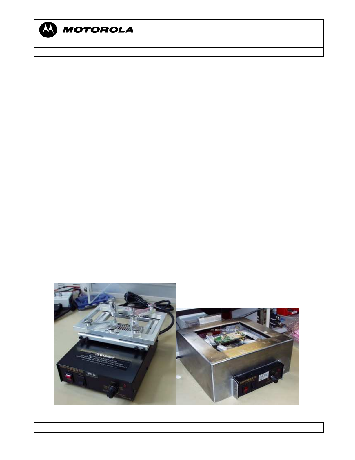
- Advice on working with lead free soldering/underfilm
- Use lead free flux
- Use preheater(HAKKO 853)
- Use tool for resolder (PA and U250), part no 19500950 (Pre soldering Fixture)
-
part no 99991966 (Metal stencil GSM Edge)
part no 19501966 (Mounting Bracket GSM
Edge)
part no 99991964 (Metal stencil for PA)
part no 19501964 (Mounting bracket for PA)
Use of preheater
Page 4
Motorola GmbH, CSS Center, Mobile Devices
Doc. No: TSG_V3i/V3_05
Date: 04.09.2006
Title: Troubleshooting-Guide V3i / V3_05 Page: 4 / 22
Repair Support Information
© Copyright 2003-2006 Motorola Inc. All Rights reserved.
Motorola internal use
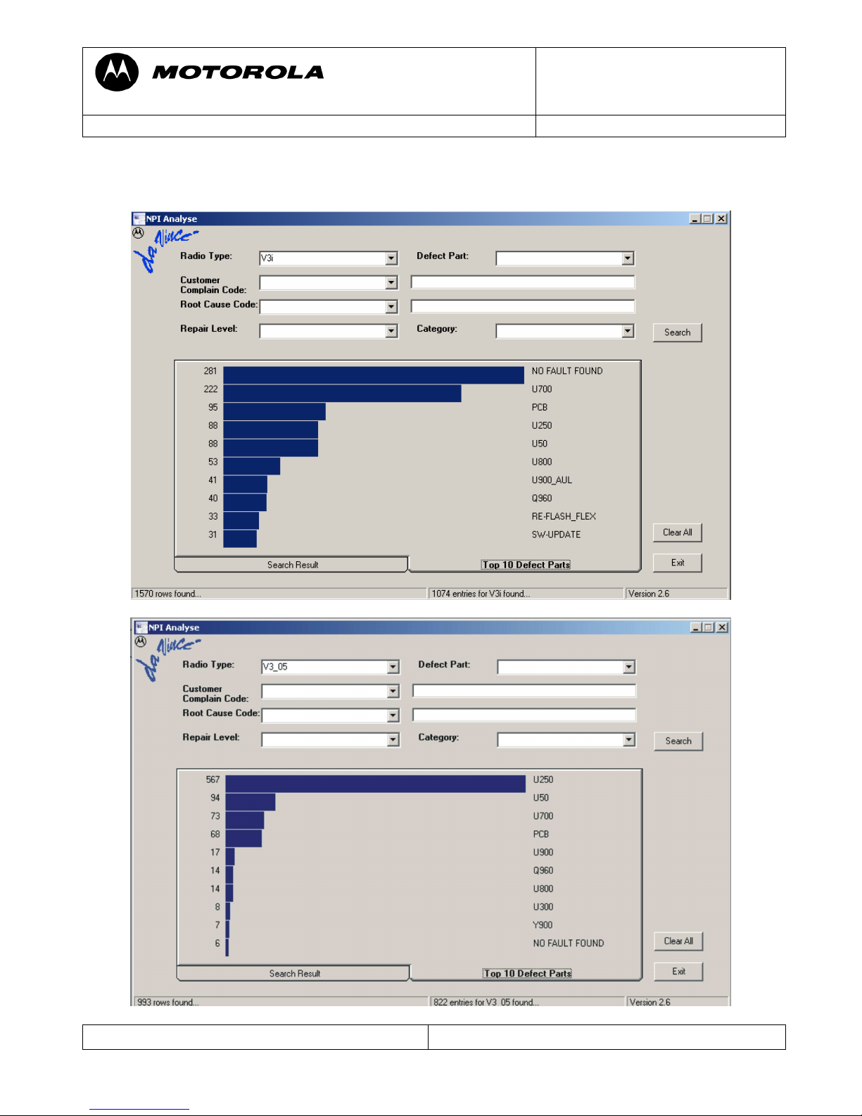
Top Ten defect parts
The following is an analysis summery of the V3i and V3_05 repaired during NPI process by
the Repair Entitlement Group CSS Flensburg
Page 5
Motorola GmbH, CSS Center, Mobile Devices
Doc. No: TSG_V3i/V3_05
Date: 04.09.2006
Title: Troubleshooting-Guide V3i / V3_05 Page: 5 / 22
Repair Support Information
© Copyright 2003-2006 Motorola Inc. All Rights reserved.
Motorola internal use
Troubleshooting Guide
First Step
Please make sure beforehand, that the problem at hand is not a SW related issue that can be
solved with a 1FF update and a Master Reset/Clear. In many cases a simple Master Reset can
already fix the problem.
The following section is meant to be a help in troubleshooting problems which are already
Identified as PCB related
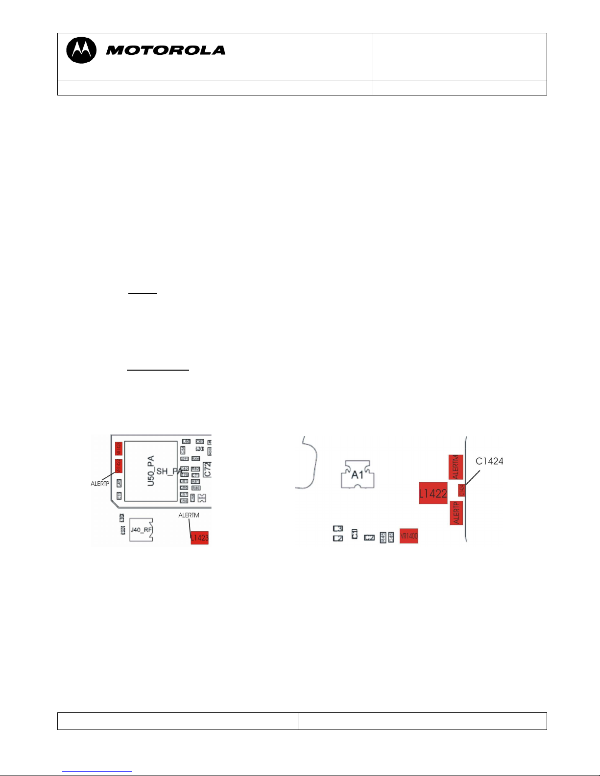
ALT01 Alert – Ring tone, no
ALT02 Alert – Ring tone, low
ALT03 Alert – Ring tone, noise/distortion
Check ALERTP and ALERTM -- both should have around 2.1Vdc
- If not
check L1422/L1423/ for broken connection,C1424 for low resistance
VR1400/VR1422/VR1423 for shortcut to ground
- check PCB for open tracks from ALERTM to U900-V10 /ALERTP to U900-U8
- you can either use“Repair-Studio” to switch on 1 kHz tone to the alert to check for
open tracks, but be careful: You can have 1 kHz and audio in call at
ALERTM/ALERTP, but no alert-tone, because the ATLAS is defect!
if 1kHz is ok, replace Atlas (U900). Please use underfilm for U900.
The alert signal is converted to analog and amplified by the ATLAS, but generated by the
Neptune, so if the ATLAS alert audio path is ok there could be a problem with the
Neptune not generating the alert signal.
ALT11 Alert – Vibrator, no
ALT12 Alert – Vibrator, weak
Turn on vibrator using Repair Studio/ Radiocomm. Measure V_VIB – should be about
2Vdc.V_VIB is provided directly by the ATLAS (U900).To verify if the vibrator is defective
a simple method is to provide a supply voltage (1Vdc should be enough) via test probes
directly on the vibrator G1 (radio in off state!).It should be rotating, if not replace the vibrator
G1.Check the diode D_VIB . Otherwise replace ATLAS (U900). Please use underfilm for
U900.
Page 6
Motorola GmbH, CSS Center, Mobile Devices
Doc. No: TSG_V3i/V3_05
Date: 04.09.2006
Title: Troubleshooting-Guide V3i / V3_05 Page: 6 / 22
Repair Support Information
© Copyright 2003-2006 Motorola Inc. All Rights reserved.
Motorola internal use
Vibrator G1
D_VIB
V_VIB
ac tive:2 V
from ATLAS
GND
AUDxx Audio problems
First step on every audio related problem is to identify which audio paths are affected. If the
audio signals in a loop are ok, there could be an audio problem in a network call. This could
be due to an ATLAS or Neptune related defect.
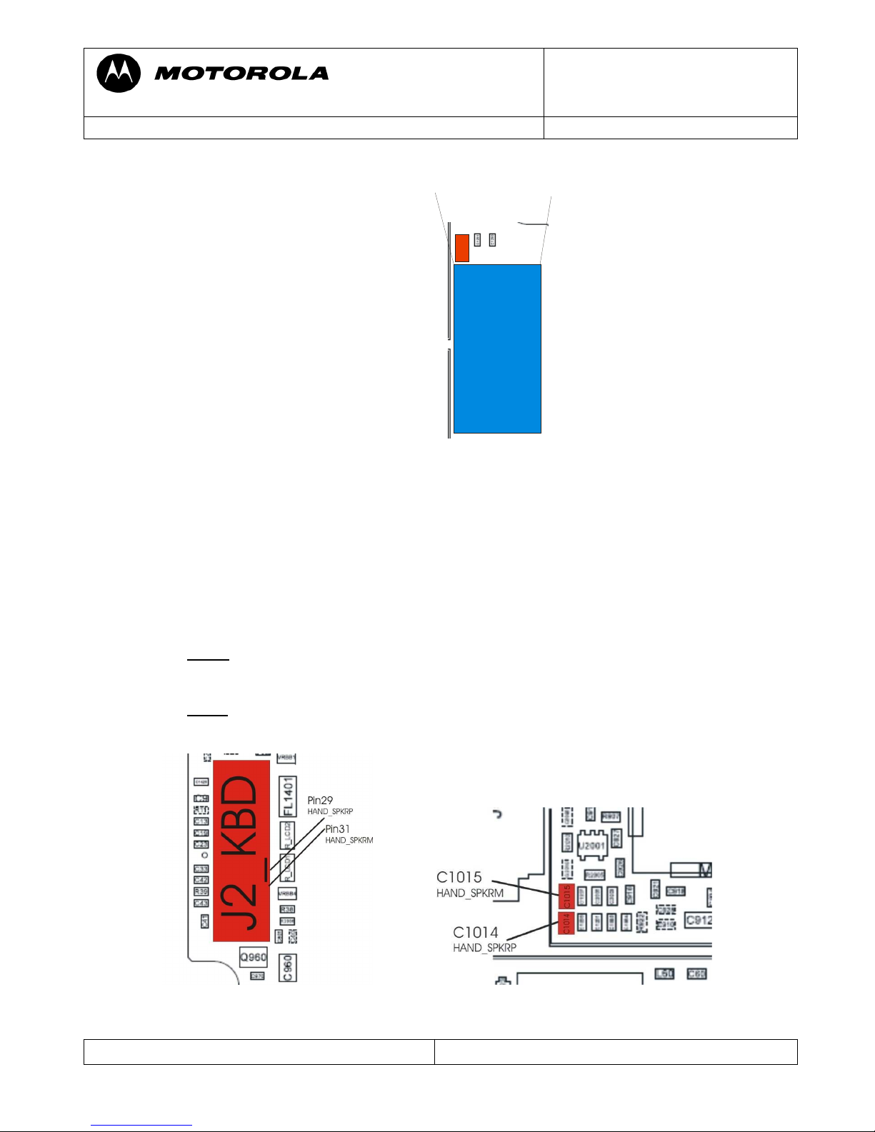
AUD01 Audio – Earpiece, no
AUD02 Audio – Earpiece, low
Check HAND_SPKRM at C1014 and HAND_SPKRP at C1015. Both should have around
1.4Vdc offset voltage, if audio-loop is switched on and additional up to 2,7Vpp at 1 kHz, if
test-tone is switched on.
- If not check J2 for solder shorts,C1014/1015 for low resistance
- (eventually) check PCB on open tracks from J2 to C1014/U900-T6 and J2 to
C1015/U900-R7
- If ok, replace Atlas (U900). Please use underfilm for U900.
Page 7
Motorola GmbH, CSS Center, Mobile Devices
Doc. No: TSG_V3i/V3_05
Date: 04.09.2006
Title: Troubleshooting-Guide V3i / V3_05 Page: 7 / 22
Repair Support Information
© Copyright 2003-2006 Motorola Inc. All Rights reserved.
Motorola internal use
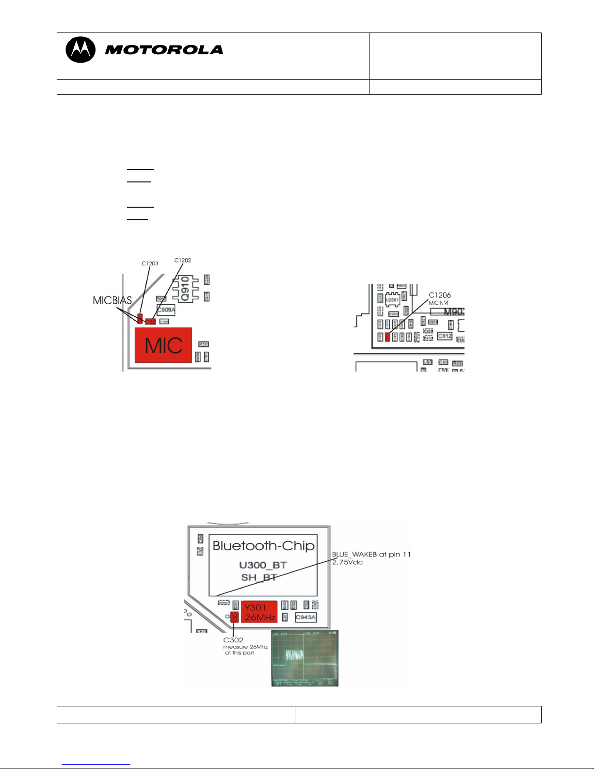
AUD07 Audio – MIC, No
AUD08 Audio – MIC, Low
Set radio in audio loop using Repair Studio/Radiocomm
- check MIC BIAS1 at C1207 – should be around 1,75Vdc
- if not
check C1207/1206/1201/1202/1200/1203 for low resistance
- if ok check MIC_IN_M at C1206 while blowing into the microphone to see the
audio signal caused by the blowing
- if not replace microphone
- if ok replace ATLAS (U900) Please use underfilm for U900.
ACC07 -- Accessory - Bluetooth module, no Operation
Verify it Bluetooth can be activated and is able to find other Bluetooth devices.
- If not, check oscillator Y301 (26MHz).
- check the BLUE_WAKEB
- replace U300
- If not, replace Neptune (U800)
Note: You can only measure the signals, when Bluetooth is activated.
pulsed signal
Page 8

Motorola GmbH, CSS Center, Mobile Devices
Doc. No: TSG_V3i/V3_05
Date: 04.09.2006
Title: Troubleshooting-Guide V3i / V3_05 Page: 8 / 22
Repair Support Information
© Copyright 2003-2006 Motorola Inc. All Rights reserved.
Motorola internal use
BAT02 – Battery life short
BAT03 – Battery cant turn on phone
CHGxx -Charging problems
TON01 – No Turn On (draws high current)
In probably most cases these problems are caused by an off current. First verify whether there
is an off current. If there is an off current, it should be checked whether the device draws
current via battery and/or via external connector.
In case of an off current via battery there should be a low resistance (less than ~200 Ohm)/ or
a short from BATT_P (J2-Batt) to GND.
To localize the defective part causing the short/ low resistance a simple way is to freeze the
board with a coolant-spray, supply a battery voltage from a power supply using micro clamptype test probes, and see which parts are getting warm. This is a very basic and essential
method to troubleshoot off current / high current consumption failures.
The power supply (for BATT_P) should be set to 3,7V with current limitation to 2A.We
strictly recommend using the Power Supply Unit Current Drain Meter to check the current
drain of the PCB.
Shields covering suspected parts should be removed before freezing the PCB.
The PCB should be handled with care. After removing the shields the PCB should be given
some time to cool down slowly before freezing it to far below zero to avoid physical stress to
the multilayer PCB with lead soldered parts.
In some cases the part, which is getting warm has an internal short itself. After removing this
part the off current should be fixed. For verification check off current or measure resistance
BATT_P (J2-Batt) to GND.A new part can be placed.
If the short / low resistance remains after replacing the part which getting warm, it should be
checked which signals / voltages this part provides. In the most cases this part will provide a
supply voltage to other parts which can also get warm due to an internal short.
Page 9

Motorola GmbH, CSS Center, Mobile Devices
Doc. No: TSG_V3i/V3_05
Date: 04.09.2006
Title: Troubleshooting-Guide V3i / V3_05 Page: 9 / 22
Repair Support Information
© Copyright 2003-2006 Motorola Inc. All Rights reserved.
Motorola internal use
To find out a defective part an easy way is to use the Flensburg Layout Viewer to follow the
signal (check for SHORT_RESISTORS after which the signals possibly could have a changed
name), and remove the parts one after another, until the short is gone.
Most frequent parts with internal shorts causing these kinds of failures are the PA (U50), the
ATLAS /U900), the Q960, and the Neptune (U800)
1. Example:
- BAT00 -- radio draws about 250mA in standby, no off current
- U900 are getting warm
- U900 provides BR 3,85V for PA (using Flensburg Layout Viewer)
- GSM-PA is also getting warm (see below)
- U50 itself has an internal short
Defective U50
2. Example:
- BAT02—radio draws about 40mA off current
- Only ATLAS is getting warm (checked with coolant-spray); nothing else
- ATLAS draws off current-> replace ATLAS. Please use underfilm for U900.
Page 10

Motorola GmbH, CSS Center, Mobile Devices
Doc. No: TSG_V3i/V3_05
Date: 04.09.2006
Title: Troubleshooting-Guide V3i / V3_05 Page: 10 / 22
Repair Support Information
© Copyright 2003-2006 Motorola Inc. All Rights reserved.
Motorola internal use
BAT04 – Invalid Battery
- Verify OWB (J3_BATT-2) while PCB is connected to EMU_USB cable. It should be
2.775V.Check also J3 for broken part.
- If it is low, check D1426 and R1200 (4,7k).
- If they are ok check U250 inform to make U250 cold with coolant-spray.U250 could
have internal interruptions at product code 03/06 to 27/06!!!!
- If the voltage OWB stays low, it should be a problem with the Neptune (U800).
CHG01 – Does not charge
If the phone seems to charge, but battery meter stays at low level, check whether there is a
high current consumption or an off current via battery. If so please follow troubleshooting as
described in the BATxx section of this document.
If there no off current, check the whole path for the charging current. Make a battery/charger
phasing to see, if only the charger current or also the battery-phasing is affected. For a charger
current problem only:
Check Q903, Q904, Q905, Q906, R904, R905, R910, J3 for broken contact
if ok replaces ATLAS (U900). Please use underfilm for U900.
For additional battery phasing problems (for example: battery sense or battery meter) replace
ATLAS (U900)
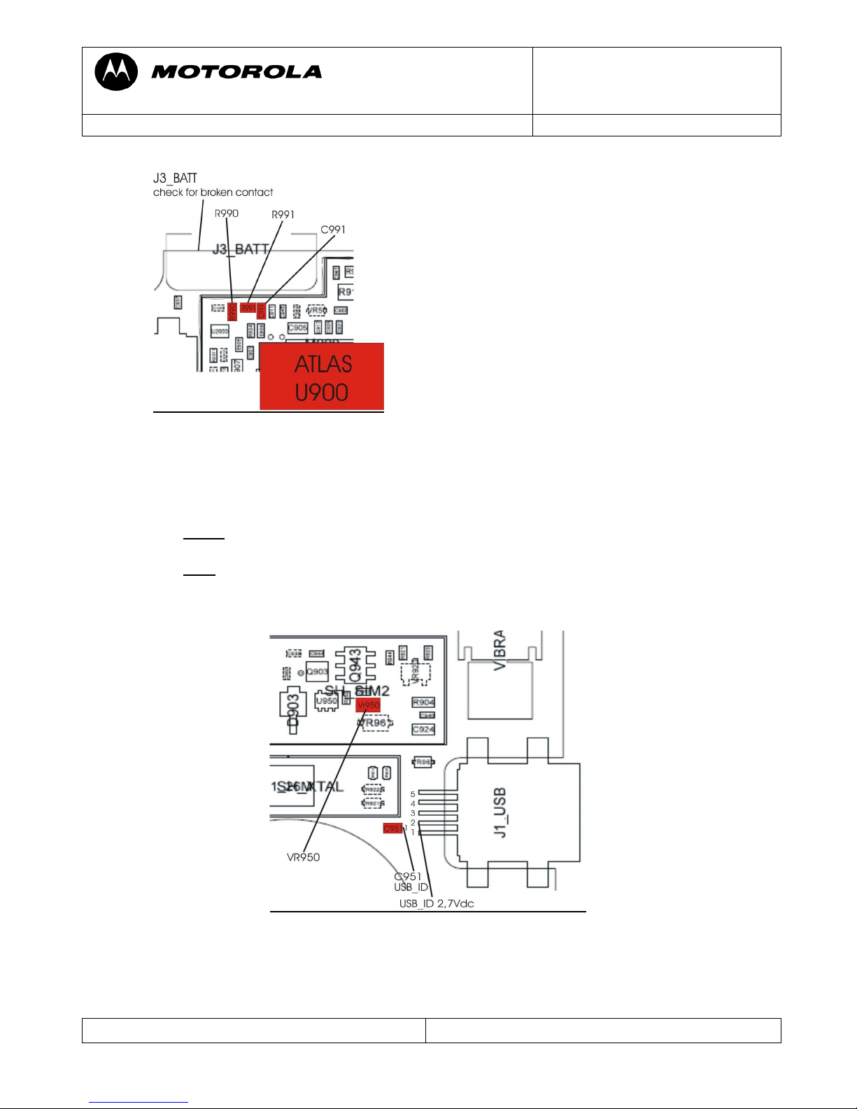
Battery Thermistor problem
Check BATT_Therm at J3-3, it should be 2,7Vdc.If it is not check R990, R991 and C990 for
low resistance.
If ok
replace the ATLAS (U900) .Please use underfilm for U900
Page 11
Motorola GmbH, CSS Center, Mobile Devices
Doc. No: TSG_V3i/V3_05
Date: 04.09.2006
Title: Troubleshooting-Guide V3i / V3_05 Page: 11 / 22
Repair Support Information
© Copyright 2003-2006 Motorola Inc. All Rights reserved.
Motorola internal use
CHG02 – No charging indication
If display indicates“Charging not possible” or the phone powers on while plugging in the
charger, but is not charging. Then check the USB_ID line at J1_USB-2 with phone
powered on by battery. It should be 2, 7Vdc (2,4Vdc is not enough!)
- If not check VR950.USB_ID voltage must be 2,7Vdc,if VR950 is removed
- Check voltage at C951-1 (2,7Vdc)
- If ok replace the ATLAS (U900) because the EMU-chip is in ATLAS integrated.
Please use underfilm for U900.
CPR01 – Voice call – Can’t make
CPR02 – Voice call – Can’t receive call
CPR03 – Voice call – no service
Page 12

Motorola GmbH, CSS Center, Mobile Devices
Doc. No: TSG_V3i/V3_05
Date: 04.09.2006
Title: Troubleshooting-Guide V3i / V3_05 Page: 12 / 22
Repair Support Information
© Copyright 2003-2006 Motorola Inc. All Rights reserved.
Motorola internal use
First step in every Call related problem should be to figure out whether there is a receiving
problem or a transmitting problem and which bands are affected.
Make sure, that the RF connector (J40_RF) is cleaned (with cleaner or alcohol) before making
a phasing/call-processing test or if the test fails!
No TX GSM900 (850/1800/1900)
Let radio transmit on GSM900 using Repair Studio/Radiocomm.
- Check RF_OUT_1 at C15
- If ok
in size and form (if unsure compare to good radio) check J40
If the power is only a few dB below at J40, then follow the repair-steps.
- if TX at J40 is not ok check PA input (LB_TX_IN) at C57
- if TX_EN_IN is good, following signals should be present:
- BP_3,75Vdc at C72
- RF_OUT_1
- If RF_OUT_1 is not ok, then change PA (U50)
- If TX_EN_IN was not present, change U250_SYNTH
Important!! U250 could have internal interruptions at product code 03/06 to 27/06.
No RX GSM900 (850/1800/1900)
Inject a RF from Test Set. Check RF_OUT_1 at C15.
There no other test points to measure the RX-signal, because the signals are directly go to
U250_SYNTH.
So you can only check the signals from U250_SYNTH.
- VCO_REG at C155
- RF_REG at C154
- PERIPH_IO_REG at C227
- RF_REG at C151
- RX850 at R50
Many TX-RX failures are problems with U250_SYNTH.
Page 13

Motorola GmbH, CSS Center, Mobile Devices
Doc. No: TSG_V3i/V3_05
Date: 04.09.2006
Title: Troubleshooting-Guide V3i / V3_05 Page: 13 / 22
Repair Support Information
© Copyright 2003-2006 Motorola Inc. All Rights reserved.
Motorola internal use
To change U250 you should work with the tool for resolder.
Important!!U250 could have internal interruptions at product code 03/06 to 27/06.
Note: For AFC phasing the receiver is used.So, if there is any RX fail, the AFC phasing
on that frequency band also fails. If the RX phasing is kobo only AFC phasing fails, a bad
crystal is most likely cause.
- replace Y201
DAP11 – Data Application – cannot upgrade software
OPR03 – Operation – Error Message
Make sure, that you have adjusted 5Vdc on your power supply for the EMU-cable.
Watch the display when entering the flash-mode. If an error message appears, do
following action:
- for “corrupt code error”: make a Reflash, when failed Flash (U700) is defect
- for “code SEG error”: Flash (U700) is defect. A reflash is not successful!
Otherwise go to the TONxx section on this document.
DIM01 -- Display Main – no display
DIM08 – Display Main – no backlight
DIM09 – Display Main – Low/Dim backlight
DIS01 – Display Secondary – no display
DIS07 – Display Secondary – no backlight
DIS08 – Display Secondary – Low/Dim backlight
DAP10 – Data Application – poor picture quality
Make sure that the problem is not located in the Flip Assembly, by testing PCB with a
good one and do an optical check of J2_KBD.
Make a reflash /flex with a 1FF-File at first.
Page 14

Motorola GmbH, CSS Center, Mobile Devices
Doc. No: TSG_V3i/V3_05
Date: 04.09.2006
Title: Troubleshooting-Guide V3i / V3_05 Page: 14 / 22
Repair Support Information
© Copyright 2003-2006 Motorola Inc. All Rights reserved.
Motorola internal use
The following supply voltages for the Flip Assembly should be present:
- ATI_RESETB_2,7V at C801
- V_BOOST_5V at C 936
- REG_3V at C33
- CLK_32KHZ_2_7V at CLK_32KHZ_2_7V-1
- VBUCK_FLIP_1,875V at C970
- VBUS _5V at C13
The voltages can be ok without a flip connected, but can break down, if a flip is plugged
in, although the flip is ok!
If ok
check:
- Q960 for broken part
- IO_REG_2,7Vdc at C830 generated by Q960
- VRBB 4 for broken part
- R_LCD 1-6 solder short
- R_LCD 2-6 solder short
- U 1401 for defective part
If all of these are ok, it should most likely be a problem with Neptune (U800)
Page 15
Motorola GmbH, CSS Center, Mobile Devices
Doc. No: TSG_V3i/V3_05
Date: 04.09.2006
Title: Troubleshooting-Guide V3i / V3_05 Page: 15 / 22
Repair Support Information
© Copyright 2003-2006 Motorola Inc. All Rights reserved.
Motorola internal use
DIM01 – Display Main – no display
MKP01 – Main Keypad – no Function/hangs
TON01 – Turn on/off – No turn on
Make a reflash /flex with a 1FF-File at first.
Flip detect problem
Units with a flip detect problem will show following symptoms:
- no power on via battery
- no main display via EMU connector supply
- CLI display is not switching on open/close flip
- No keypad function
Check PERIPH_IO_REG at U1401-5 – should be 2,7Vdc (High)
- check HS_INT at U1401-4 – should be 2,7Vdc,when flip is closed
If ok
, replace Neptune (U800)
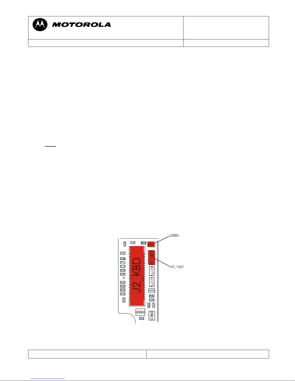
MKP01 – Main Keypad - no function/hangs
SIK01 – Side Keys – no function
Due to the keypad matrix architecture with 8 rows in 4 columns it is quite useful to verify
which keys (if not all) are affected. By knowing which keys are not working, it is possible to
find out which row or column is affected. You can either use Ohm Meter to check the
resistance to GND for verification, which line is affected. By using the FL Viewer it can be
tracked which filters the signal passes until it reaches the Neptune.
Check:
- FL 1401
- VRBB1
- J2_KBD for loose pins or solder short
If the keypad connector/Filters are ok it’s probably a problem with the Neptune (U800).
Page 16
Motorola GmbH, CSS Center, Mobile Devices
Doc. No: TSG_V3i/V3_05
Date: 04.09.2006
Title: Troubleshooting-Guide V3i / V3_05 Page: 16 / 22
Repair Support Information
© Copyright 2003-2006 Motorola Inc. All Rights reserved.
Motorola internal use
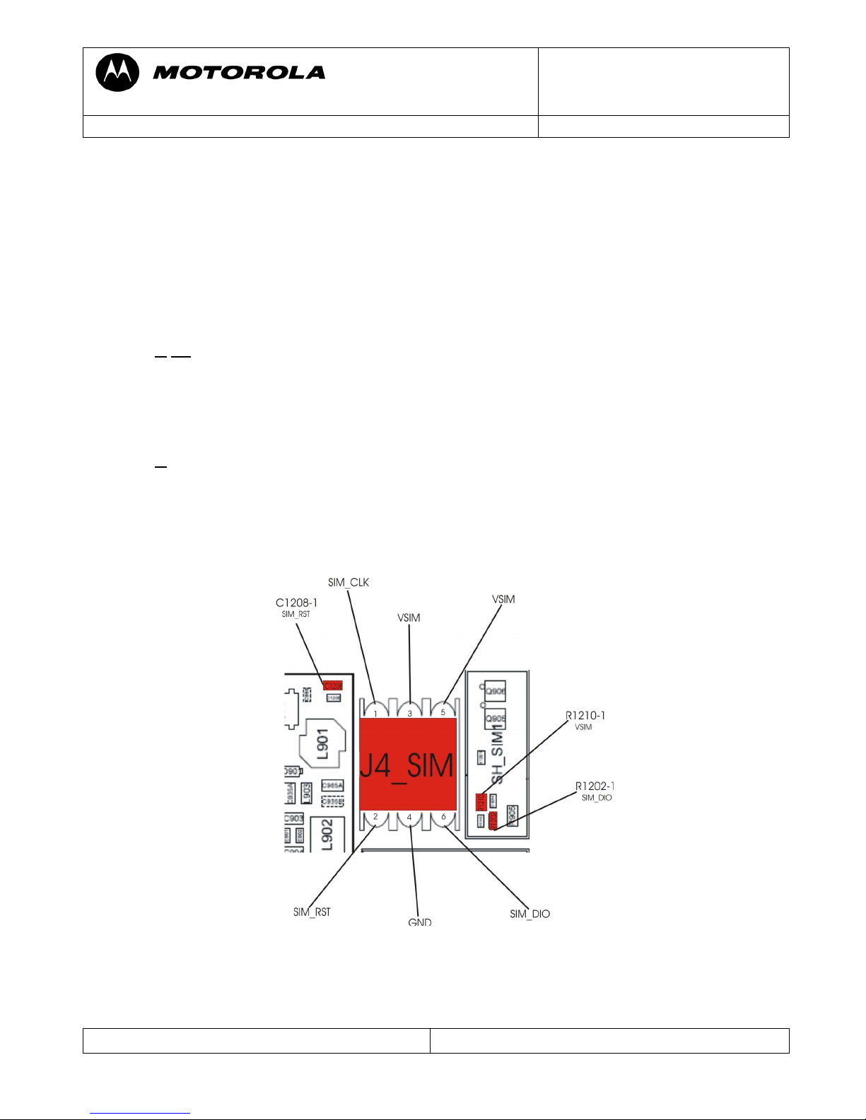
SIM01 – Sim card – check card/insert SIM
The most problems of V3i SIM card are caused by a tombstoned part R 805 near Neptune.
Measurement on the SIM interface is a little bit difficult, as not all signals will be present until
a SIM card and a battery are inserted. As far as I know there is still no SIM feature
implementation in Repair Studio or Radiocomm. In the most cases it should be possible to
figure out which part is defective by simply using the Ohm Meter to measure the following
signals to GND:
- VSIM at E 909-1, C 828-1
If
far less then 30 kOhm to GND, it could be a defective ATLAS (U900)
- SIM_DIO at R 1210-2,VR 1412-1
- SIM_RST at R 805-2,C 1208-2
- SIM_CLK at R1201-1
If any of these has far less then 30 kOhm to GND, it could be a defective Neptune (U800).
Before replacing the Atlas (U900) or the Neptune (U800) make sure that none of the
associated capacitors or resistors has low resistance to GND.
The VSIM can also be checked with the oscilloscope. First put the probe to the test point
(C828-1) and then switch on the phone (by switching the output of the power supply).
After a few seconds the VSIM (2,7Vdc) should appear for about one second.
Page 17
Motorola GmbH, CSS Center, Mobile Devices
Doc. No: TSG_V3i/V3_05
Date: 04.09.2006
Title: Troubleshooting-Guide V3i / V3_05 Page: 17 / 22
Repair Support Information
© Copyright 2003-2006 Motorola Inc. All Rights reserved.
Motorola internal use
TON01 – No Turn On
Verify if radio doesn’t turn on (assembled with display). If it does, but doesn’t enumerate
via EMU-Connector at RSD/Repair Studio there should be a problem with the USB
connection. In some cases a 1FF SW reflash in FORCED FLASH MODE (by connecting
EMU Connector to radio while “*” and “#” are pressed) can fix the issue.
- If not
, visually check EMU Connector for mechanical defects or contamination on
contacts, bad soldered pins or solder shorts.
- Check the DP_RXD line at VR921A-1 (J1_USB-3) and DM_TXD line at VR922A-1
(J1_USB-4) with an Ohm Meter to GND to make sure, that there is no short to GND
or an open track.
- Check VR 921A, VR922A,R920 and R921 for high resistance
- If ok replace ATLAS ( U900). Please use underfilm for U900.
- If not ok, replace Neptune ( U800)
The USB interface is located in the Neptune, but the data bus is switched through by the
EMU-chip (EMU-chip was integrated in U900)
If the radio doesn’t turn on, but draws high current (>500mA)
- Please follow troubleshooting instructions as described in the BATxx section of this
document.
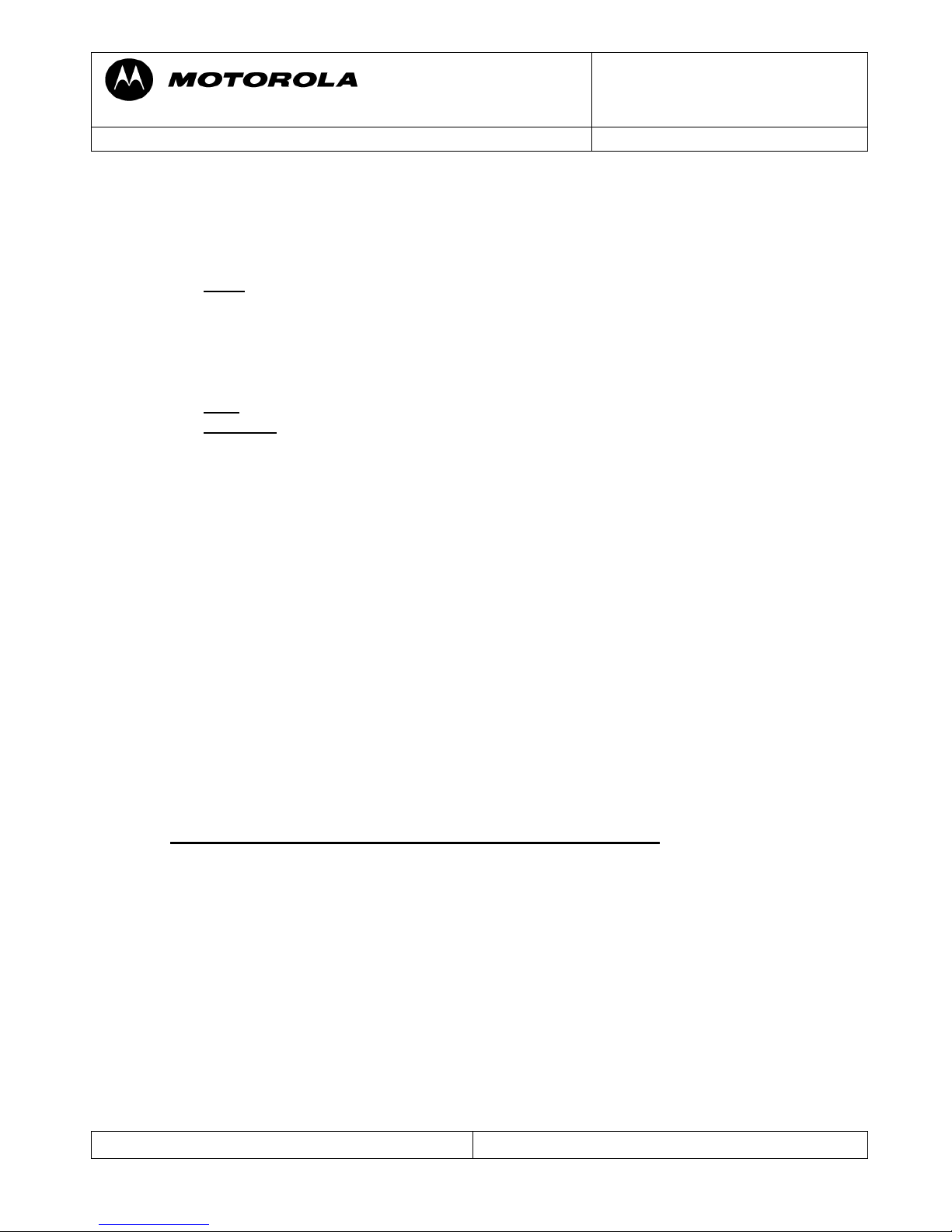
Note:
- Watchdog
In case the phone draws current but switches off after a few seconds, you can force the
phone not to switch off, by setting the Watchdog C902.By just solder across C 902-1 and
C 947-1 (PERIPH_IO_REG 2,775Vdc) the WATCHDOG signal will be pulled to HIGH
(PERIPH_IO_REG 2,775Vdc) and the ATLAS will not switch off its power regulators.
You will then be able to measure all the voltages or to do a thermal troubleshooting by
using coolant-spray.
Note:
Make sure to remove solder short after repair!!!!
- “power switch”
The second way to check the voltages is to use a switch in the plus line of your power
supply. You can put the probe to the test points of each voltage and view the voltages
appearing for a short time (half a second) during each switching action.
Page 18
Motorola GmbH, CSS Center, Mobile Devices
Doc. No: TSG_V3i/V3_05
Date: 04.09.2006
Title: Troubleshooting-Guide V3i / V3_05 Page: 18 / 22
Repair Support Information
© Copyright 2003-2006 Motorola Inc. All Rights reserved.
Motorola internal use
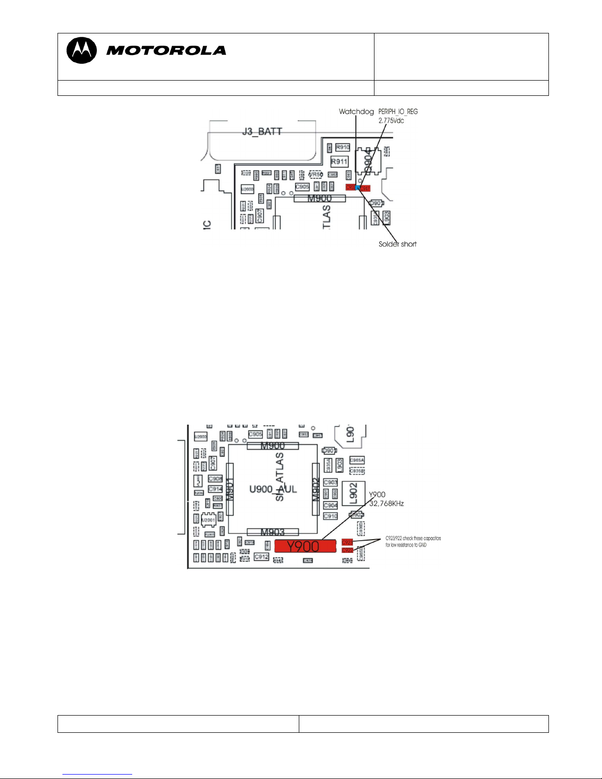
If radio draws no current at all (also not for a short time) it’s most likely a problem with
the 32.768 KHz clock generated by Y900
- replace Crystal Y900
- If unsuccessful, replace ATLAS ( U900). Please use underfilm for U900.
Note:
If the current drain is in normal range (40mA to 230mA) but cannot connect to
Repair Studio/RSDlite (USB device error) then look at U250 for product code (
03/06 to 27/06), or use coolant spray to freeze U250. If the phone connects to Repair
Studio/ RSDlite then replace U250.
Page 19

Motorola GmbH, CSS Center, Mobile Devices
Doc. No: TSG_V3i/V3_05
Date: 04.09.2006
Title: Troubleshooting-Guide V3i / V3_05 Page: 19 / 22
Repair Support Information
© Copyright 2003-2006 Motorola Inc. All Rights reserved.
Motorola internal use
If the current consumption is in normal range (40mA to 230mA)
- Try doing a 1FF SW reflash in FORCED FLASH MODE. If radio enters the forced
flash mode or starts in flashmode by itself the main supply voltages for the logic
section should be ok – Most likely the trouble can be found in the logic section
(Neptune/Flash).
For “critical error xx xx” go to the DAPxx
section of this document.
- If unsuccessful, a flash log file generated by Repair Studio/RSD can be viewed.
There
You will find the reason for the flash operation failure. However, this information can
be ignored, as in almost every case the next steps will be
- replacing Flash U700
- replace Neptune U800
- replace ATLAS U900
If the phone enters flash mode by itself as “S Blank Neptune” at Repair Studio/RSDlite,
The Neptune cannot recognize any flash:
- freeze U250 with coolant spray, if it is starting up now, then change U250
- replace Flash ( U700) – if unsuccessful additionally
- replace Neptune ( U800)
TON03 – Turn on/off – auto power down in standby
If phone stores panic: DSM_MEASUREMENT_ERROR there is most properly a problem
with the 32.768 KHz clock, which is needed for the whole radio when in deep sleep mode.
Replace Y900, test radio with a network SIM card and let radio enter deep sleep mode.
- if radio still powers down, replace ATLAS ( U900)
Follow up faults caused by failed repair actions
Quite a lot of repairs which were sent to Level 4 service have a second fault, which is caused
by an unsuccessful repair attempt.
We strictly recommend to a visually check the PCB for skewed or tombstone parts, solder
shorts or heat bubbles in PCB after every soldering action. Especially small parts which are
located close to shields can easily be misplaced during removal or setting of the shields.
We found that some parts seem to be more heat sensitive then others.U250, U300 and the
MIC are heat sensitive.
Also we found many badly reworked PA’s (U50).
Please use the tool for resolder the PA, also for U250.
Page 20
Motorola GmbH, CSS Center, Mobile Devices
Doc. No: TSG_V3i/V3_05
Date: 04.09.2006
Title: Troubleshooting-Guide V3i / V3_05 Page: 20 / 22
Repair Support Information
© Copyright 2003-2006 Motorola Inc. All Rights reserved.
Motorola internal use
The key-differences between V3i and V3_05 are:
- no external card reader on V3_05
- no RTC battery on PCB for V3_05, is integrated in Flip
- another Bluetooth – Chip on PCB
- for V3_05 was Class 1, Partnr. 4888735Y01
- for V3i was Class 2, Partnr. 5189447N02
Page 21

Motorola GmbH, CSS Center, Mobile Devices
Doc. No: TSG_V3i/V3_05
Date: 04.09.2006
Title: Troubleshooting-Guide V3i / V3_05 Page: 21 / 22
Repair Support Information
© Copyright 2003-2006 Motorola Inc. All Rights reserved.
Motorola internal use
Flash procedures for V3i
Note: To using all 1FF files phone switch only in Flashmode when a Display is connected.
Note: It is very important to do a restart after every flash process! Otherwise the phone will
start up in flash mode again.
Software update
Following steps are necessary to update the Software to the latest approved Software:
- unlock phone ( if subsidy locked)
- flash customer specific 1FF superfile (example: DC One File Flash:
R479_G_08.B4.85R_PDS005_LP0039_DRM0101_VSTGERMAN206_JPJAVA_G_08_V3I_06_00_03R_SE7721AXXF10
CF_1FF.SBF
- after restart:
- take out of “ in Factory” – if necessary
- perform a Master Reset/Master Clear
Recovering Flash Memory in Forced Flash Mode
If the phone doesn’t start because of corrupted software it might be possible to recover it:
- connect phone to EMU – cable while pressing “*” and “#”
The phone should start in flash mode now: S Flash Neptune
- flash1FFsuperfile(example:DCOneFileFlash:
R479_G_08.B4.85R_PDS005_LP0039_DRM0101_VSTGERMAN206_JPJAVA_G_08_V3I_06_00_03R_SE7721AXXF10
CF_1FF.SBF
- after restart:
- perform a Master Reset/Master Clear
If the phone doesn’t start in flash mode or as: S Blank Rainbow Neptune, there is a problem.
Please follow the troubleshooting instructions as described in the TON01 section of the
Troubleshooting-Guide.
Image flash
Following steps are necessary to flash a phone with blank (new) flash memory:
- connect phone to EMU-cable
- phone will start in flash mode as S Blank Neptune
- flash image file ( example: image file:
R 479_G-08.B4.2AI_GNPO_2_RFDI_LP0003_DRM0101_GMPSLQA000AA03B_image
- after restart:
- write and save Primary Subsidy, Secondary Subsidy and Service Password
- write and save IMEI
- write and save Serial Number and Bluetooth- address
- upgrade: flash latest approved costumer software as 1FF file
- after restart:
- take out of “In Factory”
- perform a Master Reset/Master Clear
- do a complete phasing/call processing
Page 22

Motorola GmbH, CSS Center, Mobile Devices
Doc. No: TSG_V3i/V3_05
Date: 04.09.2006
Title: Troubleshooting-Guide V3i / V3_05 Page: 22 / 22
Repair Support Information
© Copyright 2003-2006 Motorola Inc. All Rights reserved.
Motorola internal use
Flash procedures for V3_05
Note: To using all 1FF files phone switch only in Flashmode when a Display is connected!
Note: It is very important to do a restart after every flash process! Otherwise the phone will
start up in flash mode again.
Software update
Following steps are necessary to update the Software to latest approved Software:
- unlock phone ( if subsidy locked)
- flash customer specific 1FF superfile (example: DC One File Flash:
R4515_G_08.BD.43R_PDS005_LP0039_DRM0101_JPJAVA_G_08_R4515_06_00_02R_SE6770AXXF1081_1FF.S
BF
- after restart:
- take out of “ in Factory” – if necessary
- do Master Reset/Master Clear
Recovering Flash Memory in Forced Flash Mode
If the phone doesn’t start because of corrupted software it might be possible to recover it:
- connect phone to EMU – cable while pressing “*” and “#”
The phone should start in flash mode now: S Flash Neptune
- flash1FFsuperfile(example:DCOneFileFlash:
R4515_G_08.BD.43R_PDS005_LP0039_DRM0101_JPJAVA_G_08_R4515_06_00_02R_SE6770AXXF1081_1FF.S
BF
- after restart:
- do Master Reset/Master Clear
If the phone doesn’t start in flash mode or as: S Blank Rainbow Neptune, there is a problem.
Please follow troubleshooting instructions as described in the TON01 section of the
Troubleshooting-Guide.
Image flash
Following steps are necessary to flash a phone with blank (new) flash memory:
- connect phone to EMU-cable
- phone will start in flash mode as S Blank Neptune
- flash image file ( example: image file:
R 4515_G-08.BD.22I_RFDI_LP0003_DRM0101_GMTV3xx050AA03F_image
- after restart:
- write and save Primary Subsidy, Secondary Subsidy and Service Password
- write and save IMEI
- write and save Serial Number and Bluetooth- address
- upgrade: flash latest approved costumer software as 1FF file
- after restart:
- take out of “In Factory”
- perform a Master Reset/Master Clear
- do a complete phasing/call processing
 Loading...