

Page 1
V.3600
Modem User’s Guide
NO
YES
CS
Motorola ISG Part No. T0097, B
20 Cabot Boulevard Model V.3600
Mansfield, Massachusetts 02048 February, 1999
USA © 1998 Motorola
TALK/DATA
RD
TD
CdTR
RS
V.3600
Page 2

Copyright
Copyright 1998 Motorola Inc.
Published by Motorola, who reserves the right to make improvements in
the products described in this manual as well as to revise this
publication at any time and without notice to any person of such
revision or change. All rights reserved. No part of this public ation may
be reproduced, transcribed, stored in an electronic retrieval system,
translated into any language or computer language, or be tran sm itted in
any form whatsoever without the prior written consent of the publisher.
For additional information contact:
Motorola ISG, Inc.
20 Cabot Boulevard
Mansfield, Massachusetts 02048
USA
Trademarks
and Motorola are registered trademarks of Motorola, Inc.
The following are trademarks or registered trademarks of their
respective companies or organizations.
Product Company/Organization
MNP Microcom Incorporated
Notice
All titles, versions, trademarks, claims of compatibility, etc., of
hardware and software pr oducts mentioned herein are the sole property
and responsibility of the respective vendors. Motorola makes no
endorsement of any particular product for any purpose, nor claims
responsibility for its operation and accuracy.
Updates
Check Motorola Web sites as listed under “Service and Support” at the
end of this User’s Guide for the latest updates to our products.
ii V.3600
Page 3

Regulatory Information
FCC Requirements
This equipment complies with FCC rules Part 68. Located on the
equipment is the FCC Registration Number and Ringer Equivalence
Number (REN). You must provide this information to the telephone
company if requested.
The Registration Number and REN is inscribed on the printed circuit
board on insert cards, or on a label attached to either th e chassis bo ttom or
metal end-plate on standalone or rack models. The FCC requires that these
numbers be prominently displayed on an outsi de s urfa ce of t h e equi p ment .
The REN is used to determine the number of devices you may legally
connect to your telephone line. In most areas, the sum of the REN of all
devices connected to one line must not exceed five (5.0). Contact your
telephone company to determine the maximum REN for your calling area.
A variety of Universal Service Ordering Code (USOC) telephone wall
jacks are available for different types of devices or services. The USOC
jack required for this unit is RJ11/RJ41S/JM8.
The telephone company may change technical operations or procedures
affecting your equipment. You will be notified of changes in advance to
give you ample time to maintain uninterrupted telephone service.
If you experience trouble with this telephone equipment, please contact
Motorola
20 Cabot Boulevard
Mansfield, Massachusetts 02048
Telephone (800) 544-0062
for information on obtaining service or repairs. The telephone company
may ask that you disconnect this equipment from the network until the
problem has been resolved. If your equipment conti nu es to disrup t th e
network the telephone company may temporarily disconnect service. If
this occurs you will be informed of your right to file a complaint with the
FCC.
V.3600 iii
Page 4

Regulatory Information
This equipment may not be used on coin service provided by the
telephone company. Connection to party lines is subject to state tariffs.
An FCC compliant telephone cord and modular plug are provided with
this equipment, which is designed to connect to the telephone network
or premises wiring using a compatible modular jack that is Part 68
compliant. See installation instructions in Chapter 2, Installation for
details.
FCC Fax Branding Requirements
The Telephone Consumer Protection Act of 1991 makes it unlawful for
any person to use a computer or other electronic device to send any
message via a telephone, fax machine, or modem unless such message
clearly contains in a margin at the top or bottom of each transmitted
page or on the first page of the transmission, the date and time it is sent
and an identification of the business or other entity, or other individual
sending the message and the telephone number of the sending machine
or such business, other entity or individual.
Programming of this information is a function of the fax software which
runs on your computer. In order to program this information, please
consult the docu mentation provided with your fax software.
FCC Part 15 Declaration Of Conformity
FOR HOME OR OFFICE USE
Model Name:
V.3600, 115 VAC version only
Caution
This equipment uses, generates, and can radiate radio
frequency energy interf ering with radio communicat ions
if not installed and used according to the instruction
manual. It has been tested and complies with the limits
for a Class B computing device according to FCC Rules,
Part 15. Operation of this equipment in a residential area
may cause interference. If it does, you must correct the
cause of the interference.
Changes or modifications to this unit not expressly approved by the
party responsible for compliance could void the user’s authority to
operate the equipment.
iv V.3600
Page 5

Regulatory Information
Shielded Cables
This product has been tested and complies with FCC limits for a Class B
computing device. Testing was done with shielded computer cables
Using unshielded cables could cause your system to emit excess radio
frequency, increasing the chance of interference. To comply with FCC
regulations it is necessary to use shielded computer cables
installation.
FOR OFFICE USE ONLY
Model Name:
V.3600, all other versions
with your
.
Caution
This equipment uses, generates, and can radiate radio
frequency energy interfer ing with radio communication s
if not installed and used according to the instruction
manual. It has been tested and complies with the limits
for a Class A computing device according to FCC Rules,
Part 15. Operation of this equipment in a residential area
may cause interference. If it does, you must correct the
cause of the interference.
Changes or modifications to this unit not expressly approved by the
party responsible for compliance could void the user’s authority to
operate the equipment.
Shielded Cables
This product has been tested and complies with FCC limits for a Class A
computing device. Testing was done with shielded computer cables
Using unshielded cables could cause your system to emit excess radio
frequency, increasing the chance of interference. To comply with FCC
regulations it is necessary to use shielded computer cables
installation.
V.3600 v
with your
.
Page 6

Regulatory Information
Special Requirements For Canada
Certain requirements exist for data communication products
manufactured for use in Canada. Principle among these requirements is
the application of the IC label as described below. However , certain data
communication products do not require the IC label nor adherence to IC
requirements. If this is the case the IC label will not be affixed to the
units.
Industry Canada (IC) Requirements
IC labels are affixed to each unit sold in Canada. This label has the
certification number for that particular unit. The numbers are different
for each model.
The Industry Canada label identifies certified equipment. This
certification means that the equipment meets certain
telecommunications network protective, operational, and safety
requirements. IC does not guarantee the equipment will operate to the
user’s satisfaction.
Before installing this equipment, users should ensure that it is
permissible to be connected to the facilities of the local
telecommunications company. The equipment must also be installed
using an acceptable method of connection. In some cases, the company’s
inside wiring associated with a single line individual service may be
extended by means of a certified connector assembly (telephone
extension cord). The customer should be aware that compliance with the
above conditions may not prevent degradation of service in some
situations.
Repairs to certified equipment should be made by an authorized
Canadian maintenance facility designated by the supplier. Any repairs
or alterations made by the user to this equipment, or equ ip ment
malfunctions, may give the telecommunications company cause to
request the user to disconnect the equipment. For their own protection
users should ensure that the electrical ground connections of the power
utility, telephone lines and internal metallic water pipe system, if
present, are connected together. This precaution may be particularly
important in rural areas.
vi V.3600
Page 7

Regulatory Information
Caution: Users should not attempt to make install a tion connections
themselves, but should contact the appropriate electric inspection
authority or electrician.
Ringer Equivalence Number
The Ringer Equivalence Number (REN) assigned to each terminal
device provides an indication of the maximum number of terminals
allowed to be connected to a telephone interface. The termination on an
interface may consist of any combination of devices subject only to the
requirement that the sum of the Ringer Equivalence Numbers of all the
devices does not exceed five (5).
CANADIAN EMISSION REQUIREMENTS (V.3600, 115 Vac)
This Class B digital apparatus meets all requirements of the Canadian
Interference-Causing Equipment Regulations.
Cet appareil numérique de la classe B respecte toutes les exigences du
Règlement sur le matériel brouilleur du Canada.
CANADIAN EMISSION REQUIREMENTS (V.3600, other versions)
This Class A digital apparatus meets all requirements of the Canadian
Interference-Causing Equipment Regulations.
Cet appareil numérique de la classe A respecte toutes les exigences du
Règlement sur le matériel brouilleur du Canada.
V.3600 vii
Page 8

Page 9

Contents
Regulatory Information
Chapter 1. Introduction
Shelf-Mount Units ..................... .... ......................... .... ... ....................... 1-1
Features ................................................................................................. 1-2
Data Mode ....................................................................................... 1-2
Fax Mode ........................................................................................ 1-3
Software ................................................................................................ 1-3
Communications Software ....................................... .... .... ............... 1-3
Class 1 Fax Communications Software .......................................... 1-3
Internet Browser ................................. .......................... .... ... ............ 1-3
Description ........................................................................................... 1-4
Functional ........................................................................................ 1-4
Physical............................................................................................ 1-4
RM16M Unit ................................................................................... 1 -6
Chapter 2. Installation
Electrical Installation ............................................................................ 2-1
AC Power Connection ..................................................................... 2-1
DC Power Connection ..................................................................... 2-1
DTE Connection.................................................................................... 2-2
T el epho n e Line Con nec tio n .................. ... .......................... .... ... ............ 2-6
Dial Mode: PSTN Connection (DIAL jack) ................................... 2-6
Leased Line Connection (TELSET/LEASED LINE Jack).............. 2-7
Shelf-Mount RM16M V.3600 Installation ........................................... 2-9
Chapter 3. Getting Started
Option Selection ................................................................................... 3-1
Power-Up .............................................................................................. 3-1
Placing a Call ........................................................................................ 3-2
Dialing with a Standard Telephone ................................................. 3-2
Autodialing from Front Panel ......................................................... 3-2
Autodialing from a Terminal with the AT Commands..................... 3-2
Answering a Call .................................................................................. 3-3
Autoanswering ................................................................................ 3-3
Answering Manually........................................................................ 3-3
Answering from Terminal with AT Command Set .......................... 3-3
Ending a Call......................................................................................... 3-3
Ending a Call Using the Front Panel ............................................... 3-3
Ending a Call from a Terminal with the AT Command Set ............ 3-3
Reasons for Call Termination .......................................................... 3-4
Chapter 4. Front Panel Operation
LED Descriptions.................................................................................. 4-1
LCD Menus ................ .... ......................... .... .......................... ... ............ 4-2
LCD Menu Operation .............................. .... .... ......................... .... ... ..... 4-2
Front Panel Security ............................................................................. 4-11
V.3600 ix
Page 10

Contents (continued)
Chapter 5. AT Commands
Command Categories ........................................................................... 5-1
Operation Modes .................................................................................. 5-1
Offline Command Mode.......................................................... ... ..... 5-2
Online Command Mode .......................................................... ... .... . 5-2
Data Mode........................................................................................ 5-2
Sending Commands to the Modem ...................................................... 5-2
Creating a Command Statement — AT ........................................... 5-3
Autobaud ......................................................................................... 5-3
Guidelines for Creating Command Statements ............................... 5-3
Monitor Display .............................................................................. 5-4
Command Statement Buffer ............................................................ 5-4
Backspace Key ................................................................................ 5-4
Repeating a Command — A/ .......................................................... 5-4
Numbered Commands ..................................................................... 5-5
Group Commands ........................................................................... 5-5
Response Commands............................................................................. 5-5
Digit / Word Selection — V ............................................................ 5-6
Response Displays — Q ................................................................. 5-6
Negotiation Displays — W ............................................................. 5-6
Connect Message Codes — \V ....................................................... 5-6
Call Progress / Connect Speed Messages X .................................... 5-7
Number Code Application — *RC.................................................. 5-8
Response Number Codes / Messages............................................... 5-9
Dial Commands .................................................. .... .... ......................... . 5-13
Dialing — D .................................................................................... 5-13
Tone Dialing — T ........................................................................... 5-14
Pulse Dialing — P ........................................................................... 5-14
Insert Long Pause — , ..................................................................... 5-14
Wait for Second Dial Tone — W .................................................... 5-15
Hook Flash — ! ............................................................................... 5-15
Switching to Answer Mode after Dialing — R .......................... .... . 5-15
Remaining in Command Mode — ; ................................................ 5-15
Wait for 5 Seconds of Silence — @ ............................................... 5-16
Dialing a Stored Telephone Number — Sn...................................... 5-16
Autodial Number Location — *AUn .............................................. 5-16
Voice Calls ...................................................................................... 5-16
Switching from Voice to Data ......................................................... 5-17
Answering A Call ................................................................................. 5-17
Manual Answer ............................................................ .... ............... 5-17
AT Command Answer — A ............................................................ 5-17
Autoanswer — S0 ............ .... .... ......................... .... ......................... . 5-17
Caller ID — *ID .............................................................................. 5-17
Distinctive Ring — *DR .................... .... .... ......................... .... ... ..... 5-18
Terminal Interface Commands ............................................................. 5-19
Data Carrier Detect — &C............................................................... 5-19
Data Set Ready — &S...................................................................... 5-20
Data Terminal Ready — &D ........................................................... 5-20
Serial Port Ring Indicator (Pin 22) — \R ....................................... . 5-21
Request to Send / Clear to Send — &R .......................................... 5-21
DTE Controlled Fallback Rate (Pin 23) — *FB ............................. 5-22
General Commands............................................................................... 5-22
Changing from Data Mode to Command Mode — +++.................. 5-22
x V.3600
Page 11

Contents (continued)
Chapter 5. AT Commands (Continued)
Local Character Echo — E ............................................................. 5-22
Online Character Echo — F ............................................................ 5-23
Hanging Up — H, H1 ........................ .... .... ......................... .... ........ 5-23
Fast Disconnect — H2, H3.............................................................. 5-23
EPROM Check — I......................................................................... 5-24
Speaker Volume L ........................................................................... 5-24
Speaker Control — M ..................................................................... 5-24
Return Online — O.......................................................................... 5-25
Long Space Disconnect — Y........................................................... 5-25
V.22 bis Guard Tones — &G........................................................... 5-25
Asynchronous / Synchronous Mode Selection — &M ................... 5-25
Make / Break Dial Pulse Ratio — &P ............................................. 5-26
Synchronous Transmit Clock Source — &X .................................. 5-27
V.34 Rate Selection Thresholds — *TH ......................................... 5-27
V.34 Asymmetric Bit Rates — *AS ................................................ 5-27
Modulation *MM ............................................................................ 5-27
Maximum DCE Speed — %B......................................................... 5-28
Minimum DCE Speed — %L ......................................................... 5-29
Auto Retrain — %E ........................................................................ 5-30
Automatic Rate Adaption — %R .................................................... 5-30
Manual Rate Adaption — *RR ............................................... ... .... . 5-31
Product Revision Level %V............................................................. 5-31
Online Quick Reference — $H ................................ .... ................... 5-32
Product Serial Number — $V.......................................................... 5-32
Talk / Data — *DA.......................................................................... 5-32
V.32 Fast Train — *FT .................................................................... 5-32
Incoming Call — *IC ...................................................................... 5-32
Line Current Disconnect — *LC .................................................... 5-32
Disable AT Command Set — *NT .................... ......................... .... . 5-33
Dial Line Transmit Level — *TDn ................................................. 5-33
Private Line Operation ......................................................................... 5-33
4-Wire Operation ............................................................................. 5-33
2-Wire Operation ............................................................................. 5-34
Dial Backup....................... .... ......................... .... ......................... .... . 5-35
Dial / Leased Line — &L ................................................................ 5-36
Dial Backup *DB ...................................... ... .... ......................... .... . 5-36
Return to Leased Line from Dial Backup — *LB........................... 5-36
Manual Dial Backup — *LD .......................................................... 5-36
Answer / Originate — *OR ............................................................. 5-36
Leased Line Transmit Level — *TLn ............................................. 5-36
Configuration Commands ..................................................................... 5-37
Configuration Profiles........................................................................... 5-37
Active Profile .................................................................................. 5-37
Stored Profile................................................................................... 5-37
Factory Profile ............................................... .... .... ......................... . 5-37
Storing a Configuration — &W....................................................... 5-38
Powerup Option Set — &Y ............................................................ 5-38
Load Factory Options — &Fn ......................................................... 5-39
Reset to Stored Configuration — Z ................................................ 5-39
Vie w Config ura tio n Pro file s/Receiv e d Signal Optio ns &V ........... . 5-40
Storing a Telephone Command Line — &Zx=n, *CNx,n, *ND .... 5-40
V.3600 xi
Page 12

Contents (continued)
Chapter 5. AT Commands (Continued)
Retaining / Restoring Options — *RO .................... .... ................... 5-41
Soft Download Password — %P1, $Y ............................................ 5-41
Remote Configuration .......................................................................... 5-41
Remote Configuration Security ....................................................... 5-42
Remote Security Code — %P= ....................................................... 5-42
Entering Remote Configuration — %T=, &T ................................ 5-43
Enabling/Disabling Remote Configuration — *RA ....................... 5-43
Remote Configuration DTE Speed — *RB..................................... 5-44
Remote Configuration Format — *RF ........................................... 5-44
Remote Configuration Saving or Discarding Options — *RQ ....... 5-45
Chapter 6. Protocols
CCITT V.42 bis Error Control Protocol ............................................... 6-1
Reliable Mode ...................................................................................... 6-1
Auto-Reliable Mode.............................................................................. 6-2
Constant Speed Interface....................................................................... 6-2
Data Compression ................................................................................ 6-2
Normal Mode .................. .... ... .......................... ... .... ......................... .... . 6-2
Direct Mode .......................................................................................... 6-3
Flow Control ......................................................................................... 6-3
Protocol Commands............................................................... ... .... ........ 6-3
Disconnect Buffer Delay — Q%D ............................... .... ... ............ 6-4
Serial Port (DTE) Constant Speed — \J .......................................... 6-4
V.42 Optional Detection Phase — \M .............................. ... .... ... .... . 6-5
Operating Mode — \N..................................................................... 6-5
Auto-Reliable Fallback Character — %An ..................................... 6-6
Serial Port Flow Control — \Q ....................................................... 6-7
XON/XOFF Pass Through — \X..................................................... 6-8
Data Link Flow Control — \G ........................................................ 6-8
Break Control — \Kn ...................................................................... 6-9
Inactivity Timer — \T ..................................................................... 6-10
Maximum Reliable Block Size — \A ............................................. 6-10
Transmit Break / Set Break Length — \B ....................................... 6-11
Set Auto-Reliable Buffer — \C ................................ .... .... ............... 6-11
V.42bis Data Compression — %C .................................................. 6-11
Chapter 7. Test Mode Operation
T est Categ o rie s ............... ......................... .... .... ......................... .... ........ 7-1
Terminating a Test in Progress — Q&T ............................................... 7-2
Testing the Local Modem ..................................................................... 7-3
Local Analog Loopback — &T1 .................................................... 7-3
Local Analog Loopback with Self Test — &T8 ............................. 7-4
Testing the Remote Modem .................................................................. 7-4
Local Digital Loopback — &T3 ..................................................... 7-5
Grant/Deny RDL Request — &T4, &T5 ........................................ 7-5
Remote Digital Loopback — &T6 .................................................. 7-6
Remote Digital Loopback with Self Test — &T7 .......................... 7-6
Test Pattern — %T .......................................................................... 7-7
Bilateral Digital Test Enable / Disable — *DG............................... 7-7
DTE Controlled Remote Digital Loopback (Pin 21) — *RD ......... 7-8
DTE Controlled Local Analog Loopback (Pin 18) *LA ................. 7-8
xii V.3600
Page 13

Contents (continued)
Chapter 8. Security
Autocallback Security .......................................................................... 8-1
Low Security Operation ....................................................................... 8-2
Operating without Low Security ..................................................... 8-2
Operating with Low Security .......................................................... 8-2
Remote Operation............................................................................ 8-2
Local Operation ............................................................................... 8-3
Passwords ........................................................................................ 8-3
LCD Indication of Security ............................................................. 8-3
Restrictions in Security Operation................................................... 8-3
Low Security Commands ..................................................................... 8-4
Set Password — $S=x...................................................................... 8-4
Changing a Password — $C=x, y ................................................... 8-4
Deleting a Password — $C=x, - ............................ ... .... ................... 8-4
Security Reset — $DR .................................................................... 8-4
Disabling Security — $D=x............................................................. 8-4
Security Status — $D?, $E? ............................................................ 8-4
Enabling Security — $E=x ............................................................. 8-4
High Security ................................. ... .... ......................... .... .... ............... 8-4
Compatibility.................................................................................... 8-4
Capacity ........................................................................................... 8-5
Operating without High Security .................................................... 8-5
Operating with High Security ......................................................... 8-5
Security Levels ..................................................................................... 8-5
Level 1: Password Only................................................................... 8-5
Level 2: Password with Callback..................................................... 8-5
Level 3: Password with Callback and Password Re-Entry ............. 8-5
Superuser............................................................................................... 8-6
Passwords ........................................................................................ 8-6
Default Passwords ............................................................................ 8-7
High Security Commands ..................................................................... 8-7
Enabling High Security — $EH=pw .............................................. 8-7
Disabling High Security — $D........................................................ 8-8
Setting Passwords — $Pn=pw$pw ................................................. 8-8
Set Security Levels — $Ln=m......................................................... 8-8
Set User Callback Number — $Cn=m ............................................ 8-9
Extended Features — $W ................................................................ 8-9
Display Extended Feature Status — $W? ....................................... 8-9
Display/Reset Illegal Access Attempt Counters — $M, $Mn, $M* 8-9
Factory Reset — $F=pw$pw ..................... ... .... ......................... .... . 8-10
Removing a User — $Rn................................................................. 8-10
Security Status — $E? .................................................................... 8-10
Display User Status — $S?.............................................................. 8-11
Verify User Information — $In, $IBn ............................................. 8-11
Request Superuser Privilege — $S=pw .......................................... 8-11
Local Logon Command — $n=pw ................................................. 8-11
Local Logoff Command — $$.................................. ....................... 8-11
Remote Logon Procedure — $n=pw .............................................. 8-12
V.3600 xiii
Page 14

Contents (continued)
Chapter 9. Fax Operation
Fax Operation ....................................................................................... 9-1
Modem Initialization ............................................................................ 9-2
Fax Defaults........................................................................................... 9-2
Fax Autoanswer............................................................................... 9-2
Fax Associated Options ........................................................................ 9-3
Stored Fax Profile ........................................................................... 9-3
Class 1 Details....................................................................................... 9-3
Class 1 Commands................................................................................ 9-4
Dial Command — D ................... .......................... ... ....................... 9-4
Answer Command — A ........................................... ....................... 9-5
On Hook — H ................................................................................. 9-6
Off Hook — H1 .............................................................................. 9-6
Class 0 Operation — +FCLASS=0 ................................................. 9-6
Class 1 Operation — +FCLASS=1 ................................................. 9-6
Service Class Indication — +FCLASS? ......................................... 9-6
Service Class Capabilities — +FCLASS=? .................................... 9-6
Transmit Silence — +FTS=(Time)................................................... 9-7
Receive Silence — +FRS=(Time) ................................................... 9-7
Fax Transmit and Receiv e Mo des ................................ ................... 9-7
Facsimile Transmit — +FTM=(Mod) ............................................. 9-8
Facsimile Receive — +FRM=(Mod) .............................................. 9-8
HDLC Transmit — +FTH=(Mod) ................................................... 9-9
HDLC Receive — +FRH=(Mod) .................................... ............... 9-9
Test Supported Range of Values — +FTx=?, +FRx=? .................... 9-9
Class 1 Result Code — +FCERROR .............................................. 9-10
Fax Autoanswer — +FAA= ............................................................ 9-10
DTE Autobaud for Fax Autoanswer — *FR .................................. 9-10
Binary File Transfer ........ .... ......................... .... ... .......................... ... ..... 9-10
Chapter 10. Status Registers
S-Registers ............................................................................................ 10-1
S-Register Operation — Sn?, Sn?^ ...................................................... 10-3
Changing Register Values — Sn=v, Sn=^v ..................................... 10-3
Individual Bit Command — Sn . # =v ............................................ 10-4
Autoanswer — S0 ............ .... .... ......................... .... ......................... . 10-5
Ring Count — S1 ............................................................................ 10-5
Escape Character — S2 ................................................................... 10-5
End-of-Line Character — S3 .......................................................... 10-5
Line-Feed Character — S4 .............................................................. 10-5
Backspace Character — S5 ............................................................. 10-5
Pause Before Dialing — S6 ............................................................ 10-5
Pause for Ringback and Carrier Detection /
Wait for 2nd Dial Tone — S7 .................................................... 10-6
Pause Interval for Comma — S8 .................................................... 10-6
Carrier Detect Time — S9 .............................................................. 10-6
Lost Carrier Detect Time — S10 .................................................... 10-6
DTMF Tone Duration — S11 ......................................................... 10-6
Escape Sequence Pause — S12 ....................................................... 10-7
S13.................................................................................................... 10-7
Bit Mapped — S14 .......................................................................... 10-8
xiv V.3600
Page 15

Contents (continued)
Chapter 10. Status Registers (Continued)
S15 ................................................................................................... 10-8
System Tests — S16 ........................................................................ 10-9
S17 ................................................................................................... 10-9
Test Timeout — S18 ....................................................................... 10-9
S19, 20 ............................................................................................. 10-9
Bit Mapped — S21 .......................................................................... 10-10
Bit Mapped — S22 .......................................................................... 10-10
Bit Mapped — S23 .......................................................................... 10-11
S24 ................................................................................................... 10-11
DTR State Recognition — S25 ....................................................... 10-11
RTS/CTS Delay — S26 .................................................................. 10-11
Bit Mapped — S27 .......................................................................... 10-12
Lookback Timer — S28 .................................................................. 10-12
Bit Mapped — S29 .......................................................................... 10-12
Bit Mapped — S30 .......................................................................... 10-13
S31 ................................................................................................... 10-13
Bit Mapped — S32 .......................................................................... 10-14
S33 ................................................................................................... 10-14
Bit Mapped — S34 .......................................................................... 10-14
DTR / Dial Backup Number to Dial — S35 ................................... 10-14
S36-S40 ........................................................................................... 10-14
Remote Configuration Escape Character — S41 ............................ 10-14
Remote Configuration Guard Time — S42 .................................... 10-15
S43.................................................................................................... 10-15
XON Character from DTE — S44 .................................................. 10-15
XOFF Character from DTE — S45 ................................................ 10-15
S46-48 ............................................................................................. 10-15
XON Character to DTE — S49 ...................................................... 10-15
XOFF Character to DTE — S50 ..................................................... 10-15
Dial Line Transmit Level — S51 .................................................... 10-15
Leased Line Transmit Level — S52 ............................................... 10-16
Automatic Rate Adaption Threshold — S53................................... 10-16
Flow Control — S54 ....................................................................... 10-16
S55 ................................................................................................... 10-17
V.42 Compression Control — S56................................................... 10-17
Bit Mapped — S57 .......................................................................... 10-17
Inactivity Timer — S58 ................................................................... 10-18
Break Control — S59 ...................................................................... 10-18
Bit Mapped — S60 .......................................................................... 10-18
DTE Options — S61 ....................................................................... 10-19
Disconnect Buffer Delay — S62 ...................................... ... ............ 10-19
Maximum Transmit Block Size — S63 .......................................... 10-19
Auto-Reliable Fallback Character — S64 ....................................... 10-20
S65-66 ............................................................................................. 10-20
Link Speed Status — S67 ............................................................... 10-20
S68 ................................................................................................... 10-20
DCE Independent Speed — S69 ............................................. ... .... . 10-21
Operating Mode — S70 ................................................................... 10-22
Operating Mode Status — S71 ..................... .......................... ... ..... 10-22
Bit Mapped — S72 .......................................................................... 10-23
Password Timeout — S73 ............................................................... 10-23
V.3600 xv
Page 16

Contents (continued)
Chapter 10. Status Registers (Continued)
Callback Delay — S74 .................................................................... 10-23
Callback Retry — S75 .................................................................... 10-23
Callback Retry Delay — S76 .......................................................... 10-24
Lockout Threshold — S77 .............................................................. 10-24
Autocallback Timer — S78 ............................................................. 10-24
Break Length — S79 ................................................ .... .... ............... 10-24
Serial Port or DTE Speed — S80 .................................................... 10-25
Minimum DCE Speed — S81 ......................................................... 10-26
Negotiation Status — S82 ............................................................... 10-26
S83 ................................................................................................... 10-26
Bit Mapped — S84 .......................................................................... 10-26
S85-S87 ........................................................................................... 10-27
Modulation Type S88 ...................................................................... 10-27
S89-S90............................................................................................ 10-27
Current Modulation S91 .................. ......................... .... ................... 10-27
S92 - S94 ......................................................................................... 10-28
V.34 Settings — S95 ....................................................................... 10-28
V.34 Asymmetric Settings — S96 .................................................. 10-28
Bit Mapped — S97........................................................................... 10-28
S98- S100 ........................................................................................ 10-28
Chapter 11. V.25 bis Autodialer
Autodialer Command Strings and Parameters ..................................... 11-2
Software Guidelines ............................................................................. 11-2
Invalid Responses ............................................................................ 11-3
Dial Parameters ............................. ... .... ......................... .... .... ............... 11-4
V.25 bis Commands and Responses ..................................................... 11-5
Dial Command — CRN nn...n .......................... .... ... .... .... ... ............ 11-5
Program Number Command — PRN a;nn...n ....... ... .... .... ............... 11-6
Intermediate Call Progress Response .............................................. 11-6
Dial Stored Number — CRS a ........................................................ 11-6
Request List of Stored Numbers — RLN ....................................... 11-7
Disregard Incoming Call — DIC .................................................... 11-7
Connect Incoming Call — CIC ....................................................... 11-8
Redial Last Number — CRR n ....................................................... 11-8
Link Number by Address — PRL a;b ............................................. 11-8
Request List of Delayed Numbers — RLD .................................... 11-9
If there is no response to the RLD command,
there are no numbers on the delayed call list. ....................... .... . 11-10
For numbers on the d e layed call list, the r esponse
structure is as follows: ...................... .......................... ... .... ........ 11 -10
Request List of Linked Numbers — RLL........................................ 11-10
Request List of Version — RLV ..................................................... 11-11
Modem Options Command — PRO xxx;yy;0;0... .......................... 11-11
Save Current Settings — PRK ........................................................ 11-13
Restore Factory Settings — PRP n ................................................. 11-13
Request List of Stored Options — RLO xxx; yy ............................ 11-14
Options ................................................................................................. 11-15
xvi V.3600
Page 17

Contents (continued)
Chapter 12. Maintenance
General ................................................................................................. 12-1
Fuse Replacement ................................................................................. 12-1
Maintenance ......................................................................................... 12-1
Calling Technical Support .................................................................... 12-2
Appendix A. Specifications
Size ....................... .... .... ... .......................... ... .......................... ... .... . A-1
Environmental Conditions ............................................................... A-1
Power Requirements ....................................................................... A-1
T el epho n e Line ......................... ... .... ......................... .... ................... A-1
Digital Interface .............................................................................. A-1
Modem Data Rates .......................................................................... A-2
Fax Rates ......................................................................................... A-2
Modulations ..................................................................................... A-2
Fax Modulation ............................................................................... A-2
Internal Transmit Clock Frequency ................................................. A-2
External Transm it Clock Fre qu enc y ................. .... ......................... . A-2
Transmit Output Level ............................... ... .... ......................... .... . A-2
Operation ......................................................................................... A-2
Carrier Detect Level ........................................................................ A-3
Telco Connection ............................................................................ A-3
Testing ............................................................................................. A-3
Line Equalization ............................................................................ A-3
RTS/CTS Delay ............................................................................... A-3
Link Layer Protocols........................ ... .......................... .... ............... A-3
Appendix B. Phone Jack Descriptions
DIAL Pin Functions ......................... .... ... .... .......................... ... ............ B-1
TELSET/LEASED LINE Pin Functions............................................... B-1
Appendix C. Hardware Options
Jumper Option Selection ...................................................................... C-1
Removing the Cover ............................................................................. C-1
Ground Option Jumper ............................................. .... .... ............... C-4
Replacing the Cover........................................................... .... ............... C-4
Appendix D. Fault Isolation Procedure
Fault Isolation Procedure ...................................................................... D-1
T el epho n e Interfa ce ................................ .... ... .......................... ... ..... D-1
Standard Phone................................................................................. D-1
Modem and Telephone Line Check ...................................................... D-2
V.3600 xvii
Page 18

Contents (continued)
Appendix E. Command Index and Defaults
General ................................................................................................. E-1
Caller ID Commands ....................................................................... E-12
Distinctive Ring Commands .................................... .... .... ............... E-12
Fax Commands ................................................................................ E-12
Class 1 Commands Valid in Only Fax Mode................................... E-12
Security Commands ........................................................................ E-14
Remote Configuration Commands ................................................. E-16
Status Registers .................................................................................... E-17
V.25 bis Dialer Commands ................................................................... E-20
V.25 Response Messages ................................................................ E-21
Factory Option Sets .............................. ... .......................... .... ... ............ E-23
Factory Option Set #1 ..................................................................... E-23
Factory Option Set # 2 .................................................................... E-24
Factory Option Set #3 ..................................................................... E-25
Factory Option Set # 4 ..................................................................... E-26
Factory Option Set #5 ..................................................................... E-27
Factory Option Set # 6 ..................................................................... E-28
Factory Option Set # 7 .................................................................... E-29
Factory Option Set # 8 .................................................................... E-30
Factory Option Set #9 ..................................................................... E-31
Appendix F. ASCII and EBCDIC Characters
Appendix G. Abbreviations and Acronyms
Appendix H. Flash Upgrade
What You Need .................................................................................... H-1
Steps For Downloading ........................................................................ H-1
Troubleshooting .................................................................................... H-2
Appendix I. Country-Specific Parameters
Service and Support
Motorola Limited Hardwa re Wa rranty
Index
xviii V.3600
Page 19

Chapter 1
Introduction
The Motorola V.3600 Series Modem provides synchrono us, asynchronous,
and fax capabilities for data communications or facsimile links between a
local computer and a remote computer, fax, or data terminal equipment
(DTE) located anywhere a standard or cellular telephone can reach. Data
can be transmitted over standard dial-up lines, private leased telephone
lines, or wireless communication.
The V.3600 Series Modem communicates at standard data rates up to
33,600 bps with compatible modems connected to similarly equipped
computers, computer services, and data bases. Advanced error co ntrol and
data compression ensure data integrity and increase data throughput.
When used with a Class 1 Fax software package, the modem can ex change
fax documents at data rates up to 14,400 bps with any Group 3 fax
machine or PC with a fax modem.
A high-level security feature allows secure operation of the modem, both
locally and remotely.
Shelf-Mount Units
This User’s Guide supports the desktop a nd shelf-mount versions of the
V.3600. Operation and function are generally the same for both, but when
there is a difference, the information primarily supports the desktop unit.
Installation for each version is described in Chapter 2.
V.3600 1-1
Page 20

Introduction
Features
The V.3600 is a flexible telecommunications tool that offers the
following standard features.
Data Mode
• Full-duplex operation on two- wire public connect ions or two-wire
or four-wire private telephone connections with two-wire public
automatic or manual backup
• 300, 1200, 2400, 4800 , 72 00, 9 600 , 120 00, 14400, 16800, 19200,
21600, 24000, 26400, 28800, 31200, 33600 bps DCE data rates
• Compatible with these standards:
CCITT V.34
CCITT V.33
CCITT V.32 bis
CCITT V.32
CCITT V.29
CCITT V.27
CCITT V.22 bis
CCITT V.22
CCITT V.21
CCITT V.13
Bell 212A
Bell 103
• Compatible with a variety of software packages
• Synchronous operation at all DCE data rates except Bell 103 300
and V.23
• Asynchronous operation at all DTE data rates up to 230.4 kbps
• CCITT V.42 bis and MNP level 5 data compression
• CCITT V.42 and MNP 4 error control protocol
• LCD configuration and status for easy operation
• Front panel lockout
• Autodial and Autoanswer capability
• Autobaud DTE rate and character format selection
• AT command set
• V.25 bis autodialer
• Configuration memory
• Phone number storage
1-2 V.3600
Page 21

•Caller ID
• Distinctive ring
• Multiple levels of security with auto callback and password
protection and up to 50 users
• Automatic speed matching to originating modem
• Remote configuration using command mode or LCD
• Built-in standard diagnostics for testing phone line quality and
modems at each end
• Flash upgrades
Fax Mode
• Fax speeds to 14.4 kbps
• HDLC framing to allow T.30 Error Correction Mode
• Standard Class 1 interface conforms to EIA-578
• Group 3 compatibility: CCITT V.21 Channel 2, V.27 ter, V.29,
V.1 7
• Autoanswer under software control
• Automatic fax/data detection
Software
Introduction
Software operates the features of the V.3600.
Communications Software
You must have communications software to transfer data. After
installing the modem, consult your comm unications software user's
manual for information on the software, commands, and features.
Class 1 Fax Communications Software
For sending faxes, a Class 1 fax software package is required.
Internet Browser
To connect to the Internet, Internet browser software is required.
V.3600 1-3
Page 22
Introduction
Description
Functional
The V.3600 processes serial asynchronous data from a DTE at all
standard rates from 3 00 bps to 230.4 k bps*, and ser ial syn chro nous dat a
at rates from 300 to 33.6 kbps. Transmission can be over either dial-up
lines or either two- or four-wire leased lines. The maximum line speed is
33.6 kbps. Built-in test features can determine system performance and
isolate faults in the data link. Operation and configuration are controlled
by the front panel LCD, the AT command set, or the V.25 bis command
set.
The 230.4 kbps DTE speed is available, but the V.3600 will not
*
autobaud to 230 .4 kbps. With the modem se t for 115.2 kbps, enter
AT\J2 to enable the speed and enter AT\J3 to disable it.
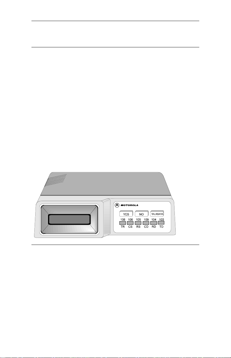
Physical
The V.3600 has a 32 character LCD front panel with three pushbuttons
for option selection (Figure1-1).
Figure 1-1. Typical Front Panel
1-4 V.3600
V.3600
Page 23
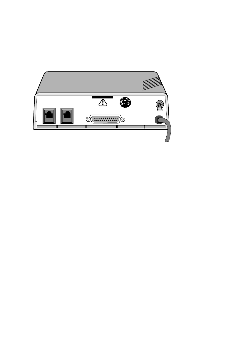
Introduction
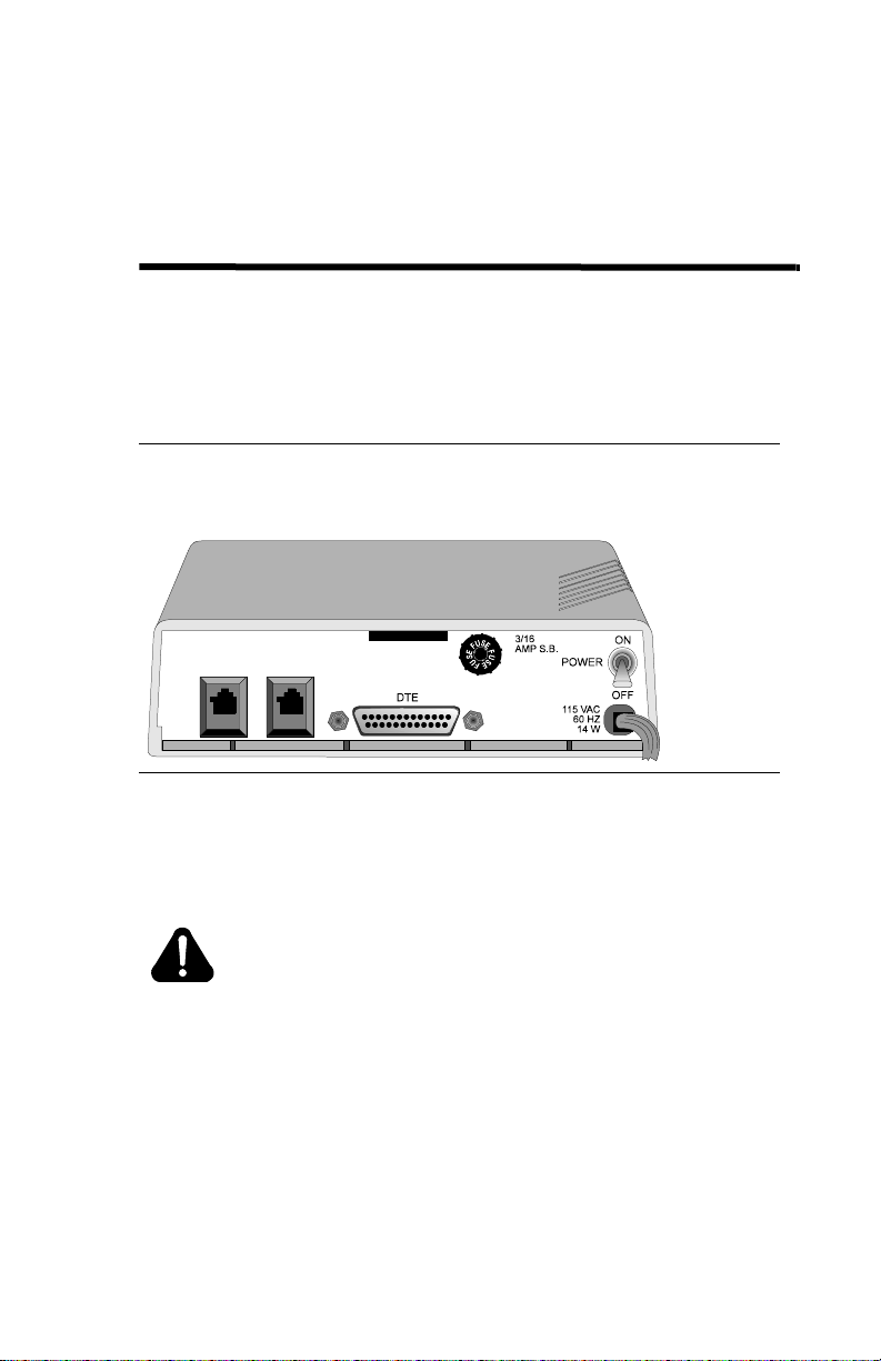
The V.3600 rear panel has an EIA-232 DTE connector, an 8-pin
TELSET/LEASED LINE jack, an 8-pin DIAL jack, the power switch,
fuse, and cord (Figure 1-2).
TELSET
LEASED LINE
DIAL
DTE
3/16
AMP S.B.
Figure 1-2. Rear Panel (115 Vac Model)
115 VAC
60 HZ
1/4 AMP
1
0
V.3600 1-5
Page 24
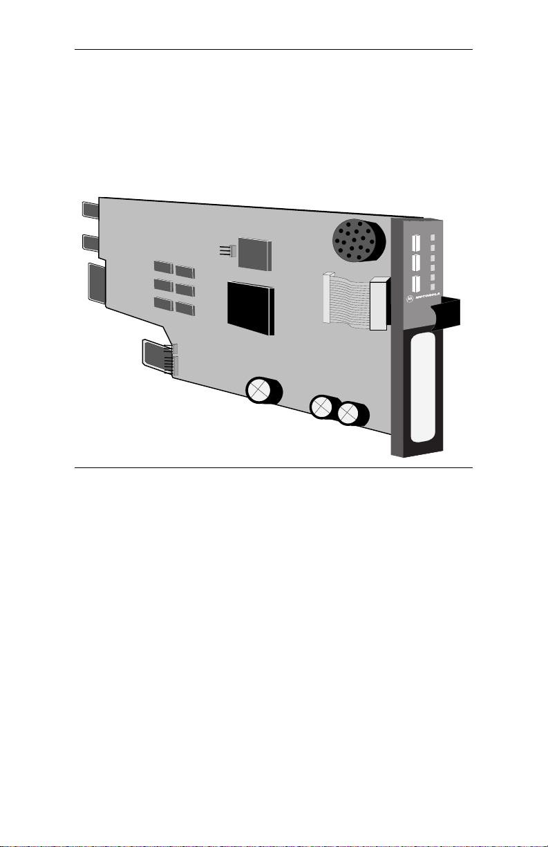
Introduction
RM16M Unit
The shelf-mount RM16M unit (Figure 1-3) has edge connectors that
insert into the shelf backplane. The shelf backplane performs the same
functions as the standalone rear panel. Refer to the “Shelf-Mount
RM16M V.3600 Installation” section on page 2-9.
V.3600
Figure 1-3. RM16M Version of the V.3600
1-6 V.3600
Page 25
Chapter 2
Installation
This chapter provides information on mechanical and electrical
installation of the modem.
Electrical Installation
The rear panel (Figure 2-1) includes DTE cable and telephone line
connectors.
TELSET
LEASED LINE DIAL
Figure 2-1. Rear Panel Connections (115 Vac Model)
AC Power Connection
Power is supplied through a 6-foot line cord with a grounded 3-wire plug.
DC Power Connection
Caution
To protect the DC-to-DC converter from damage, ensure
the positive and negative leads are properly connected.
If the modem is equipped for 12-60 VDC power input, connect the power
to the terminal block attached to the modem back panel. A chassis ground
connection is also supplied on the terminal block.
V.3600 2-1
Page 26

Installation
If the modem is equipped for +/- 12/+5 VDC power input, connect the
VDC power to the amp connector. A chassis ground connection is also
supplied on the terminal block.
DTE Connection
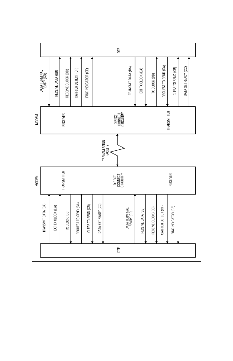
The DTE connector is a 25-pin D-series type conforming to EIA-232
specifications. Y o u must use a shielded DTE cable to comply with EMC
requirements. Pin signals are shown in Figure 2-2 and are described in
Table 2-1.
2-2 V.3600
Page 27
Installation
Figure 2-2. Digital Interface Signals
V.3600 2-3
Page 28

Installation
Table 2-1. Pin Signal Descriptions
EIA-
Pin
232D
1101
2BA103
3BB104
4CA105
5CB106
6CC107
7AB102
8CF109
9
10
* Modem options may force these signals on or cause them to be ignored.
** Refer to Appendix C, Hardware Options.
† This function can be disabled or its logic sense reversed by hardware straps.
CCITT
V.24 Signal Description
Shield No connection
Transmit-
ted Data
Received
Data
Request to
Send
Clear to
Send
Data Set
Ready
Signal
Ground
Received
Line
Signal
Detector
--
--
+12 Volts +12 voltage reference
-12 Volts -12 voltage reference
Serial digital data (to be modulated)
from a data terminal or other digital
data source: Sync h ronous data must be
accompanied by the modem transmit
clock (pin 15) or by an ex te rna l da ta
rate clock (pin 24). Data transitions
should occur on positive-going clock
transitions; asynchronous data does not
require a transmit clock.
Serial digital data output to the D TE
interface: Sync data is accompanied by
an internal data rate (receive) clock
(pin 17) that has positive-going
transitions on the data t ransition. Async
data does not require a receive clock.
A positive level to the modem when
data transmission is desired
A positive level from the modem in
response to Request to Send and when
the modem is ready to transmit. *
A positive level from th e m o dem wh en
power is on and ready to op er a te : I n
dial-up operation, the modem must be
off hook to give a high DSR signal.*
Signal or common signal and dc power
ground. **
A positive level from the modem
indicating the presenc e of a received
signal (carrier detect). *
2-4 V.3600
Page 29

Installation
Table 2-1. Pin Signal Descriptions (Continued)
EIA-
Pin
232D
11
15
17
18
20
21
22
23
24
25
* Modem options may force these signals on or cause them to be ignored.
** Refer to Appendix C, Hardware Options.
† This function can be disabled or its logic sense reversed by hardware straps.
CCITT
V.24 Signal Description
--
DB 114
DD 115
-- 141
CD 108.2
-- 140
CE 125
CH 111
DA 113
-- 142
Signal
Quality
Indicator
Transmit
Clock
(DCE)
Receive
Clock
Local
Loopback
Data
Terminal
Ready
Remote
Digital
Loopback
Ring Indicator
Data Rate
Select
External
Transmit
Clock
Test Mode Indicates the modem is in a test mode.
This circuit indicates probability of
errors in the received data: a positive
level indicates poor signal quality
while a negative level indicate s good
signal quality. †
A transmit data rate clock output for
use by an external data source: P ositive
clock transitions correspond to data
transitions.
A receive data rate clock ou tput for u se
by an external data sin k: Po sitiv e clo ck
transitions correspond to data
transitions.
A positive level causes the modem to
enter the local analog loopback test
mode.*
This circuit is positive when the DTE is
ready to originate or answer a call in
dial-up oper ation . DTR m ust a lways be
active (high) in 2-wire private line
operation. Cycling DTR causes
retraining.*
A positive level causes a digital
loopback test mode at the remote
modem.*
In direct dial operation this circuit is
positive in response to an incoming
ring signal.*
Supplies a data rate control input to
select primary or fallback data rate:
Negative voltage selects primary data
rate and positive voltage selects
fallback data rate.*
A serial data rate clock input from the
data source. Positive clock transitions
correspond to data transitions.
V.3600 2-5
Page 30

Installation
Telephone Line Connection
The modem operates in these line-related modes:
•Dial
• Leased
Dial Mode: PSTN Connection (DIAL jack)
The public switched telephone network (PSTN) is a two-wire dial
network. Modems are registered with the Federal Communication s
Commission (FCC) for direct connection to the PSTN. The label on the
chassis bottom gives the FCC registration number and other information
required for network operation.
2-6 V.3600
Page 31

Direct connection to the PSTN is shown in Figure 2-3.
Installation
8-pin
Connectors
TELSET
LEASED LINE
Cable supplied
with telephone
RJ11C jack installed
by telephone company
Notes:
1. The TELSET jack is provided on the back of the modem for use with a
standard rotary or tone dial telephone regardless of the telephone
jack arrangement ordered from the telephone company.
2. This standard rotary or tone dial telephone set can be used for
originating a call or for voice communication. For sites requiring
only auto answer capability, a phone is not needed.
3. For connector pin-outs, refer to Appendix B.
DIAL
DTE Connector
Screws
DTE
25-Pin Connector
Shielded DTE Cable
Use 8-pin Modular (at modem end) to 6-pin
Modular (at RJ11 wall jack end) connector.
EIA-232
to DTE
Figure 2-3. Dial-up Connection (115 Vac Model)
Leased Line Connection (TELSET/LEASED LINE Jack)
Private or leased lines use four -wire or two-wire lines. In this mode, th e
user configures the unit for four-wire or two-wire operation, depending
on the private line service used.
V.3600 2-7
Page 32

Installation
The telephone company will install the leased line and wall jack at your
site. The line connects to the modem at the 8-position TELSET/
LEASED LINE jack.
Figure 2-4 shows a typical modem hookup for operation over private
leased lines with dial backup.
Telset Leased
Line Jack
Dial
(May be used for
Dial Backup)
TELSET
LEASED LINE
Leased Line
Cable
Leased Line
Jack
Notes:
1. Set the transmit output level to 0dBm.
2. DTR, which is the signal on pin 20 of the DTE interface, must be active
or the option DTE IGNORED must be set for 2-wire OR 4-wire leased line operation.
3. The connection shown includes dial backup. Connect only the leased-line jack
to the modem’s Telset jack for regular Leased-line use.
4. For a 2-wire Leased-line connection, Pins 1 and 2 of the Leased-line connection
are used for Tx and Rx data. For a 4-wire Leased-line connection, Pins 1 and 2 are
used for Tx, and Pins 7 and 8 are used for Rx.
5. For connector pin-outs, refer to Appendix B.
RJ11C
DIAL
DTE
EIA-232
25-Pin Connector
to DTE
Use 8-pin Modular (at modem end) to 6-pin
Modular (at RJ11 wall jack end) connector.
(Optional connection for dial backup use.)
Figure 2-4. Leased Line Connection (115 Vac Model)
2-8 V.3600
Page 33

Installation
Shelf-Mount RM16M V.3600 Installation
Go to Appendix C, Hardware Options to check the board options before
installation.
Shelf-mount RM16M V.3600s should be installed or replaced by
personnel familiar with shelf-mount installation. Th e unit has an edge
connector that inserts into a receptacle located on the backplane and
power bus.
Note
Figure 2-5 represents a typical dialup connection using one of
the most common rack shelves. Connect cables as appropriate
for any compatible RM16M shelf.
RJ11C, RJ45S or
RJ11C jack, installed
RJ41S jack installed
by telephone
company
To DTE
Shelf backplane
(with RM16M V.3600 installed)
Figure 2-5. RM16M Connections
V.3600 2-9
Page 34

Page 35

Chapter 3
Getting Started
Option Selection
There are six ways to change or select options:
• LCD - Using the front panel LCD and pushbuttons is simple,
straightforward, and requires the least amount of technical
background. Chapter 4 explains LCD operation.
• AT Commands - The AT command set can be used to select modem
options. Chapter 5 describes AT commands.
• Status Registers - A series of special ATS commands allows the
operator to change the decimal or hexadecimal value of a memory
byte to change one or more options in that byte. Chapter 10
describes S-registers.
• Single Bit Status Registers - A second series of special ATS
commands allows the user to change single bits with in a byte to
change an option. Chapter10 also explains single bit control.
• Software Program - A wide variety of software programs is
available, or advanced computer users can write their own software
programs to interact with the modem. This manual does not discuss
software programs.
• V.25 bis Commands - An extended set of V.25 commands allows
selection of modem options during synchronous operation. Refer to
Chapter 11.
Power-Up
A power-up procedure is not required. Turn on the modem using the ON/
OFF power switch on the rear panel. The modem is fa ctory configured to
operate in most public switched telepho ne applicati ons. If yo u have stored
a desired option set it will be automatically be restor ed at power-up.
V.3600 3-1
Page 36

Getting Started
Placing a Call
There are three methods for placing a call:
Dialing with a Standard Telephone
1) Lift the telephone receiver. Wait for the dial tone.
2) Dial the number of the remote site.
3) When the answer back tone is heard, immediately press the
TALK/DATA button and hang up the telephone. Th e mo dems go
through a connection sequence and establish a data link. If a data
link is not established, return to Step 1.
4) After the link is established, hang up the telephone.
Autodialing from Front Panel
1) If the number to be dialed has not been stored, advance to Main
Menu #6, CHANGE PHONE NUMBER.
2) Enter the number by using the NO pushbutton to scroll the menu
and YES to select.
3) After the number is entered, press YES to store the number.
4) Advance the LCD to Main Menu #2, DIAL STORED
NUMBER.
5) Select the number to dial and press YES. The number is dialed,
and the modems follow the same process as two telephone s.
Autodialing from a Terminal with the AT Commands
To dial a number, for example 555-1212, type AT D 555-1212 and
press Enter, or enter ATDSn where n equals one of the stored telephone
number locations 1-9.
The modem dials the number--either pulse or tone, whichever is
currently in effect--and takes the role of the originate modem.
Refer to the “Dial Commands” section on page 5-13 for additional
dialing comma nds.
3-2 V.360 0
Page 37

Getting Started
Answering a Call
There are three ways to answer a call:
Autoanswering
Normally the modem is configured to autoanswer on the first ring. If a
telephone is plugged into the TELSET/LEASED LINE jack, it will also
ring.
Answering Manually
When detecting a ring, the modem LCD displays ringing status.
Press TALK/DATA to answer the call and place the modem in the data
mode.
Answering from Terminal with AT Command Set
The modem displays the ring resp onse.
T o answer a call, type ATA. The mo dem send s an answer-back tone and
attempts to connect to the remote modem.
Ending a Call
There are two ways to complete a call:
Ending a Call Using the Front Panel
1) Press the TALK/DATA pushbutton. DO YOU WANT T O
DISCONNECT will be displayed.
2) Answer YES.
Ending a Call from a Terminal with the AT Command Set
1) Enter +++ and the modem will enter command mode.
2) Enter ATH and the modem will terminate the call.
V.3600 3-3
Page 38

Getting Started
Reasons for Call Termination
The conditions described in Table 3 -1 cause call termination.
Table 3-1. Reasons for Call Termination
Condition
Abort Disconnect
(No answer, busy signal,
no modem, etc.)
ATH Disconnect command.
Loss of Carrier
Disconnect
Receive Long Space
Disconnect
DTR Disconnect Disabled or select 10 ms to 2.55 sec
Loss of Line Current
Cleardown A disconnect method used in V.32 and V.34 mode.
LCD Display When TALK/DATA is pressed, the LCD displays
Train Timeout Modem fails to establish communication with
Protocol Link
Establishment Failure
Inactivity Timeout Default is 0 or disabled; select for disabled or 1 to
Protocol Retry Limit
Exceeded
Minimum DCE Speed A connection occurred at a rate less tha n mi ni mum .
Description
Default 30 sec; select 1 to 255 sec
(S-register 7).
Select 100 ms to 25.5 sec (S -r e gis te r 10 ) .
Disabled or select 2 sec.
(S-register 25).
DO YOU W ANT TO GO TO TALK? When YES is
pressed modem hangs up, if no telephone is
connected or if the connected telephone is not off
hook. Pressing NO displays DO YOU WANT TO
DISCONNECT? Press YES to disconnect.
remote site. Default is 30 seconds (S-register 7).
Reliable mode only; failure to establish reliable
link.
255 minutes (S - register 8).
12 retransmissions of the frame.
Security Password
Failure
Security Callback Security callback is enabled and a new remote
Maximum password entry attempts exceeded.
connection is established. The modem disconnects
and places a call to the pr ogrammed number.
3-4 V.360 0
Page 39

Getting Started
Table 3-1. Reasons for Call Termination (Continued)
Condition
Signal Quality Leased line operation with dial backup enabled;
Test Mode entered Certain test modes require call termination.
Modem power is turned
off.
Description
extended loss of carrier or 4 unsuccessful retrains
in 3 minutes causes dial backup.
V.3600 3-5
Page 40

Page 41

Chapter 4
Front Panel Operation
The liquid-crystal display (LCD) front panel provides easy real-time
access to modem configuration and status. You can use the LCD at any
time to modify modem options or to get information about modem
operation and status. All of the major modem options can be controlled
through the LCD interface without an external terminal or phone line
connection. Operation of the LCD can be secured using a password
protection feature. A remote modem can even be configured using the
local LCD, through the use of the front panel remote configuration feature.
LED Descriptions
The V.3600 LED indicator functions are as follows:
• TR (Terminal Ready). TR lights when the DTE asserts Data
Terminal Ready. This signal is input on pin 20 (CCITT V.24/108.2).
• CS (Clear to Send). CS lights when th e modem is ready to send data
to the DTE. This signal is output on pin 5 (CCITT V.24/106).
• RS (Request to Send) . R S li ghts wh en the DTE is ready to send d at a
to the modem. This signal is input on pin 4 (CCITT V.24/105).
• CD (Carrier Detect). CD lights when the received audio carrier
signal is detected or, if enabled, when error control protocol
negotiation is complete. This signa l is output on pin 8
(CCITT V.24/109).
• RD (Received Data). RD lights for a data space condition at the
receive data output, indicating receive data output activity. This
signal is output on pin 3 (CCITT V.24/104).
• TD (Transmit Data) TD lights for a data space condition at the
transmit data input, indicating transmit data input activity. This
signal is input on pin 2 (CCITT V.24/103).
V.3600 4-1
Page 42

Front Panel Op e ration
LCD Menus
The V.3600 has seven main LCD m enus that support m odem operat ions.
Table 4-1 lists them, in the following sequence:
• MODEM STATUS
• DIAL STORED NUMBER
• DISPLAY STATUS
• SELECT TEST
• MODIFY CONFIGURATION
• CHANGE PHONE NUMBERS
• FRONT PANEL FEATURES
LCD Menu Operation
The LCD menu is shown in Table 4-1, as follows:
• The first column lists the seven main menu categories.
• The second column is the submenus, listing functions for each
category in the main menu.
• The third column lists specific items for submenu functions.
• The fourth column lists option choices or status for the specific
items in the third column.
• The fifth and sixth columns in the table show associated AT
commands and S-registers as a cross reference.
Each column item has a correspondin g header in the previous co lumn. If
an option setting is selected or if all settings have been scrolled through,
the display returns to the header.
Because of the menu structure and option choices, not all main menus
use all four columns in Table 4-1. However, option selection and
sequence are the same.
While operating in the option menu, pressing NO scrolls vertically
down the columns; pressing YES advances horizontally across the
columns. However, responding to the LCD prompt is the best way to
reach an option. If NO is pressed and held, the LCD scrolls through the
menus. Press the TALK/DATA button to return to the previous menu.
4-2 V.360 0
Page 43

Front Panel Operation
Table 4-1. LCD Menu Option Selection
Main Menu LCD Messages
1 MODEM-
STATUS
Main Menu Submenu Submenu Item
2DIAL
STOREDNUMBER?
3DISPLAY
STATUS?
(status only)
4 SELECT
TEST?
When modem is not online, the display flashes and shows the status from the
*
last connection .
† Modem must be online with protocols disabled.
V.34 33600 IDLE
Shows the current modulation, bit
rate, and modem status.
DIAL #1-9 YES, NO DSn
DTE
SIGNALS
PROTOCOL* NONE
COMPRESSOR*
CARRIER
DESCRIPTIONS*
LAST DISCONNECT
REASON
(Offline test
only)
(Online test) LOCAL DIGITAL
QM ON/OFF
DSR ON/OFF
OH ON/OFF
RI ON/OFF
MNP 2, 3, 4, 5
LAPM
NONE
MNP 5, V.42b
RECEIVE LEVEL
NEAR END
ECHO
LEVEL
FAR END ECHO
LEVEL
FAR END ECHO
DELAY
FREQUENCY
TRANSLATION
BAUD RATE
RX BIT RATE
TX BIT RA TE
DISPLAY
STATUS
LOCAL ANALOG
LOOP
LOCAL ANALOG
LOOP WITH TP
LOOP †
(Press NO to advance
to MAIN 2)
Item
Option
DISPLAY
STATUS
DISPLAY
STATUS
DISPLAY
STATUS
DISPLAY
STATUS
INITIATE,
EXIT
INITIATE,
EXIT
INITIATE,
EXIT
AT
Com.S-Reg
(n=1-9)
--- ---
--- ---
--- ---
--- ---
I5
&T1 S16
&T8 S16
&T3 S16
SReg
S91
S67
---
V.3600 4-3
Page 44

Front Panel Op e ration
Table 4-1. LCD Menu Option Selection (Continued)
Main Menu Submenu Submenu Item
SELECT
4,
TEST?
(continued)
c
o
n
t.
5MODIFY
CONFIGURATION?
Lease line only.
*
** 9600U is only valid for V.32 bis modulation.
(Online test
continued)
CHANGE
MODEM
OPTIONS?
REMOTE
DIGITAL LOOP †
REMOTE DIGI
TAL LOOP WITH
TP †
TEST PATTERN† INITIATE,
CHANGE
LEASED/ DIAL
LINE?
CHANGE
MODULATION?
CHANGE MAX
DCE RATE?
† Modem must be online with protocols disabled.
Item
Option
INITIATE,
EXIT
INITIATE,
EXIT
EXIT
2 WIRE/
4 WIRE
AUTO-
MODE
V.21
BELL 103
B212A
V.22 bis
V.27 ter *
V.29 *
V.33 *
V.32bis
V.34
33600
31200
28800
26400
24000
21600
19200
16800
600
14400
12000
7200
9600
9600U **
4800
2400
1200
300
DTE SPEED
AT
Com.S-Reg
&T6 S16
&T7 S16
%T ---
&L1,&LS27
*MM
*MM1
*MM2
*MM4
*MM5
*MM6
*MM8
*MM10
*MM11
*MM12
%B18
%B17
%B16
%B15
%B14
%B13
%B12
%B11
%B10
%B9
%B8
%B7
%B6
%B5
%B4
%B3
%B2
%B1
%B
S88
S69
4-4 V.360 0
Page 45

Front Panel Operation
Table 4-1. LCD Menu Option Selection (Continued)
Main Menu Submenu
MODIFY
5
CONFIGURATION?
c
(continued)
o
n
t.
Lease line only.
*
** 9600U is only valid for V.32 bis modulation.
CHANGE
MODEM
OPTIONS?
(continued)
Item
CHANGE MIN
DCE RATE?
CHANGE V.34
RATE THRESHOLD?
V.34 ASYM
RATES
NORMAL
ORIGINATE
FORCED
ANSWER*
V.22 GUARD
TONE
V.32 FAST TRAINENABLE
AUTO RETRAIN ENABLE
SQ AUTO RATE HIGH BER
TRANSMIT
CLOCK
SELECT
Submenu
Item
Option
33600
31200
28800
26400
24000
21600
19200
16800
600
14400
12000
7200
9600
9600U **
4800
2400
1200
300
DTE SPEED
LOW BER
MED BER
HIGH BER
ENABLE
DISABLE
NORMAL
ORIG.
FORCED
ANS.
DISABLE
550 Hz
1800 Hz
DISABLE
DISABLE
MED BER
LOW BER
DISABLED
INTERNAL
EXTERNAL
RECEIVE
AT
Com.S-Reg
%L18
%L17
%L16
%L15
%L14
%L13
%L12
%L11
%L10
%L9
%L8
%L7
%L6
%L5
%L4
%L3
%L2
%L1
%L
*TH
*TH1
*TH2
*AS1
*AS
*OR
*OR1
&G
&G1
&G2
*FT1
*FT
%E1%ES60
%R3
%R2
%R1
%R
&X
&X1
&X2
S69
---
S96
S14
S23
S29
S53
S27
V.3600 4-5
Page 46

Front Panel Op e ration
Table 4-1. LCD Menu Option Selection (Continued)
Main Menu Submenu Submenu Item
MODIFY
5
CONFIGURATION?
c
(continued)
o
n
t.
Lease line only.
*
† Dial line only.
CHANGE
MODEM
OPTIONS?
(continued)
CHANGE
PROTOCOL
OPTIONS?
DIAL TRANSMIT
LEVEL
RING
FREQUENCY
LIMIT
LEASE TRANSMIT LEVEL*
LINE CURRENT
DISCONNECT†
LONG SPACE
DISCONNECT†
DIAL BACKUP* MANUAL
LOOKBACK
TIME*
LAPM
PROTOCOL
MNP
PROTOCOL
PROTOCOL
FALLBACK
DATA COMPRESSION
Item
Option
-9 dBm to
-21 dBm
ENABLE
DISABLE
0 to -21 dBm *TLn S52
OFF
SHORT
LONG
ENABLE
DISABLEY1Y
AUTOMATIC
0 DISABLED
to 255
MINUTES
ENABLE
DISABLE
ENABLE
DISABLE
ENABLE
DISABLE
DISABLE
NORM
TX
RX
AT
Com.
*TDn S51
*RL1
*RL
*LC,
*LC1,
*LC2
*DB
*DB1
--- S28
\N4, \N5,
\N6, \N7
\N, \N1,
\N2, \N3
\N2, \N3,
\N6, \N7
\N, \N1,
\N4, \N5
\N3, \N5,
\N6, \N7
\N, \N1,
\N2, \N4
%C
%C1
%C2
%C3
SReg
--
S32
S21
S32
S70
S70
S70
S56
4-6 V.360 0
Page 47

Front Panel Operation
Table 4-1. LCD Menu Option Selection (Continued)
Main Menu Submenu Submenu Item
MODIFY
5
CONFIGURATION?
c
(continued)
o
n
t.
CHANGE
PROTOCOL
OPTIONS?
(continued)
CHANGE DTE
OPTIONS?
DTE SPEED DTE=DCE
DTE FLOW
CONTROL
DCE FLOW
CONTROL
XON/XOFF PASS
THROUGH
INACTIVITY
TIMER
BREAK
OPTION
V.42 FAST
DETECT
DATA
OPERATION
DTE RATE
(Async)
CHAR SIZE
(Async)
PARITY (Async) NO, EVEN,
Item
Option
CONSTANT
DTE
DISABLE
XON/XOFF
CTS
RTS/CTS
DISABLE
XON/XOFF
CTS
ENABLE
DISABLE
OFF, 15, 30,
45, 60, 75,
90 MIN
0, 1, 2, 3, 4, 5\K, \K1,
ENABLE
DISABLE
SYNC
ASYNC
300,
600,1200,
2400, 4800,
7200, 9600,
12000,
14400,
16800,
19200,
21600,
24000,
26400,
28800,
31200
33600
38400
57600,
115200
7 BIT
8 BIT
ODD
AT
Com.S-Reg
\J1
\J
\Q
\Q1
\Q2
\Q3
\Q4
\Q5
\Q6, \Q7
\X1
\X
\TLn S58
\K2, \K3,
\K4, \K5
\M1
\M
&M1, 2,
3, 4, 5, 6
&M
--- S80
--- S61
--- S61
S70
S54
S54
S54
S59
S70
S27
S30
V.3600 4-7
Page 48

Front Panel Op e ration
Table 4-1. LCD Menu Option Selection (Continued)
Main Menu Submenu Submenu Item
MODIFY
5
CONFIGURATION?
c
(continued)
o
n
t.
CHANGE DTE
OPTIONS?
(continued)
DIAL METHOD ASYNC
AT COMMAND
SET
CHARACTER
TYPE (V.25
SDLC DATA
FORMAT
DTR STATE IGNORE
DSR STATE NORMAL
DCD STATE NORMAL
CTS STATE NORMAL
Item
Option
DTR,
MANUAL,
V.25
BISYNC,
V.25 SDLC
V.25 bis
ASYNC
ENABLE
DISABLE
ASCII,
only)
EBCDIC
NRZ, NRZI --- S30
RECALL
CMD
DISCONNECT
RESET
FORCED
HIGH
OFF 5 SEC
ON
DISCONNECT
FOLLOWS
OH
FORCED
HIGH
OFF 5 SEC
ON
DISCONNECT
FOLLOWS
REMOTE
RTS
FORCED
HIGH
CTS
FOLLOWS
DCD
CTS=RTS
AT
Com.S-Reg
&M1,
&M2
&M3
&M4
&M5
&M6
*NT1
*NT
--- S30
&D
&D1
&D2
&D3
&S1
&S
&S2
&S3
&C1
&C
&C2
&C3
&R
&R1
&R2
&R9
S27
S30
S29
S21
S21
S21
S21
S72
4-8 V.360 0
Page 49

Front Panel Operation
Table 4-1. LCD Menu Option Selection (Continued)
Main Menu Submenu Submenu Item
MODIFY
5
CONFIGURATION?
c
(continued)
o
n
t.
CHANGE DTE
OPTIONS?
(continued)
CHANGE
TEST
OPTIONS?
CHANGE
DIAL
OPTIONS?
RTS/CTS DELAY 0 to 150 ms
DTE COMMANDED
FALLBACK
OPTIONS RES/
RETND AT DISC
BILATERAL
DIGIT AL LOOP
DTE LOCAL
TEST
DTE REMOTE
TEST
REMOTE COMMANDED
TEST TIMEOUT OFF, 60,
DIAL TYPE PULSE,
AUTODIAL # OFF, 1 - 9 *AUn
DIAL TONE BLIND DIAL
WAIT DELAY
(Blind Dial)
PAUSE DELAY 1, 2, 3, 4, 8,
CALL TIMEOUT 15, 30, 45,
ANSWER RING #X1, 2, 4, 8, 16 --- S0
Item
Option
(10 ms)
ENABLE
DISABLE
RESTORED
RETAINED
ENABLE
DISABLE
ENABLE
DISABLE
ENABLE
DISABLE
ENABLE
DISABLE
120, 180.
240 SEC
TONE
WAIT FOR
DIAL
TONE
1, 2, 3, 4, 8,
16, 32 SEC
16, 32 SEC
60, 75, 90,
105, 120
SEC
AT
Com.S-Reg
--- S26
*FB1
*FB
*RO1
*RO
*DG1
*DG
*LA1
*LA
*RD1,
*RD
&T4
&T5
--- S18
P, T S14
(n=1-9)
X, X1,
X3 X2,
X4
--- S6
--- S8
--- S7
S53
S29
S34
S34
S34
S23
---
S22
CHANGE
SPEAKER
OPERATION?
AUTOCALLBACK ENABLE,
VOLUME
CONTROL
DISABLE
LOW
HIGH
--- S72
L1, L2L3S22
V.3600 4-9
Page 50

Front Panel Op e ration
Table 4-1. LCD Menu Option Selection (Continued)
Main Menu Submenu Submenu Item
MODIFY
5
CONFIGURATION?
c
(continued)
o
n
t.
6 CHANGE
PHONE
NUMBERS?
7 FRONT
PANEL
FEATURES?
Password of 0000 disables front panel security.
*
CHANGE
SPEAKER
OPERATION?
(continued)
LOAD/STORE
OPTION SET?
SPEAKER
CONTROL
LOAD
FACTORY
OPTION
LOAD USER
OPTION SET12
STORE
PRESENT
OPTIONS
USER OPTION
AT RESET
PHONE
NUMBER
CHANGE RMT
PASSWORD?
ENTER REMOTE
CONFIGURATION
EXIT REMOTE
CONFIGURATION
CHANGE FRONT
PANEL PASSWORD
Item
Option
ON UNTIL
CARR
DETECT
ALWAYS
ON
OFF WHILE
DIALING
ALW AYS
OFF
NO, 1-9 &Fn
1
2
1
2
ENTER
NUMBER
32 digits
ENTER
PASSWORD
ENTER
REM CFG
PASSWORD
EXIT &T ---
ENTER
PASSWORD *
ACTIVATE
SECURITY
AT
Com.S-Reg
M1
M2
M3
M4
(n=1-9)
Z0
Z1
&W
&W1
&Y
&Y1
&Zx=n
(n=
# and
modifiers)
*CNx,n
%P ---
%T ---
--- ---
--- ---
S22
---
---
---
---
---
phone
4-10 V.3600
Page 51

Front Panel Operation
Front Panel Security
The Front Panel Security feature provides password protection for fro nt
panel menu access. The modem is shipped from the factory with this
feature disabled.
The Front Panel Security password is a 4-digit string that can be set to
any combination of digits f rom “000 0” t o “999 9”. S el ecti ng a pas swor d
of “0000” disables Front Panel Security; any other password enables it.
IMPORTANT: Without your password, you cannot access front panel
configuration. Keep your password in a safe place. If you forget your
Front Panel Security password, contact Technical Support. Refer to
“Calling Technical Support” section on page 12-2.
When this feature is enabled, it can be activated in these ways:
• Explicitly, by a front panel screen under Main Menu #7
• By the modem, when no front panel but tons have been p ressed for
3 minutes
When Front Panel Security is activated, th e front panel menu returns to
Main Menu #1 and the front panel is secured.
In secured state, the Main Menu #1 screen continues to maintain modem
status, but a password must be entered before other front panel screens
may be accessed. Pressing any front panel button causes the modem to
prompt for the fr ont panel passw ord. After the pa ssword has been
entered, a message briefly displays the result of the password validation
process and, depending on the result, Front Panel Securi ty either
becomes inactive or returns to its active state.
During password entry, the front panel buttons are operate as follows:
• Pressing NO makes the character at the cursor change to the next
valid password character.
• Pressing YES while the cursor is on any of the first three password
characters makes the cursor advance to the next password
character. When the cursor is on the last password character,
pressing YES makes the modem accept the displayed password.
• P res sin g TALK/DATA while the cursor is on the first password
character aborts password entry. When the cursor is on any other
character, this button makes the cursor move to the first character.
V.3600 4-11
Page 52

Page 53

Chapter 5
AT Commands
This chapter describes commands used to select options and operate the
modem. Some options depend on, or are restricted by, the mode of
operation. Appendix E provides a quick reference list.
Command Categories
The modem offers these major categories of command statements:
• Response (page 5-5)
• Dial (page 5-13)
• Answer (page 5-17)
• T ermin al Interface (page 5-19)
• General (page 5-22)
• Private Line (page 5-33)
• Configuration (page 5-37)
• Remote Configuration (page 5-41)
Other AT command groups are discussed in these chapters:
• Protocol (Chapter 6)
• T est (Chapter 7)
• Security (Chapter 8)
• Fax (Chapter 9)
• S-registers (Chapter 10)
Operation Modes
In asynchronous operation, the modem functions in one of these modes:
• Offline Command Mode
• Online Command Mode
• Data Mode
V.3600 5-1
Page 54

AT Commands
Offline Command Mode
In offline command mode (generally referred to as comman d mode), the
modem communicates with the computer or terminal. Commands can
be entered separately or in strings. There is no data communication link
established in this mode.
Online Command Mode
This mode is entered from the data mode after the escape command has
been entered. The escape command is perfo rmed by en tering the escape
character (+ is the default) three times. The data communication link
remains established but data transmissio n is suspended. The modem
then accepts commands as it does in offline command mode.
Data Mode
The modem goes to data mode (online) after it acknowledges the p roper
signal and successfully connects with a compatible modem. In data
mode, the modem sends and receives data, but does not accept or
execute command instructions.
Example: The modem is in the command state. The D command and
phone number are used to dial a remote mo dem. The local modem waits
to receive an answer back tone from the remote modem. When the local
modem receives the carrier , it leaves th e command state and go es online
in the data mode. At this time, both modems are using the telephone line
and a communication link is established.
Sending Commands to the Modem
When the computer, modem, and monitor are on, an instruction can be
sent to the modem telling it what function or activity to p erfor m. The
instruction, called a command statement, command string, or command,
is typed using the computer/terminal keyboard. The command statement
temporarily resides in a section of memory called the command buffer.
Each command statement is made up of characters, numbers, and
keyboard symbols such as the & and % signs. Commands must be
written in a specific form so the modem recognizes and follows the
instruction.
5-2 V.3600
Page 55

AT Commands
Creating a Command Statement — AT
To create a command statement use the following steps:
1) Type AT. This is the Attention Code telling the unit a command
statement follows.
2) Type the command.
3) Press the Enter key to send the command statement to the
modem.
An example of a command statement using the dial command (D)
follows.
ATD554-1212
This statement can be read as “Attention: Dial 554-1212.”
Another AT command statement example is:
ATZ
This statement can be read as “Attention: execute the Z command.”
After entering a command line the modem returns a response message
indicating whether or not the command was accepted or giving the data
requested by the command line.
To clear command statements from the buffer you can:
• Turn the modem off,
•Enter AT, or
• Use the DTR reset feature (“Data T erminal Ready — &D” section
on page 5-20).
Autobaud
The attention code (AT) is analyzed by the modem to determine the
transmission speed, parity, and bits per character us ed b y the DTE. This
autobaud process is repeated each time the AT command prefix is sent.
Guidelines for Creating Command Statements
The attention code (AT) may be upper or lower case but not a
combination like aT.
•Press the Enter key to execute a command.
• The command buffer can hold 80 characters.
• Use the backspace or delete key to erase the last character.
Even though the initial AT code must be all upper or lower case,
characters that follow can be any mix of upper and lower case.
V.3600 5-3
Page 56

AT Commands
Monitor Display
As commands are typed they appear on the monitor so the operator can
verify the input. This is called local character echo. The echo may be
turned on or off using AT commands. Refer to the “Local Character
Echo — E” section on page 5-22 for details.
Command Statement Buffer
The modem temporarily stores up to 80 characters in the command
buffer. If this limit is exceeded, the modem does not accept the
command and sends an ERROR message. To correct this condition,
retype the command using 80 characters or less.
The AT characters and punctuation used in telephone numbers do not
take up space in the buffer. Blank characters used as spaces to help
increase readability are not counted. For example, the modem reads the
commands:
ATD (212) 554-1212
ATD2125551212
ATD 212 555 1212
as having 11 characters each. Commands can be typed in any of these
forms.
Backspace Key
Use the backspace key to change the command statement or correct
errors. The backspace key allows the cursor to be moved back to the
character(s) in error. The command can then be retyped from that point.
Example: ATD5551211 has been typed. To change the last 1 to 2,
press the backspace key once, type 2, and press Enter to execute the
command.
Repeating a Command — A/
This command tells the computer to repeat the last command stored in
its buffer. It automatically reexecutes the command without retyping.
The return key does not need to be pressed.
Example: The ATD5551212 command has been executed, and the
phone is busy. To repeat the instruction type A/. Do not use AT before
this command: AT empties the buffer.
5-4 V.3600
Page 57

AT Commands
Numbered Commands
Commands that start with the same letter are distinguished by a number
following the letter.
For example, the M0 command selects speaker always off, M1 speaker
on until carrier detected, and M2 selects speaker always on.
Note
The zero (0) may be omitted; the commands M and M0 are
identical. This manual uses the nonzero form. The modem
treats both the same, but zeros count against the buffer total.
Group Commands
A group of commands can be typed in a single command statement.
Pressing the Enter key sends the entire command string to the modem,
which executes each command individually in the order it appears in the
command statement reading from left to right.
For example, the command statement ATQ0V0L3DT5551212 means
• AT Attention.
• Q Allow response messages to be sent.
• V Select digit code responses.
• L3 Select high volum e.
• DT Tone dial 555-1212.
The modem executes the AT command fo llowed b y the Q, V, L, D, and T
commands. ATQ0V0L3DT5551212 can be read as
ATQVL3DT5551212. Eliminating zeros reduces the number of
characters, allowing more room in the buffer.
The dial D command initiates the dial process so no oth e r commands,
only dial modifiers, can follow it.
Note
Bold text indicates command parameter defaults.
Response Commands
The modem communicates with the operator through response
messages. These appear on the monitor or a computer printout to show
the result of the command or action executed. Response messages can
appear as words or numbers.
V.3600 5-5
Page 58

AT Commands
Digit / Word Selection — V
The V command tells the modem which type of response message to
show on the monitor. Some software requires digit response mess ages
but words are easier to remember.
Command Operation
V Enables digit response me ssages
V1 Enables word response messages
Response Displays — Q
The Q command enables or disables response messages. The modem
still responds to commands when the response display is inhibited.
Command Operation
Q Response display on
Q1 Response display off
Q2 Response display on in originate mode only
Negotiation Displays — W
The W command enables or disables negotiation response messages.
These messages are verbose negotiation status displays to alert the user
to the link rate, protocol, and DTE rate.
Command Operation
W Disables negotiation displays
W1 Enables negotiation displays
W2 Displays DCE link rate only
Connect Message Codes — \V
The V.3600 AT\V command provides the following connect
message options
Command Operation
AT\V CONNECT DTE rate
AT\V1 CONNECT DTE rate/protocol
AT\V2 CONNECT DCE rate
AT\V3 CONNECT DCE rate/protocol
AT\V4 CONNECT DCE rx rate/DCE tx rate/modulation
5-6 V.3600
.
mode/protocol
Page 59

AT Commands
Call Progress / Connect Speed Messages X
The X command selects response code/message displays and dialing
options such as call progress monitoring, busy signal or dial tone
detection and blind dialing.
Command Operation
X Dial tone and busy signal detection not selected;
CONNECT (code 1) response messages dis played
for all speeds
X1 Dial tone and busy signal detection not selected;
appropriate CONNECT response messages or codes
displayed for da ta rate
X2 Dial tone detection only; NO DIAL TONE message
or code appears if dial tone not detected within 5
seconds
X3 Busy signal detection only; BUSY message or code
appears if dialed number is busy
X4 Dial tone and busy signal detection; appropriate
CONNECT message or code displayed
The X command followed by a dial command makes the modem go off
hook, wait the amount of t im e set in register S6, and dial the number. If
connection is made, the modem returns a CONNECT (code 1) message
to the screen regardless of the connection rate. With a basic response,
the modem does not detect a busy or no dial tone condition.
The X1 command followed by a dial command makes the modem go off
hook, wait the amount of t im e set in register S6, and dial the number. If
connection is made the modem returns an appropriate CONNECT
message or code to the screen. The modem does not detect a busy or no
dial tone situation.
The X2 command followed by a dial comman d makes the modem go off
hook and wait for a d ial to ne befor e dial ing. If a di al to ne is no t det ected
within 5 seconds, the modem sends a NO DIALTONE message and
hangs up. The modem does not detect a busy situation in this mode.
V.3600 5-7
Page 60

AT Commands
The X3 command followed by a dial command makes the modem go off
hook, wait the amount of time set in register S6 and dial the number. If
a busy signal is detected, the modem sends a BUSY message and hangs
up. If the call is completed, the appropriate CONNECT message similar
to X1 is displayed. The modem does not detect a no dial tone situation.
The X4 command followed by a dial command makes the modem go off
hook and wait for a d ial to ne befor e dial ing. If a di al to ne is no t det ected
within 5 seconds, the modem returns a NO DIALTONE message and
hangs up. If a busy signal is detected, the modem returns a BUSY
message and hangs up. If the call is completed, the appropriate
CONNECT message similar to X1 is displayed.
The X4 command combines the features of X1, X2, and X3. T he factory
setting is X4.
Note
When an X2, X3, or X4 command is in effect, an appropriate
CONNECT data rate message or code is displayed as for X1.
When a blind dial command (X, X1, X3) is in effect, the
modem waits 2 seconds or the time set in S6 and then dials.
Number Code Application — *RC
Some communications software packages use different number codes to
indicate the data rate of the serial port. This option selects either of two
commonly used number code sets.
Command Code Set Number Operation
*RC Standard 15
18
*RC1 Alternate 11
12
Note
Asterisks in AT commands are part of the command and do
not indicate footnotes.
5-8 V.3600
4800 bps
9600 bps
4800 bps
9600 bps
Page 61

AT Commands
Response Number Codes / Messages
Response number codes, messages, and their meanings are as follows.
The connect rates are serial port rates (DTE), not DCE rates.
Code
0 OK Command received
1 CONNECT Connect at 300 bps while X1, X2,
2 RING Ring detected
3 NO CARRIER Valid carrier not detected within
4 ERROR Command not recognized or too
5 CONNECT 1200 Connection made at 1200 bps
6 NO DIAL TONE No dial tone detected for 5
7 BUSY Dialed number busy (X3 or X4
10 CONNECT 2400 DTE rate 2400 bps
11, 15 CONNECT 4800 DTE rate 4800 bps
12, 18 CONNECT 9600 DTE rate 9600 bps
20 CONNECT 300 DTE rate 300 bps
22 CONNECT 7200 DTE rate 7200 bps
23 CONNECT 12000 DTE rate 12000 bps
24 CONNECT 14400 DTE rate 14400 bps
25 CONNECT 16800 DTE rate 16800 bps
26 CONNECT 19200 DTE rate 19200 bps
27 CONNECT 21600 DTE rate 21600 bps
28 CONNECT 24000 DTE rate 24000 bps
29 CONNECT 26400 DTE rate 26400 bps
30 CONNECT 28800 DTE rate 28800 bps
Message Meaning
X3, or X4 command in effect; all
rates while X command in effect
period specified by register S7, or
carrier lost for value of S10 or
more
long
seconds (X2 or X4 command in
effect)
command in effect)
V.3600 5-9
Page 62

AT Commands
Code
Message Meaning
31 CONNECT 31200 DTE rate 31200 bps
32 CONNECT 32000 DTE rate 32000 bps
33 CONNECT 33600 DTE rate 33600 bps
34 CONNECT 38400 DTE rate 38400 bps
35 CONNECT 57600 DTE rate 57600 bps
36 CONNECT 115200 DTE rate 115200 bps
37 CONNECT 230400 DTE rate 230400 bps
38 CONNECT 300/V42bis V.42 bis 300 bps connection
39 CONNECT 600/V42bis V.42 bis 600 bps connection
40 CONNECT 1200/V42bis V.42 bis 1200 bps connection
41 CONNECT 2400/V42bis V.42 bis 2400 bps connection
42 CONNECT 4800/V42bis V.42 bis 4800 bps connection
43 CONNECT 7200/V42bis V.42 bis 7200 bps connection
44 CONNECT 9600/V42bis V.42 bis 9600 bps connection
45 CONNECT 12000/
V.42 bis 12000 bps connection
V42bis
46 CONNECT 14400/
V.42 bis 14400 bps connection
V42bis
47 CONNECT 16800/
V.42 bis 16800 bps connection
V42bis
48 CONNECT 19200/
V.42 bis 19200 bps connection
V42bis
49 CONNECT 21600/
V.42 bis 21600 bps connection
V42bis
50 CONNECT 24000/
V.42 bis 24000 bps connection
V42bis
51 CONNECT 26400/
V.42 bis 26400 bps connection
V42bis
52 CONNECT 28800/
V.42 bis 28800 bps connection
V42bis
53 CONNECT 31200/
V.42 bis 31200 bps connection
V42bis
5-10 V.3600
Page 63

AT Commands
Code
54 CONNECT 32000/
Message Meaning
V.42 bis 32000 bps connection
V42bis
55 CONNECT 33600/
V.42 bis 33600 bps connection
V42bis
56 CONNECT 38400/
V.42 bis 38400 bps connection
V42bis
57 CONNECT 57600/
V.42 bis 57600 bps connection
V42bis
58 CONNECT 115200/
V.42 bis 115200 bps connection
V42bis
59 CONNECT 230400/
V.42 bis 230400 bps connection
V42bis
60 CONNECT 300/V42 V.42 300 bps connection
61 CONNECT 600/V42 V.42 600 bps connection
62 CONNECT 1200/V42 V.42 1200 bps connection
63 CONNECT 2400/V42 V.42 2400 bps connection
64 CONNECT 4800/V42 V.42 4800 bps connection
65 CONNECT 7200/V42 V.42 7200 bps connection
66 CONNECT 9600/V42 V.42 9600 bps connection
67 CONNECT 12000/V42 V.42 12000 bps connection
68 CONNECT 14400/V42 V.42 14400 bps connection
69 CONNECT 16800/V42 V.42 16800 bps connection
70 CONNECT 19200/V42 V.42 19200 bps connection
71 CONNECT 21600/V42 V.42 21600 bps connection
72 CONNECT 24000/V42 V.42 24000 bps connection
73 CONNECT 26400/V42 V.42 26400 bps connection
74 CONNECT 28800/V42 V.42 28800 bps connection
75 CONNECT 31200/V42 V.42 31200 bps connection
76 CONNECT 32000/V42 V.42 32000 bps connection
77 CONNECT 33600/V42 V.42 33600 bps connection
78 CONNECT 38400/V42 V.42 38400 bps connection
79 CONNECT 57600/V42 V.42 57600 bps connection
V.3600 5-11
Page 64

AT Commands
Code
Message Meaning
80 CONNECT 115200/V42 V.42 115200 bps connection
81 CONNECT 230400/V42 V.42 230400 bps connection
82 CONNECT 300/MNP5 MNP5 300 bps connection
83 CONNECT 600/MNP5 MNP5 600 bps connection
84 CONNECT 1200/MNP5 MNP5 1200 bps connection
85 CONNECT 2400/MNP5 MNP5 2400 bps connection
86 CONNECT 4800/MNP5 MNP5 4800 bps connection
87 CONNECT 7200/MNP5 MNP5 7200 bps connection
88 CONNECT 9600/MNP5 MNP5 9600 bps connection
89 CONNECT 12000/MNP5 MNP5 12000 bps connection
90 CONNECT 14400/MNP5 MNP5 14400 bps connection
91 CONNECT 16800/MNP5 MNP5 16800 bps connection
92 CONNECT 19200/MNP5 MNP5 19200 bps connection
93 CONNECT 21600/MNP5 MNP5 21600 bps connection
94 CONNECT 24000/MNP5 MNP5 24000 bps connection
95 CONNECT 26400/MNP5 MNP5 26400 bps connection
96 CONNECT 28800/MNP5 MNP5 28800 bps connection
97 CONNECT 31200/MNP5 MNP5 31200 bps connection
98 CONNECT 32000/MNP5 MNP5 32000 bps connection
99 CONNECT 33600/MNP5 MNP5 33600 bps connection
100 CONNECT 38400/MNP5 MNP5 38400 bps connection
101 CONNECT 57600/MNP5 MNP5 57600 bps connection
102 CONNECT 115200/
MNP5 115200 bps connection
MNP5
103 C ONNECT 230400/
MNP5 230400 bps connection
MNP5
104 CONNECT 300/MNP MNP 300 bps connection
105 CONNECT 600/MNP MNP 600 bps connection
106 CONNECT 1200/MNP MNP 12000 bps connection
107 CONNECT 2400/MNP MNP 24000 bps connection
108 CONNECT 4800/MNP MNP 4800 bps connection
109 CONNECT 7200/MNP MNP 7200 bps connection
5-12 V.3600
Page 65

AT Commands
Code
110 CONNECT 9600/MNP MNP 9600 bps connection
111 CONNECT 12000/MNP MNP 12000 bps connection
112 CONNECT 14400/MNP MNP 14400 bps connection
113 CONNECT 16800/MNP MNP 16800 bps connection
114 CONNECT 19200/MNP MNP 19200 bps connection
115 CONNECT 21600/MNP MNP 21600 bps connection
116 CONNECT 24000/MNP MNP 24000 bps connection
117 CONNECT 26400/MNP MNP 26400 bps connection
118 CONNECT 28800/MNP MNP 28800 bps connection
119 CONNECT 31200/MNP MNP 31200 bps connection
120 CONNECT 32000/MNP MNP 32000 bps connection
121 CONNECT 33600/MNP MNP 33600 bps connection
122 CONNECT 38400/MNP MNP 38400 bps connection
123 CONNECT 57600/MNP MNP 57600 bps connection
124 CONNECT 115200/MNP MNP 115200 bps connection
125 CONNECT 230400/MNP MNP 230400 bps connection
132 NUMBER LIST FULL The delayed telephone number list
133 xx
Message Meaning
cannot hold any more numbers.
DELAYED NUMBER
WAIT
The number is on delayed list and
call is delayed for xxx minutes
Dial Commands
Dial commands let the modem originate a call to another modem. These
commands can be used with either tone or pu lse di al teleph one syst ems.
Dialing — D
To dial a number, for example 555-1212, insert the D command in
the dialing sequence.
AT D 555-1212
The modem dials the number, either pulse or tone, whichever is in
effect, and takes the role of the originate modem.
V.3600 5-13
Page 66

AT Commands
Use spaces, hyphens, parentheses, or other punctuation, except dial
modifiers, to make the command line easier to read and enter. For
example, these are all treated the same:
AT D 1-800-555-1212
AT D 1 (800) 555-1212
ATD18005551212
The dial modifiers are as follows.
Command Operation
T Tone dialing
P Pulse dialing
, Insert a long pause (2 sec or value in S8)
W Wait for 2nd dial tone
! Flash (1/2 sec)
R Switch to answer mode after dialing
; Return to command mode after dialing
@ Wait for silence
S Dial stored command line or number
Tone Dialing — T
To tone dial a number sequence, insert a T in the dial sequence.
AT D T 323-1111
In this example, the modem tone dials the telephone number. The
dialing method selected remains in effect until changed.
Pulse Dialing — P
To pulse dial a number sequence, insert a P in the dial sequence.
AT D P 554-9902
Insert Long Pause — ,
T o insert a long pau se in the dialing sequence, use a comma. T his inserts
a 2 second delay (or the value in register S8).
AT D P 9, 1-800-554-1000
Here the modem pulse dials a 9, pauses for the telephone system to
switch to an outside line, then dials the phone number. Comma pauses
may be inserted consecutively if desired.
5-14 V.3600
Page 67

AT Commands
Wait for Second Dial Tone — W
To wait for second dial tone insert a W in the dialing sequence.
AT D 9 W 323-8000
Instead of using a comma pause for an outside line, wait up to 30
seconds (time specified by S7) for a second dial tone.
Hook Flash — !
To flash the switchboard, insert an exclamation mark in the dialing
sequence.
AT D T 9W 323-8000 ,!, #7 377
This inserts a 0.5 second on hook condition, usually for transferring a
call or similar use.
In this example, the modem tone dials a 9, waits for the second dial
tone, dials the phone number, pauses, flashes to start the transfer, pauses
a second time, then uses #7 to transfer the call to extension 377.
Switching to Answer Mode after Dialing — R
To switch to answer mode after dialing, use an R at the end of the dial
sequence.
AT D 554-2345 R
Use this command suffix to call an originate-only modem.
Remaining in Command Mode — ;
T o remain in com mand mode af ter dialin g, p lace a semicolon at the end
of the dial sequence.
AT D 234-5678;
The modem will dial the telephone number entered but will not attempt
to train when the remote service answers the call.
This is used to retain control so that further dialing tones may be entered
with the following:
AT DTn;
where n= additional tones to be sent.
V.3600 5-15
Page 68

AT Commands
Wait for 5 Seconds of Silence — @
To wait for 5 seconds of silence (no answer back tone) after accessing
an electronic service, use the @ command in the dialing sequence.
AT D 399-4700 @ 2251 ;
In this example the modem dials the number and, after the connection,
waits for 5 consecutive seconds of silence. The modem then sends
service code 2251 and returns to command mode for further input.
For example, you might enter a dollar amount for a banking transaction
by entering
AT D 1400 ;
This sends the sequence 1400 and then returns to the command mode
for further entries, according to the requirements of the banking service.
Dialing a Stored Telephone Number — Sn
To dial one of the previously stored numbers, enter Sn where n
represents a stored telephone number location between 1 and 9.
AT D S9
In this example, the number stored in location 9 is dialed.
Note
DS and DS1 are the same location.
Autodial Number Location — *AUn
The *AUn command selects stored number n (n=1 to 9) to be
autodialed. This is the autodial number, which is used for any autodial
application.
Voice Calls
T o make a voice call, dial the number with the telephone. To use the dial
command for the call, enter the following dialing sequence:
AT D (number);
The ; modifier recalls the command mode and pr events the modem from
training. The remote site must be answered by the telephone for the
voice call to be successful.
5-16 V.3600
Page 69

AT Commands
Switching from Voice to Data
After dialing, place the modems at both ends in data mode by pressing
the TALK/DATA button. The *DA1 command can also be used to
change from talk mode to data mode.
Answering A Call
There are three ways to answer a call for a data connection:
• Manually
•AT Command
• Autoanswer
Manual Answer
When the phone rings, answer by pressing the TALK/DATA button.
AT Command Answer — A
The modem can be made to answer a call by entering ATA when the
phone rings.
Autoanswer — S0
Autoanswer is controlled by register S0. S0 determines which ring the
modem answers on. S0 can be loaded with a value between 1 and 255
for autoanswer. Entering ATS0=0 disables autoanswer. Decide which
ring the modem is to answer on and set S0 to that decimal value.When
S0 is one or greater, the modem automatically answers on the selected
ring and connects with the calling modem .
Note
If the modem is set to respond to DTR the DTR signal must
be on for autoanswer to work.
Caller ID — *ID
If the telephone company is providing Caller ID services to the local
phone line, the V.3600 can report Caller ID to the DTE.
V.3600 5-17
*
Page 70

AT Commands
Note
The communications software package may need
reconfiguring to look for the “Caller Number:” message
prefix so that it knows when to look for a phone number.
Command Operation
*ID Disable Caller ID
*ID1 Enable Caller ID
When Caller ID is enabled, one of the messages in T able5-2 appears on
the computer screen after the first RING message:
Table 5-2. Caller ID Messages
The modem sends this message... If:
CALLER<sp>NUMBER:(505)5551313
CALLER<sp>NUMBER:OUT<sp> OF
<sp>AREA
CALLER<sp>NUMBER:PRIVATE Delivery was blocked by
CALL FAILURE<sp>NUMBER:
ERROR
The number was delivered
by the phone company
The number was not
available from the phone
company
the caller
The number was received
in error
If the telephone company provides Enhanced Caller ID, the caller's
name appears after the caller phone number.
Distinctive Ring — *DR
If the telephone company is providing distinctive ring service to the
local phone line, the V.3600 can report the type of ring to the DTE.
data communications software package must allow distinctive ring.
Caller ID and Distinctive Ring are compatible only with USA
*
standards.
5-18 V.3600
* The
Page 71

AT Commands
Command Operation
*DR=0 Disable Distinctive Ring
*DR=1 Enable Distinctive Ring
When distinctive ring is enabled, one of the messages in Table 5-3
appears on the DTE instead of the regular RING message:
Table 5-3. Distinctive Ring Messages
The modem sends this
message... If the Ring Was a:
RING A Single ring (1 ring burst)
RING B Double ring (2 ring bursts)
RING C Triple ring (3 ring bursts)
Terminal Interface Commands
The EIA-232 interface connects the modem and DTE. Terminal
interface commands control the action of the modem and the terminal in
response to the signals being exchanged on the interface pins. Refer to
Table 2-1.
Data Carrier Detect — &C
When using DCD to indicate a valid carrier, use the &C1 command.
Some terminals and other devices require DCD on in order to
communicate with the modem; if so, use the &C command.
Command Operation
&C DCD always on
&C1 DCD on when modem recognizes remote modem
carrier or, if enabled, when protocol negotiation is
complete.
&C2 DCD on except for 5 seconds after disconnect
&C3 DCD follows RTS on remote modem (simulated
switched carrier V.13).
Note
AT&C3 is used to simulate switched carrier operation.
V.3600 5-19
Page 72

AT Commands
Note
For simulated switched carrier operation &C3 must be
selected on both modems. Not available in the B103 and V.21
modulation modes.
Data Set Ready — &S
These commands control the DSR signal generated by the modem to
indicate that the modem is ready for operation. DSR must be on for
some terminals and devices to communicate with the modem.
Command Operation
&S DSR always on
&S1 DSR on when off hook in data mode
&S2 DSR off for 5 seconds after disconnect then returns
to on
&S3 DSR follows off hook (OH) signal
Data Terminal Ready — &D
In data mode DTR may be used for modem control.
Command Operation
&D The modem ignores DTR.
&D1 The modem goes to command mode from data
mode when DTR goes from on to off.
&D2 Disconnects when DTR goes from on to off;
disables autoanswer while DTR is off.
&D3 Disconnects, recalls command mode, and resets the
modem to a stored configuration when DTR goes
from on to off.
In dial line mode the modem disconnects; in leased
line, the modem retrains.
Note
If DTR controls dialer is selected, selecting DTR active will
cause an autodial after an off-to-on transition of DTR.
5-20 V.3600
Page 73

AT Commands
Serial Port Ring Indicator (Pin 22) — \R
The \R commands determine how the ring indicate signal operates on
pin 22 of the EIA-232 DTE connector.
Command Operation
\R Causes ring indicate signal on pin 22 to turn on
(high) during each ring and remain on during the
call
\R1 Causes ring indicate signal on pin 22 to turn on
(high) during each ring and turn off (low) when the
call is answered
Request to Send / Clear to Send — &R
When the modem is operating in nonbuffered mode (direct mode) or in
synchronous mode, &R enables the RTS-to-CTS delay determined by
the value in S26. &R1 forces CTS high and the modem ignores RTS
(default). With &R2 selected, CTS goes high when carrier is detected.
&R9 forces CTS to follow the state of RTS without delay.
Command Operation
&R Enables RTS-to-CTS delay
&R1 CTS forced on
&R2 CTS follows DCD
&R9 CTS equals RTS
Note
RTS/CTS delay is not valid in buffered mode or with error
control enabled.
Note
With &R2 selected, XON/XOFF is the only valid method of
flow control and &C and &C1 are the only valid carrier detect
options.
V.3600 5-21
Page 74

AT Commands
DTE Controlled Fallback Rate (Pin 23) — *FB
Pin 23 of the EIA-232 DTE connector provides signal input to the
modem for DTE fallback. If the modem is not using DTE fallback, set
this option to ignore pin 23. To cause the modem to act on high/low
levels of pin 23, enable this option. Negative level forces a higher rate
for primary data rate; positive forces a lower rate providing a fallback
rate.
Command Operation
*FB Ignore pin 2 3
*FB1 Transition on pin 23 changes speed
General Commands
This series of commands controls various standard options that in most
cases apply to any mode of operation.
Changing from Data Mode to Command Mode — +++
To exit data mode and go to online command mode, press the escape
character three times (+ is the default). Pause for the length of time set
by register S12 (1 second is the default) before and after the +++ to
ensure the modem recognizes the escape command.
This sequence temporarily suspends data mode transmissions and
allows command mode operations without breaking or otherwise
disturbing the telephone li ne connection. The mo dem responds with OK
when it detects the escape code. Return to data mode by entering the O
command.
Note
The AT command set must be enabled.
Local Character Echo — E
Type AT without a carriage return. If the screen shows AT character,
echo is correct. Proceed with other commands as desired.
If the screen shows AATT, enter the E command to correct the double
characters or disable character echo by the modem.
5-22 V.3600
Page 75

AT Commands
If the screen shows no characters, enter the E1 command to turn modem
echo on or enable local echo on the terminal.
Command Operation
EEcho off
E1 Echo on
Online Character Echo — F
In some lower speed modems the F command determines if characters
are echoed to the DTE from the modem when online. This function is
generally controlled b y the comm uni cat ion s sof t ware . Th e mo dem d oes
not support online character echo.
Hanging Up — H, H1
T o end a call, enter the H command. This tells the modem to disconnect
and go on hook. The modem must be in command mode to use this
command.
Enter the H1 command to take the modem off hook. The modem
automatically goes off hook when a dial command is keyed in.
Fast Disconnect — H2, H3
The results of the H command can be modified by the H2 and H3
commands. H2 or H3 will not cause a hang up but will affect the method
of hanging up the next time the H command is issued. If H2 is entered,
the H command will hang up according to CCITT V.32 standards. If
operating in V.32 bis mode the H2 command could t ake several seconds.
If H3 (the fast command) is entered, the H command will hang up much
more rapidly at those speeds.
Command Operation
H The modem hangs up.
H1 Forces modem off hook
H2 Sets H command to normal hangup procedure (l on g
space, cleardown, protocol)
H3 Sets H command to fast hang up
V.3600 5-23
Page 76

AT Commands
EPROM Check — I
PC software packages may issue the I command to verify the modem
will support all commands needed by the software package. The modem
returns ASCII characters representing the model and revision level. To
request the checksum to be calculated on the EPROM, enter the I1
command. The modem returns four ASCII characters representing the
cyclic redundancy check (CRC) in hexadecimal form. Enter the I3
command to request the product version.
Command Operation
I Request product code
I1 Request EPROM checksum value
I3 Request product version
I4 Returns Motorola V.3600
I5 Last disconnect reason
Speaker Volume L
The L commands offer three volume levels.
Command Operation
L, L1, L2 Speaker volume low
L3 Speaker volume high
Speaker Control — M
The M commands enable or disable the speaker for monitoring purposes.
Command Operation
M Disables the speaker
M1 Disables the speaker while receiving a carrier signal
M2 Speaker always on
M3 Disables the speaker while dialing and after a car-
rier is detected
5-24 V.3600
Page 77

AT Commands
Return Online — O
Use the O command when you are operating in the online command
mode and need to return to data mode. It returns the modem to the same
mode (originate or answer) that it was in before escaping to the (on line)
command mode. Enter the O1 command to cause a retrain to occur
before going back to data mode.
Long Space Disconnect — Y
One method of disconnecting two modems is called long space
disconnect. When any disconnect condition is detected by the local
modem, it will send 4 seconds of data space condition to the remote
modem before disconnecting. This signals the remote modem to
disconnect. The local modem will disconnect if it receives 1.6 or more
seconds of data space condition from a remote modem. If break
sequences of 1.6 or more seconds are to be sent, enter the Y command to
disable this feature and prevent unintentional disconnects.
Note
This option must be disabled if SDLC NRZI data is used.
Command Operation
Y Long space disconnect off
Y1 Long space disconnect on
V.22 bis Guard Tones — &G
Guard tones are not used in the United States. If required where
operating the unit, select the appropriate guard tone.
Command Operation
&G No guard tone
&G1 550 Hz guard tone
&G2 1800 Hz guard tone
Asynchronous / Synchronous Mode Selection — &M
The &M commands select synchronous or asynchronous operation and
synchronous dial method .
V.3600 5-25
Page 78

AT Commands
Use register S30 to select NRZ/NRZI for data format if using SDLC.
Comman
d Operation
&M Async data/dialer mode (V.25 bis disabled)
&M1 Sync data mode / async dialer
&M2 Sync data mode / DTR dials if active
&M3 Sync data mode / manual dial
&M4 Sync data mode (ASCII) with V.25 bis BISYNC dialer
&M5 Sync data mode (NRZ) with V.25 bis SDLC dialer
&M6 Sync data mode with V.25 bis async dialer
&M7 Async data mode with V.25 bis async dialer
&M8 Sync data mode (EBCDIC) with V.25 bis BISYNC dialer
&M9 Sync data mode (EBCDIC, NRZ) with V.25 bis async
dialer
&M10 Sync data mode (ASCII, NRZI) with V.25 bis SDLC
dialer
&M11 Sync data mode (EBCDIC, NRZI) with V.25 bis SDLC
dialer
IMPORTANT: Synchronous DTE must be available to communicate
with the modem if the V.25 bis dialer is enabled.
Make / Break Dial Pulse Ratio — &P
Use the &P command for the dial pulse to be on for 39% and off for
61% of one cycle. Use the &P1 command for the dial pulse to be on for
33% and off for 67% of one cycle.
Command Operation
&P 39% : 61% US and Canada
&P1 33% : 67%
5-26 V.3600
Page 79

AT Commands
Synchronous T ransmi t Clock Source — &X
The &X commands select internal, external, or receive clock as the
transmit clock source.
Command Operation
&X Internal clock
&X1 External clock
&X2 Receive clock
V.34 Rate Selection Thresholds — *TH
The
modulation dynamically selects the optimum bit rate to run, based on
line quality.
Command Operation
*TH Low V.34 threshold (10
*TH1 Medium V.34 threshold (10
*TH2 High V.34 threshold (10
commands sets the V.34 rate selection thresholds. The V.34
*TH
- 6
BER)
- 4
BER)
- 2
BER)
V.34 Asymmetric Bit Rates — *AS
The *AS command enables or disables the V.34 asymmetric bit rate
capability. This feature allows the modem to run different bit rates on
the receiver and transmitter.
Command Operation
*AS Disable V.34 asymmetric bit rates
*AS1 Enable V.34 asymmetric bit rates
Modulation *MM
The *MM command sets the current modulation type to use when
attempting to make a connection. Using this command automatically
selects the maximum DCE speed (%B) for the selected modulation.
Command Operation
*MM Automode (typically used on dial line)
*MM1 V.21
*MM2 B103
*MM3 Reserved
*MM4 B212A
V.3600 5-27
Page 80

AT Commands
Command Operation
*MM5 V.22 bis
*MM6 V.27 bis 4-wire leased only
*MM7 Reserved
*MM8 V.29 4-wire leased only
*MM9 Reserved
*MM10 V.33 4-wire leased only
*MM11 V.32 bis
*MM12 V.34
Maximum DCE Speed — %B
The %B commands set the originating DCE speed to follow the DTE
speed. When originating a call the two modems will not connect at a
speed faster than the lower DCE speed setting of the two modems. To
allow the modem to transmit data at a speed different from DTE speed,
enter the %Bn command where n=1 to 18.
Command Operation
%B Use DTE speed
%B1 300 bps
%B2 1200 bps
%B3 2400 bps
%B4 4800 bps
%B5 9600 uncoded bps *
%B6 9600 bps
%B7 7200 bps
%B8 12000 bps
%B9 14400 bps
%B10 600 bps
%B11 16800 bps
%B12 19200 bps
%B13 21600 bps
%B14 24000 bps
%B15 26400 bps
5-28 V.3600
Page 81

AT Commands
Command Operation (Continued)
%B16 28800 bps
%B17 31200 bps
%B18 33600 bps
Valid for V.32 bis modulation only
*
Note
Use the %B command after the *MM command when specific
modulations are required.
Minimum DCE Speed — %L
If the modem connects at a rate lower than the minimum DCE speed, it
disconnects the link automatically.
Command Operation
%L Disabled
%L1 Disabled
%L2 1200 bps
%L3 2400 bps
%L4 4800 bps
%L5 9600 uncoded bps *
%L6 9600 bps
%L7 7200 bps
%L8 12000bps
%L9 14400 bps
%L10 600 bps
%L11 16800 bps
%L12 19200 bps
%L13 21600 bps
%L14 24000 bps
%L15 26400 bps
%L16 28800 bps
%L17 31200 bps
%L18 33600 bps
Valid for V.32 bis modulation only
*
V.3600 5-29
Page 82

AT Commands
Auto Retrain — %E
This option allows the modem to autom a tically retrain in response to
poor received signal quality without reconnecting. The modem always
responds to a retrain request from the remote modem.
Command Operation
%E Disable auto retrain
%E1 Enable auto retrain
Automatic Rate Adaption — %R
Automatic rate adaption (ARA) allows the modem to automatically
decrease the DCE rate when the allowable bit error rate is exceeded. If
the line condition improves the modem automatically increases the rate.
Select this feature by front panel operation or AT command. Options
5
include: disabled (factory default), low (BER= 1 in 10
4
(BER= 1 in 10
), high (BER= 1 in 103).
), medium
The following guidelines apply to automatic rate adaption:
• Automatic rate adaption is disabled during direct mode.
• Manual rate adaption is disabled from the front panel when
automatic rate adaption is enabled.
• Only one increment or decrement in the DTE rate is allowed at a
time during rate adaption from the initiating modem.
• When online, initiator rate adaption occurs a maximum of every
12 to 14 seconds from the last occurrence of a rate adaption.
• After the modem drops data rate because of poor signal quality,
the line must improve by approximately 2.5 dB before an increase
in rate can occur.
5-30 V.3600
Page 83

AT Commands
Command Operation
%R Disab le automatic rate adaption
%R1 Enable automatic rate adaption using low BER: 1 in 10
%R2 Enable automatic rate adaption using medium BER: 1 in
4
10
%R3 Enable automatic rate adaption using high BER: 1 in 10
Manual Rate Adaption — *RR
The *RR command forces the modem to re-adapt the DCE rate of the
remote modem.
Command Operation
*RR Rate adaption to 2400
*RR1 Rate adaption to 4800
*RR2 Rate adaption to 7200
*RR3 Rate adaption to 9600
*RR4 Rate adaption to 12000
*RR5 Rate adaption to 14400
*RR6 Rate adaption to 16800
*RR7 Rate adaption to 19200
*RR8 Rate adaption to 21600
*RR9 Rate adaption to 24000
*RR10 Rate adaption to 26400
*RR11 Rate adaption to 28800
*RR12 Rate adaption to 31200
*RR13 Rate adaption to 33600
5
3
Product Revision Level %V
The %V command displays the product revision level.
V.3600 5-31
Page 84

AT Commands
Online Quick Reference — $H
The $H command displays an AT command set quick reference. The
Enter key terminates the page displays and any other key scrolls
through the pages.
Command Operation
$H Displays online quick reference
$H=<string> Search online quick reference for string.
Product Serial Number — $V
The $V command displays the product serial number.
Talk / Data — *DA
The *DA commands select talk or data mode.
Command Operation
*DA Switches modem to talk
*DA1 Switches modem to data
V.32 Fast Tr ain — *FT
The V.32 fast train option is used to reduce training time when operating
over high quality, limited distance dial, or 2-wire leased lines.
Command Operation
*FT Disable fast train
*FT1 Enable fast train
Incoming Call — *IC
The *IC command makes the modem disregard an incoming call.
Line Current Disconnect — *LC
Dial line operation only. The modem can be configured to disconnect
upon loss or interruption of telephone line current.
Command Operation
*LC Line current disconnect off
*LC1 Line current disconnect short (8 ms)
*LC2 Line current disconnect long (90 ms)
5-32 V.3600
Page 85

AT Commands
Disable AT Command Set — *NT
The *NT command disables the AT command set.
The *NT1 command allows the user at a remote modem to enable AT
command operation of another modem via remote configuration.
Command Operation
*NT Disable AT command set
*NT1 Enable AT command set at remote site
If the AT command set of a local modem is accidentally disabled
and must be recovered locally, reset the options through the front
panel LCD, Main Menu #5, submenu
“AT COMMAND SET” section on page 4-8.
CHANGE DTE OPTIONS?,
Dial Line Transmit Level — *TDn
Command Operation
*TDn Sets dial line TX level to n where n is a number 9
through 30 correspondi ng to a TX level of -9 to -30
dBm
Private Line Operation
Note
For a 2- or 4-wire leased line connection to succeed, one
modem must be configured as forced answer and the other
modem as normal originate. Both modems should have only
one protocol, MNP or LAPM, enabled and Protocol Fallback
must be disabled. DCE line speed must be the same for both
modems.
4-Wire Operation
In 4-wire operation, the modem is a full-duplex, leased-line modem
requiring a dedicated 4-wire leased line. Only point-to-point dedicated
leased lines are supported. The 4-wire leased line connects to the
TELSET/LEASED LINE jack on the modem rear panel. Dialing is not
necessary. When connected via leased line the modems will train and
begin communicating with each other. The DIAL jack can be used to
connect a 2-wire dial-up line for dial backup.
V.3600 5-33
Page 86

AT Commands
Note
The V.3229, V.3227, V.3225, and V.3257 modems use V.33 as
the modulation type. The V.3600 must be set up to V.33 to
connect to these modems.
2-Wire Operation
In 2-wire operation, the modem is a full-duplex modem able to operate
over 2-wire leased or PSTN lines.
2-Wire Leased Line Operation
The 2-wire leased line is connected to the TELSET/LEASED LINE
jack; the DIAL jack connects to a 2-wire dial-up line for dial backup.
The leased line connects the local and remote modems directly and
dialing is not necessary. One of the modems must be configured for
forced answer and the other for normal originate. When connected via
leased line the modems will connect and begin communicating with
each other.
The &L command is used to select private line (leased line) operating
mode. The *OR commands select the origination or answer mode when
operating in the leased line configuration.
Note
DTR must be held high in 2-wire or 4-wire leased line
operation. This is accomplished by DTE control, wiring pin
20 of the digital interface cable high, or by selecting the
option IGNORES DTR. If DTR is terminal controlled, loss of
synchronization can be corrected by cycling DTR. This
makes the modem initiate the 2-wire training sequence. DSR
goes off during the training procedure.
2-Wire Dial-up Operation:
Connection to th e telepho ne network is throug h th e DIAL jack. A
standard telephone can be connected to the TELSET/LEASED
LINE jack for manual dialing.
5-34 V.3600
Page 87

AT Commands
Dial Backup
Dial backup allows the modem to switch to a dial backup mode if the
data connection on the leased line is unacceptable for communications.
This can be accomplished in two ways:
• Automatic - backup due to extended loss of carrier or 4
unsuccessful retrains in 3 minutes
• Manual - user d etermined using front panel contr ols or AT
commands
In leased line op erati on, if both units h ave autodial backup enabled, one
must be configured for forced answer. This prevents both units from
dialing if the leased line fails.
IMPORTANT: Both methods will cause the modem to dial the
prestored autodial number. The originate modem will wait for five
seconds and then initiate the call. The answer modem will wait for a
ring. The modems then train and begin communicating over the dial-up
line. If the dial connection is unsuccessful after three attempts, a retrain
on the leased line will be initiated.
In manual mode, the return to leased line is only done when
commanded. In automatic mode the return to leased line is initiated after
the lookback time in register S28 has elapsed. To prevent unnecessary
termination of the dial line connection, a leased line lookback test is
performed. If the leased line is not acceptable, the dial connection is
resumed with a retrain. If the leased line is acceptable, the dial
connection is dropped and normal leased line mode is resumed.
When the unit attempts to return to leased line, the LCD displays
LEASE LOOKBACK. If the leased line has been restored to service,
data can be passed approximately 10 seconds after LEASE
LOOKBACK was initiated. The LCD will continue to display LEASE
LOOKBACK for slightly more than a minute. During this time the dial
line connection is maintained if a return to dial line operation is
required. When the LCD displays ON LINE again the dial line is
disconnected.
Note
A diagnostic test initiated during dial backup mode
terminates when the modem performs a leased line lookback.
V.3600 5-35
Page 88

AT Commands
Dial / Leased Line — &L
&L selects line operation as required:
Command Operation
&L Dial (swit ched)
&L1 Leased (private) 2-wire
&L2 Leased (private) 4-wire
Dial Backup *DB
Command Operation
*DB Manual dial backup operation
*DB1 Automatic dial backup operation
Return to Leased Line from Dial Backup — *LB
During dial backup operation, *LB makes the modem return to leased
line operation.
During leased line operation with forced answer enabled, *LB makes
the modem wait for a dial backup call.
Manual Dial Backup — *LD
*LD dials the autodial number if the modem is in origin ate mode with
manual dial backup selected. Available in leased line operation only.
Answer / Originate — *OR
*OR forces the modem to answer o r o rigina te mod e. This option is used
during 2- and 4-wire leased line operation with error correction and/or
dial backup.
Command Operation
*OR Force originate
*OR1 Force answer
Leased Line T ransmit Level — *TLn
Command Operation
*TLn Sets leased line TX level to n where n is a number 0
through 30 corresponding to a TX level of 0 to -30
dBm
5-36 V.3600
Page 89

AT Commands
Configuration Commands
These commands recall various profiles for insertion into the active
profile, store the active profile and telephone numbers in nonvolatile
memory, and designate the powerup profile. Remote configuration is
discussed on page 5-41.
Configuration Profiles
Modem operations are controlled by option settings selected from
factory defaults stored in ROM, active settings stored in RAM, and
custom settings stored in nonvolatile memory. These three code storage
locations are called profiles.
Active Profile
The active profile holds the current option settings and is used by the
modem for all operations and functions. Any active profile option can
be changed to meet an immediate requirement. The active profile is
maintained in volatile memory referred to as S-registers.
Stored Profile
When an active configuration is established that meets all operating
requirements, it can be transferred to one of the stored profiles. Two
stored profiles are available for greater versatility.
If the active profile has been temporarily changed it can be reset to
either of the stored profiles with the Z command. The &Y command
selects one of the two stored profiles to be the powerup profile.
Factory Profile
The factory configurations are stored in ROM and cannot be changed by
the user; they can be transferred to the active profile and then modified
to fit a specific application if needed. The &F command recalls one of
the nine factory configurations.
V.3600 5-37
Page 90

AT Commands
Storing a Configuration — &W
The &W commands stor e the current configuration o pt i on s in on e of two
nonvolatile memory locations (Figure 5-1). The stored configurations
are retained in memory even when power is off, or until &W is issued
with a new configuration.
Command Operation
&W Store options to user option set 1
&W1 Store options to user option set 2
Figure 5-1. Configuration Storage and Recall
Powerup Option Set — &Y
The &Y command determines which user option set is loaded durin g
powerup and re set.
Command Operation
&Y Powerup with user option set 1
&Y1 Powerup with user option set 2
&Y? Displays currently selected powerup option set
5-38 V.3600
Page 91

AT Commands
Load Factory Options — &Fn
The &Fn command loads one of the existing configuration sets,
providing a complete configuration for a compatible system/network
environment. Refer to the Appendix H for a complete list of the options
in each set.
Command Operation
&F, &F1 Load factory option set 1 (async dial-up with V.42 bis)
&F2 Load factory option set 2 (async dial-up without V.42
bis)
&F3 Load factory option set 3 (sync di al-up witho ut V.42 bis)
&F4 Load factory option set 4 (sync 4-wire leased line
without V.42 bis)
&F5 Load factory option set 5 (async 4-wire leased line with
V.42 bis)
&F6 Load factory option set 6 (async 4-wire leased line
without V.42 bis)
&F7 Load factory option set 7 (sync 2-wire leased line
normal originate)
&F8 Load factory option set 8 (sync 2-wire leased line forced
answer)
&F9 Load factory option set 9 (sync V.25 bis dialer)
Reset to Stored Configuration — Z
The Z commands reset the modem and immediately load either user
option set 1 or 2 as th e curr ent con fi guration. This command saves t i me
once a proven configuration is established.
Command Operation
Z Resets the modem and immediately loads user option
set 1
Z1 Resets the modem and immediately loads user option
set 2
V.3600 5-39
Page 92

AT Commands
View Configuration Profiles/Received Signal Options &V
This command lets the user view th e cu rren t co nfigu ration p rof ile in the
form of S-register values. &V1 displays the received signal options.
Command Operation
&V Displays configuration profiles
&V1 Displays received signal options
&V2 Displays active profile
Storing a Telephone Command Line — &Zx=n, *CNx,n, *ND
Nine stored phone number locations of up to 31 characters each are
available in nonvolatile memory. Normally, one phone number per
location is accommodated. However, a phone number longer than 31
characters can overflow into the next location. Any spaces remaining in
the overflowed location cannot be used for another number. The stored
phone number is retained until replaced by another number. Modem
power can be turned off without affecting stored information.
To store a telephone command line in a location, enter the &Zx=n
command where x = the location and n = the number:
AT &Z 8 = 554-1212
In this example the command sequence to dial the indicated number is
stored at location 8 for later dialing.
Note
Neither the AT prefix nor the D command should follow the
&Zx=n.
• &Zx=n - Stores telephone number n, including dial modifiers, at
location x (0-9, up to 31 digits).
• *CNx,n - Stores telephone number n, includi ng dial m odifiers, at
location x (0-9, up to 31 digits).
• *CNx,- Clears telephone number location x
• *ND - Displays the stored numbers (1-9).
5-40 V.3600
Page 93

AT Commands
Retaining / Restoring Options — *RO
This option is used when the modem is shared by two or more DTEs.
When options are retained, the current configuration is not altered at
disconnect. With options restored, the modem returns to the previously
stored configuration on disconnect.
When options are restored at disconnect, the following commands
return OK but are not executed:
• *CNStore telephone number
• &ZStore telephone number
• &FRecall factory configuration
• &WStore current configuration
Command Operation
*RO Retain options at disconnect
*RO1 Restore options at disconnect
Soft Download Password — %P1, $Y
Select a numeric password to permit/inhibit software downloading via
flash memory if desired. The process is detailed in Appendix H.
Command Operation
%P1=pw Set software download password to 0-99999999
%P1=D Disable software download
%P1? Display software download password
$Y Enable soft download flash
Remote Configuration
This mode of operation allows viewing or modifying th e options of a
remote modem that supports Motorola or Motorola UDS remote
configuration. Remote configuration is performed using the front panel
LCD or, more commonly, AT commands from the local terminal.
Remote configuration is initiated by the local (master) modem through a
proprietary protocol, a security code, and an acknowledgment from the
remote (slave) unit to be modified. The security code is inserted and
provides protection from unauthorized entry. The modems are shipped
from the factory without a security code.
V.3600 5-41
Page 94

AT Commands
Note
Remote configuration is supported at all rates except 300 bps.
Remote Configuration Security
The correct security code must be received by the remote modem bef ore
remote configuration can be established. Once established, the local
DTE becomes a virtual terminal and can serve both local and remote
modems. After starting remote configuration, the local DTE serves the
remote modem.
To return DTE service to the local modem while in remote
configuration, issue the +++ escape sequence.
Return DTE service again to the remote modem by issuing the O
command. Switching DTE service between local and remote modems
may be performed as needed.
To exit remote configuration, return DTE service to the local modem.
The &T command will exit remote configuration mode.
Remote configuration may be entered immediately after dialing by
placing the remote configuration command (%T=), without the = sign
and followed by the security code, at the end of the dial string.
Remote Security Code — %P=
A security code prevents unauthorized access to remote configuration
mode. This code is separate from low and high security passwords,
which are discussed in Chapter 8 . The security code is user
programmable and can be set to any value from a single 0 to any
combination up to 99999999 using the %P=(desired code)
command.
Example: If the remote modem security code is 12345, the local
modem must include this code in the initialization string be fore the
remote modem responds.
5-42 V.3600
Page 95

AT Commands
Command Operation
%P= Sets security code to a value 0 to 99999999
entered after the equal sign
%P? Requests local security code to be displayed
%P=D Access for remote configuration is not possible
when security code is disabled
%P=(blank) Clears security code
The %P=D command disables remote configuration. To enable remote
configuration, insert another security code.
IMPORTANT: Do not forget your remote security code. Keep your
code in a safe place. If you do forget your code, contact Technical
Support. Refer to the “Calling Technical Support” section on page 12-2.
Entering Remote Configuration — %T=, &T
This mode of operation allows you to view or modify the option set of a
compatible remote modem. Enter the %T= (security code of
remote) command to initiate remote configur ation.
The modem is shipped from the factory with security code (blank).
This allows remote configuration by using (blank) as the security
code.
Command Operation
%T= This command followed by the correct security
code establishes remote configuration
&T Exits remote configuration
Remote Configuration can also be specified by the dial command by
placing %T (password) after the dial digits (th e equal sign is left
off). For example,
ATD 555-1212%T01234
Enabling/Disabling Remote Configuration — *RA
The *RA commands enable and disable remote configuration.
Command Operation
*RA Disable remote configuration
*RA1 Enab le remote configuration
V.3600 5-43
Page 96

AT Commands
Remote Configuration DTE Speed — *RB
This option forces DTE speed to a particular setting, if desired.
Command Operation
*RB Remote configuration DTE speed = 300 bps
*RB1 Remote configuration DTE speed = 600 bps
*RB2 Remote configuration DTE speed = 1200 bps
*RB3 Remote configuration DTE speed = 2400 bps
*RB4 Remote configuration DTE speed = 4800 bps
*RB5 Remote configuration DTE speed = 7200 bps
*RB6 Remote configuration DTE speed = 9600 bps
*RB7 Remote configuration DTE speed = 12000 bps
*RB8 Remote configuration DTE speed = 14400 bps
*RB9 Remote configuration DTE speed = 16800 bps
*RB10 Remote configuration DTE speed = 19200 bps
*RB11 Remote configuration DTE speed = 21600 bps
*RB12 Remote configuration DTE speed = 24000 bps
*RB13 Remote configuration DTE speed = 26400 bps
*RB14 Remote configuration DTE speed = 28800 bps
*RB15 Remote configuration DTE speed = 28400 bps
*RB16 Remote configuration DTE speed = 57600 bps
*RB17 Remote configuration DTE speed = 115200 bps
Remote Configuration Format — *RF
Set word length, parity, and stops for remote configuration.
Command Operation
*RF 7 data bits, mark parity, 1 stop bit
*RF1 7 data bits, no p arity, 2 stop bits
*RF2 7 data bits, odd parity, 1 stop bit
*RF3 7 data bits, even parity, 1 stop bit
*RF4 8 data bits, mark parity, 1 stop bit
*RF5 8 data bits, no p arity, 1 stop bit
*RF6 8 data bits, odd parity, 1 stop bit
*RF7 8 data bits, even parity, 1 stop bit
5-44 V.3600
Page 97

AT Commands
Remote Configuration Saving or Discarding Options — *RQ
This option allows the opportun ity to discard an undesirable option.
Command Operation
*RQ Save remote configuration option selection and exit
*RQ1 Discard remote configuration option selection and
exit
V.3600 5-45
Page 98

Page 99

Chapter 6 Protocols
CCITT V.42 bis Error Control Protocol
V.42 bis is an industry standard for error control adopted by the
Consultative Committee for International Telephone and Telegraph
(CCITT). The CCITT V.42 bis protocol incorporates two error control
algorithms, LAPM and MNP. LAPM is a CCITT Link Access Protocol
family member related to LAPB and LAPD, currently in use in other
communications applications. MNP is Microcom Networking Protocol,
which has become an industry standard by the large number of its users.
The use of V.42 bis requires both local and remote modems to be V.42 bis
compatible. Error control protocol is transparent to the user and requires
no special hardware or software. Data to be transmitted is put in a buffer
so the modem can retransmit it if an error occur s. The m odem also b uffers
data received from the remote modem in case an error occurs and the data
is retransmitted. To avoid overfilling the buffer, flow control is used to
control data between the modem and the terminal. V.42 bis protocol
options can be set by AT commands.
Note
Error control protoc ols are onl y val id when us ing as ynchron ous
DTE options.
Reliable Mode
When an LAPM or MNP link is established, the modem is in reliable
mode. V.4 2 b is allows negotiation with a remote modem to the highest
level of protocol common to both units. Both LAPM and MNP control
data errors by retransmitting any block of data th at wa s corrupted in
transit. LAPM is assigned highest priority, and, if not supported, then an
MNP connection is attempted.
V.3600 6-1
Page 100

Protocols
Auto-Reliable Mode
In auto-reliable mode the modem negotiates to the highest protocol
(LAPM or MNP) common to both modems. However, if a reliable
connection cannot be established, auto-reliable allows the protocol to
fallback to normal mode.
Constant Speed Interface
The modem serial port adapts to the data rate of the DTE and does not
change speed if the DCE-to-DCE data link connects at another speed.
Therefore, the DTE-to-DCE interface speed is constant.
Data Compression
Using MNP Class 5 data compression, the modem can achieve data
throughput approaching 33600 bps. With LAPM data compression, the
modem can achieve data throughput approaching 115200 bps. This
increase in speed is achieved by automatically analyzing the data stream
and reducing the number of bits required to represent the characters.
100% error-free transmission is assured by the application of the MNP
or LAPM error control protocol on the compressed data.
Compression takes place only if the modem detects that the remote
modem supports compression. If not, a reliable connection is made
without compression.
Although data compression is compatible with any type of data, it is
most efficient for ASCII text files. For maximum throughput when
using data compression, the terminal should be set to a higher speed
than the connect speed with the constant speed interface on and flow
control enabled. When transmitting or receiving data files in one
direction, the throughput can be increased for V.42 bis by having extra
buffer and more processor time with the %C2 and %C3 data compression
commands.
Normal Mode
No error control, with or without constant speed DTE interface. Data is
buffered.
6-2 V.3600
 Loading...