

Page 1
RD TR RI/OH
TD CD RC/NC
3260
Motorola
12
34
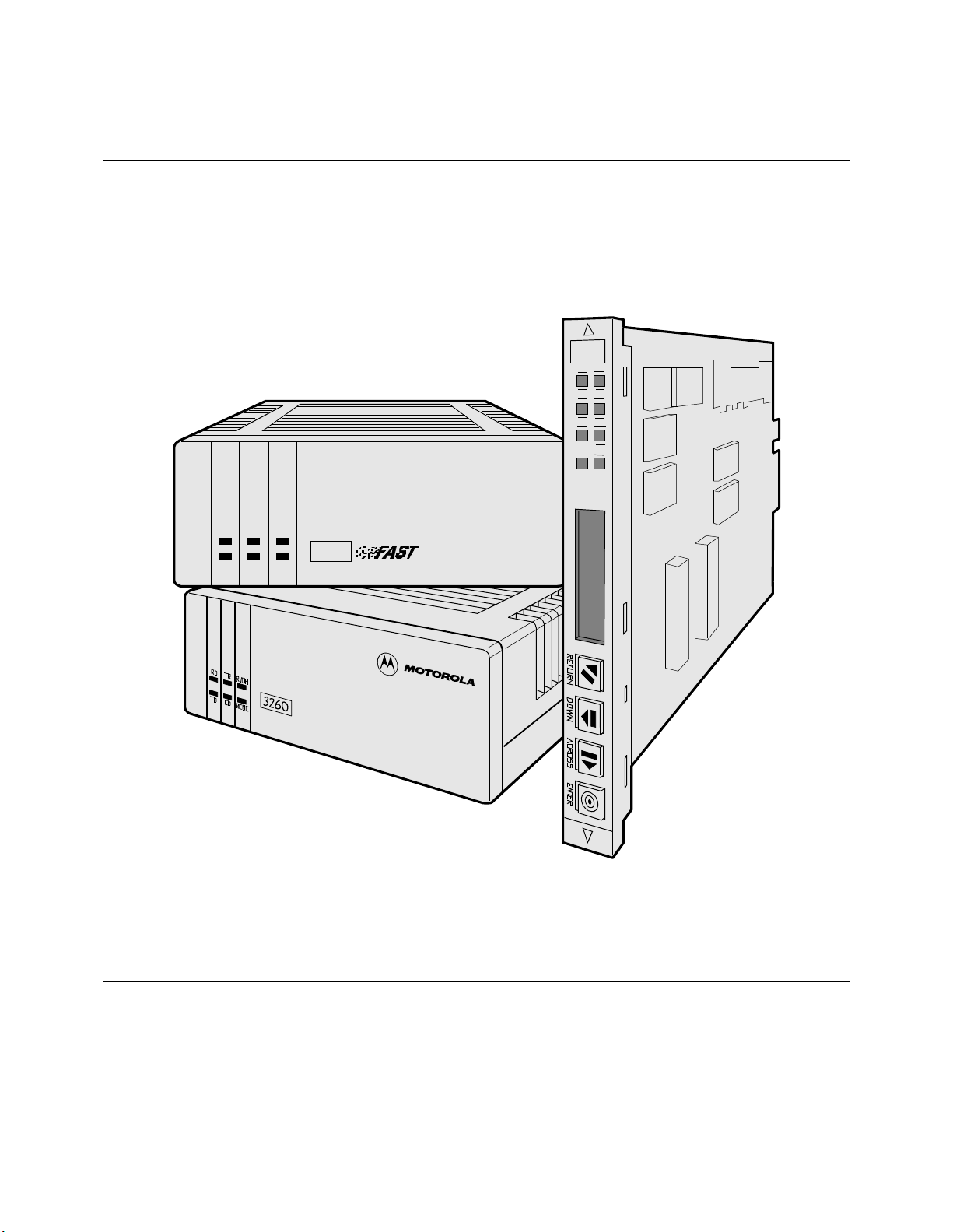
326X V.34, V.34-SDC, and V.32bis
Series Modem User’s Guide
Page 2

Notice
©1998 Motorola, Inc.
20 Cabot Boulevard
Mansfield, Massachusetts 02048
(508) 261-4000
All rights reserved
Printed in U.S.A.
34
Restricted Rights Notification for U.S. Government Users
The software (including firmware) addressed in this manu al is provided to the U.S.
Government under agreement which grants the government the minimum “restricted rights”
in the software, as defined in the Federal Acquisition Regulatio n (FAR) or the Defense
Federal Acquisition Regulation Supplement (DFARS), whichever is applicable.
If the software is procured for use by the Department of Defense, the following legend
applies:
Restricted Rights Legend
Use, duplication, or disclosure by the Government
is subject to restrictions as set forth in
subparagraph (c)(1)(ii) of the
Rights in Technical Data and Computer Software
clause at DFARS 252.227 -70 13 .
If the software is procured for use by any U.S. Government entity other than the Department
of Defense, the following notice applies:
Notice
Notwithstanding any other lease or license agreement that may pertain to,
or accompany the delivery of, this computer software, the rights of the
Government regarding its use, repr odu cti o n, and disclos ure are as set forth
in F A R 52.227 -19 (C ).
Unpublished - rights reserved under the copyright laws of the United States.
Page 3

Notice (continued)
Proprietary Material
Information and software in this document are proprietary to Mo torola, Inc. (o r its Suppliers)
and without the express prior permission of an officer of Motorola, Inc., may not be copied,
reproduced, disclosed to others, publi s hed, or used, in whol e or i n p art , f or any purpose other
than that for which it is being made available. Use of soft ware de scribed in this document is
subject to the terms and conditions of the Motorola Software License Agreement.
This document is for information purposes only and is subject to change without notice.
Radio Frequency Interference Regulations
This equipment has been tested and found to comply with the limits for a Class A digital
device, pursuant to Part 15 of the FCC Rules. These limits are designed to provide reasonable
protection against interference when the equipment is operated in a commercial environm ent.
This equipment generates, uses, and can radiate radio frequency energy and, if not installed
and used in accordance with the instruction manual, may cause harmful interference to radio
communications.
Note: the 3262/63/67/68 Modem is a Class A product. In a domestic environment, this product may cause radio interference, in which case the user may be required to take adequate
measures.
Changes or modifications not expressly appr oved by Motoro la could void the user’s authority
to operate the equipment.
This Class A digital apparatus meets all requirements of the Canadian Interference-Causing
Equipment Regulations.
This is a Class A product. Operation of this equ ip ment in a residential environment may
cause radio interference, in which case the user may b e required to tak e adequate measur es to
correct the interference at his/her own expense.
This product is CISPR 22 Class B verified under test conditions that included use of shielded
DTE cables. Ferrite cylinders attached to the dial line are required for Modem 3266 (Canada). Leased line cables with 1.5 turns through a ferrite cylinder were also used. Use of different cables will invalidate verification and increase the risk of causing interference to rad i o
and TV reception.
You can obtain the proper cables from Motorola.
Page 4

This product is CE marked to indicate compliance with the following European directives.
• 73/23/EEC Low Voltage Directive (Safety)
• 89/336/EEC EEC Directive
Compliance with the above directives may only be assured when the equipment is installed
and operated in accordance with the instructions for its use and the purpose for which it is
intended.
Products that do not bear the CE mark are not intended for supply or use in the European
Union.
Writer: Christina Lamkin
Project Editor: Susan L. Roswit
Publications Specialist: D enise Skinner
Illustrators: Dennis Alves, Tim Kinch
Manual is current for Release 8.0 of the 326X Series Modem.
To comment on this manual, please send e-mail to LAM001@ e mail.mot.com.
Part No. T0009, Rev B
Publication Code: KP
First Printing: April 1996
Page 5

Contents
Restricted Rights Notification for U.S. Government Users ..................... ii
Proprietary Material ................................................................................. iii
Radio Frequency Interference Regulations .............................................. iii
Overview ...................................................................................................... xi
326X Series Modem Family ......................................................................... xi
Product Family Model Numbers .............................................................. xi
Documentation Target Audience .................................................................. xii
Note to Programmers and System Developers ............................................. xii
How to Use the Documentation Set ............................................................. xii
326X V.34 Series Modem User’s Guide (T0009) .................................... xiii
326X Series Modem Reference Guide (09925) ....................................... xiv
References .................................................................................................... xiv
Trademarks ................................................................................................... xiv
Conventions .................................................................................................. xv
Special Notices ............................................................................................. xv
Messages spéciaux ........................................................................................ xvi
Besondere Hinweise ..................................................................................... xvi
Avisos Especiales ......................................................................................... xvii
Introduction .............................................................................................. xix
Questions about Your Product Shipment ................................................. xix
Technical Assistance or Scheduling Service ............................................ xix
Sales-Related Issues ................................................................................. xx
Information on Product Training .............................................................. xx
Questions about Billing ............................................................................ xx
Comments about the Manual ................................................................... xxi
User Documentation ................................................................................. xxi
Customer Response Card ......................................................................... xxiii
Chapter 1. About the Modem
Introduction .................................................................................................. 1-2
Safety and Operational Notices ................................................................ 1-3
Operating the Modem from the Front Panel ................................................. 1-4
Selecting Programmed Option Sets .............................................................. 1-5
Automatic Calling Interfaces (ACUs) .......................................................... 1-5
AT ACU ................................................................................................... 1-5
V.25bis ACU ............................................................................................ 1-5
LPDA2 ACU ............................................................................................ 1-5
Managing a Modem ...................................................................................... 1-6
Restoring Data Transmission ........................................................................ 1-6
ITU-T V.34 Compliant Modulation Mode ................................................... 1-6
Synchronous Data Compression (SDC) Feature .......................................... 1-7
Automode/Multimode Feature ..................................................................... 1-7
Remote Configuration .................................................................................. 1-8
Error Correction and Data Compression ...................................................... 1-8
Security ......................................................................................................... 1-8
Status Snapshots ........................................................................................... 1-8
Adaptive Rate System .................................................................................. 1-9
v
Page 6

Contents (continued)
Troubleshooting (V.54 and V.22bis Tests) .................................................... 1-9
Country-Specific Information ...................................................................... 1-9
NET Compliance .......................................................................................... 1-9
CE Regulatory Marking Directive (93/68/EEC) .......................................... 1-9
Chapter 2. Installing the Modem
Introduction .................................................................................................. 2-2
Unpacking the Modem ................................................................................. 2-3
Additional Equipment Required ................................................................... 2-4
Choosing a Site ............................................................................................. 2-4
Connecting the Modem ................................................................................ 2-5
Rear Panel Connectors ............................................................................. 2-5
Ferrite Cylinders ....................................................................................... 2-7
Cabling the Modem .................................................................................. 2-11
Connecting the Modem to a Network Management System ................... 2-13
Turning on the Modem ............................................................................. 2-14
Automatic Self-Test ...................................................................................... 2-15
After Installing the Modem... ....................................................................... 2-15
Chapter 3. Getting Started
Introduction .................................................................................................. 3-2
System Requirements for Software Upgrades .............................................. 3-2
Configuring and Operating the Modem .............................................. ......... 3-2
Using the Front Panel ............................................................................... 3-2
Navigating the Configuration Menu Tree ................................................ 3-5
Setting Configuration Options from the Front Panel ............................... 3-5
Using the Modem with a Network Management System (NMS) ............ 3-7
Using the AT Automatic Calling Unit (ACU) .......................................... 3-8
Other Call Establishment Methods ............................................................... 3-10
V.25bis ACU for Sync or Async Applications ......................................... 3-10
NetView LPDA-2 ACU for Sync Applications ....................................... 3-10
Sync Dialing from an IBM AS 400 .......................................................... 3-11
External Auto-Call Units .......................................................................... 3-11
Chapter 4. Configuring the Modem
Overview ...................................................................................................... 4-2
Communications Software Package Operating Notes .................................. 4-2
Configuring the Modem for Use with Communications
Software ............................................................................................... 4-2
Operating Notes ....................................................................................... 4-3
If the Communications Software and Modem Do Not Operate... ............ 4-5
Preparing for Operation ................................................................................ 4-5
Reinitializing Memory from the Front Panel ........................................... 4-5
vi
Page 7

Contents (continued)
Reinitializing Memory Using the AT&F Command ................................ 4-5
Configuration Option Sets ............................................................................ 4-6
What is an Option Set? ............................................................................. 4-6
Configuring an Option Set ....................................................................... 4-10
Option Set Defaults .................................................................................. 4-12
326X V.32bis and 326XFAST Modem Application Examples .................... 4-18
Option Set 1—Async Calls to Central Site Using AT ACU .................... 4-19
Option Set 2—Sync Answering Central Site Without ACU .................... 4-20
Option Set 3—Sync Calls to Central Site, V.25bis ACU ......................... 4-20
Option Set 4—Async Answering Central Site without ACU (Models 3260/62/65/67)
4-21
Option Set 4—Synchronou s Leased Line Applications wit h Dial Restor al (Models
3261/63/66/68) ..................................................................................... 4-22
326XFAST-SDC Modem Application Examples ......................................... 4-22
SDC Pre-Operation Notes ........................................................................ 4-23
Configuring the Modem for SDC Operation ........................................... 4-23
SDC Sample Applications ........................................................................ 4-24
Remote Access Reset ................................................................................... 4-29
Operation .................................................................................................. 4-29
When Remote Access Reset Is Disabled ................................................. 4-29
Chapter 5. Using the AT Automatic Calling Interface
Introduction .................................................................................................. 5-2
What is the Attention (AT) Command Set? .................................................. 5-3
What Role Does Communications Software Play? .................................. 5-3
Using AT Commands ............................................... ......... ........................... 5-3
Entering AT Command Lines ................................................................... 5-3
Autobaud Feature ..................................................................................... 5-5
The Escape Sequence—(+++) ................................................................. 5-5
Non-Configuration AT Commands .......................................................... 5-6
S-Registers ............................................................................................... 5-9
Chapter 6. Troubleshooting Guide
Introduction .................................................................................................. 6-2
Troubleshooting ............................................................................................ 6-2
326X Series Modem Diagnostic Tests .......................................................... 6-10
Synchronous Data Compression (SDC) Testing ...................................... 6-11
Appendix A. Configuration Quick Reference
Configuration Quick-Reference—Menu Trees ............................................ A-2
For More Detail ........................................................................................ A-2
Audience and Assumptions ...................................................................... A-2
Performing Numeric Entry ........................................................................... A-37
vii
Page 8

Contents (continued)
S-Register/AT Command Cross-Reference .................................................. A-38
Dial Modifiers for Special Dialing Requirements ........................................ A-39
Result Codes ................................................................................................. A-41
Configuring the Modem’s Dual In-line Package (DIP) Switches ................ A-44
Appendix B. Cabling and Interface Pinouts
Introduction .................................................................................................. B-2
EIA/TIA 232-D (Modem to Computer) Interface ........................................ B-2
ITU Recommendation V.35 Modem-to-Computer Interface ....................... B-4
ITU Rate V.35 Modem-to-Computer Interface Pinouts ........................... B-5
Differences, EIA/TIA 232-D and ITU Rate V.35 Interfaces .................... B-6
DIAL LINE, LEASE (PRIVATE) LINE, PHONE Connector Pinouts ........ B-6
NC (Network Control) Port Pinouts ............................................................. B-7
Cabling ......................................................................................................... B-7
Cable Considerations ............................................................................... B-7
DTE Cable Diagnostics ............................................................................ B-10
Appendix C. Country-Specific Information
Introduction .................................................................................................. C-3
Country Support ....................................................................................... C-3
Installation Notes .......................................................................................... C-4
Restricted Features Summary ....................................................................... C-4
Operating Notes ............................................................................................ C-12
Standalone Modem Rear Panel Views .......................................................... C-12
3260 Dial Only Modem ........................................................................... C-13
3261 Modem Rear View (Leased Line, Dial Restoral) ............................ C-13
3265 Dial Only Modem ........................................................................... C-14
3266 Modem (Leased Line with Dial Restoral) ....................................... C-16
Rear Panel Interface Pinouts ........................................................................ C-18
Standalone Models 3260/65 and 3261/66 Interface Pinouts .................... C-18
Card Models 3262/67, 3263/68 Backplane Interface Pinouts .................. C-21
Delayed and Forbidden Lists ........................................................................ C-23
Australia—Delayed Call Lists ................................................................. C-23
Austria—Forbidden Call Lists ................................................................. C-23
Belgium—Delayed Call Lists .................................................................. C-24
Finland—Delayed Call Lists .................................................................... C-25
France—Delayed and Forbidden Call Lists ............................................. C-25
Hong Kong—Delayed Call Lists ............................................................. C-26
Ireland—Delayed Call Lists ..................................................................... C-26
Netherlands—Delayed Call Lists ............................................................. C-27
Norway—Delayed Call Lists ................................................................... C-27
Spain—Delayed Call Lists ....................................................................... C-28
Other Country-Specific Information ............................................................ C-28
Canada .......................................................................................................... C-28
DOC Registration and Requirements ....................................................... C-28
viii
Page 9

Glossary
Return Procedures
Contents (continued)
Industry Canada Equipment Attachment Limitations .............................. C-29
Canadian Emissions Statement ................................................................ C-29
Rear Panel Pinouts ................................................................................... C-30
Telco Option (AT&J) ................................................................................ C-31
Denmark—Blind Dialing ............................................................................. C-32
Hong Kong and United Kingdom—BABT Regulations .............................. C-32
Compliance with BS6328: Part 1: 1982 Section 8.3 ................................ C-32
Compliance with BS6328: Part 1: 1982 Section 8.7 ................................ C-32
Compliance with BABTSITS/82/01/C and BABT/SITS/82005S/D ....... C-33
Compliance with BS6305 Clause 6.2, BS6320 Clause 7.2 ...................... C-33
Ringer Equivalence Number (REN) ........................................................ C-33
Compliance with BABT/SITS/83/08/A Clause 1.2 ................................. C-34
Compliance with BS6789: Section 6.1:1986 Clause 5.2 ......................... C-34
Compliance with BS6789: Section 6.1:1986 Clause 7.3.1.3 ................... C-34
Compliance with BS6789: Section 6.1:1986 Clause 7.3.1.4 ................... C-34
Compliance with DTI 83/009I ................................................................. C-35
Compliance with BS6301 ........................................................................ C-35
Compliance with BABT SITS 83/009 Section D .................................... C-35
Installation of Telephone Socket .................................................................. C-36
Application for Installation of Telephone Socket ......................................... C-36
U. S. A. ......................................................................................................... C-36
FCC Registration ...................................................................................... C-36
FCC Regulations ...................................................................................... C-37
Dial Line Jack Types ................................................................................ C-38
Rear Panel Pinouts ................................................................................... C-39
Dial and Leased Line Transmit Levels .................................................... C-41
Making Telephone-to-Modem Connections ............................................. C-41
Telco Option (AT&J) ................................................................................ C-41
Declaring The Jack Type .............................................................................. C-42
Using the Modulus Backplane’s Busy Out Feature ...................................... C-43
Equipment Return Procedures ...................................................................... ret-2
Expiration of Lease .................................................................................. ret-2
Factory Repair ............................................. ......... .................................... ret-2
Packaging Guidelines for Equipment Return ........................................... ret-2
ix
Page 10

Contents (continued)
x
Page 11

Overview
The 326X product documentation set includes the 326X V.34 Series Modem Reference Card (T0009- 01) .
Optionally, with a 326X Series Modem card backplane (to install a 326X card into a
Modulus 9 or 21 enclosure), you receive the following:
• 326X Series Modem Cards (Part No. 09949)
Throughout this guid e, references to the 326X Ser ies Modem apply to 326X V.32bis,
326X V.34, and 326X-SDC Series Modems, unless stated otherwise.
326X Series Modem Family
The 326X product family consists of three series: V.34, V.34 SDC, and V.32bis.
Using the Documentation Set
Supports This
This Series...
326XFAST V.34 ITU V.34 33.6 kbps 128 kbps, asynchronous
326XFAST-SDC ITU V.34 33.6 kbps 128 kbps, asynchronous, and,
326X ITU V.32bis 14.4 kbps 57.6 kbps, asynchronous
IMPORTANT: When you select a modulation mode, you must ensure that the Max
Rate (A T*MX) and Mi n Ra te (AT*MN) p arame te r options are within the v ali d r ange
for the mode .
Some 326XFAST-SDC models are available with a V.35-compatible interface. This
unit has a DB25 connector, so a converter is required.
Modulation...
This Maximum
DCE Rate...
And This Maximum
DTE Rate:
with proprietary compression,
128 kbps synchronous
Product Family Model Numbers
Motorola refers to the product family as 326X because the last digit denotes the
modem model. Model numbers (“X”) are as follows.
This Model Number... Denotes:
3260, 3261, 3262, 3263 Models for use in the U.S.A.
3265, 3266, 3267, 3268 Equivalent models, respectively, for international use;
provided in country-specifi c setup s
3260, 3265 Standalone models for:
• Two-wire dial operation
• Two-wire leased-line operation
xi
Page 12

Using the Documentation Set (continued)
This Model Number... Denotes:
3261, 3266 Standalone models for:
• Two-wire dial opera tion
• Two- or four-wire leased-line operation
3262, 3267 Rack-mount dual-modem card models, equivalent to 3260
and 3265, respectively, for Modulus enclosure installation
3263, 3268 Rack-mount single-modem card models, equivalent to 3260
and 3265, respectively, for Modulus enclosure installation
Documentation Target Audience
The documentation set assumes that you are familiar with the basic concepts of data
communications, that you are an oper ator o nly, and that you will not be servic ing th e
modem hardware (other than making initial cabling connections).
Note to Programmers and System Developers
For detailed information on configuration options, equivalent AT Commands, V.25
bis Automatic-Calling Unit, NetView’s LPDA-2 dialing commands, or diagnostic
tests, order the 326X Seri es Mode m Ref erence Guide (Part No. 09925) by contac ti ng
your Motorola sales representative or local distributor.
How to Use the Documentation Set
Following is a description of the 326X Series Modem documentation set.
326X V.34 Series Modem Reference Card (T0009-01)
For a quick reference to AT, AT&, and AT* commands, dial modifiers, and
disconnect codes, see the 326X V.34 Series Modem Reference Card. The card also
includes a menu tree of front panel options and AT command settings.
xii
Page 13

Using the Documentation Set (continued)
326X V.34 Series Modem User’s Guide (T0009)
This User’s Guide provides the information nee d ed t o in stall, configure , an d oper ate
the modem. Chapter outlines are as follows:
Chapter 1, About the Modem, introduces the modem’s features.
Chapter 2, Installing the Modem, explains how to install and cable a modem.
Quick-reference figures showing the connections to make are included.
Chapter 3, Getting Started, discusses how the modem can be used, and
recommends how to configure and operate it. The chapter includes a reference
guide to the rest of the documentation set for further information.
Chapter 4, Configuring the Modem, explains how to effectively configure the
modem. The four preconfigured option sets are described, along with sample
applications that help you choose an option set.
Chapter 5, Using the A T Automatic Calling Interface, discusses the 326X Series
Modem’s AT ACU. This chapter introduces:
• The ACU industry-standard (AT and AT&) commands
• The Motorola enhanced AT command syntax (AT*).
• The AT commands th at are referred to as “action” AT commands (rather than
“configuration” AT commands), and S-Register functions and settings
Chapter 6, Troubleshooting Guide, is a quick reference to problems and
suggestions for correcting them. This chapter assists you in isolating and
correcting a problem before calling Motorola’s Customer Support Center.
Appendix A, Configuration Quick Reference, provides reference material you
need to change a modem’s default settings. It describes:
— Configuration options wi th and without AT equivalents
— Result codes (long and short forms)
— S-Registers
— Dial modifiers
— Numeric entry procedure
— The configuration menu structure
Appendix B, Cabling and Interface Pinouts, contains the pinouts for the
modem’s rear panel connectors and associated cables.
Appendix C, Country-Specific Information, discusses the cabling, rear panel
layouts, pinouts and other modem features that are required or restricted by
regulatory agencies for each country.
xiii
Page 14

Using the Documentation Set (continued)
326X Series Modem Reference Guide (09925)
Available as an optional order item, the 326X Series Modem Reference Guide is
designed for users who require more detail on operating the modem’s configuration
options and diagnosti c self -tes ts. Co ntact your Motorol a sale s repre senta tive or local
distributor for ordering information.
References
Refer to the following documents for more information:
• 326X, 326XFAST, and 326XFAST-SDC Series Modem Product Specification
Sheets
• EIA Application Note #562, Appendix A (defines cable lengths in terms of
DTE rates)
NetView operators should be familiar with:
• NetView Operations Primer (IBM Part No. SC30-3363)
Trademarks
• NetView Operation Scenarios (IBM Part No. SC30-3376)
The following are tr adema rks or r egist ered t rademar ks of t heir r esp ectiv e companie s
or organizations:
AT is a command language used with the Smartmodem 1200 and the
Smartmodem 2400/Hayes Microcomputer Products, Inc.
CompuServ / CompuServ Inc.
MNP (Microcom Networking Protocol) and Relay Gold / Microcom, Inc.
NetView and IBM / International Business M achines Corporatio n
Novell and NetWare / Novell, Inc
Telenet / Sprint International Communications Corporation
Tymnet / British Tele communications
UNIX / Unix System Laboratories
xiv
Page 15
Conventions
Using the Documentation Set (continued)
The following conventions are used in this manual:
Special Notices
These notices emphasize certain information in the manual. Each serves a special
purpose and is displayed in the format shown.
IMPORTANT: Important is used to emphasize any significant procedural
information.
• User entries appear as follows: AT
• System messages appear as follows:
• A carriage return appears as follows: <CR>. It desig nates the Return or E nter
key. It is used to complete a text entry or initiate an action from the keyboard.
T<CR>
*
NO CARRIER
Caution
Caution provides information that, if not followed, can result
in damage to software, hardware, or data.
Warning
Warning is the most serious notice, indicating that you can be
physically hurt.
xv
Page 16
Messages spéciaux
Les messages suivants mettent en valeur certaines informations dans le guide. Cha-
cun d’eux remplit une fonction spéciale et est affiché dans le format indiqué.
IMPORTANT: Important est utilisé pour souligner des informations critiques au
sujet d’une procédure.
Mise en Garde
Une mise en garde vous fournit des informations qui, si elles
ne sont pas observées, peuvent se traduire par des dommages
pour le logiciel, le matériel ou les données.
Avertissement
Un avertissement constitue le message le plus sérieux, indiquant que vous pouvez subir des blessures corporelles.
Besondere Hinweise
Durch die folgenden Hinweise werden bestimmte Informationen in diesem Handbuch hervorgehoben. Jeder
Hinweis dient einem bestimmten Zweck und wird im dargestellten Format angezeigt.
WICHTIG: Wichtig wird zur Betonung signifikanter Angaben zu Vorgehensweisen
verwendet.
Vorsicht
Ein Vorsichtshinweis macht Sie darauf aufmerksam, daß Nichtbefolgung zu Software- , Hardware- oder Datensc häden führen
kann.
Warnung
Eine Warnung weist Sie darauf hin, daß ernsthafte Körperverletzungsgefahr besteht.
Page 17
Avisos Especiales
Los siguientes avisos hacen hincapié en determinada información de la guía.
Cada uno de ellos tiene un propósito especial y aparecen con el formato siguiente:
IMPORTANTE: Importante se utiliza para enfatizar cualquier información de pro-
cedimiento importante.
Using the Documentation Set (continued)
Precaucion
La precaución le ofrece información, que de no cumplirse,
puede derivar en posibles daños tanto para el software y el
hardware, como para ambos.
!
Advertencia!
Una advertencia es un aviso importante, que le advierte sobre
la presencia de un inminente peligro.
xvii
Page 18

Using the Documentation Set (continued)
xviii
Page 19

Motorola Information System Group (ISG)
Introduction
U.S.A. customers who have questions about Motorola ISG products or services
should refer to the following sections. Non-U.S.A. customers should contact their
local Motorola ISG subsidiary office or distributor.
Questions about Your Product Shipment
If you have questi ons about whether your shi pment is comple te or a bout its c ondition
upon receipt, please call your nearest Motorola ISG representative or Customer
Administration at (508) 261-4000, Extension 4745.
Technical Assistance or Scheduling Service
To have Motorola ISG implement your equipment:
You can purchase and schedule Implementation Services by calling (800) 544-0062
(from within the U.S.). The averag e lead time for implem entation services is 5
business days from the time of the call. Implementation services include running
power-up diagno stics, confi guring the equip ment, and con necting the equi pment into
existing networks. A servi ce engineer wil l be dispatched to your site to perform the se
services.
Customer Information
If you implement your equipm ent yourself:
Carefully follow the instructions in the following sections of this documentation set:
To install and power up - Chapter 2.
To configure and operate - Chapter 3.
If you have difficulty - Chapter 6 provides a quick reference to problems you
may encounter, and suggestions for correcting them.
xix
Page 20
Motorola ISG Customer Information
(continued)
For service, if your unit is under warranty and/or you have a service contract:
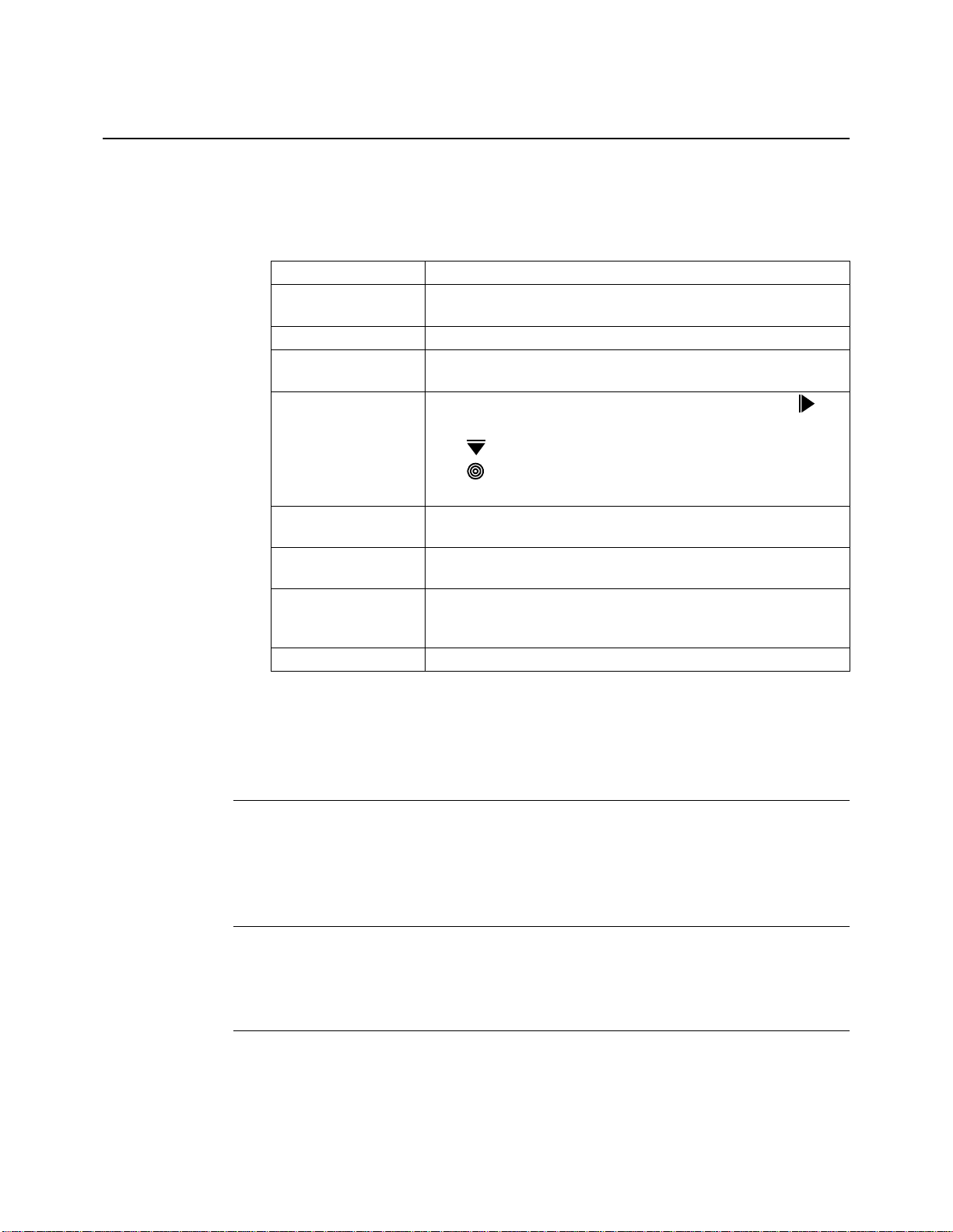
Call (800) 544-0062 for assistance. When you call, please have the following information rea dy :
Item Location or Description
Model number Front of unit. 3260, 3261, 3262, 3263, 3265, 3266, 3267, 3268.
(For synchronous data compression models, specify SDC.)
Serial number Bottom of standalone unit; edge of card unit.
Error message/
Problem Description
Software revision LCD Display: from [Modulation Mode] 9600 T/D? press to
Option Settings Up-to-date configu rati on worksheet (see the 326X Series Modem
Site ID Assigned to the customer site by Motorola at first service call.
Application type Leased line with or without dial restoral or dial. Also specify the
Connected hardware DTE type(s): asynchronous or synchronous terminal or PC.
LCD Display.
display the operating status. (Example: DTE 19.2 RELIABL.)
Press until Display Modem ID displays.
Press . SWPart=x displays.
The rightmost two digits show the revision level.
Reference Guide).
Customer should store the ID, once assigned.
data transfer protocol: asynchronous, direct-synchronous, or
synchronous data compression (SDC) mode.
xx
If you do not have a service contract, and your unit is no longer under warranty:
You can purchase a service contract or arrange for Time and Material services by
calling (800) 544-0062 for assistance.
Sales-Related Issues
Please call your local Motorola ISG sales office, authorized distributor, or the Sales
Assistance Center at (800) 487-1456. For a listing of our Sales Offi ces, visit our Web
site at: http://www.mot.com/MIMS/ISG/.
Information on Product Training
For information on classroom training, customized on-site training, or to order
self-study training materials, call the Sales Assistance Center at (800) 487-1456.
Questions about Billing
If you have a question regarding billing, call (800) 446-0144 and select option 2.
Page 21

Motorola ISG Customer Information
(continued)
Comments about the Manual
To help us improve our product documentation, please complete and return by mail,
or fax to (508) 339-6814, the prepaid comment card on the next page. If you prefer,
simply include your name, company, and telephone number and a member of the
documentation group will contact you to discuss any comments you might have.
User Documentation
To order Motorola ISG user documentation, call (508) 261-7056.
xxi
Page 22

Motorola ISG Customer Information
(continued)
xxii
Page 23
Customer Response Card
Motorola would like your help in improving its product documentation. Please complete and return this
card (by mail or fax to (508) 339-9592; Attention: Product Documentaton), to provide your feedback.
To discuss comments with a member of the Motorola documentation group, provide telephone
information at the bottom of this page. Thank you for your help.
Name _________________________________________________________________________
Company Name _________________________________________________________________
Address _______________________________________________________________________
_______________________________________________________________________
_______________________________________________________________________
Document Title: 326x v.34, V.34-SDC, and V.32bis Series Modem User’s Guide
Part Number: T0009, Rev B
Please rate this document for usability:
Excellent Good Average Below Average Poor
What did you like about the document? ______________________________________________
______________________________________________________________________________
______________________________________________________________________________
Cut Here
______________________________________________________________________________
______________________________________________________________________________
What information, if any, is missing from the document? _________________________________
______________________________________________________________________________
______________________________________________________________________________
______________________________________________________________________________
______________________________________________________________________________
Please identify any sections/concepts that are unclear or explained inadequately.
______________________________________________________________________________
______________________________________________________________________________
______________________________________________________________________________
______________________________________________________________________________
Additional comments/suggestions. __________________________________________________
______________________________________________________________________________
______________________________________________________________________________
______________________________________________________________________________
______________________________________________________________________________
Telephone ________________________ Ext. _________________ Best time to call __________
Page 24

FOLD HERE
DO NOT TEAR – FOLD HERE AND STAPLE
BUSINESS REPLY MAIL
FIRST CLASS PERMIT NO. 39783 MANSFIELD, MA
POSTAGE WILL BE PAID BY ADDRESSEE
34
Motorola University East M3-30
20 Cabot Boulevard
Mansfield, Massachusetts 02048-1193
USA
NO POSTAGE
NECESSARY
IF MAILED
IN THE
UNITED STATES
Page 25

Chapter 1
About the Modem
Contents
Introduction .................................................................................................. 1-2
Operating the Modem from the Front Panel ................................................. 1-3
Selecting Programmed Option Sets .............................................................. 1-4
Automatic Calling Interfaces (ACUs) .......................................................... 1-4
AT ACU ................................................................................................... 1-4
V.25bis ACU ............................................................................................ 1-4
LPDA2 ACU ............................................................................................ 1-5
Managing a Modem ...................................................................................... 1-5
Restoring Data Transmission ........................................................................ 1-5
ITU-T V.34 Compliant Modulation Mode ................................................... 1-6
V.34 Modulation Mode Characteristics ............................................... 1-6
Compatibility in V.34 Modulation Mode ............................................. 1-6
Synchronous Data Compression (SDC) Feature .......................................... 1-6
Automode/Multimode Feature...................................................................... 1-7
Remote Configuration .................................................................................. 1-7
Error Correction and Data Compression ...................................................... 1-7
Security ......................................................................................................... 1-7
Status Snapshots ........................................................................................... 1-7
Adaptive Rate System ................................................................................... 1-8
Troubleshooting (V.54 and V.22bis Tests) .................................................... 1-8
Country-Specific Information ...................................................................... 1-8
NET Compliance........................................................................................... 1-8
CE Regulatory Marking Directive (93/68/EEC)........................................... 1-8
About the
Modem
About the Modem 1-1
Page 26

Introduction
Modem
About the
This chapter summarizes the features and options of the 326X Series Modem. The
series includes:
• The 326X V.32bis Series Modem, which operates in V.32bis modulation mode
• The 326XFAST Series Modem, which can operate in V.34 modulation mode
• The 326XFAST-SDC Series Modem, which can operate in V.34 modulation
mode and the Synchronous Data Compression mode
In this guide, references to the modem apply to all of the above, unless stated
otherwise.
IMPORTANT: When you select a modulation mode, you must ensure that the Max
Rate (A T*MX) and Mi n Ra te (AT*MN) p arame te r options are within the v ali d r ange
for the mode .
The modem provides reliable data communication over 2-wire dial lines and 2-wire
or 4-wire leased lines, depending on the model. Dial lines are public lines to which
all telephone users have access; leased lines, also called private lines, provide a
dedicated connection, over lines provided by the telephone company.
Whether you use dial or leased lines, you can operate the modem as follows:
• Using the front panel: control keys and liquid-crystal display (LCD)
• Using industry-standard (AT and AT&), and Motorola-enhanced (AT
commands from an attached terminal, or commands from an asynchronous
communications software package running on an attached PC
•From a network management system (NMS)
• Using call establishm ent methods, such as V.25bis or LPDA2 automatic call
units (ACUs)
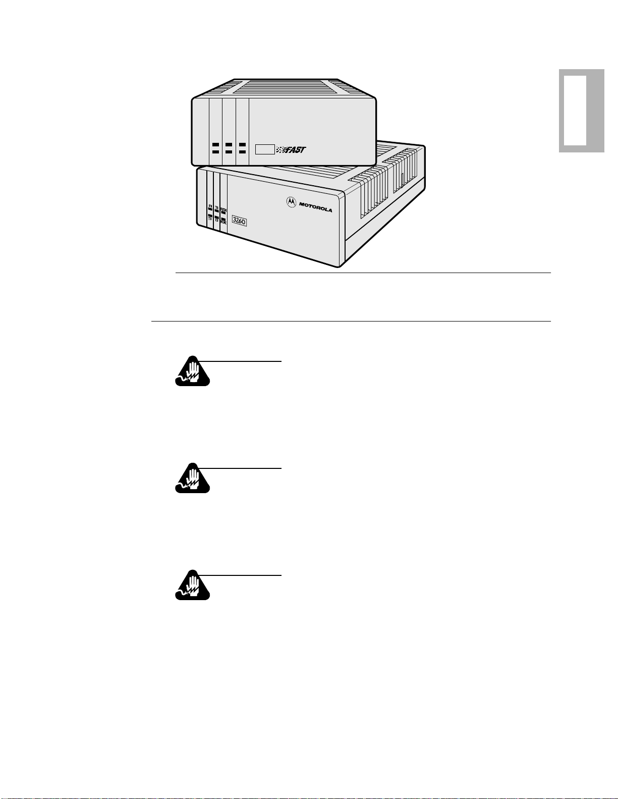
Figure 1-1 shows desktop, or standalone, modems. The device is also available in
high-density nest cards, which offer the same features, and can be installed in
Motorola’s Modulus 9-slot and Modulus 21-slot rack-mounted enclosures.
*
) AT
1-2 About the Modem
Page 27
34
About the
Modem
RD TR RI/OH
TD CD RC/NC
3260
Figure 1-1. 326X Series Modem, Standalone Desktop Model
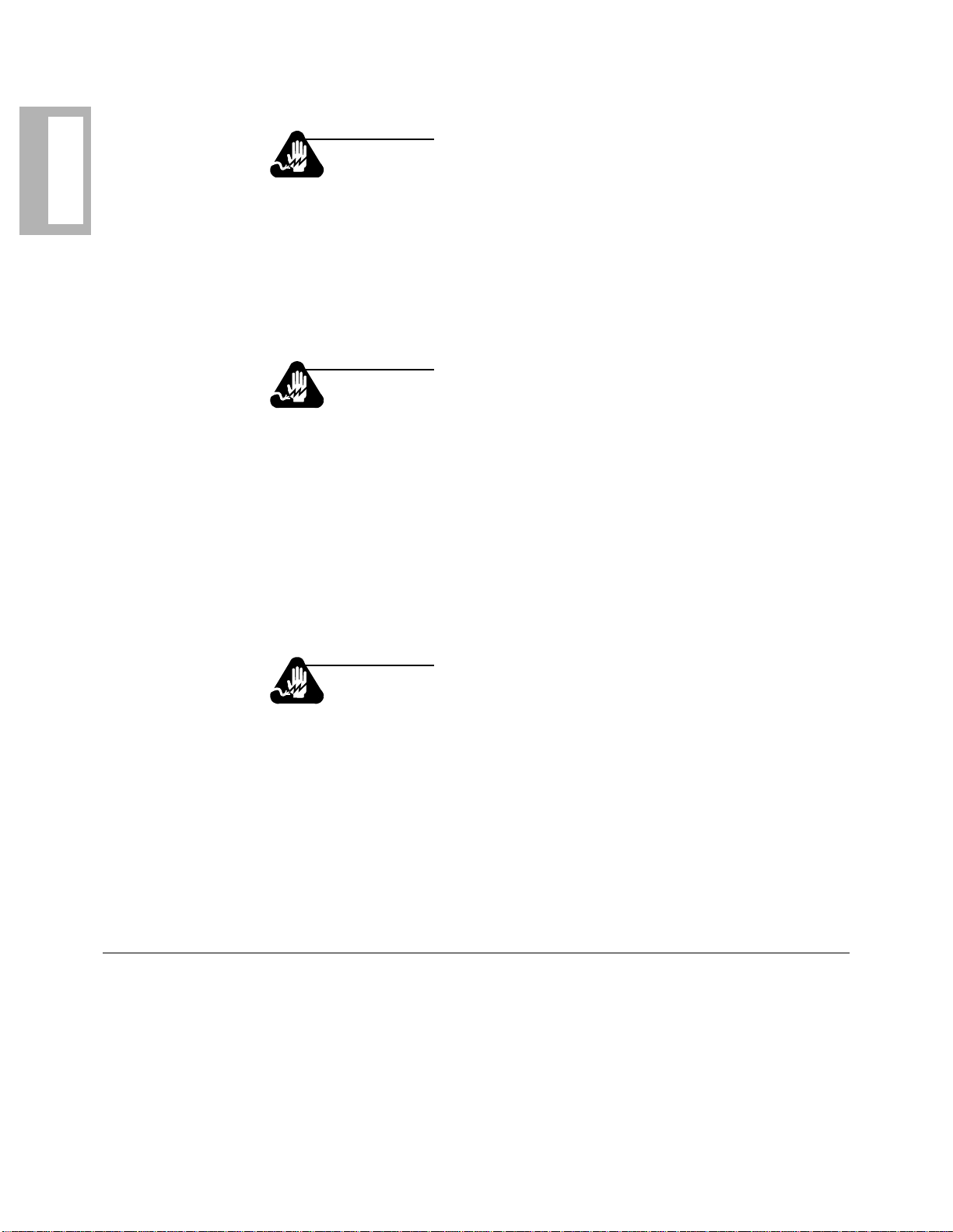
Safety and Operational Notices
Repair
Warning
Do not attempt to repair the modem or enclosure. They contain no
electronic components that can be serviced or replaced by a user.
Any attempt at user service of the 3460 Fast’R or AccessWay
enclosure, or opening of the 3460 Fast'R unit, voids the produ ct
warranty.
Ave rtissement
N’essayez pas de réparer le modem ou le boît ier. Ils ne contiennent
aucun composant électron ique pouvant êtreréparé ou re mp la cé pa r
un usager. Toute tentative de réparation du boîtier du 3460 Fast’R
ou de l’AccessWay 16par un usager, ou toute intervention à
l’intérieur du 3460 Fast’R, annule la garantie du produit.
Warnung
Versuchen Sie nicht, das Modem oder sein Gehäuse zu reparieren.
Es sind keine durch den Benutzer wartungs- oder austauschfähige
Teile darin enthalten. Bei jeglichem Öffnen oder Wartungsversuch
am 3460 Fast'R bzw. AccessWay 16-Schaltkasten durch den
Benutzer verfällt die Gerätegarantie.
About the Modem 1-3
Page 28
Modem
About the
Lightning
Warning
All Motorola devices should be used in en vir onments designed for
computers and electronic equipment. In areas susceptible to lightning, take precautions to prevent damage to electronic equipment.
Contact your telephone company, or an electronic accessories vendor, f or i nf o rma ti on on li ght ni ng protection equipme nt. Customers
experiencing problems caused by surges from lightning have eliminated such problems by installing appropriate surge suppressors
on power and data lines connected to Motorola devices.
Avertissement
Tous les dispositifs Motorola doivent être utilisés dans des environnements conçus pour des ordinateurs et du matériel électronique. Dans les zones susceptibles d’être frappées par la foudre,
prenez des précautions pour éviter que le matéri el électron ique soit
endommagé. Contactez votre compagnie téléphonique, ou un vendeur d’accessoires électroniques, pour obtenir des renseignements
concernant les systèmes de protection contre la foudre. Certains
usagers confrontés à des problèmes causés par des sautes de tension dues à la foudre ont éliminé ces problèmes en installant des
régulateurs de tension appropriés sur les câbles électriques et les
câbles de données reliés aux dispositifs Motorola.
Warnung
Motorola-Geräte sind grundsätzlich in für Rechner und elektronische Anlagen vorgesehenen Umgebungen zu verwenden. In
unwettergefährdeten Bereichen ist jegliche Elektronik gegen
Blitzeinwirkung zu schützen. Näheres über entsprechende
Schutzeinrichtungen erfahren Sie von Ihrer Telefongesellschaft
oder einem Elektrohändler. Probleme mit Spannungsstößen durch
Blitzeinwirkung lass en sic h durch Ei nbau von Überspa nnungsab leitern in die zu Motorola-Geräten führenden Netz- und Datenleitungen beheben.
Operating the Modem from the Front Panel
The front panel menus ar e or ganized f unctiona lly so t hat o peration is easy for novice
and advanced users.
Refer to Chapter 3, Getting Started, to learn about front panel operation.
1-4 About the Modem
Page 29

Selecting Programmed Option Sets
Option sets make it easy to use a modem with common applications, including:
• Asynchronous and synchronous answering
• Asynchronous and synchronous dialing
• Leased line with dial restoral operation
Four sets of options are stored in nonvolatile memory. If none is appropriate to an
application, you can customize an option set, and save it in nonvolatile memory.
Refer to Chapter 4, Configuring the Modem, for more information on option sets.
Automatic Calling Interfaces (ACUs)
The modem supports three automatic calling interfaces (also known as Auto-Call
Units). ACUs let you execute functions directly from a keyboard.
AT ACU
The asynchronous AT ACU is compatible with the industry-standard AT command
set. AT Commands provide a standard modem communications interface, allowing
you to configure and operate your modem from a terminal or PC keyboard.
About the
Modem
Using the AT-compatible command set (AT and AT&), you can, for example, dial
and receive phone ca lls. Motorola ’s extended AT command set (AT
important parameters used in configuring advanced modem features.
Refer to Chapter 3, Getting Started, and Chapter 5, Using the AT Automatic Calling
Interface, to learn more about the AT ACU and AT command syntax.
) includes other
*
V.25bis ACU
For sync or async auto-calling, use the ITU-T V.25bis compliant ACU.
With either the AT or V.25bis ACU, you can store, dial, or change up to nine phone
numbers in the modem's electronic telephone book, directly from your terminal.
Refer to Chapter 3, Automatic Calling Interfaces, in the 326X Series Modem
Reference Guide, for details .
LPDA2 ACU
The LPDA2 feature lets you use IBM dial and leased line restoral applications with
LPDA2 Dial and Disconnect commands. LPDA2 allows Netview and other IBM
applications, like POS outbound dialing applications, to control dialing.
In dial applications, LPDA2 eliminates the need for additional ports and equipment
that had been required to support external 801 auto-dialing equipment in IBM
environments.
About the Modem 1-5
Page 30

Modem
About the
Managing a Modem
In leased line operati on, while conn ected on the dial line, the modem can monitor for
LPDA2 commands in the data stream. If the local modem detects an LPDA2
command, the frame that is being processed is aborted. This prevents the remote
DTE from processing the command frame as valid data.
Refer to Chapter 3, Automatic Calling Interfaces, in the 326X Series Modem
Reference Guide, for details .
Integral Network Management by Motorola’s 9110, 9000-UX, and 9000-PC
Network Management Systems (NMS) is standard. The NMS can configure, monitor, and control local and remote modem operation.
An NMS continuously polls modems to collect management information and check
status. Network management traffic, including alarms, commands, events, and
polling, is transp orted to re mote modems on a n in- band cha nnel t hat d oes not disr upt
user data traffic nor consume user bandwidth. The modem supports a daisy-chain
network management interface, reducing the hardware required for connections.
Refer to Chapter 2, Installing the Modem, for instructions on installing and cabling a
modem for use with Motorola’s Network Management Systems.
Restoring Data Transmission
For critical leased line applications that require backup, you can use Models 3261,
3263, 3266, or 3268 in a point-to-point configuration. If the leased line fails, these
modems can automaticall y reroute dat a traf fi c through the public swit ched teleph one
network (PSTN) over a 2-wire dial line. This integral dial line restoral feature
guarantees that data will keep flowing, minimizing network downtime.
ITU-T V.34 Compliant Modulation Mode
326XFAST and 326XFAST-SDC modems support the ITU-T V.34 compliant
modulation mode. 326XFAST- SDC modems offer the same broad set of features
available in the 326XFAST modems, and let you take advantage of faster
transmission speeds while providing highly reliable data transmission in full-duplex
synchronous environments.
326XFAST modems have a line probing featu re tha t opt imizes perfo rmance o n ever y
connection by automatically choosing the optimum bandwidth, carrier frequency,
and data rate.
V.34 Modulation Mode Characteristics
V.34 modulation mode characteristics are as follows.
1-6 About the Modem
Page 31

Data Rate: 2.4, 4.8, 7.2, 9.6, 12.0, 14.4, 16.8, 19.2, 21.6, 24.0, 26.4, 28.8, 31.2, and
33.6 kbps
Baud Rate: 2400, 2743, 3000, 3200, and 3429. Some baud rates do not support all
data rates.
Carrier Frequency: 1600, 1646, 1800, 1829, 1920, 1959, and 2000 Hz. Some baud
rates do not support all carrier frequencies.
Modulation: V.34 is a four-dimensional trellis-coded modulation standard that uses
precoding and pre-emphasis equalization schemes.
Compatibility in V.34 Modulation Mode
326XFAST Series Modems (operating in V.34 Auto modulation mode), are
compatible with modems that do not support the V.34 modulation mode, by
automatically negotiating the highest common modulation mode (e.g., V.32bis).
V.90 Compatibility: Release 8.1 software enables 326X modems to operate with
V.90 modems in dial-up connection s. With this softwar e, 326X modems can communicate with V.90 modems and negotiate V.34 rates. The release does not provide
56kbps rates for 326X modems, nor 326X rates higher than the V.34 33.6 kbps standard. An upgrade to 8.1 is not required for modems used only in leased-line applications.
About the
Modem
Synchronous Data Compression (SDC) Feature
The 326XFAST Series Modem is available in a synchronous data compression
(SDC) model. 326XFAST products offer all the features of the 326XFAST family,
plus synchronous DTE rates at 72.0 kbps or higher.
The 326XFAST-SDC Modem is an ideal alternative to costly digital services.
Whether your application requires dedicated bandwidth, bandwidth on demand,
synchronous dial-up, or dial backup, the 326X-SDC provides optimum throughput
for all HDLC/SDLC-like environments, such as X.25, Systems Networking
Architectu re (SNA), Statistical Multiplexer, and Router networks.
Refer to Chapter 4, Configuring the Modem, for d etails.
The synchronous data compression feature in the 326XFAST-SDC Modem is
Motorola propriet ar y techn ology.
Automode/Multimode Feature
Using Automode/Multimode, the modem can automatically negotiate the highest
common modulation speed (within a modulation mode) with another modem.
About the Modem 1-7
Page 32

Remote Configuration
Using the local front pa nel, an NMS, or l ocal- modem AT ACU, you can configure a
Modem
About the
remote modem. You can also read the remote modem’s status snapshots and receive
its configuration summary on a front panel or async terminal.
Error Correction and Data Compression
The modem provides error correction and data compression in accordance with
the V.42 and V.42bis ITU-TS recommendation. With V.42, modems automatically
determine whether to use Microcom Networking Protocol (MNP) Level 4 or Link
Access Procedure for Modems (LAPM) for error correction. Depending on the
scheme negotiated, the modem uses MNP Level 5 or V.42bis data compression. The
SDC modem uses LAPM with a Motorola proprietary data compression technology.
Security
The modem provides access security at two levels:
• Front panel
• Modem access
Front panel security lets you password-protect a modem from access by other users.
This prevents unaut horize d chang es fr om bein g made to a confi gurat ion. Fr ont panel
security does not prevent you from using the modem.
You can also screen incoming calls so that unauthorized users cannot access a
modem. This is accomplished with password and callback functions.
Appendix A explains how to configure security features.
Status Snapshots
The modem’s status snapshot feature lets you view a local or remotely controlled
modem's EIA signals and Motorola circuit quality monitoring system (CQMS)
parameters, and view a configuration summary.
CQMS paramete rs continuously estimate major line parameters without disrupting
data traf fic. Measur ement o f such se lections as signa l-to-no ise r atio and receive level
helps you to isolate causes of degraded network performance.
1-8 About the Modem
Page 33

Adaptive Rate System
With the Adaptive Rate System enabled, the 326X Series Modem continuously
optimizes its transmit speed within the V.34, V.32bis, V.32 (coded and uncoded),
and V.22bis modulation modes. By constantly monitoring signal quality, the modem
adapts to the optimum transmission rate allowed by line conditions, ensuring
maximum throughput and efficiency.
Troubleshooting (V.54 and V.22bis Tests)
The modem supports a full range of ITU-TS V.54 and V.22bis compatible tests to
help isolate and correct problems.
Refer to Chapter 6 for typica l problems and ways to correct them. Cha pter 6 also
lists the supported diagnostic tests, and instructions for initiating and terminating
tests using either the front panel control keys or AT commands.
For details on tests, refer to Chapter 4 of the 326X Series Modem Reference Guide.
Country-Specific Information
Telephone company regulations vary by country. Because of this, there are minor
physical or operational differences among 326X Series Modem models.
About the
Modem
Appendix C, Country-Specific Information, provides cabling, rear panel layouts,
interface pinout s, and othe r modem featur es that a re requ ired or r estrict ed by countr y
regulatory agencies.
NET Compliance
This release of the 326X Series Modem complies with the European
Telecommunication Standards Institute’s (ETSI) Net 20, 21, 22, 23, and 25.
CE Regulatory Marking Directive (93/68/EEC)
This product is CE marked to indicate compliance with the following European
directives:
• 73/23/EEC Low Voltage Directive (Safety)
• 89/336/EEX EMC Directive
Compliance with the above directives may only be assured when the equipment is
installed and oper at ed i n accordance with the instructions for it s us e and the purpose
for which it is intended.
Products that do not bear the CE mark are not intended for supply or use in the
European Union.
About the Modem 1-9
Page 34

Modem
About the
1-10 About the Modem
Page 35

Chapter 2
Installing the Modem
Contents
Introduction .................................................................................................. 2-2
Unpacking the Modem ................................................................................. 2-3
Additional Equipment Required ................................................................... 2-4
Choosing a Site ............................................................................................. 2-4
Connecting the Modem ................................................................................ 2-5
Rear Panel Connectors ............................................................................. 2-5
Electrical Interfaces—EIA/TIA-232 and ITU-TS V.35 ....................... 2-6
Operating at V.34 DTE Rates .............................................................. 2-6
Attaching a Ferrite Cable for Dial Line Connection
(U.S.A., Canada, Germany, U.K., and Japan) ................................. 2-6
Cabling the Modem .................................................................................. 2-7
Connecting the Modem to a Network Management System ................... 2-9
Turning on the Modem ............................................................................. 2-10
Automatic Self-Test ...................................................................................... 2-11
Handling Error Messages ..................................................................... 2-11
After Installing the Modem... ....................................................................... 2-11
the Modem
Installing
Installing the Modem 2-1
Page 36

Introduction
Appendix C
Appendix B
This chapter describes how to install and connect a 326X Series Modem. In this
chapter, you:
• Unpack the modem
• Choose an appropriate site to install the modem
Installing
the Modem
• Familiarize yourself with the mo dem’s rear panel and connectors
• Connect the modem to a PC or other data terminal equipment (DTE)
• Connect the modem to a telephone handset (if appropriate) and to the
dial/leased telephone line jacks
• Attach ferrite cylinders, if necessary
• Connect the modem to a Network Management System (NMS), if appropriate
• Turn on the modem and run the unit’s automatic self-test
IMPORTANT: Telephone company and governmental regulations vary by country.
Your modem’s rear panel layout and cabling may vary from that shown in this guide.
Refer to Appendix C for a description of the modem rear panel and cabling;
important safety guidelines for connecting the modem in your country; and
regulatory restrictions and requirements.
To order cables, refer to Appendix B; then contact your Motorola sales representative or local distributor for ordering information.
NOTE: If you are installing a 326X Series Modem card, refer to the addendum,
326X Series Modem Cards, shipped with your modem’s backplane.
2-2 Installing the Modem
Page 37

Unpacking the Modem
The modem is wrapped in reusable shock-absorbent packing material. Save the
carton and packing material for later reuse. Motorola supplies the items shown in
Figure 2-1 with the modem.
One Power Cord
One or Two Modular Audio Cables
(3260, 3265: One ; Ot hers, Two)
One 326X Series Modem
(Standalone Unit Shown)
the Modem
Installing
One User’s Guide
One Reference C a rd
Figure 2-1. Unpacking the Modem
If the equipment is damaged, contact the shipper. If you have further concerns about
damage or missing parts, contact your nearest Motorola representative, or:
In the U.S.A.: Outside the U.S.A.:
Motorola Customer Administration
20 Cabot Boulevard
Mansfield, MA 02048-1193
(508) 261-4000, Extension 4745
The nearest Motorola distributor can be found
by accessing our Web site at:
http://www.mot.com/MIMS/ISG/.
Installing the Modem 2-3
Page 38

Additional Equipment Required
Appendix B
Appendix C
Installing
the Modem
Modem-to-Terminal Cable
In addition to the items supplied with the modem, you may need the following:
Choosing a Site
Where you place the modem can affect its operation. To enhance performance:
Personal Computer with Communications
Software Package
Asynchronous or Synchronous
Term inal (DTE)
• Communications Software Package
Many modem applications are controlled by communications software that
supports serial communications. When connecting a modem to a terminal,
communications software i s unnecessary. (Refer to Chapter 3 and Chapter 4 for
more information.)
• Serial Cable
A shielded, straight-through modem-to-terminal cable, data communications
equipment (DCE) to data terminal equipment (DTE) cable, is required.
The cable must have a 25-pin D male connector and a DTE connector.
For modem-to-modem (or other DCE-DCE connection), use a crossover cable.
The cable must support the modem signa ling your appli cation requires . Select a
cable based on your computer and the DTE pin assignments in Appendix B.
2-4 Installing the Modem
• Install the modem in a clean, well-lighted area that is free from temperature
extremes and dust.
• Do not place anything on top of a modem.
• Locate the modem no more than the EIA-recommended distance from a DTE
and within 6 feet (1.83m) of a grounded AC power outlet.
• Do not place anyt hing within 1 inc h ( 2.5 4 c m) o f eit he r side of a modem. Also,
to prevent overheating, do not place a modem on its side.
Refer to Appendix C for site requirements for operating the modem in your country.
Page 39

Connecting the Modem
Appendix C
Rear Panel Connectors
Figures 2-2 and 2-3 show 3260/3265 and 3261/3266 standalone modem rear panels.
The rear of the modem has the following connectors:
• Modular jacks for making:
— DIAL LINE and PHONE connections (3260/3265 Modems) or
— DIAL LINE, PHONE, and LEASE LINE connections (3261/3266
Modems)
•One 6-position Dual Inline Package (DIP) switch. This switch “hard-
configures” some operating functions. When the modem is shipped from the
factory, all switches are in the Off (up) position. DIP switch selections cannot
be overridden by remote front panel configuration. Refer to Appendix C for
DIP switch function details.
• Network Control (NC) IN and OUT ports for connecting to Motorola
Network Management Systems (NMS)
•A DTE port for connecting to a PC or DTE
•An AC power receptacle to accept an AC line cord
•An AC power switch
Refer to Appendix C for a description of t he modem’s rear panel. For informat ion on
326X Series Modem Card backplanes (mode ls 3262, 326 3, 3267, and 3268), re fer to
the addendum, 326X Series Modem Cards, shipped with your backplane.
the Modem
Installing
DIAL
PHONE
LINE
1 2 3 4 5 6
1 ON 6
123456
NC
OUT IN
Factory Preset 6-Position
DIPs are Off (Up)
DTE
Figure 2-2. 3260/3265 Modem Rear Panel Layout
Installing the Modem 2-5
Page 40

Installing
Appendix B
the Modem
PHONE
LEASE
LINE
DIAL
LINE
1 2 3 4 5 6
1 ON 6
123456
NC
OUT IN
Factory Preset 6-Position
DIPs are Off (Up)
DTE
Figure 2-3. 3261/3266 Modem Rear Panel Layout
Electrical Interfaces—EIA/TIA-232 and ITU-TS V.35
Caution
Ensure that the electrical interfaces of the equipment you connect
to the modem are compatible. Incompatible interfaces may
seriously damage th e mod em. Mot orola makes no guar ant ee of the
equipment’s integrity if you do not ensure that compatible interfaces are used. If your DTE has a diff erent interfac e, you will need
an external converter cable.
326X Series Modems have an EIA/TIA-232/EIA/TIA-562 electrical interface for
connection to external equipment. For compatibility with DTEs that have a V.35
interface, the V.34-SDC Modem is also available with the optional ITU-TS V.35
Recommendation electrical interface.
The rear-panel DTE port is configured at the factory for either interface. Both
interfaces are not available in a unit. Regardless of the interface, external DTEs are
connected through the modem’s rear-panel DTE port.
NOTE: When operating with the V.35 interface, DIP switch S1 must be set to the of f
(up) position (see Figure 2-2 or 2-3).
To purchase a compatible cable, consult Appendix B.
Operating at V.34 DTE Rates
T o operat e V.34 or V . 34-SDC modems at DTE rates grea ter than 19 .2 kbps, you must
use cables that c an handl e the h igh er data r ates. Re fer t o Appe ndi x B for instructions
on determining the correct cables to use.
2-6 Installing the Modem
Page 41

Ferrite Cylinders
Ferrite cylinders or beads installed on cables filter out line disturbances. They are
required on some 326X models in some countries, as described in this section.
Caution
Install cables with the ferrite end adjacent to the modem.
The ferrite cylinder ensur es that the unit operates in compliance
with FCC RFI requirements.
Models 3261 and 3266 – Dial Line Connections
Two telephone cables with ferrite cylinders are included in the Model 3261
(U.S.A.) and the 3266 (Canada, Germany, U.K., and Japan) accessory kit. Connect the cables from the modem to 6- or 8-conductor dial-line connections.
Install the telephone cable. Figure 2-4 shows the proper orientation. Figure 2-8, in
the next section, shows how to connect the 3261/3266 modem.
the Modem
Installing
Dial Line Cable
T o Wall Jack
Ferrite
Figure 2-4. Attaching Ferrite Cable to the Modem
Models 3267 and 3268
Ferrite cylinders are required on:
• Both dial line cables and on DTE cables on the 3267 V.34 Modem
• Both audio (leased or dial) cables and on DTE cables on the 3268 V.34
Modem
• Power cables on Modulus enclosures populated with 3267 and 3268 V.34
Modems
• Network management cables on Modulus enclosures populated with 3267
and 3268 V.34 Modems
A cylinder is included with each cable that requires one. Follow the instructions
below to ensure correct cylinder installation.
Installing the Modem 2-7
Page 42

Installing
the Modem
Installing a Ferrite Cylinder on an Audio or Network Management Cable
Do the following for each cable:
1) Snugly wrap the cable twice completely around the cylinder (Figure 2-5).
2) Set the cable into the cylinder cutouts.
3) Ensure that 1 to 1-1⁄2 inches of the cable protrude from the cylinder (on the
end you insert into the backplane connector).
4) Snap the cylinder clos ed. You ca n reopen and close it to reset the cab le.
5) Insert the cable into the modem backplane connector (with the ferrite cylinder
close to the backplane connector).
To Line Jack
Audio Cable
Cutout
To Connector On
Modem Rear Panel
1
11"- / "
Cable Looped Twice
Around Cylind e r
2
Ferrite Cylinder
Figure 2-5. Installing a Ferrite Cylinder on an Audio Cable
Installing a Ferrite Cylinder on a DTE Cable
Do the following for each DTE cable:
1) Pass the DTE cable through the cylinder.
2) Set the cable into the cylinder cutouts.
3) Position the cylinder as close as possible to the plug you install on the backplane connector.
4) Snap the cylinder clos ed. You ca n reopen and close it to reset the cab le.
5) Insert the cable into the DTE connector on the modem backplane connector,
with the ferrite cylinder close to the backplane connector.
2-8 Installing the Modem
Page 43

Installing a Ferrite Cylinder on a Power Cable
Do the following for each power cable of a Modulus enclosure populated with 3267
and 3268 V.34 Modems.
1) Snugly wrap the cable once completely around the cylinder (Figure 2-6).
2) Set the cable into the cylinder cutouts.
3) Ensure that 1 to 1-1/2 inches of the cable protrude from the cylinder (on the
end you insert into the backplane connector).
4) Snap the cylinder clos ed. You ca n reopen and close it to reset the cab le.
5) Insert the cable into the Modulus enc losure connector (wi th the ferrite cylinder
close to the connector).
To Power Jack
Power Cable
Cutout
the Modem
Installing
Ferrite Cylinder
Cable Looped Once
1
11"-/"
2
To Modulus Enclosure Connector
Around Cylinder
Figure 2-6. Installing a Ferrite Cylinder on a Power Cable
Installing the Modem 2-9
Page 44

Installing
the Modem
Important Information About the Modulus Enclosure Front Door
Warning
For safety, the enclosure front door should remain c losed and l ocked
at all times unless you are installing, removing, or configuring product cards.
Ave rtissement
Pour des raisons de sécurité, la porte d’entrée doit être toujours fermée et verrouillée , sauf lor sque vous installez , retirez ou configurez
des cartes.
Warnung
Aus Sicherheitsg ründen da rf d ie Klappe auf de r Vorderseite nur zum
Installieren, Entfernen oder Konfigurieren von Produktkarten entriegelt und geöffnet werden.
Por razones de seguridad, la puerta frontal deberá permanecer cerrada en todo momento, a menos que se proceda a la instalación,
extracción o configuración de las tarjetas del producto.
Important Information About the Modulus Enclosure
This notice applies to cooling airflow around the Modulus unit.
Caution
Failure to properly arrange cables could impede cooling airflow,
possibly resulting in damage to the equipment
Mise en Garde
Un mauvais agencement des câbles risque d’empêcher une bonne
ventilation et par conséquent de causer des dommages matériels.
Vorsicht
Die inkorrekte Anordnung von Kabeln kann den Kühlluftstrom
behindern und zu Geräteschäden führen.
!
Precaucion!
La disposición defectuosa de los cables puede impedir el flujo de
aire frío, resultando en posibles daños para el equipo.
2-10 Installing the Modem
Page 45

Cabling the Modem
This section explains how to connect the modem to:
1) A PC or DTE (asynchronous or synchronous terminal)
2) A dial telephone line
3) A telephone cable (between handset and modem)
4) A leased telephone line (if appropriate)
5) The power cord
6) Network management system cables (if appropriate)
For models 3260/3265, connect modem cables in the order shown in Figure 2-7.
For models 3261/3266, connect modem cables in the order shown in Figure 2-8.
Warning
The modem must be grounded through its electrical plug. If you
cannot use the safety plug with your electrical outlet, consult a
licensed electrician to ensure that the modem is properly grounded.
Unplug the modem from the power outlet before having it serviced.
Avertissement
Le modem doit être mis à la terre lors de son branchement. Si vous
n'avez pas de car touche fusib le, consul tez un élect ricien pour assurer
la mise à terre adéquate de votre appareil. Mettez-le hors tension
avant de commencer toute réparation.
the Modem
Installing
Warnung
Das Modem wird normalerweise über den Stecker geerdet. Wenn
Sie den Schuko-Stecker nicht an die Steckdo se anschl ießen können,
wenden Sie sich an einen zugelassenen Elektriker, um sicherzustellen, daß das Gerät korrekt geerdet ist. Trennen Sie das Gerät vor
dem Öffnen des Gehäuses vom Netz.
Installing the Modem 2-11
Page 46

Step 1: Install ferrite cylinders as explained in this chapter.
Step 2: Install an EIA/TIA 232-D cable between the modem’s DTE connector and the
DTE or PC serial port. Tighten the cable-connector retaining screws.
Step 3: Unplug the telephone cord from the wall jack and plug it into the modem’s
PHONE LINE connector
Step 4: Attach the modular audio cable (provided with the m ode m) to th e mode m ’s DIAL
LINE connector. Connect the cable to the RJ-11 dial line wall jack.
Step 5: Plug the power cable into the modem, and then plug into an outlet.
IMPORTANT: Transmit levels on a leased line a r e typically much greater than those on
4
Cord
a dial line. Do not connect a modem to the dial network when the modem is
configured for leased line operation; the telephone company may detect a fault
condition and initiat e an incorrect servic e call.
Dial/
Leased
Line
Jack
AC
Outlet
Dial/
Leased
Telephone
Line
3
2
Telephone
Cable
Power
Figure 2-7. 3260/3265 Modem Cabling
1
EIA/TIA 232-D
Interface Cable
Leased
Line
Jack
4
Leased
Telephone
Line
Dial
Line
Jack
Dial
Telephone
Line
3
2
Telephone
Cable
Step 1: Install ferrite cylinders as explained in this chapter.
Step 2: Install an EIA/TIA 232-D cable between the modem’s DTE connector and the DTE
or PC’s serial port. Tighten the cable-connector retaini ng screws.
Step 3: Unplug the telephone cord from the wall ja ck an d plug it into the modem’s PHONE
LINE connector.
Step 4: Attach the modul ar audio cable (provided with the modem) to the modem’s DIAL
LINE connector. Connect the cable to the RJ-11 dial line wall jack.
Step 5: Attach another modular audio cable (provided with the modem) to the mode m’s
LEASE LINE connector. Connect the cable to the leased line wall jack.
IMPORTANT: Transmit levels on a leased line are typically much greater than those on a
dial line. Do not con nect a modem to the dial network when the modem is configured for leased line operat ion ; th e telep ho ne co mp an y ma y de tect a fau lt c on di tio n
and initiate an incorrect service call.
Step 6: Plug the power cable into the modem, and then into an outlet.
AC
Outlet
5
Power
Cord
Figure 2-8. 3261/3266 Modem Cabling
1
EIA/TIA 232-D
Interface Cable
Page 47

Connecting the Modem to a Network Management System
326X Series Modems can be connected to the following Motorola systems:
• 9110 NMS (Figure 2-9)
• 9000-PC (Figure 2-10)
• 9000-UX(Figure 2-10)
Use the modem’s NC IN and NC OUT 8-pin DIN connectors for NMS connections.
1
326X Series Modem
3
9110 Terminal
2
Step 1: Install ferrite cylinders as explained in this chapter.
Step 2: Attach an 8-pin DIN adapter cable connector to the modem’s NC IN connector.
NOTE: The modem can be connected to either a 9- or 2 5-pin serial communication port on the rear of
the 9110 DMS. Figure 2-7 shows a 25-pin port connection.
Step 3: Attach the other end of the 8-pin DIN adapt er cab le to the DB 25-pin conn e ct or on the 9110’s
network control 9- or 25-pin adapter cable.
Step 4: Attach the 25- or 9-pin connector to the appropriate port on the rear of the 9110 DMS.
the Modem
Installing
Figure 2-9. Connecting to a 9110 NMS
1
326X Series Modem
3
To Proxy Agent (PC), and then
to 9000-PC or 9000-UX
Step 1: Install ferrite cylinders as explained in this chapter.
Step 2: Attach an 8-pin DIN adapter cable connector to the modem’s NC IN connector.
Step 3: Connect the 8-pin control-channel connector on the other end of the 8-pin DIN adapter cable
into its receptacle on a junction box.
Step 4: Attach the 50-pin connector on the network control cable to the junction box. Connect the
other end to the appropriate Digi-Board on the rear of the NMS Proxy Agent PC.
2
Junction Box
Figure 2-10. Connecting to a 9000-PC or 9000-UX NMS
Installing the Modem 2-13
Page 48

Installing
the Modem
To connect multiple modems in a daisy chain configuration, refer to Figure 2-11.
Step 1: Install ferrite cylinders as explained in this chapter.
Step 2: Attach an 8-pin DIN adapter cable conn ector to the
modem’s NC IN connector.
(The 8-pin control channel connector at the other end of
this cable is connected to a junction bo x, as sh o wn in
Figure 2-8.)
326X Series Modem
326X Series Modem
Step 3: Connect an 8-pin DIN cable from the first NC OUT
connector to the next NC IN connector, and so on.
To Junction Box
and NMS
326X Series Modem
Figure 2-11. Connecting Modems in a Daisy Chain Configuration
To attach modem enclosure cards to an NMS, refer to the addendum, 326X Series
Modem Cards, shipped with the modem backplane.
Turning on th e Modem
The power cable connects the rear of the modem to a standard 115V outlet. After
making other connections, plug the power cable into the modem, and then plug it
into an outlet. Turn the rear panel power switch to the On (up) position.
When powered on, the modem automa ti cal ly performs a s elf -test of inte rna l circuits.
The "Automatic Self-Test" section, next, describes this test and the front panel
displays that can follow it.
2-14 Installing the Modem
Page 49

Automatic Self-Test
When you apply power to the modem, it au tomatical ly runs a s elf-tes t tha t checks fo r
and identifies faults in the modem ’s circuits. After displaying the message SELF-
TEST, the front modem displays one of the messages shown in Table 2-1.
Table 2-1.
Self-Test Messages
This Message... Indicates:
326X Initial The modem is set to operate using factory default values.
326X Ready No fault s were encoun tered duri ng the s elf-tes t. The mo dem is ready
[Error message] A system fault was detected during the self-test.
Handling Error Messages
If the modem fails the self-test and displays an error message, do the following:
1) Record the message to assist in troubleshooting the modem.
2) Turn the modem off and then on again, and observe the front panel display.
If the modem displays 326X READY, the earlier error message was probably
caused by a temporary power line problem. Some line problems do not affect
modem operation. If the modem conti nues to displa y an error message , contact
Motorola Customer Support or an authorized Motorola distributor.
for operation.
the Modem
Installing
After Installing the Modem...
Go on to Chapter 3, Getting Started, for information on how to configure and op erate
the modem.
Installing the Modem 2-15
Page 50

Installing
the Modem
2-16 Installing the Modem
Page 51

Chapter 3
Getting Started
Contents
Introduction .................................................................................................. 3-2
Configuring and Operating the Modem .............................................. ......... 3-2
If You Are Unsure of Your DTE’s Data Format... ............................... 3-2
Using the Front Panel ............................................................................... 3-2
Front Panel Display ............................................................................. 3-4
Navigating the Configuration Menu Tree ................................................ 3-5
Menu Structure .................................................................................... 3-5
Setting Configuration Options from the Front Panel ............................... 3-5
Status Displays ..................................................................................... 3-6
Using the Modem with a Network Management System (NMS) ............ 3-7
Using the AT Automatic Calling Unit (ACU) .......................................... 3-8
Using the Modem with an Async Terminal ......................................... 3-8
Using the Modem with a PC and Async Communications
Software ........................................................................................... 3-9
Other Call Establishment Methods ............................................................... 3-10
V.25bis ACU for Sync or Async Applications ......................................... 3-10
NetView LPDA-2 ACU for Sync Applications ....................................... 3-10
Sync Dialing from an IBM AS 400 .......................................................... 3-11
External Auto-Call Units .......................................................................... 3-11
Getting Started
Getting Started 3-1
Page 52

Introduction
This chapter has three parts:
• System Requirements for Software Upgrades
• Configuring and Operating the Modem
• Other Call Establishment Methods
System Requirements for Software Upgrades
This section explains the prerequisites for an upgrade to 7.9 software. This section
does not apply to new units with 7.8 or higher software installed.
Getting Started
A modem can be upgraded to Release 7.9 software only if it has Releas e 7.0, 7.5, 7.6,
or 7.7 software.
Configuring and Operating the Modem
You can configure and operate the modem in several ways:
•From the modem front panel
•From a Network Management System (NMS)
•From the modem AT Automatic Calling Unit (ACU), if it is attached to an
asynchronous “dumb” terminal—a terminal without software—or to a PC
running an asynchronous communications software package
Each of these is described in the sections that follow.
If You Are Unsure of Your DTE’s Data Format...
The DTE manual should tell you what data f ormat—a synchr onous or synchro nous —
it uses. Most PC applications use an asynchronous data format.
Using the Front Panel
You can configure and operate all modem functions using the front panel’s:
3-2 Getting Started
• Light-emitting diodes (LEDs)
• Liquid crystal display (LCD)
• Configuration menus
• Control keys
Figures 3-1 and 3-2 show the stand-alone modem front panel. Figure 3-3 shows the
enclosure card front panel. Note the LCD, LEDs, and control keys.
NOTE: Information specifi c to enclos ure card modems is covered in the addendum,
326X Series Modem Cards, shipped with the modem backplane.
Page 53

IMPORTANT: To use the front panel keys, the modem must be connected to an AC
power source, the rear panel power switch must be turned on, and rear panel DIP
Switches #3 and #6 must be set to the Off (up) position. See Chapter 2 for details.
34
104 108 125
RD TR RI/OH
Six front-panel LEDs
indicate status
TD CD RC/NC
103 109
Figure 3-1. Standalone 3260 Modem with Front Cover Closed
3260
Getting Started
LCD Display
326x Ready
Control Keys
RD TR RI/OH
104
108 125
103
109
TD CD RC/NC
RETURN ENTER
Figure 3-2. Standalone 3260 Modem with Front Cover Open
Enclosure Card has eight LEDs
TR
RD
TD
CD
103 104
125
RI/OH
109 108
A/B ALM
RC/NC
326x Ready
RETURN DOWN ACROSS ENTER
Figure 3-3. 3260 Modem Enclosure Card Front Panel
LEDs show the status of key DTE interface signals. If a communication problem
occurs, LEDs can help you determine the cause. (Refer to Chapter 6 for a quick
reference to problems and how to correct them.) Table 3-1 describes LED functions.
Table 3-1.
326X LEDs
LED Name Description
TD Transmit Data Flashes when the modem accepts data fr om th e local DTE, to
transmit.
RD Receive Data Flashes when the modem passes received data to the local
DTE.
RI/OH Ring Indicator/
Off-Hook
On when an incoming call is ringing, and when th e mo dem is
off-hook and connected to the dial line.
Getting Started 3-3
Page 54

Table 3-1.
326X LEDs
LED Name Description
CD Data Carrier
Detect
TR Data Terminal
Ready
RC/NC Remote Control/
Network Control
A/B A or B Enclosure cards only.
Getting Started
ALM Alarm Enclosure cards only.
On when the local modem receives a carrier signal (as
defined by the current modulation mode) from the remote
modem or when the DCD parameter=High.
On when a DTR signal from a terminal is detected.
Flashes to indicate that the modem is under remote
configuration (via front panel or AT ACU).
On when the modem is under NMS control.
On when modem A front panel information is displayed.
Off when modem B front panel information is displayed.
T o t oggle between modem A and mo dem B fro nt panel s, ho ld
and then press .
On when a test is in progress or a modem f ailure occurs. With
the 3262/3267 Modem card, if one modem fails, the ALM
LED lights and remains lit regardless of which modem front
panel is being viewed.
Front Panel Display
The front panel has a 16-character alphanumeric LCD display (see Figure 3-2 or
3-3). You access the configuration menu tree through this display, to:
• Configure the modem
• Store and view telephone numbers
• Initiate and answer calls
• View status information
• Run online tests
• Enter passwords and network addresses
3-4 Getting Started
Page 55

Navigating the Configuration Menu Tree
This section describes the modem menu tree structure. It explains how to access
parameters using the front panel control keys.
Menu Structure
The menu structure consists of fifteen categories, which appear in capital letters.
Example: CONFIGURATION OPT’S.
Each category has parameters (example: Mode). Some parameters are
configurable; others indicate modem and call status. Most parameters have
selectable options. Options affect the modem’s operating characteristics.
You can view parameters and options in the front panel LCD display. If options can
be set, the following indicators display:
• An equals sign (=) indicates the currently selected option of the parameter
• A colon (:) indicates that the displayed option is available but is not selected
Each parameter has a default option:
• Some defaults are determined by the assigned factory-preset option sets
(preconfigured option sets). These defaults are exclusive to an option set.
• Other factory options are not exclusive to an option set and they always have
the same default setting, regardless of which factory-preset option set you use.
Refer to Appendix A, Figure A-1, or to the Refer ence Card to see the complete menu
tree structure, including the available and default options.
Setting Configuration Options from the Front Panel
The four contr ol keys (Figures 3-2 and 3-3) let you access parameters and options.
Table 3-2 describes control key functions.
Getting Started
Table 3-2.
Front Panel Keys
Keys Function
Steps up through the menu tree from a parameter to a category, or from a
Return
Across
NOTES:
1) If you hold the or key down, it repeats until you stop pressing.
2) With the 3262/3267 Modems, to toggle between modem A and modem B front
category to the default display. Example: from Test=, pressing displays the
TEST OPTS category. Pressing again displays the default display, such as,
DATA 9600 T/D?
Steps through the parameters in a menu category.
panels, hold while pressing .
Getting Started 3-5
Page 56

Table 3-2.
DATA 9600 T/D?
Select Options
Front Panel Keys
Keys Function
Steps through categories (example: Data 9600 T/D?, TEST OPTS,
Down
Enter
NOTES:
1) If you hold the or key down, it repeats until you stop pressing.
2) With the 3262/3267 Modems, to toggle between modem A and modem B front
Getting Started
MODULATION OPT’S), or, at a parameter within a category, scrolls through
the options.
Selects an option and/or initiates an action. This key also serves as a Talk/Data
“softkey,” allowing you to t ogg le b et ween us ing a telephone and the modem to
establish a telephone connection.
panels, hold while pressing .
Example: Accessing a Configuration Option
To select a predefined configuration option set:
1) From the Data 9600 T/D? display, press until Select Options=1 displays.
2) Press to display Select Options:2, Select Options:3, or Select Options:4.
3) Press to select an option. The modem is now configured for the option.
Status Displays
The Data 9600 T/D? categor y is the de fault displa y when the modem i s powered-up
or after the modem has “timed-out” (i.e., the front panel control keys have not been
used for at least five minutes). The data rate (9600, in the display Data 9600 T/D?)
is the current DCE (modem-to-modem) data rate. It varies with the speed at which
the modems connect. The Data 9600 T/D? category serves three primary functions:
• Talk/Data” Switch
• Operating Status Displays
• Option Sets/Dialing Options
Talk/Data Switch
Pressing when Data 9600 T/D? is displayed toggles the modem between using:
• An external telephone to manually dial a telephone call
• The modem to dial a stored or unstored telephone number
3-6 Getting Started
Page 57

Operating Status Displays
?
The DTE19.2 RELIABL and Phase Jitter subcategories let you view modem
operating status. Example: in the DTE 19.2 RELIABL subcategory, pressing
displays:
• Operating status messages
• DTE/DCE rat e/status
• Error correction/data compression status
• EIA/TIA signal status
• Disconnect reasons
• The modem’s software revision level
• Circuit Quality Monitoring System (CQMS) paramete r status
For details, refer to Appendix A. For details on status displays, refer to Chapter 1, AT
Commands, of the 326X Series Modem Reference Guide.
Option Sets/Dialing Options
These status subca tegories let yo u choose a pr econfigur ed option s et, and make othe r
selections to determine how the modem will establish telephone connections.
For details on configuring option sets and other call establishment options in this
category, refer to Appendix A.
Where Do I Go from Here?
When you are familiar with the front panel, configuration menu system, and control
keys, refer to the following:
• Chapter 4 for specific configuration instructions.
• Appendix A to change parameter options, and to enter and dial a telephone
number. The Reference Card shows the complete menu structure.
Getting Started
• Chapter 6 for a discussion of typical problems and ways to correct them.
Using the Modem with a Network Management System
(NMS)
Modem functions can be configured and controlled from an NMS. Refer to:
• The network management system documentation
• Appendix A for brief descriptions of parameter options and features
•The 326X Series Modem Reference Guide for detailed descriptions of
parameter options and features
Getting Started 3-7
Page 58

Using the AT Automatic Calling Unit (ACU)
ATZ4
?
To connect the modem to an asynchronous terminal—a terminal without
software—or a PC running an asynchr onous communicati ons softwar e package,
you use the modem’s AT Automatic Calling Unit (ACU) interface.
The AT ACU is compatible with:
•The industry-standard AT command set (AT and AT& commands)
• The Motorola enhanced AT command set (AT
AT commands define how the modem is configured, how it makes calls, and what
test operations it performs. The AT command set lets you configure and operate
modem options and features from the PC or asynchronous terminal keyboard.
Getting Started
Using the Modem with an Async Terminal
If you are connecting the modem to an asynchronous terminal, you can use the AT
ACU to configure parameter options from the keyboard. Learn the AT command
syntax in order to generate the appropriate AT commands.
Where Do I Go from Here?
To continue configuring the modem from an asynchronous terminal, refer to:
• Chapter 4 for configuration instructions.
• Chapter 5 to learn AT command syntax.
• Chapter 6 for a discussion of common problems and how to correct them.
• Appendix A to change configuration options. The Reference Card shows the
complete menu structure.
(The modem also supports an ITU-TS V.25bis ACU for initiating calls from an
asynchronous or synchronous DTE, described later in this chapter.)
commands)
*
3-8 Getting Started
Page 59

Using the Modem with a PC and Async Communications
?
Software
When using the modem with a PC, you need communications or terminal emulation
software. Communications software acts as an interface—with pull-down menus or
graphics—between your PC and modem, allowing you to perform modem operations from your PC.
It is unlikely that you will use AT commands directly to configure and test the
modem. Some communications software, however, may not support all of the
modem’ s configu ration optio ns or may requi re you to iss ue commands to th e modem
directly.
Communications software packages that directly support the modem (where Codex
3260 Modem or Motorola 3260 Modem is a selection within the package) support
the industry standard commands (AT, AT&) and the Motorola-enhanced commands
), making more knowledge of AT command syntax unnecessary.
(AT
*
Communications software package s that of fer a Hayes-Compatible selec tion do not
support Motorola-enhanced commands: (AT
commands yourself, if required by your application.
Where Do I Go from Here?
If your communications sof twar e package support s a 3260 Modem (ora comparable
3260 selection), refer to:
). In this case , you may enter AT*
*
Getting Started
• Chapter 4, the “Communications Softwar e Packag e Opera ting Not es” sect ion.
• Chapter 4, the “Configuration Option Sets” section.
• Appendix A to change configuration options. The Reference Card shows the
complete menu structure.
If your package does not support all of the modem’s configuration options, or
requires you to issue AT commands to the modem directly, refer to:
• Chapter 5 to learn AT command syntax.
• Chapter 6 to resolve problems that you have isolated to the modem.
• Communications software documentation.
If your package supports a Hayes-Compatible selection, refer to:
• Chapter 4, the “Communications Software Package Operating Notes” section.
• Chapter 5 to learn AT command syntax.
•For AT
• Chapter 6 to resolve problems that you have isolated to the modem.
configuration settings, refer to:
*
— Chapter 4, the “Configuration Option Sets” section.
— Appendix A to change configuration options. The Reference Card shows
the complete menu structure.
Getting Started 3-9
Page 60

Other Call Establishment Methods
12
3
45
6
78
9
0
#
?
?
In addition to the configuration and operation methods in this chapter, the modem
supports other methods to establish and manage telephone connections:
• V.25bis ACU (for synchronous or asynchronous applications)
• NetView LPDA-2 ACU (for synchronous applications)
• IBM AS 400 (for synchronous dialing)
• External Auto-Call Units such as the Bell 801C
These methods are described in the sections that follow.
V.25bis ACU for Sync or Async Applications
Getting Started
The modem supports an ITU-TS V.25bis ACU for initiating calls fr om an int el li gen t
terminal, in synchronous or asynchronous formats, which supports:
• Addressed mode, to perform call-related tasks, such as storing phone numbers
in memory, dialing calls from memory, connecting/disregarding incoming calls
• Manual and direct call establishment methods. Direct mode lets you use DTR
transitions from the DTE to establish calls. Manual mode lets you manually
initiate and answer calls with a telephone and then transfer the call to the
modem.
Where Do I Go from Here?
For more information on the V.25bis ACU, refer to Chapter 3, Automatic Calling
Interfaces, in the 326X Series Modem Reference Guide. Programmers and System
Developers should also refer to Chapter 3 for a programming guide describing
asynchronous and synchronous data formats using the ASCII/EBCDIC character
sets.
NetView LPDA-2 ACU for Sync Applications
The modem supports Link Problem Determination Aid (LPDA-2). LPDA-2 is the
communications protocol between IBM host software and transmission devices for
exchanging diagnosti c and control information. LPDA-2 commands provide a means
for an attached terminal to command the modem to dial a telephone number and
report back if the call is successful or not successful.
Where Do I Go from Here?
For more information on using the LPDA-2 ACU, refer to Chapter 3, Automatic
Calling Inte rfaces, in the 326X Series Modem Reference Guide for configuration
information and for information on NetView’s LPDA-2 dialing commands.
3-10 Getting Started
Page 61

Sync Dialing from an IBM AS 400
?
?
The modem can be configured to operate as a synchronous originate modem
with the IBM AS 400. The AS 400 supports switched operation with call
origination via a V.25bis-compliant call establishment driver. In this type of
application, the modem is driven by the APPC/APPN bit-synchronous protocol.
Where Do I Go from Here?
For more information on using the modem with an IBM AS 400, refer to:
• Chapter 4 for configuration instructions.
• Chapter 3, Automatic Calling Interfaces, in the 326X Series Modem
Reference Guide for details on bit-synchronous protocol frame formats and the
V.25bis protocol.
External Auto-Call Units
The modem can be used with applications that support external dialers, such as
the Bell 801C. Once an external dialer establishes a call, it passes control of the
dial line to the mo dem by the MI/MIC cont rol leads on the DIAL LIN E
connector. NOTE: This type of application is supported in Canada and the
U.S.A. only.
Getting Started
Where Do I Go from Here?
For more information on external call units, refer to Chapter 3, Automatic
Calling Inte rfaces, in the 326X Series Modem Reference Guide.
Getting Started 3-11
Page 62

Page 63

Chapter 4
Configuring the Modem
Contents
Overview ...................................................................................................... 4-2
Communications Software Package Operating Notes .................................. 4-2
Configuring the Modem for Use with Communications Software .......... 4-2
Operating Notes ....................................................................................... 4-3
If the Communications Software and Modem Do Not Operate... ............ 4-5
Preparing for Operation ................................................................................ 4-5
Reinitializing Memory from the Front Panel ........................................... 4-5
Reinitializing Memory Using the AT&F Command ................................ 4-5
Configuration Option Sets ............................................................................ 4-6
What is an Option Set? ............................................................................. 4-6
Configuring an Option Set ....................................................................... 4-10
Option Set Defaults .................................................................................. 4-11
326X V.32bis and 326X
Option Set 1—Async Calls to Central Site Using AT ACU .................... 4-17
Option Set 2—Sync Answering Central Site Without ACU .................... 4-18
Option Set 3—Sync Calls to Central Site, V.25bis ACU ......................... 4-18
Option Set 4—Async Answering Central Site without
ACU (Models 3260/62/65/67) ................................................................. 4-19
Option Set 4—Synchronous Leased Line Applications with
Dial Restoral (Models 3261/63/66/68) .......................... ........................... 4-20
326X
FAST-SDC Modem Application Examples ........................................... 4-21
SDC Pre-Operation Notes ........................................................................ 4-21
Configuring the Modem for SDC Operation ........................................... 4-22
SDC Sample Applications ........................................................................ 4-22
Remote Access Reset ................................................................................... 4-27
Operation .................................................................................................. 4-27
When Remote Access Reset Is Disabled ................................................. 4-27
FAST Modem Application Examples ...................... 4-16
Configuring
the Modem
Configuring t he Modem 4-1
Page 64

Overview
the Modem
Configuring
This chapter explains how to configure the modem, in conjunction with Chapter 3,
Getting Star ted. Read Chapter 3 before continuing. Then select an option:
• If the application requires a communications software package, read the
section, “Communications Software Package Operating Notes”.
• If you have previously inst alled the 326X in another application , the se ction
“Preparing for Operation” explains how to reinitialize the modem memory so it
can be installed in a new application.
• To configure quickly, the 326X Series Modem offers four preconfigured
option sets. Each option set is tailored for an application and stored in the
modem’s nonvolatile memory. Refer to the section “Configuration Option
Sets” to determine if an option set is appropriate for your application.
• The following two sections pr ovide examples of common 326X applications
and tell you how to configure the modem for each application. These
sections will help you to configure the modem quickly.
• If you are unfamiliar with the AT command set or the modem front panel,
refer to the section “Remote Access Reset”, later in this chapter. Once this is
done, you can use a remote modem to configure the local modem.
If the modem is part of a network and you have a Network Management System
(NMS) installed, consult your network manager for configuration information.
Communications Software Package Operating Notes
This section provides information for configuring the 326X Series Modem to work
with communications software packages.
Configuring the Modem for Use with Communications
Software
Select the Modem’s Preconfigured Option Set 1
Option Set 1 (the modem’s factory default setting) is for use with communications
software in asynchronous dial applications, where the AT ACU originates calls.
Refer also to:
• “Operating Notes” at the end of this section
• “Configuration Option Sets”
4-2 Configuring the Modem
Page 65

What to Select in the Communications Software Package’s Modem Menu List
1) Select Codex 3260 Modem, Motorola 3260 Modem, or another 3260 option
from the package’s modem list. Packages that directly s upport the 326X Serie s
Modem support industry-standard commands and Motorola-enhanced
commands, making further configuration unnecessary.
2) If a 3260 option does not appear in the list, contact the software manufacturer
for the latest version of the package (which should have such an option).
3) Select a Hayes-Compatible entry. With this option, Motorola-enhanced
commands (AT
4) Try operating th e c ommun icat ions so ftwar e. If y ou h ave pro blem s, ref er to the
“Operating Notes” section, next, and to Chapter 6, Troubleshooting Guide.
) are not supported.
*
Operating Notes
Keep the following in mind when using the modem with communications software.
General Notes
The information in this section applies to all 326X Series Modem platforms.
Selecting an Option Set
Option Set 1 was designed for use with asynchronous communications software
packages. It is compat ible wit h most c ommunication s softwar e. Option Se ts 2, 3, an d
4 are intended for different applications and have different default settings. Select
Option Set 1 when using a communications software package.
Configuring
the Modem
Establishing a Connection with Option Set 1
With Option Set 1, the modem operates as follows:
1) The modem attempts to establish a LAPM connection.
2) If the connection is unsuccessful, the modem attempts to establish an MNP
connection.
3) If the previous connections are unsuccessful, the modem attempts a Normal
mode connectio n to the remote modem. All data that is sent to the mo dem’s
attached computer terminal before the modem establishes a connection is lost.
Auto Dialing and Answering in Option Set 1
When the modem is configured for Option Set 1, and the communications software
package executes a n aut o dial ing and an swer ing o perat ion, t he mode m aut omatic ally
adjusts its baud rate to the communications software baud rate and parity. This rate
remains constant during the established connection.
Configuring t he Modem 4-3
Page 66

Direct Operating Mode
If you select Mode=Direct (EC/DC OPT’S category):
• Speed conversion and flow control are not supported. If the communications
package does not supp ort sp eed det ect , ch ang e the 326X’s modulation mode t o
Auto V.32, and after a connection is established, change the communications
software rate to match the modem’s connection rate.
• If the communicati ons package suppor ts dat a r ates higher than 9 .6 kbp s, s et th e
modem’s maximum rate (Max Rate, AT
the adaptive rate feature before placing or answering calls. Ensure that the
package’s speed and the modem’s connection rate match when the connection
is established. NOTE: Some communications software packages support the
automatic spee d detect fe ature, which automaticall y matches the modem’ s baud
rate with the software package’s baud rate.
Transferring a File
MX) to the higher rate and disable
*
the Modem
Configuring
Refer to the communications package instructions for the procedure for transferring
files using the communications software package’s supported protocols.
Ring Messages
Some communications packages wait for ring messages to be received before the
modem answers incoming calls. The 326X Series Modem must be set to the
communications so ftware packa ge’ s baud r ate befo re the packa ge recognizes the ring
message. Set DTE Rate, by the front panel or by issuing an AT command, when the
modem is configured for autobaud operations.
Flow Control Requirements
• Flow control prevents buffer overflow when line disturbances cause frequent
retransmissions. See “AT
in Appendix A.
If the communications package does not directly support the 326X Series
Modem and you want to use the package’s file transfer method:
• If the communications pack age suppo rts RTS/CTS flow control, enable it:
a) Set the modem to Flow=RTS/CTS
b) Set Modem Flow=Off
c) Transfer data, using the instructions in the communications package.
FL” (for the DTE) and “AT*MF” (for the modem)
*
4-4 Configuring the Modem
• If the communications package does not support RTS/CTS flow control:
a) Set the modem to Flow=Off
b) Set Modem Flow=Off
c) Transfer data, using the instructions in the communications package.
• If the communications package supports the automatic speed detect
feature, set Max Rate to a value also supported by the software package.
Set Speed Conver=Off. Set the modem’s adaptive rate parameter to Off.
Page 67

326XFAST V.34 and 326XFAST-SDC Notes
The informa tion in this sectio n applies when op erating at the hig her DTE rates
available with the 326XFAST V.34 and 326XFAST-SDC Series Modems.
• If the communications software package supports the higher terminal rates
available with these modems, and you want to use the package’s auto dial or
auto answer features, set the modem’s DTE Rate (TERMINAL OPT’S
category) to that of the package.
• Some communications package s do not le t you select the higher r ates ava ilable
with the 326XFAST V.34 modem while using the package’s auto dial or auto
answer functions. To take advantage of the higher DTE rates, do the following:
a) Set the package for Direct or Terminal mode.
b) Select the higher speed of the package.
c) Set the modem’s DTE Rate to match the package’s set speed.
d) Use the AT command set to establish the connection.
• Some file transfer protocols offered by a communications package may not
operate properly when DTE Rate is greater than 38.4 kbps, because some
serial ports cannot sustain data transmission at these rates.
If the Communications Software and Modem Do Not
Operate...
If, after followi ng the suggestio ns in thi s secti on, you c annot get the commun icati ons
software package and mode m to operate, refer to Chapter 6, Troublesho oti ng Guide.
If you still cannot get the communications software package and modem to operate,
contact your software vendor for assistance.
Preparing for Operation
The procedures in thi s cha p te r as sume that you are installing the modem for the firs t
time. If you want to reinstall the modem, perform the procedure(s) below to
reinitialize the modem’s memory. NOTE: Reinit ia li zing modem memory sets
modem parameter options back to factory defaults (Option Set 1) and deletes stored
telephone numbe rs from memory.
Configuring
the Modem
Reinitializing Memory from the Front Panel
1) Press twice. Press until the modem displays Reinit Memory.
2) Press . The modem displays Reinit M em ?
3) Press to reinitialize modem memory.
Reinitializing Memory Using the AT&F Command
Yo u can also reinitialize memory by entering AT&F<CR> from the terminal.
Configuring t he Modem 4-5
Page 68

Configuration Option Sets
This section discusses the modem’s preconfigured option sets, in three parts:
• What is an Option Set?
• How to Configure an Option Set
• Option Set Defaults—326X V.32bis, 326XFAST V.34, and 326XFAST-SDC
What is an Option Set?
Option sets are complete configurations, each tailored for an application and stored
in memory. Option sets get the modem working quickly.
If an option set does not exactly suit your needs, pick the one that most closely
matches your application, modify its settings, and save the changes in the modem’s
nonvolatile memory (refer to Appendix A).
the Modem
Configuring
Table 4-1 shows V.3bis and V.34
option sets. Table 4-2 shows SDC option sets.
Table 4-1.
Option Set Summary—326X V.32bis and V.34 Modems
Option
Application
Async dial applications in which you are using the AT ACU to originate calls to
a central site (default option set)
Sync central site auto-answer applications; no ACU 2
Sync calls to a central site 3
Async central site auto-answer applications; no ACU (Models 3260/62/65/67) 4
Leased line application with dial restoral; no ACU (Models 3261/63/66/68) 4
Set
1
Table 4-2.
Option Set Summary—326X
Application
Async dial applications in which you are using the AT ACU to originate calls to
a central site (default option set)
Sync dial A/B restoral application 2
Sync dial only application 3
Sync leased line application with dial restoral; no ACU (Models 3261/63/66/68) 4
FAST
-SDC Modem
Option
Set
1
4-6 Configuring the Modem
Page 69

Option Set Descriptions—326X V.32bis and V.34 Modems
Option Set 1—Async Calls to Central Site Using the AT ACU
With Option Set 1, the modem communicates over dial lines using an asynchronous
data format. This option set is appropriate for home or office use where you plan to
dial, for example, into a central-site computer, minicomputer, an electronic bulletin
board, or a person al computer. When you first install the mode m, it is s et to powe r up
with Option Set 1 as the factory default. The modem recognizes the standard AT
Command Set and the Motorola-enhanced AT Command set.
To satisfy common asynchronous communications software packages, Option Set 1
holds several EIA 232-D (ITU V.24) control signals asserted (see Tables 4-1 and
4-2). The modem originates ca lls and answers i ncoming calls a ccording to the set ting
of S-Register 0 (see the “S-Registers” section in Chapter 5 for more information).
At the beginning of each connectio n, the modem negotiates th e highest common data
rate with the remote modem set to its factory default setting or automode. The
modem also uses the adaptive rate feature in the V.34, V.32bis, or V.32 modulation
modes. This ensures maximum throughput when line quality is poor.
Option Set 2—Sync Answering Central Site Without an ACU
Option Set 2 satisfies t he needs of a synchronous application where most calls are to
a central site (see Table 4-1).
Configuring
the Modem
Because calls are received primarily at the central site, the m odem is set to answ er
calls automatically. With DTR=108.2, the local DTE can c ontrol the DTR signal.
This allows the local DTE to use DTR transitions to connect the modem to the
central site at the beginning of transmission and disconnect it when transmission
ends.
At the beginning of each connectio n, the modem negotiates th e highest common data
rate with the remote modem. The modem uses the adaptive rate feature in the V.34,
V.32bis, or V.32 modulation modes. This ensures maximum throughput when line
quality is poor.
Option Set 3—Sync Calls to Central Site Using the V.25bis ACU
Option Set 3 satisfies the needs of a synchronous application, where the remote
modems originate calls to a central site (see Table 4-1).
With Option Set 3, the modem originates calls with its V.25bis ACU. The DTR
option is set to 108.2 so that the V.25bis ACU can manipulate the DTR signal. All
other options in the ACU OPT’S category are set for a typical synchronous DTE.
At the beginning of each connectio n, the modem negotiates th e highest common data
rate with the remote modem. The modem uses the adaptive rate feature in the V.34,
V.32bis, or V.32 modulation modes. This ensures maximum throughput when line
quality is poor.
Configuring t he Modem 4-7
Page 70

the Modem
Configuring
Option Set 4—Async Answering Central Site Without an ACU (Models 3260/
62/65/67)
Option Set 4 satisfies the needs of an as ynchronous application wher e most cal ls are
inbound (see Table 4-1).
Because calls are received primarily at the central site, the m odem is set to answ er
calls automatically. With DTR=Discon, the local DTE can control the DTR signal.
This allows the local DTE to use DTR transitions to connect the modem to the
central site at the beginning of transmission and disconnect it when transmission
ends. The DTR signal from the DTE must be high for the modem to auto-answer. If
the DTR signal is low, it does not answer incoming calls.
At the beginning of each connectio n, the modem negotiates th e highest common data
rate with the remote modem. The modem uses the adaptive rate feature in the V.34,
V.32bis, or V.32 modulation modes. This ensures maximum throughput when line
quality is poor.
Option Set 4—Sync Leased Line Applications With Dial Restoral (Models
3261/63/66/68)
Option Set 4 uses the modem’s leased line restoral feature. With this option set, the
modem operates primarily on a leased line unless that line fails. If so, the modem
automatically r estor es the c onnecti on ove r a singl e di al li ne. You must install a 32 6X
Series Modem at both ends of the leased line to implement restoral operation.
Option Set 4 configures the modem for a general re stora l applicat ion (see Table 4-1).
The modem uses the adaptive rate feature in the V.34 or V.32bis Auto modes. This
ensures maximum throughput when line quality deteriorates. If restoral criteria are
met, the modem automatically reroutes data traffic through the public switched
telephone network (PSTN) over a single dial line. At that time, the modem attempts
to run at its maximum rate over the dial line, and falls back to lower spee ds if
required. After an hour, the modem returns to the leased line.
If you operate your modems in leased-line mode with Option Set 4, and one modem
has software Revision 7.8 or 7.9, set the Fast Call parameter (AT
Opts Menu) to Off in both modems.
FC, Modulation
*
Option Set Descriptions—326XFAST-SDC Modems
Option Set 1—Async Calls to Central Site
Option Set 1 in the 326X-SDC product functions the same as Option Set 1 above.
Option Set 2—Sync Dial A/B Restoral
Option Set 2 satisfies the needs of a synchronous point-to-point digital link restoral
application (see Table 4-2).
With th is opt ion set, t he Clock i s set to Ex ternal as ne twork timin g is provided b y the
DSU/CSU. NOTE: With this option set, (for Motorola and non-Motorola DSU/
CSUs), the DSU’s restoral configuration should be set to Timing=Internal.
4-8 Configuring the Modem
Page 71

With thi s option s et, the local and remote modems are config ured for SDC ope ration.
The modems default to Fast Call=Lvl3, and use LAPM error correction with
modified V.42bis data compression. Enabl e Option Set 2 in both the local and re mote
modems, and ensure that Mode (AT
The modem uses the adaptive rate feature in the V.34 Auto modulation mode. This
ensures maximum throughput when line quality is poor.
Option Set 3—Sync Dial Only
Option Set 3 satisfies the needs of a synchronous dial application (see Table 4-2).
With Option Set 3, the modem provides the network timing (Clock=Internal).
Select a data rate at which the modem communicat es with the DTE, us ing DTE Rate
DE). Consult the description in Appendix A.
(AT
*
With thi s option s et, the loc al and remote modems are config ured for SDC ope ration.
The modems default to Fast Call=Lvl3, and use LAPM error correction with a
modified V.42bis data compression. Enabl e Option Set 3 in both the local and re mote
modems, and ensure that Mode (AT
With Option Set 3, DTR=108.1 so that an off-to-on DTR transition instructs the
modem to connect to the telephone line. If the modem detects an incoming call, the
call is connected. If the modem does not detect an incoming call and Default Dial
DA) is enabled, the modem dials the number specified. If Default Dial is
(AT
*
disabled, the modem refers to the Modulation Mode option (AT
Answer, the modem goes off-hook and sends an answer-back tone. An on-to-off
DTR transition disconnects the modem from the telephone line. If DTR is low, the
modem does not auto-answer. DTR transitions govern how the modem answers and
disconnects calls. All options in the ACU OPT’S category are set for a typical
synchronous DTE.
SM) is set the same in both modems.
*
SM) is set the same in both modems.
*
MM). If set to
*
Configuring
the Modem
The modem uses the adaptive rate feature in the V.34 Auto modulation mode. This
ensures maximum throughput when line quality is poor.
Option Set 4—Sync Leased Line with Dial Restoral; No ACU (Models 3261/
63/66/68)
Option Set 4 uses the modem’s leased line restoral feature. With this option set, the
modem operates primarily on a leased line unless that line fails. If so, the modem
automatically restores the connection over a single dial line. You must install a
326XFAST-SDC Modem at both ends of the leased line to implement restoral.
Option Set 4 configures the modem for a general re stora l applicat ion (see Table 4-2).
The modem uses the adaptive rate feature in the V.34 Auto modulation mode. This
setting ensures maximum throughput when line quality deteriorates. If restoral
criteria are met, the modem automatically reroutes data traffic through the public
switched telephone network (PSTN) over a single dial line. At that time, the modem
attempts to run at 28.8 kbps over the dial line, and falls back to lower speeds if
required. After an hour, the modem returns to the leased line.
With Option Set 4, the modem provides the network timing (Clock=Internal).
Select a data rate at which the modem communicat es with the DTE, us ing DTE Rate
DE). Refer to the description in Appendix A.
(AT
*
Configuring t he Modem 4-9
Page 72

In this option set, the local and remote modems are configured for SDC operation.
The modems default to Fast Call=Lvl3, and use LAPM error correction with
modified V.42bis data compression. Enabl e Option Set 4 in both the local and re mote
modems, and ensure that Mode (AT
Refer to “326X V.32bis and 326XFAST Modem Application Examples” below.
If you operate your modems in leased-line mode with Option Set 4, and one modem
has software Revision 7.8 or 7.9, set the Fast Call parameter (AT
Opts Menu) to Off in both modems.
SM) is set the same in both modems.
*
FC, Modulation
*
Configuring an Option Set
This section describes how to configure and save an option set.
From the Modem Front Panel:
1) Read “Preparing for Operation,” earlier in this chapter.
the Modem
Configuring
2) Identify the option set for your application. The default is Option Set 1.
3) Display SELECT OPTIONS on the front panel (refer to Chapter 2 to rev iew
the function of front panel control keys).
4) Press until the modem displays SELECT OP TIONS:n, wher e n=1-4.
5) Press to select an option set. The modem displays SELECT OPTIONS=n.
Using the ATZ Command:
1) Read “Preparing for Operation,” earlier in this chapter.
2) Identify the option set for your application. The default is Option Set 1.
3) Type ATZn<CR>, where n=1-4.
NOTE: The modem disconnects from the line when the ATZ command is
entered, and any test in progress is immediately terminated. Since any AT
command following the ATZ command is ignored by the modem, make sure
ATZ is the last command entered in the command string.
To create a customized option set:
Using the AT&W Command:
1) Using the ATZn command, select an option set n that most closely suits the
application.
4-10 Configuring the Modem
2) Use AT commands (see Appendix A) to change parameter options. For
example, to change RTS/CTS delay from its time in S-Register 26, to 15 ms,
AT*DL1<CR>. The front panel displays OK.
enter
3) Enter AT&Wn, where n specifies the address (option set) where the new
customized option set is stored.
The front panel displays SAVING OPTIONS.
4) After a few seconds, your modifi cati ons ar e stor ed in the mode m’s nonvolatile
memory, and the modem front panel displays SAVE COMPLETED!
Page 73

5) Do not turn off modem power until SAVE COMPLETED! appears.
Configuring
the Modem
Configuring the Modem 4-11
Page 74

From the Modem’s Front Panel:
1) Identify the option set that most closely suits the application. The default is 1.
2) Display the option(s) you want to modify using and . For example, to
change Max Rate from 2400 to 7200, display Max Rate: 7200.
Press . The display flashes three times and the colon changes to an equals
sign. The new option is temporarily saved and Max Rate=7200 displays.
3) Step across the Status/Option Sets/Di ali ng menu by pr ess in g until you se e:
Save Changes=n.
4) Use the key to display the option set number where you want the changes
saved, and then press . The modem displays Saving Options.
5) After a few seconds, the modifications are stored in the modem’s nonvolatile
memory, and the modem displays SAVE COMPLETED!
6) Do not turn off modem power until SAVE COMPLETED! appears.
the Modem
Configuring
Option Set Defaults
Table 4-3 summarizes option set defaults for 326X V.32bis and 326X V.34 modems.
Table 4-4 summarizes option set parameter defaults for 326X V.34-SDC modems.
Table 4-3.
Option Set Defaults—326X V.32bis and 326X V.34 Modems
Option Set 4
Parameter Option Set 1 Option Set 2 Option Set 3
MOD OPT’S
Line Dial Dial Dial Dial 2W Lease
Mod* V.32bis Auto/
V.34 Auto
Auto Type CCITT CCITT CCITT CCITT CCITT
Low Speed Country-specific Country-specific Country-specific Country-specific Country-specific
Max Rate* 14.4/ 33.6 14.4/ 33.6 14.4/ 33.6 14.4/ 33.6 14.4/ 33.6
Min Rate 300 300 300 300 300
V.34 Asym [none]/On* [none]/On* [none]/On* [none]/On* [none]/On*
Fast Call Off Off Off Off Off
Adaptive Rate On On On On On
Mode Originate Answer Originate Answer Answer
Clock Internal Internal Internal Internal Internal
Retrain High BER High BER High BER High BER High BER
Longspace Off Off Off Off Off
PSTNOnOnOnOnOn
Guard Tone Country-specific Country-specific Country-specific Country-specific Country-specific
V.32bis Auto/
V.34 Auto
V.32bis Auto/
V.34 Auto
(3260/62/65/67)
V.32bis Auto/
V.34 Auto
Option Set 4
(3261/63/66/68)
V.32bis Auto/
V.34 Auto
*V.32bis Series default shown first/V.34 Series defa ult shown second
4-12 Configuring the Modem
Page 75

Table 4-3.
Option Set Defaults—326X V.32bis and 326X V. 34 Modems (Continued)
Option Set 4
Parameter Option Set 1 Option Set 2 Option Set 3
RESTORAL OPT’S (modems without the restoral function display only the HOLD DIALINE option)
Restore Off Off Off Off FP/Auto
L to D Low/Fast Low/Fast Low/Fast Low/Fast Low/Fast
D to L Manual Manual Manual Manual 1 Hr
Hold Dialine Off Off Off Off Off
Ans Rest LL Fail LL Fail LL Fail LL Fail LL Fail
EC/DC OPT’S
Mode Auto Rel Direct Direct Auto Rel Direct
Buffers Regular Regular Regular Regular Regular
EC V.42 V.42 V.42 V.42 V.42
DC Enabled Enabled Enabled Enabled Enabled
Break Destruct Destruct Destruct Destruct Destruct
Modem Flow On On On On On
Delay Off Off Off Off Off
EC ID Default Default Default Default Default
ACU OPT’S
ACU Select AT None V.25b None None
AT Form Async Async Async Async Async
V25 Form Bitsync Bitsy nc Bitsync Bitsync Bitsync
NoACU Form Async Sync Sync Async Sync
Default Dial Off Off Off Off 1
Answer Country-specific Country-specific Country-specific Country-specifi c Country-specific
Async Echo On On On On On
Char Length1010101010
V25 Char ASCII ASCII ASCII ASCII ASCII
Sync Idle Char Char Char Char Char
V25 Resp V25bis V25bis V25bis V25bis V25bis
Parity V.25bis V.25bis V.25bis V.25bis V.25bis
AT Msg Before CD Before CD Before CD Before CD Before CD
Rslt Code Enable Enable Enable Enable Enable
ResltForm Verbose Verbose Verbose Verbose Verbose
Con Msg DTE Rate DTE Rate DTE Rate DTE Rate DTE Rate
Rel Msg Off Off Off Off Off
LPDA2 Addr FF FF FF FF FF
LPDA2 ID 326X 326X 326X 326X 326X
LPDA2 Det Enable Enable Enable Enable Enable
Call Progress44444
TERMINAL OPT’S
(3260/62/65/67)
Option Set 4
(3261/63/66/68)
Configuring
the Modem
*V.32bis Series default shown first/V.34 Series defa ult shown second
Configuring the Modem 4-13
Page 76

Table 4-3.
Option Set Defaults—326X V.32bis and 326X V. 34 Modems (Continued)
Option Set 4
Parameter Option Set 1 Option Set 2 Option Set 3
DTE Rate* Auto 14.4/28.8 14.4/28.8 19.2 14.4/28.8
Flow XON/XOFF XON/XOFF XON/XOFF XON/XOFF XON/XOFF
Speed ConverOnOnOnOnOn
DTR High 108.2 108.2 Discon High
RTS High Normal Normal Normal Normal
CTS AsynSync Normal Normal Normal Normal
RTS/CTS Delay00000
DCD High Normal Normal Normal Normal
RemRST/DCD Codex Codex Codex Codex Codex
DCD Loss Dis S10 S10 S10 S10 S10
DSR High Drop on Disc Normal Normal Normal
Overspeed 1% 1% 1% 1% 1%
the Modem
Configuring
DTR Delay S25 S25 S25 S25 S25
DTE Ct 140 Off Off Off Off Off
DTE Ct 141 Off Off Off Off Off
DTE Pin 25 Test Test Test Test Test
Ext Select Off Off Off Off Off
Ext Cntrl Pin 14 Pin 14 Pin 14 Pin 14 Pin 14
Inactivity S30 S30 S30 S30 S30
(3260/62/65/67)
Option Set 4
(3261/63/66/68)
*V.32bis Series default shown first/V.34 Series defa ult shown second
4-14 Configuring the Modem
Page 77

Table 4-4.
Option Set Defaults—326X-SDC V.34 Modem
Option Set 4
Option Option Set 1 Option Set 2 Option Set 3
MOD OPT’S
Line Dial Dial Dial 2W Lease
Mod V.34 Auto V.34 Auto V.34 Auto V.34 Auto
Auto Type CCITT CCITT CCITT C CITT
Low Speed Country-specific Country-specific Country-specific Country-specific
Max Rate 33.6 33.6 33.6 33.6
Min Rate 300 9600 9600 9600
V.34 Asym On On On On
Fast Call Of f Lvl3 Lvl3 Lvl 3
Adaptive Rate On On On On
Mode Originate Answer Originate Answer
Clock Internal External Internal Internal
Retrain High BER High BER High BER High BER
Longspace Off Off Off Off
PSTN OnOnOnOn
Guard Tone Country-specific Country-specific Country-specific Country-specific
RESTORAL OPT’S
Restore Off Off Off FP/Auto
L to D Low/Fast Low/Fast Low/Fast Low/Fast
D to L ManualManualManual1 Hr
Hold Dialine Off Off Off 5min
Ans Rest LL Fail LL Fail LL Fail LL Fail
EC/DC OPT’S
Mode Auto Rel Auto Rel Auto Rel Auto Rel
Buffers Regular Regular Regular Regular
EC V.42 V.42 V.42 V.42
DC Enabled Enabled Enabled Enabled
Data Form NRZ NRZ NRZ NRZ
Break Destruct Destruct Destruct Destruct
Modem Flow On On On On
Delay Off Off Buff or S38 Off
EC ID Default Default Default Default
ACU OPT’S
ACU Select A T None None None
AT Form Async Async Async Async
V25 Form Bitsync Bitsync Bitsync Bitsyn c
NoACU Form Async Sync Sync Sync
(3261/63/66/68)
Configuring
the Modem
Configuring the Modem 4-15
Page 78

Table 4-4.
Option Set Defaults—326X-SDC V.34 Modem (Continued)
Option Set 4
Option Option Set 1 Option Set 2 Option Set 3
Default Dial Off 1 1 1
Answer Country-specific Country-specific Country-specific Country-specific
Async Echo On On On On
Char Length10101010
V25 Char ASCII ASCII ASCII ASCII
Sync Idle Char Char Char Char
V25 Resp V25bis V25bis V25bis V25bis
Parity V.25bis V.25bis V.25bis V.25bis
AT Msg Before CD Before CD Before CD Before CD
Rslt Code Enabl e Enable Enable En able
ResltForm Verbose Verbose Verbose Verbose
Con Msg DTE Rate DTE Rate DTE Rate DTE Rate
the Modem
Configuring
Rel Msg Off Off Off Off
LPDA2 Addr FF FF FF FF
LPDA2 ID 326X 326X 326X 326X
LPDA2 Det Enable Enable Enable Enable
Call Progress4444
TERMINAL OPT’S
DTE Rate Auto 56.0 U.S. A., Canada
64.0 other countries
Flow XON/XOFF Tx Clk Tx Clk Tx Clk
TpDlyMin —NA— Rx Clk Rx Clk Rx Clk
Speed ConverOnOnOnOn
DTR High Tail 108.1 High
RTS High Normal Normal Normal
CTS AsynSync Normal Normal Normal
RTS/CTS Delay0000
DCD High Normal Normal Normal
RemRST/DCD Codex Codex Codex Codex
DCD Loss Dis S10 S10 S10 S10
DSR High Normal Normal Normal
Overspeed 1% 1% 1% 1%
DTR Delay S25 S25 S25 S25
DTE Ct 140 Off Off Off Off
DTE Ct 141 Off Off Off Off
DTE Pin 25 Test Test Test Test
Ext Select Off Off Off Off
56.0 U.S. A., Canada
64.0 other countries
(3261/63/66/68)
56.0 U.S. A., Canada
64.0 other countries
4-16 Configuring the Modem
Page 79

Table 4-4.
Option Set Defaults—326X-SDC V.34 Modem (Continued)
Option Set 4
Option Option Set 1 Option Set 2 Option Set 3
Ext Cntrl Pin 14 Pin 14 Pin 14 Pin 14
Inactivity S30 S30 S30 S30
(3261/63/66/68)
Configuring
the Modem
Configuring the Modem 4-17
Page 80

326X V.32bis and 326XFAST Modem Application Examples
This section provides application examples for each option set, and notes options
you may need to change from factory default settings for each option set.
For This Type of Application... Select...
The modem connected to a remote terminal dialing into an asynchronous
host computer (VAX, for example)
The modem connected to a remote PC dialing into a LAN (remote node
and remote control application)
Remote X-Terminal dialing to a UNIX workstation or PC into a central site
(for example, a UNIX-based terminal server or mini-computer)
The modem connecting LANs via dial-up router/bridge Option Set 1
The modem connected to a terminal calling an X.25 network or an elec-
tronic bulletin board
The modem as an answer modem connected to one of the following:
the Modem
Configuring
• A Front End Processor (FEP) or host computer
• An X.25 host/node
• Asynchronous router/bridge
Cluster controller calling a host computer Option Set 3
Synchronous terminal calling a host computer Option Set 3
Router/bridge calling another router/bridge Option Set 3
X.25 node/host computer calling another X.25 node/host computer Option Set 3
The modem as an external restoral device for leased line failure Option Set 3
Bandwidth on demand for leased line applications Option Set 3
Synchronous Dialing from an IBM AS 400 Option Set 3
The modem as an answer modem connected to one of the following:
• An electronic bulletin board
• An asynchronous host computer
• A terminal server
• An asynchronous dial-up router/bridge
The modem connecting routers/bridges on a leased line Option Set 4
The modem connecting an FEP to a cluster controller Option Set 4
The modem connecting two FEPs Option Set 4
X.25/statistical multiplexer internodal with dial resto ral Option Set 4
Option Set 1
Option Set 1
Option Set 1
Option Set 1
Option Set 2
Option Set 4
(Models 3260/
62/65/67)
(Models 3261/
63/66/68)
(Models 3261/
63/66/68)
(Models 3261/
63/66/68)
(Models 3261/
63/66/68)
4-18 Configuring the Modem
Page 81

Option Set 1—Async Calls to Central Site Using AT ACU
Changing Default Configuration Settings
Depending on application requirements, you may need to change the following:
• Buffer Delay (AT
buffered data in the communications link to be effectively transmitted to the
other modem before the modems disconnect. Enable this feature if your
application does not ensure a complete transfer of data before the modems
disconnect.
• When the 326X is configured for Option Set 1: if you do not use the AT ACU
to send commands to operate the modem, you must custo mize the DTE port by
selecting these options:
— DTE Rate. Set the modem’s DTE rate to match the asynchronous DTE’s
rate using the DTE Rate option (AT
— Parity. Set the modem’s parity to match the parity set in the asynchro-
nous DTE using the Parity option (AT
— Character Length. Set the modem’s character length (Char Length,
ACU OPTS category) to match the length set in the asynchronous DTE.
(Refer to Ap pendix A for parameter and setting descriptions.)
• In Option Set 1, the default settings assume you will use the AT ACU to operate the modem (for example, the default for ACU Select=AT; EIA signals are
set high). If you plan on using DTR transitions (“DTR Dialing”) to signal the
modem to make a call (rather than AT Commands), do the following:
DB, EC/DC OPTS category), when enabled, allows
*
DE, TERMINAL OPTS category).
*
RP, ACU OPTS category).
*
Configuring
the Modem
1) Set Default Dial=1 (AT
2) Store a number in memory location 1 (using Enter Phone #, AT&Z,
9600 T/D? category).
3) Set DTR=108.1 (AT&D, TERMINAL OPTS category). When DTR is
raised, the modem will dial the specified call.
• If the DTE does not require EIA signal pins to be held high, adjust the EIA
settings (TERMINAL OPTS category) to match your application requirements.
• In Option Se t 1, the modem is set for X ON/XOFF (software) flow control. If
your application requires hardware flow control, change the Flow setting
FL, TERMINAL OPTS category).
(AT
*
DA, ACU OPTS category).
*
Configuring the Modem 4-19
Page 82

the Modem
Configuring
Option Set 2—Sync Answering Central Site Without ACU
Changing Default Configuration Settings
Depending on application requirements, you may need to change the following:
• In Option Set 2, the default for network timing is Clock=Internal (AT&X,
MODULATION OPTS category). It may be necessary to change the timing to
external or loopback, depending on the network clocking source.
• In Option Se t 2, the default for ACU Select=None. If you want an ACU to
operate the modem, select an ACU and a data format.
• Customize the DTE port as follows:
Set the modem’s DTE rate to match the synchronous DTE’s rate using DTE
Rate (AT
parameter and setting descriptions.)
• The default Answer option is country-specific. Refer to Appendix C to verify
that this option is appropriate for your application.
• If the DTE does no t prov ide DTR, the modem will not au toma tical ly an swer an
incoming call. Set DTR=High (AT&D, TERMINAL OPTS category).
DE, TERMINAL OPTS category) (refer to Appendix A for
*
Option Set 3—Sync Calls to Central Site, V.25bis ACU
Changing Default Configuration Settings
Depending on application requirements, you may need to change the following:
• In Option Set 3, the default setting for network timing is Clock=Internal
(AT&X, MODULATION OPTS). It may be necessary to change the timing to
external or loopback, depending on the network clocking source.
• In Option Set 3, the default setting for ACU Select=None. If you want a n ACU
to operate the modem, select an ACU and a data format.
• Customize the DTE port by selecting this option:
Set the modem’s DTE rate to match the synchronous DTE’s rate using the
DTE Rate option (AT
(Refer to Ap pendix A for parameter and option descriptions.)
• If you plan on using DTR transitions (“DTR Dialing”) to signal the modem to
make a call (rather than issuing commands from an ACU), do the following:
1) Set Default Dial=1 (AT
2) Store a number in memory location 1 (using Enter Phone #, AT&Z,
ATAT 9600 T/D? category).
3) Set DTR=108.1 (AT&D, TERMINAL OPTS category). When DTR is
raised, the modem will dial the specified call.
DE, TERMINAL OPTS).
*
DA, ACU OPTS category).
*
4-20 Configuring the Modem
Page 83

Synchronous Dialing from an IBM AS 400
The modem operates as a synchronous originate modem with the IBM AS 400. Set
the modem to Option Set 3—no reconfiguration from this O ption Set is
necessary. The AS 400 supports switched operation with call origination via a
V.25bis compliant call esta blis hmen t dr iver.Using Option Set 3 allows i t to be dri ven
by APPC/APPN, the bit-synchronous protocol supported by the IBM AS 400.
In an AS 400-to-AS 400 (mainframe-to-mainframe) environment, the setting of the
Calling Number parame ter is cri tical t o ensure the AS 400 ope rates prop erly with t he
modem. Rather than entering t he phone number s you will be ca lling, set CALLNBR
to *NONE. This setting allows you to properly utilize V.25bis commands.
Chapter 3, Automatic Calling Interfaces, in the 326X Series Modem Reference
Guide, describes bit-synchronous protocol frame formats.
Option Set 4—Async Answering Central Site without ACU
(Models 3260/62/65/67)
Changing Default Configuration Settings
Depending on application requirements, you may need to change the following:
Configuring
the Modem
• The Buffer Delay feature (AT
allows buffere d data in the communicati ons link t o be ef fectivel y transmit ted to
the other modem before the modems disconnect. Enable this feature if your
application does not ensure a complete transfer of data before the modems
disconnect.
• The default Answer option is country-specific. Refer to Appendix C to verify
that this option is appropriate for your application.
• In Option Set 4 , t he default opti on for ACU Select=None. I f you want an ACU
to operate the modem, select an ACU and a data format.
• If you do not use the AT ACU to send commands to operate the modem,
customize the DTE port as follows:
— Set the modem’s DTE rate to match the asynchronous DTE’s rate using
DTE Rate (AT
— Set the modem’s parity to match the parity set in the asynchronous DTE
using Parity (AT
— Set the modem’s character length, using Char Length (ACU OPTS
category) to match the character length in the asynchronous DTE.
(Refer to Ap pendix A for parameter and setting descriptions.)
• In Option Se t 4, the modem is set for X ON/XOFF (software) flow control. If
your application requires hardware flow control, change the Flow option
FL, TERMINAL OPTS category).
(AT
*
• If the DTE does no t prov ide DTR, the m odem will not au tomati cally answer an
incoming call. Set DTR=High (AT&D, TERMINAL OPTS category).
DE, TERMINAL OPTS category).
*
*
DB, EC/DC OPTS category), when enabled,
*
RP, ACU OPTS category).
Configuring the Modem 4-21
Page 84

the Modem
Configuring
Option Set 4—Synchronous Leased Line Applications with
Dial Restoral (Models 3261/63/66/68)
Changing Default Configuration Settings
Depending on application requirements, you may change the following options:
• The default Restoral setting in Option Set 4 (leased line models) is Auto/FP.
When first configuring the modem, set Restoral=Off. This prevents erroneous
status errors from displaying while you configure leased line options. After
configuration, if your application requires automatic initiation of dial restoral,
set Restoral=Auto/FP.
• When installing the modem in a leased line application, the default Mode
setting (AT
operation, you must set Mode=Answer in one modem, and
Mode=Originate in the other modem.
• Depending on application requirements, you may change the following:
— Line (MODULA TION OP TS). Default op tion is 2W Le ase. Can al so be
set for 4W Lease application.
— No ACU Form (ACU OPTS). Default option is Sync. Can be set to
Async.
CA, MODULATION OPTS category) is Answer. For proper
*
— Answer (ACU OPTS). Default option is country-specific. Refer to
Appendix C to verify that this option is appropriate for your application.
— Restoral (RESTORAL OP TS). De fault option is Auto/FP (as described
above). Can be set to Off to disable restoral.
— Clock (MODULATION OPTS). Default option is Internal. Can be set
to external or loopback, depending on the network clocking source.
— DTE (TERMINAL OPTS). If No ACU Form=Async, customize your
DTE port by selecting these options:
Set the modem’s DTE rate to match the asynchronous DTE’s rate using
DTE Rate (AT
Set the modem’s parity to mat ch t he par it y se t i n t he a syn chr onou s DTE
using Parity (AT
Set the modem’s character length to matc h th e c haract er l ength se t i n the
asynchronous DTE, using Char Length ACU OPTS category)
(Refer to Ap pendix A for parameter and setting descriptions.)
DE, TERMINAL OPTS category).
*
RP, ACU OPTS category).
*
326XFAST-SDC Modem Application Examples
This section provides application examples for each SDC option set, and notes
options you may need to change from factory default settings for each option set.
This section includes the follow ing:
4-22 Configuring the Modem
• SDC Pre-Operation Notes—read this before configuring the modem
Page 85

• Configuring The Modem for SDC Operation—configuration options that are
critical to ensure optimum network performance on an SDC connection
• SDC Sample Applications—examples of common SDC applications
SDC Pre-Operation Notes
This section contains important information for using the 326XFAST-SDC Modem in
SDC operating mode. Read this section before configuring the unit.
Operational Requirements
•326XFAST-SDC modems require framed HDLC/SDLC-like data. NOTE: BER
tests do not operate in an SDC environment because the data is not framed.
•326XFAST-SDC modems support an NRZ or NRZI data encoding method. Refer
to the DTE documentati on for i nformation on the d ata encod ing method the DTE
supports. (Refer to Appendix A, Data Form [AT
NRZ/NRZI data encoding methods.)
Optimizing Network Performance
The 326XFAST-SDC modem provides front p anel di splay s of RX/TX Thr oug hput and
Link Utilization. Higher values indicate more efficient utilization; lower values indicate less efficient usage. These values are affected by the attached DTE and protocol
characteristics—frame size, window size, and DTE rate selected.
DF] option, fo r details on
*
Configuring
the Modem
(Refer to Chapter 1 of the326X Series Modem Reference Guide for a description of
how to use the RX/TX Throughput and Link Utilization displays.)
Motorola recommends the following to maximize efficiency:
• If your applica tion is ope rati ng in a windowe d prot ocol enviro nment, s et th e wi ndow sizes to greater than 1 to improve performance. Recall that windowing
refers to the number of packets sent before an acknowledgment is required.
• To improve network performance, adjust frame sizes. The optimum frame size
for most applications is between 128 and 1024 bytes. Experiment with window
and frame sizes for maximum performance.
• If link utilizat ion is low, raise the DTE rate. Low link utilization typically im plies
that the DTE equipment is the bottleneck in data transmission.
Configuring the Modem for SDC Operation
You can configure the 326XFAST-SDC Modem for SDC in one of these ways:
• Select Option Set 2, 3, or 4Leased, discussed below
• Configure the modem as follows:
— Select one of the reliable data transfer modes (Reliable, Au to Reliable, or
Speed Auto Reli a b le).
— Choose an Auto-Call Unit (ACU)—AT, V.25bis, LPDA, or None—using
the ACU Select option, ACU OPT’S category.
— Select a bit-synchronous data format (depending on the ACU type).
Configuring the Modem 4-23
Page 86

Refer to Appendix A for additional information on each of these methods.
Ensuring Optimum Network Performance in SDC Mode
The following parameters are critical for ensuring optimum network performance:
the Modem
Configuring
*
FL)
*
*
*
FC)
DE)
TD)
• Fast Call (AT
• DTE Rate (AT
• Flow (AT
• TpDlyMin (AT
Table 4-4 shows 326X-SDC option set default settings.
Carefully note the following when configuring the modem for SDC operation:
• Fast Call. Both modems must be configured the same in order to connect. If
one of the modems does no t suppo rt Fas t Call , change the def ault setti ng to Of f .
• DTE Rate. For better link utilization and throughput, higher values than the
default may be appropriate. (Refer to the DTE Rate description in
Appendix A.) Refer to “Optimizing Network Performance” in the preceding
section for more information.
• Flow/TpDlyMin. The default options assume the DTE can accept nondisrup-
tive clock stoppage. For DTEs that cannot handle Rx/Tx clock stoppage
without disrupting data, select a different option. In this situation, Motorola
recommends that the default values not be used.
SDC Sample Applications
SDC Option Set 1—Async Calls to Central Site Using ATACU
SDC Option Set 1 functions the same as described above for non-SDC modems.
Refer to that section for application examples.
SDC Option Set 2—Sync Dial A/B Restoral
Single Channel Point-to-Point Digital Link Restoral (via A/B Switch)
When used as a dial backup device for a digital network, the SDC modem provides
economical dial backup and/or disaster recovery, at synchronous speeds matching
speeds available on the DDS circuit.
When used as a restoral device for Motorola 35XX DSU/CSUs (Figure 4-1), select
SDC Option Set 2 in the local and remote SDC Modems. This places the modems in
external timing, as digital services typically provide the network timing.
4-24 Configuring the Modem
Page 87

To 33.6 kbps
PSTN
Router
To
56 kbps
326XFAST
SDC
35XX
NMS
56/64 kbps
Network Management Cha nn el
326XFAST
SDC
35XX
Router
Figure 4-1. Single Channel Point-to-Point Digital Link Restoral (A/B Switch)—Option Set 2
Note the foll owing:
• With SDC Option Set 2 selected (for Motorola and non-Motorola DSU/CSUs),
the DSUs’ restoral configuration should be set to Timing=Internal.
• In this case, the 326XFAST-SDC DTE Rate must be set to a constant rate as
provided by the network (defaults of 56/64 kbps).
• Enable Option Set 2 in both the local and remote modems, and ensure that
Mode (AT
SM) is set the same in both modems.
*
• The SDC modem supports sin gle channel environments on ly. For example, the
SDC modem can restore Port 1 only of the 35XX device.
• The 35XX device, when initiating restora l, mus t b e s et to No rmal mode (as the
35XX network management channel is virtually a time division multiplexed
data stream which cannot be compressed with the SDC product).
• The SDC modem may have the ARS feature enabled. In this case, ARS
determines the link rate.
Configuring
the Modem
Figure 4-2 shows a configuration using an external A/B switch. Network
configuration (SDC Option Set 2) and operation is the same as with an internal
switch.
To 56 kbps
A/B
Router Router
To 33.6 kbps
326XFAST
SDC
DSU/CSU
NMS
PSTN
326XFAST
56/64 kbps
DSU/CSU
Network Management Channel
SDC
A/B
Figure 4-2. Single Channel Point-to-Point Digital Link Restoral (A/B Switch)—Option Set 2
Configuring the Modem 4-25
Page 88

the Modem
Configuring
SDC Option Set 3—Sync Dial Only
In a typical dial application, a remote terminal dials the host for file transfers. This
allows remote users to dial in as needed, with a higher throughput than formerly
attainable over t he PSTN. Al ter nat el y, the DTE and host (Figure 4-3) could be nodal
equipment (e.g., X.25 PADs, routers, bridges). In this configuration, the SDC
modems are used for remote dial-up branch connectivity. This is useful for remote
uploading or downloading data over the PSTN as needed.
Select SDC Option Set 3 for either of these applications.
Note the foll owing:
• With Option Set 3, the modem provides the network timing (Clock=Internal).
• Specify the speed at which the modem communicates with the DTE using the
DTE Rate (AT
Rate description in Appendix A.
• With Option Set 3, the modem originates calls with its V.25bis ACU. DTR is
set to 108.1 so that an off-to- on DTR trans itio n instruc ts the modem to connect
to the telepho ne line. If the mode m detects an incoming call, the call is
connected. If the modem does not detect an incoming call and you have
enabled Default Dial (AT
Default Dial (AT
AC). If set to answer, the modem goes off-hook and sends an answer-
(AT
*
back tone. An on-to-off DTR transition disconnects the modem from the
telephone line. If DTR is low, the modem does not auto-answer. DTR
transitions govern how the modem answers and disconnects calls.
DE) option, to use a v alue ot her than the defau lt. See the DTE
*
DA), the modem dials the number specified. If the
*
DA) is disabled, the modem refers to the Mode option
*
• If you want the V.25bis ACU to manipulate the DTR signal, set DTR=108.2.
Other options in the ACU OPT’S category are set for a typical sync DTE.
• Select SDC Option Se t 3 in b o th the local and remote modems, and ensure that
Mode (AT
• The modem uses the adaptive rate feature in the V.34 Auto modulation mode.
This ensures maximum throughput when line quality is poor.
To 56/64 kbps
NMS
SM) is set the same in both modems.
*
PSTN
326XFAST
SDC
Host
326XFAST
SDC
Network Management Cha nnel
DTE
Figure 4-3. 326X-SDC Dial-Only Applicati on—Opt ion Set 3
4-26 Configuring the Modem
Page 89

Bandwidth On Demand
Bandwidth on demand is often required to support sporadic peak loads. With the
SDC modem, you can ensure full network availability and performance at low dialup line costs, without having to prioritize users or applications.
Figure 4-4 shows a point-to-point digital link with Motorola 35XX DSU/CSUs
connecting two routers over a DDS circuit. The SDC modems are also connected
directly to the routers. During peak network access periods, the router is configured
to signal the SDC modem to establish a dial connection through the PSTN. Users
transparently bypass the digital link, using the 326XFAST-SDC PSTN link to
continue data transmission. As bandwidth demands subside, the dial call is dropped,
and transmission resumes over the DDS link.
Router
The SDC modem supports all industry-standard ACUs (AT, V.25bis, DTR dialing,
and LPDA-2). Bandwidth on demand can b e initiated /terminated under the contr ol of
the nodal equipment by a secondary port. NOTE: Nodal equipment must be
configured for secondary port restoral/bandwidth on demand operation. Refer to the
nodal equipment documentation for instructions on configuring for this application.
Select SDC Option Set 3 for a bandwidth on demand application. All operational
information described in the preceding section, “SDC Option Set 3—Sync Dial
Only”, applies to this application.
To
56 kbps
To 33.6 kbps
326XFAST
SDC
35XX
NMS
PSTN
326XFAST
56 kbps
Network Management Channel
SDC
35XX
Router
Configuring
the Modem
Figure 4-4. Bandwidth On Demand—Option Set 3
Configuring the Modem 4-27
Page 90

SDC Option Set 4—Sync Leased Line with Dial Restoral; No ACU
(Models 3261/63/66/68)
Point-to-Point Leased Line Application with Dial Restoral
Figure 4-5 shows a typica l po int -t o- poi nt l ea sed li ne a ppl ica ti on, wi th SDC mod ems
providing leased line and dial back-up for a bridge/router network. A Motorola
Network Management System (NMS) is shown. This appl i cat io n coul d appl y to any
nodal equipment connections (e.g., bridges, routers, or X.25 PADs).
With the modem’s integral restoral capabilities, if leased circuit operation is dis-
rupted, the modems restore the connection over a single dial line through the PSTN.
The modem uses the adaptive rate feature in the V.34 Auto modulation mode. This
ensures maximum throughput when line quality deteriorates. If restoral criteria are
met, the modem automatically reroutes data traffic through the PSTN. At that time,
the modem attempts to run at its maximum rate over the dial line, and falls back to
lower speeds if required. After an hour, the modem returns to the leased line.
Select SDC Option Set 4 for this application.
Note the foll owing:
• The line configuration default of Option Set 4 is Two-Wire Leased Line.
• With Option Set 4, the modem provides the network timing (Clock=Internal).
• T o sp ecify a non -defa ult rate at whic h the modem c ommunic ates with the DTE,
use the DTE Rate (AT
DE). See th e DTE Rate description in Appendix A.
*
• Select SDC Option Set 4 in both the local and remote mo dem s, a nd ensure that
Mode (AT
• If operating with the Motorola 6500
SM) is set the same in both modems.
*
PLUS
that has the Link Back-Up option, set
DTR=108.2 (the default is 108.1 for 6500s without the Link Back-Up option).
Bridge/
Router
326XFAST
SDC
NMS
PSTN
33.6 kbps
Network Management Channel
326XFAST
SDC
To 56/64 kbps
Bridge/
Router
Figure 4-5. Point-to-Point Leased Line Application with Dial Restoral—Option Set 4
Page 91

Remote Access Reset
Remote access reset enables someone unfamiliar with the AT command set to
quickly configure a local modem so that another modem can dial into it. Then you
can use the remote modem to configure local modem options. Remote access reset
configures the modem to:
• Answer an incoming call
• Accept a network management session
• Accept a remote configuration session initiated by the calling modem
• Disconnect a call if one is in progress
• End any test in progress
Operation
T o select re mote access r eset, press and simultaneously fo r three seco nds. Rmt
Access Reset displays. The modem resets itself to settings that let it answer a call
and be accessed by an NMS or remote modem. The modem may be dialed into and
reconfigured. Stored phone numbers and saved option sets remain unchanged.
When Remote Access Reset Is Disabled
Configuring
the Modem
Remote access reset is not supported when the modem is attached to a network
management system. If you select it in this situation, NETMAN ATTACHED!
displays. To invoke remote access reset, set OverrideMode=On (NETWK CRTL
OPT’S).
Remote access reset is not supported when the modem is password protected
(i.e., when pressing and for three seconds displays PASSWD
PROTECTED). To choose the remote access feature, you must first unlock the
modem, either from the front panel, or with the AT
command.
PN (enter password)
*
Configuring the Modem 4-29
Page 92

the Modem
Configuring
4-30 Configuring the Modem
Page 93

Chapter 5
Using the AT Automatic Calling Interface
Contents
Introduction .................................................................................................. 5-2
What is the Attention (AT) Command Set? .................................................. 5-3
What Role Does Communications Software Play? .................................. 5-3
Using AT Commands ............................................... ......... ........................... 5-3
Entering AT Command Lines ................................................................... 5-3
To enter a single AT command line: .................................................... 5-3
To enter multiple AT commands on a single command line: .............. 5-4
AT Command String Examples ........................................................... 5-4
For Further Detail on AT Commands .................................................. 5-4
Autobaud Feature ..................................................................................... 5-5
The Escape Sequence—(+++) ................................................................. 5-5
To use the escape sequence with guard time: ...................................... 5-6
Non-Configuration AT Commands .......................................................... 5-6
A/, Re-Execute Last Command ........................................................... 5-7
ATA, Manual Answer .......................................................................... 5-7
ATD, Dial ............................................................................................. 5-7
ATH, Hang Up ..................................................................................... 5-8
ATI, Display Software Information ..................................................... 5-8
ATO, Leave Command Mode .............................................................. 5-8
RD, Redial Last Number ............................................................. 5-9
AT
*
S-Registers ............................................................................................... 5-9
Displaying and Changing S-Register Values ....................................... 5-9
S-Register Descriptions ....................................................................... 5-10
Using the
AT ACU
Using the AT Automatic Calling Interface 5-1
Page 94

Introduction
The 326X Series Modem supports an asynchronous AT Automatic Calling Interface
(Auto-Call Unit or ACU), that is compatible with the industry-standard AT
command se t.
AT commands provide a standard modem communi cations interf ace, allowing you to
configure and operate a modem from an asynchron ous ter minal or PC keyboard. AT
commands define how the modem is configured, how it makes calls, and the test
operations the modem performs. In addition to supporting industry standard AT
commands, Motorola has developed an enhanced AT command set for the modem.
• Industry-Standard AT Command Set—AT and AT&
These commands, called action AT commands, are intended for immediate
modem action and let you perform day-to-day operations, such as dialing and
storing numbers from your asynchronous DTE. These AT commands do not
cross-reference to the modem front panel.
AT ACU
Using the
• Motorola Enhanced AT Command Set—AT
Using these Motorola AT extensions, you can also configure most modem
options. These AT commands, called configuration AT commands, control t he
same options as in your modem’s front panel menu tree.
This chapter discusses:
• The AT Command Set
• Using AT commands
• Action AT commands
• S-Registers
For an alphabetized qu ick-r efer ence l ist of AT commands, corresponding front panel
options, and command functions, see Appendix A.
The 326X Series Modem supports two additional ACUs:
• V.25bis ACU, for asynchronous and synchronous applications
• LPDA2 ACU, for synchronous applications
For details, refer to Chapter 3 in the 326X Series Modem Reference Guide.
If you are using communications software, you normally do not use the AT
command set directly. Your communications software will do this for you.
*
5-2 Using the AT Automatic Calling Interface
Page 95

What is the Attention (AT) Command Set?
The AT command set is a collection of commands that let you configure a modem
directly from an asynchronous terminal or PC keyboard. The characters AT are a
prefix to the commands you issu e to your modem. When y ou type AT, you are as king
for the modem’s attention. For instance, to disconnect a telephone call, you type AT
for attention and H0 for on-hook (hang up).
You can also use AT commands to configure a remote modem (refer to Chapter 2,
Front Panel Operation, of the 326X Series Modem Reference Guide for details).
What Role Does Communications Software Play?
Some communications softwa re packages “interpr et ” AT commands with pull-down
menus or graphics, making familiarity with the AT command syntax unnecessary.
Communications software packages that directly support the 326X Series Modem
usually support all of the modem’s AT commands (the industry standard commands
AT, AT&, and the Motorola-enhanced commands AT
Communications software packages that support a Hayes-compatible selection do
not support the Motorola-enhanced commands (AT
commands yourself to modify option settings if required by your application.
).
*
). You can enter these
*
Using the
AT ACU
Check the documentation included with your communications software package to
determine whether you need to use AT commands directly.
Using AT Commands
AT commands are accepted by the modem in command mode or escape mode.
• The modem is in command mode when it is disconnected from the
telephone line.
• You can enter escape mode and issue AT commands during a connection
(the escape sequence +++ is described later in this chapter).
Entering AT Command Lines
To enter a single AT command line:
1) Enter the prefix AT: The characters AT (upper-case or lower-case, but not
mixed) must begin the command line.
2) Enter an AT command. For example:
— D instructs the modem to dial a call. H instruct s the mode m to hang up. A
3) End with a carriage return <CR>.
The exceptions to the above AT command line conventions are “A/” (repeat last
command) and “+++” (the escape sequence). Responses (result codes) to AT
commands always appear in upper-case.
numeric character (for example, 2) following an AT command instructs
the modem to use a specific command option. If a numeric character is
not indicated, the modem assumes the 0 (zero) option.
Using the AT Automatic Calling Interface 5-3
Page 96

AT ACU
Using the
To enter multiple AT commands on a single command line:
Multiple AT commands can be entered on a command line using a single AT prefix.
The modem accepts up t o 60 characters after the pre fix. Spac es are not count ed in t he
length. AT commands are interpreted in sequence in the command line until one of
the followin g occurs:
• A <CR> is encountered
• An invalid command is encountered
• A command is encountered which causes the modem to reset, go off-hook, or
enter a test state
For example, you might enter:
A TE0V1&W<CR>
on a single command line. This command disab les Asynchronou s Echo. It conf igures
the Result Code Format to Verbose, and the Save Changes feature to Option Set 1.
(These options and settings are described fully in Appendix A.)
Commands that are followed by a telephone number must be at the end of the line.
However, if the semicolon dial modifier (;) follows a telephone number, the modem
returns to command mode after dialing. Therefore, AT commands can be entered
after a semicolon in a command string. NOTE: If an error occurs, AT commands
prior to the error are executed; commands following the error are ignored.
If you enter an AT command that requires a postscript number and no number is
entered, the modem defaults to a 0 setting.
AT Command String Examples
Table 5-1 provides AT command string examples and their ACU results.
Table 5-1.
Interpreting AT Command Strings
Command Interpretation
AT&X<CR> Postscript number needed and none is provided. 0 is assumed.
Transmitter timing is set for internal.
ATS2 No response. Needs a carriage return after the command.
GATE0<CR> Ignores everything before the AT prefix. The G is ignored. This
command disables the asynchronous echo feature.
ATS2?Q=1<CR> Multiple command line. Selects S-Register 2 as the current S-Register,
displays contents of S-Register 2, turns on result code displays, and
sets S-Register 2 to 1.
For Further Detail on AT Commands
For a description of AT commands, and dial modifiers, refer to Appendix A.
5-4 Using the AT Automatic Calling Interface
Page 97

Autobaud Feature
The modem automatically detects the speed and character format of the following
AT commands issued from your DTE:
•AT
•at
•A/
•a/
This means that any AT command you issue to the modem will cause the modem to
“Autobaud.” The exception is the lower-case “a/” and upper-case “A/”, from which
only speed can be detected. When the a/ or A/ commands are issued, the modem
assumes parity to be the same as that of the previous command.
NOTE: Autobaud does not operate when the modem is online in escape mode.
Autobauding works at the following DTE rates (bps):
300 1200 2400 4800 7200 9600
12,000 14,400 16,800 19,200 21,600 24,000
26,400 28,800 38,400 57,600 115,200
Table 5-2 summarizes the 10-bit-total character formats for autobau ding.
(Autobauding is valid only with 10-bit character formats.)
Table 5-2.
Valid Autobauding Character Formats
Start Bit Data Bits Parity Stop Bits
1 7 Even or Odd 1
17None 2
1 7 Mark or Space 1
18None 1
Using the
AT ACU
Result codes, such as RING, are sent at the last autobauded DTE speed and parity.
CONNECT result codes are also sent at the last autobauded DTE speed, even if the
call is established at a different speed. When the modem is turned on, the last
autobauded speed is saved. Because parity is saved within option sets, the parity
value that is saved in the power-up option set is the one that is active.
The Escape Sequence—(+++)
The escape sequence is used when the modem is online and you need to enter
commands to the modem without disconnecting. The escape sequence with guard
time protects against losing the connection while you send commands.
NOTE: Autobaud does not operate when the modem is in e scap e mode.
Once in command state, you can:
• Terminate a call
• Initiate and terminate a test
• Issue AT action commands
• Change your modem’s configuration
• Initiate a remote configuration session
• Read modem status using the AT
ST command
*
Using the AT Automatic Calling Interface 5-5
Page 98

AT ACU
Using the
The escape state is entered by sending the escape character three consecutive times.
The escape character is selectable as any ASCII character. Its value is stored in
S-Register 2, and the default is “+” (decimal 43). To disable escape command
detection, set S-Register 2 to a value greater than 127.
A guard time is used with the escape sequence. A guard time must precede and
follow the sequence of escape characters to prevent the +++ characters from
inadvertently placing the modem into command mode if they are transmitted in a
message. If data is sent within the guard time, the escape sequence is not detected.
The default guard time is one second.
The guard time speci fied by S-Re giste r 12 a lso s pecif ies t he maxi mum time between
the three consecutive escape characters. If more than the allowable time elapses
between escape characters, the escape sequence is ignored. Setting S-Register 12 to
zero disables the guard time, so that the rate at which you enter the escape sequence
is not a factor.
To use the escape sequence with guard time:
1) Pause a bit longer than the guard time.
2) Send +++, ensuring the delay between +’s is less than the specified guard
time.
When a valid escape sequence is detected, the modem responds with
OK
Do not send commands until the OK respo nse has be en r eceived. A command
that is sent too soon may not be interpreted correctly.
3) Pause again, a bit longer than the guard time.
4) Enter commands to the modem.
5) When you are ready to resume the call to the remote system, type ATO<CR>.
The modem returns to the online state.
When using error correction, if you “escape” from the data state to the command
state, the modem buffers any data received from the remote site. When you return
online (to data state), the buffered data is sent to the DTE.
Non-Configuration AT Commands
Most AT commands cross-reference to a front pan el optio n. Some AT commands are
intended only for immediate modem action. These commands allow you to perform
a number of the important day-to-day modem functions, such as:
• Re-execute your last command
• Answer an incoming call
• Dial a telephone number
• Hang up
• Exit command m od e, return to data mode
• Redial the last telephone number
5-6 Using the AT Automatic Calling Interface
Page 99

This section addresses AT commands that do not cross-reference to a front panel
option.
A/, Re-Execute Last Command
Settings: Not applicable
Format: A/
This command re-executes the last AT command string issued to the modem,
including redialing a telephone number. To re-execute the last command, enter A/
but do not follow this command with <CR>.
The A/ command may be entered in either uppercase or lowercase characters.
However, when en tered in l owerca se cha racte rs, t he mode m can not us e the auto baud
feature to determine parity. The modem continues to use the parity determined by the
previous command. The AT
ZD (Dial Rstrct) AT command limits the A/ command.
*
The modem does not support auto-parity for this command.
ATA, Manual Answer
Settings: Not applicable
Format: ATA<CR>
This command instructs the modem to go off-hook and send answer-back tone over
the line. When the ATA command is used during an incoming call, the modem
initiates the “answer” end of the modulation mode handshake sequence. DSR
transitions from off to on when th e answer -back tone is sent if DSR is not configured
for the High setting. If the modem is using error correction, the error-correction link
handshake takes place after the modulation mode handshake, and before DCD
(if DCD is not configured for the High setting) transitions from off to on.
Using the
AT ACU
This command causes the modem to answer a call regardless of the contents of
S-Register 0 (Ring Count to Answer On).
If the ATA command is issued while the modem is in escape mode or in remote
configuration, the modem responds with:
ERROR
ATD, Dial
To dial directly from the keyboard, enter ATD followed by the number you want to
dial. For example:
ATD1-617-555-1212<CR>
The ATD command causes the modem to go off-hook, dial the number, and execute
all dial modifiers in the dial string. The type of call progress message you see is
controlled by the Call Progress (ATX) setting. The modem can dial up to 50
characters, including spaces.
In originate mode, if the ATD command is issued without a phone number, the
modem goes off-hook.
Using the AT Automatic Calling Interface 5-7
Page 100

AT ACU
Using the
If ATD is issued while the modem is in escape mod e or remote configuration, the
modem responds with:
ERROR
NOTE: Any invalid characters inserted into the dial string will be ignored.
ATH, Hang Up
Settings: 0, Modem hangs up
1, Busy Out the modem
Format: ATHn<CR>
You may hang up the modem after entering the online escape mode by typing ATH
or ATH0. Typing ATH1 while in command mode causes the modem to Busy Out
until either the ATH command is entered or the key is pressed. NOTE: For busy
out, make certain that the TELCO OPT’S Telco option is set for RJ4MB.
ATI, Display Software Information
Settings: 0, Displays 960
1, Displa ys 000
2, Displa ys OK
9, Displays re ason for last disconne ct
Format: ATIn<CR>
The messages described above are displayed in addition to the “OK” sent when AT
command processing is complete. NOTE: If this command is the last or only
command in a command line, an additional “OK” message follows the above
responses.
ATO, Leave Command Mode
Settings: 0, Leave command mode and return online
1, Leave command mode, return online, and initiate a retrain
Format: AT0n<CR>
This command can be used only when the modem is in the online escape mode, or
after a “;” (semicolon) dial modifier in a dial string.
The user may leave escape mode and return to data mode by typing ATO or ATO0.
If a retrain is desired while returning to data mode, ATO1 must be used.
If this command is issued while the modem is disconnected from the phone line, the
modem responds with:
NO CARRIER
If this command is issued while the modem is in a remote configuration session, the
modem responds with:
ERROR
NOTE: If the ATO command is issued after a “;” (semicolon) dial m odifier (return
to command state after dialing), the modem trains as an originate modem.
5-8 Using the AT Automatic Calling Interface
 Loading...