

Page 1

DRM002/D
6
C
6
M
C
USB08 Universal Serial Bus
Evaluation Board
Using the MC68HC908JB8
Designer Reference Manual
08M
8H
HC08M68H
8M68HC 08
Page 2

blank
Page 3

USB08 Universal Ser ial Bu s
Evaluation Board
Using the MC68HC908JB8
By: Dipl.-Ing. Oliver Thamm
MCT Elek tr on ikl aden GbR
Hohe Str. 9-13
04107 Leipzig
Germany
Tel ephone: +49 (0)341 2118354
Fax: +49 (0)341 2118355
Email: mct@elektronikladen.de
Web: http://www.elektronikladen.de/mct
Motorola and are registered trademarks of Motorola, Inc.
DigitalDNA is a trademark of Motorola, Inc. © Motorola, Inc., 2001
USB08 Evaluation Board Designer Reference Manual
MOTOROLA 3
Page 4

Designer Reference Manual
Motorola reserves the right to make ch anges wi tho ut further notice to any products
herein. Motorola makes no warranty, representation or guarantee regarding the
suitability of its products for any particular purpose, nor do es Motorola assume any
liability arisin g out of the app lication or u se of any pr oduct or ci rcuit, a nd sp ecifica lly
disclaims any and all liability, including without limitation consequ ential or incidental
damages. "Typical" parameters which may be provided in Motorola data sheets and/or
specifications can and do vary in different applications and actual performance may
vary over time. All operating parameters, including "Typicals" must be validated for
each customer application by customer’s technical experts. Motorola does not convey
any license under its patent rights nor the rights of others. Motorola products are not
designed, intended, or authorized for use as components in systems intended for
surgical implant into the body, or other applications intended to support or sustain life,
or for any other application in wh ich the failure of the Motorola product could create a
situation where personal injury or death may occur. Should Buyer purchase or use
Motorola products for any such unintended or unauthorized application, Buyer shall
indemnify and hold Motorola and its officers, employees, subsidiaries, af filiates, and
distributors harmless against all claims, costs, damages, and expenses, and
reasonable attorney fees a ri si ng out of, directly or indirectly, any claim of personal
injury or death associated with such unintended or unauthorized use, even if such claim
alleges that Motorola was negligent regarding t he design or manufacture of the part.
Motorola, Inc. is an Equal Opportunity/Affirmative Action Employer.
Designer Reference Manual USB08 Evaluation Board
4 MOTOROLA
Page 5

Designer Reference Manual — USB08 Evaluation Board
List of Sections
Section 1. USB08 Quick Start . . . . . . . . . . . . . . . . . . . . .17
Section 2. Hardware Description. . . . . . . . . . . . . . . . . . .27
Section 3. Software Module Descriptions. . . . . . . . . . . .43
Section 4. Universal Serial Bus (USB) Interface . . . . . .59
Appendix A. Supported Standard
Device Requests . . . . . . . . . . . . . . . . . . . . .81
Appendix B. USB08 Descriptors . . . . . . . . . . . . . . . . . . .83
Appendix C. Source Code Files. . . . . . . . . . . . . . . . . . . .89
Appendix D. Bill of Materials and Schematic . . . . . . . .127
Appendix E. Universal USB Device
Driver (USBIO). . . . . . . . . . . . . . . . . . . . . .131
USB08 Evaluation Board Designer Reference Manual
MOTOROLA List of Sections 5
Page 6

List of Sec ti o ns
Designer Reference Manual USB08 Evaluation Board
6 List of Sections MOTOROLA
Page 7

Designer Reference Manual — USB08 Evaluation Board
Table of Contents
Section 1. USB08 Quick Start
1.1 Contents. . . . . . . . . . . . . . . . . . . . . . . . . . . . . . . . . . . . . . . . . .17
1.2 Introduction. . . . . . . . . . . . . . . . . . . . . . . . . . . . . . . . . . . . . . . .17
1.3 Required System Configuration . . . . . . . . . . . . . . . . . . . . . . . .17
1.4 Connecting the Demo Board to the PC . . . . . . . . . . . . . . . . . .18
1.5 Driver Installation . . . . . . . . . . . . . . . . . . . . . . . . . . . . . . . . . . .19
1.6 Starting the Windows Demo Application. . . . . . . . . . . . . . . . . .24
Section 2. Hardware Description
2.1 Contents. . . . . . . . . . . . . . . . . . . . . . . . . . . . . . . . . . . . . . . . . .27
2.2 Introduction. . . . . . . . . . . . . . . . . . . . . . . . . . . . . . . . . . . . . . . .27
2.3 Technical Data . . . . . . . . . . . . . . . . . . . . . . . . . . . . . . . . . . . . .28
2.3.1 MC68HC908JB8 Microcontroller . . . . . . . . . . . . . . . . . . . . .2 8
2.3.2 USB08 Evaluation Board . . . . . . . . . . . . . . . . . . . . . . . . . . .29
2.4 Circuit Description. . . . . . . . . . . . . . . . . . . . . . . . . . . . . . . . . . .30
2.4.1 MCU Core Circuit and USB Interface. . . . . . . . . . . . . . . . . .3 1
2.4.2 Input/Output Functions. . . . . . . . . . . . . . . . . . . . . . . . . . . . .32
2.4.3 Monitor Mode Interface . . . . . . . . . . . . . . . . . . . . . . . . . . . .33
2.4.4 User RS232 Port . . . . . . . . . . . . . . . . . . . . . . . . . . . . . . . . .35
2.4.5 Power Supply. . . . . . . . . . . . . . . . . . . . . . . . . . . . . . . . . . . .36
2.5 Board Layout . . . . . . . . . . . . . . . . . . . . . . . . . . . . . . . . . . . . . .36
2.6 Jumpers and Bridges . . . . . . . . . . . . . . . . . . . . . . . . . . . . . . . .38
USB08 Evaluation Board Designer Reference Manual
MOTOROLA Table of Contents 7
Page 8

Table of Contents
2.7 Connectors. . . . . . . . . . . . . . . . . . . . . . . . . . . . . . . . . . . . . . . .40
2.7.1 Expansion Connector X 1 . . . . . . . . . . . . . . . . . . . . . . . . . . .40
2.7.2 Monitor Mode Connector X2 . . . . . . . . . . . . . . . . . . . . . . . .40
2.7.3 User RS232 Connector X3. . . . . . . . . . . . . . . . . . . . . . . . . .41
2.8 Memory Map. . . . . . . . . . . . . . . . . . . . . . . . . . . . . . . . . . . . . . .41
Section 3. Software Module Descriptions
3.1 Contents. . . . . . . . . . . . . . . . . . . . . . . . . . . . . . . . . . . . . . . . . .43
3.2 Introduction. . . . . . . . . . . . . . . . . . . . . . . . . . . . . . . . . . . . . . . .43
3.3 General Structure of the M68HC08 Firmware . . . . . . . . . . . . .44
3.4 How to Build the Compiler Project . . . . . . . . . . . . . . . . . . . . . .45
3.5 Main Module U08MAIN.C. . . . . . . . . . . . . . . . . . . . . . . . . . . . .48
3.6 Interrupt and Reset Vector Module VECJB8.C. . . . . . . . . . . . .49
3.7 C Startup Module CRTSJB8.S . . . . . . . . . . . . . . . . . . . . . . . . .50
3.8 Push Button Module U08KEY.C. . . . . . . . . . . . . . . . . . . . . . . .50
3.9 LED Control with U08LED.H. . . . . . . . . . . . . . . . . . . . . . . . . . .52
3.10 Software ADC Module U08ADC.C . . . . . . . . . . . . . . . . . . . . . .52
3.11 RS232 Communication Module U08232.C. . . . . . . . . . . . . . . .54
3.12 USB Communication Module U08USB.C. . . . . . . . . . . . . . . . .56
3.13 Compiler Specific Adjustments. . . . . . . . . . . . . . . . . . . . . . . . .57
Section 4. Universa l Se rial Bus (USB ) Interfa ce
4.1 Contents. . . . . . . . . . . . . . . . . . . . . . . . . . . . . . . . . . . . . . . . . .59
4.2 Introduction. . . . . . . . . . . . . . . . . . . . . . . . . . . . . . . . . . . . . . . .59
4.3 Characteristics of the USB08 Reference Design . . . . . . . . . . .60
4.4 USB Basics. . . . . . . . . . . . . . . . . . . . . . . . . . . . . . . . . . . . . . . .62
Designer Reference Manual USB08 Evaluation Board
8 Table of Contents MOTOROLA
Page 9

Table of Contents
4.5 USB Implementation in the Reference Design. . . . . . . . . . . . .65
4.5.1 Activation of the USB Module. . . . . . . . . . . . . . . . . . . . . . . .65
4.5.2 Endpoint Configurati on. . . . . . . . . . . . . . . . . . . . . . . . . . . . .65
4.5.3 USB Reset . . . . . . . . . . . . . . . . . . . . . . . . . . . . . . . . . . . . . .67
4.6 Device Management with Endpoint 0. . . . . . . . . . . . . . . . . . . .69
4.6.1 Enumeration. . . . . . . . . . . . . . . . . . . . . . . . . . . . . . . . . . . . .69
4.6.2 Assignment of the Device Address . . . . . . . . . . . . . . . . . . .69
4.6.3 Requesting Descriptors . . . . . . . . . . . . . . . . . . . . . . . . . . . .72
4.6.4 Device Configuration . . . . . . . . . . . . . . . . . . . . . . . . . . . . . .74
4.6.5 STALL Condition . . . . . . . . . . . . . . . . . . . . . . . . . . . . . . . . .74
4.7 Data Communication via Endpoints EP1 and EP2. . . . . . . . . .75
4.7.1 Receiving Data. . . . . . . . . . . . . . . . . . . . . . . . . . . . . . . . . . .76
4.7.2 Transmission of Data. . . . . . . . . . . . . . . . . . . . . . . . . . . . . . 7 6
4.8 Host Interaction: Vendor ID and Product ID . . . . . . . . . . . . . . .78
4.9 Windows Device Driver. . . . . . . . . . . . . . . . . . . . . . . . . . . . . . .78
Appendix A. Supported Standard Device Requ ests
Supported Standard Device Requests . . . . . . . . . . . . . . . . . . .81
Appendix B. USB08 Descriptors
B.1 Contents. . . . . . . . . . . . . . . . . . . . . . . . . . . . . . . . . . . . . . . . . .83
B.2 Introduction. . . . . . . . . . . . . . . . . . . . . . . . . . . . . . . . . . . . . . . .83
B.3 Device Descriptor. . . . . . . . . . . . . . . . . . . . . . . . . . . . . . . . . . .84
B.4 Configuration Descriptor. . . . . . . . . . . . . . . . . . . . . . . . . . . . . .84
B.5 Interface Descriptor . . . . . . . . . . . . . . . . . . . . . . . . . . . . . . . . .85
B.6 Endpoint 1 Descriptor. . . . . . . . . . . . . . . . . . . . . . . . . . . . . . . .85
B.7 Endpoint 2 Descriptor. . . . . . . . . . . . . . . . . . . . . . . . . . . . . . . .85
B.8 String Descriptors. . . . . . . . . . . . . . . . . . . . . . . . . . . . . . . . . . .86
USB08 Evaluation Board Designer Ref erence Manual
MOTOROLA Table of Contents 9
Page 10

Table of Contents
Appendix C. Source Code Files
C.1 Contents . . . . . . . . . . . . . . . . . . . . . . . . . . . . . . . . . . . . . . . . . .89
HC908JB8.H . . . . . . . . . . . . . . . . . . . . . . . . . . . . . . . . . . . .90
U08USB.H . . . . . . . . . . . . . . . . . . . . . . . . . . . . . . . . . . . . . .9 3
U08232.H . . . . . . . . . . . . . . . . . . . . . . . . . . . . . . . . . . . . . .96
U08LED.H . . . . . . . . . . . . . . . . . . . . . . . . . . . . . . . . . . . . . .96
U08MAIN.C . . . . . . . . . . . . . . . . . . . . . . . . . . . . . . . . . . . . .97
U08DESC.C . . . . . . . . . . . . . . . . . . . . . . . . . . . . . . . . . . .100
U08USB.C . . . . . . . . . . . . . . . . . . . . . . . . . . . . . . . . . . . . .104
U08232.C . . . . . . . . . . . . . . . . . . . . . . . . . . . . . . . . . . . . .113
U08KEY.C . . . . . . . . . . . . . . . . . . . . . . . . . . . . . . . . . . . . .116
U08ADC.C . . . . . . . . . . . . . . . . . . . . . . . . . . . . . . . . . . . . .117
VECJB8.C . . . . . . . . . . . . . . . . . . . . . . . . . . . . . . . . . . . . .119
CRTSJB8.S . . . . . . . . . . . . . . . . . . . . . . . . . . . . . . . . . . . .120
USB08.LKF . . . . . . . . . . . . . . . . . . . . . . . . . . . . . . . . . . . .121
BUILD.BAT . . . . . . . . . . . . . . . . . . . . . . . . . . . . . . . . . . . .121
USB08.MAP . . . . . . . . . . . . . . . . . . . . . . . . . . . . . . . . . . .122
USB08.S19 . . . . . . . . . . . . . . . . . . . . . . . . . . . . . . . . . . . .125
Appendix D. Bill of Materials and Schematic
Bill of Materials and Schematic. . . . . . . . . . . . . . . . . . . . . . . .127
Appendix E. Universal USB Device Driver (USBIO)
E.1 Contents. . . . . . . . . . . . . . . . . . . . . . . . . . . . . . . . . . . . . . . . .132
E.2 Introduction. . . . . . . . . . . . . . . . . . . . . . . . . . . . . . . . . . . . . . .135
E.3 Overview. . . . . . . . . . . . . . . . . . . . . . . . . . . . . . . . . . . . . . . . .135
E.3.1 Platforms . . . . . . . . . . . . . . . . . . . . . . . . . . . . . . . . . . . . . .136
E.3.2 Features. . . . . . . . . . . . . . . . . . . . . . . . . . . . . . . . . . . . . . .136
E.4 Architecture. . . . . . . . . . . . . . . . . . . . . . . . . . . . . . . . . . . . . . .138
E.4.1 USBIO Object Model . . . . . . . . . . . . . . . . . . . . . . . . . . . . .140
E.4.1.1 USBIO Device Objects. . . . . . . . . . . . . . . . . . . . . . . . . .140
E.4.1.2 USBIO Pipe Objects . . . . . . . . . . . . . . . . . . . . . . . . . . .142
E.4.2 Establishing a Connection to the Device . . . . . . . . . . . . . .144
E.4.3 Power Management . . . . . . . . . . . . . . . . . . . . . . . . . . . . . .146
Designer Reference Manual USB08 Evaluation Board
10 Table of Contents MOTOROLA
Page 11

Table of Contents
E.4.4 Device State Change Notifications. . . . . . . . . . . . . . . . . . .148
E.5 Programming Interface . . . . . . . . . . . . . . . . . . . . . . . . . . . . . .149
E.5.1 Programming Interface Overview. . . . . . . . . . . . . . . . . . . .149
E.5.2 Control Requests . . . . . . . . . . . . . . . . . . . . . . . . . . . . . . . .150
E.5.3 Data Transfer Requests . . . . . . . . . . . . . . . . . . . . . . . . . . .182
E.5.3.1 Bulk and Interrupt Transfers . . . . . . . . . . . . . . . . . . . . .182
E.5.3.2 Isochronous Transfers . . . . . . . . . . . . . . . . . . . . . . . . . .184
E.5.4 Input and Output Structures . . . . . . . . . . . . . . . . . . . . . . . .185
E.5.5 Enumeration Types . . . . . . . . . . . . . . . . . . . . . . . . . . . . . .214
E.5.6 Error Codes . . . . . . . . . . . . . . . . . . . . . . . . . . . . . . . . . . . .218
E.6 USBIO Class Library. . . . . . . . . . . . . . . . . . . . . . . . . . . . . . . .220
E.6.1 CUsbIo Class . . . . . . . . . . . . . . . . . . . . . . . . . . . . . . . . . . .220
E.6.2 CUsbIoPipe Class . . . . . . . . . . . . . . . . . . . . . . . . . . . . . . .221
E.6.3 CUsbIoThread Class . . . . . . . . . . . . . . . . . . . . . . . . . . . . .222
E.6.4 CUsbIoReaderCla ss. . . . . . . . . . . . . . . . . . . . . . . . . . . . . .222
E.6.5 CUsbIoWriter Class . . . . . . . . . . . . . . . . . . . . . . . . . . . . . .222
E.6.6 CUsbIoBufClass. . . . . . . . . . . . . . . . . . . . . . . . . . . . . . . . .223
E.6.7 CUsbIoBufPool Class. . . . . . . . . . . . . . . . . . . . . . . . . . . . .223
E.7 USBIO Demo Application. . . . . . . . . . . . . . . . . . . . . . . . . . . .223
E.7.1 Dialog Pages for Device Operations . . . . . . . . . . . . . . . . .224
E.7.1.1 Device . . . . . . . . . . . . . . . . . . . . . . . . . . . . . . . . . . . . . .224
E.7.1.2 Descriptors. . . . . . . . . . . . . . . . . . . . . . . . . . . . . . . . . . .224
E.7.1.3 Configuration . . . . . . . . . . . . . . . . . . . . . . . . . . . . . . . . .225
E.7.1.4 Interface. . . . . . . . . . . . . . . . . . . . . . . . . . . . . . . . . . . . .225
E.7.1.5 Pipes . . . . . . . . . . . . . . . . . . . . . . . . . . . . . . . . . . . . . . .225
E.7.1.6 Class or Vendor Request. . . . . . . . . . . . . . . . . . . . . . . .226
E.7.1.7 Feature. . . . . . . . . . . . . . . . . . . . . . . . . . . . . . . . . . . . . .226
E.7.1.8 Other . . . . . . . . . . . . . . . . . . . . . . . . . . . . . . . . . . . . . . .226
E.7.1.9 Dialog Pages for Pipe Operations . . . . . . . . . . . . . . . . .227
E.7.1.10 Pipe . . . . . . . . . . . . . . . . . . . . . . . . . . . . . . . . . . . . . . . .227
E.7.1.11 Buffers . . . . . . . . . . . . . . . . . . . . . . . . . . . . . . . . . . . . . .227
E.7.1.12 Control . . . . . . . . . . . . . . . . . . . . . . . . . . . . . . . . . . . . . .228
E.7.1.13 Read from Pipe to Output Window . . . . . . . . . . . . . . . .228
E.7.1.14 Read from Pipe to File . . . . . . . . . . . . . . . . . . . . . . . . . .228
E.7.1.15 Write from File to Pipe . . . . . . . . . . . . . . . . . . . . . . . . . .229
USB08 Evaluation Board Designer Ref erence Manual
MOTOROLA Table of Contents 11
Page 12

Table of Contents
E.8 Installation Issues. . . . . . . . . . . . . . . . . . . . . . . . . . . . . . . . . .229
E.8.1 Automated Installation: The USBIO Installation Wizard. . .229
E.8.2 Manual Installa tion: The USBIO Setup Information File. . .232
E.8.3 Uninstalling USBIO. . . . . . . . . . . . . . . . . . . . . . . . . . . . . . .236
E.8.4 Building a Customized Driver Setup. . . . . . . . . . . . . . . . . .237
E.9 Registry Entries . . . . . . . . . . . . . . . . . . . . . . . . . . . . . . . . . . .239
E.10 Related Documents . . . . . . . . . . . . . . . . . . . . . . . . . . . . . . . .241
E.11 Light Version Limitations. . . . . . . . . . . . . . . . . . . . . . . . . . . . .241
Designer Reference Manual USB08 Evaluation Board
12 Table of Contents MOTOROLA
Page 13

Designer Reference Manual — USB08 Evaluation Board
Figure Title P age
1-1 Demo Board Connected to the USB Hub . . . . . . . . . . . . . . . . .18
1-2 Found New Hardware Screen . . . . . . . . . . . . . . . . . . . . . . . . .19
1-3 Found New Hardware Wizard Start Screen . . . . . . . . . . . . . . .20
1-4 L ocate Driver Files Screen . . . . . . . . . . . . . . . . . . . . . . . . . . . .21
1-5 Driver Files Search Results Screen . . . . . . . . . . . . . . . . . . . . .22
1-6 Found New Hardware Wizard Finish Screen . . . . . . . . . . . . . .23
1-7 Windows Demo Application IO08USB . . . . . . . . . . . . . . . . . . .24
1-8 Driver Entry for USB08 in the Device Manager Window . . . . .25
2-1 USB08 Evaluation Board . . . . . . . . . . . . . . . . . . . . . . . . . . . . .30
2-2 PCB Component Side Layout Plan. . . . . . . . . . . . . . . . . . . . . .37
2-3 Detailed Layout Plan. . . . . . . . . . . . . . . . . . . . . . . . . . . . . . . . .37
2-4 Solder Bridge Placement on Downside of the PCB . . . . . . . . .39
List of Figures
3-1 Structure and Dependencies of the Firmware Files . . . . . . . . .45
3-2 Measurement of Resistor Values Using a Digital Input . . . . . .52
4-1 USB Address Register (UADDR) . . . . . . . . . . . . . . . . . . . . . . .65
4-2 USB Control Register 3 (UCR3). . . . . . . . . . . . . . . . . . . . . . . .66
4-3 USB Interrupt Register 0 (UIR0). . . . . . . . . . . . . . . . . . . . . . . .68
4-4 USB Control Register 0 (UCR0). . . . . . . . . . . . . . . . . . . . . . . .68
4-5 USB Interrupt Register 1 (UIR1). . . . . . . . . . . . . . . . . . . . . . . .69
4-6 USB Status Register 0 (USR0). . . . . . . . . . . . . . . . . . . . . . . . .70
4-7 USB Control Register 0 (UCR0). . . . . . . . . . . . . . . . . . . . . . . .71
4-8 USB Address Register (UADDR) . . . . . . . . . . . . . . . . . . . . . . .72
4-9 USB Interrupt Register 1 (UIR1). . . . . . . . . . . . . . . . . . . . . . . .75
4-10 USB Status Register 1 (USR1). . . . . . . . . . . . . . . . . . . . . . . . .76
4-11 USB Control Register 1 (UCR1). . . . . . . . . . . . . . . . . . . . . . . .77
USB08 Evaluation Board Designer Reference Manual
MOTOROLA List of Figures 13
Page 14

List of Figu r e s
Figure Title P age
D-1 USB08 Evaluation Board Schematic . . . . . . . . . . . . . . . . . . .129
E-1 USB Driver Stack . . . . . . . . . . . . . . . . . . . . . . . . . . . . . . . . . .138
E-2 USBIO Device and Pipe Objects Example. . . . . . . . . . . . . . .143
E-3 L ayout of an Isochronous Transfe r Buffer . . . . . . . . . . . . . . .183
E-4 USBIO Class Library. . . . . . . . . . . . . . . . . . . . . . . . . . . . . . . .220
Designer Reference Manual USB08 Evaluation Board
14 List of Figures MOTOROLA
Page 15

Designer Reference Manual — USB08 Evaluation Board
Table Title Page
2-1 Port A Monitor Mode Entry Levels . . . . . . . . . . . . . . . . . . . . . .33
2-2 Monitor Mode Cable Pin Configuration. . . . . . . . . . . . . . . . . . .34
2-3 Jumper Configuration . . . . . . . . . . . . . . . . . . . . . . . . . . . . . . . .38
2-4 Solder Bridges Configuration . . . . . . . . . . . . . . . . . . . . . . . . . .39
2-5 MC68HC908JB8 Memory Map. . . . . . . . . . . . . . . . . . . . . . . . .41
3-1 Memo ry Utilization . . . . . . . . . . . . . . . . . . . . . . . . . . . . . . . . . . 4 7
4-1 Low-Speed USB Packet Types . . . . . . . . . . . . . . . . . . . . . . . .62
4-2 MC68HC908JB8 Endpoint Configuration . . . . . . . . . . . . . . . . .66
List of Tables
D-1 Bill of Materials for USB08 V 1.01 . . . . . . . . . . . . . . . . . . . . .128
E-1 I/O Operations Supported by the USBIO Device Driver. . . . .149
E-2 Error Codes Defined by the USBIO Device Driver. . . . . . . . .218
E-3 Registry Parameters Supported by the USBIO Driver . . . . . .239
USB08 Evaluation Board Designer Reference Manual
MOTOROLA List of Tables 15
Page 16

List of Tables
Designer Reference Manual USB08 Evaluation Board
16 List of Tables MOTOROLA
Page 17

Designer Reference Manual — USB08 Evaluation Board
Section 1. USB08 Quick Start
1.1 Contents
1.2 Introduction. . . . . . . . . . . . . . . . . . . . . . . . . . . . . . . . . . . . . . . .17
1.3 Required System Configuration . . . . . . . . . . . . . . . . . . . . . . . .17
1.4 Connecting the Demo Board to the PC . . . . . . . . . . . . . . . . . .18
1.5 Driver Installation . . . . . . . . . . . . . . . . . . . . . . . . . . . . . . . . . . .19
1.6 Starting the Windows Demo Application. . . . . . . . . . . . . . . . . .24
1.2 Introduction
This section describes the connection and startup of the USB08
(universal serial bus) evaluation board demo application. The main
component of the USB08 is the Motorola MC68HC908JB8 8-bit
microcontroller (MCU).
1.3 Required System Configuration
To connect the USB08, you will n eed a personal co mputer (PC) with one
of the following Microsoft® operating systems:
• Windows® 98
• Windows ME
• Windows 2000 Professional
NOTE: Ensure that the PC has the necessary hardware (universal seri al bus
(USB) host control ler and USB roo t hub) and th at the necessar y system
drivers are installed.
Microsoft and Windows are registered tr ademarks of Micr osoft Corporation in the United States
and/or other countries.
USB08 Evaluation Board Designer Reference Manual
MOTOROLA USB08 Quick Start 17
Page 18
USB08 Quick Start
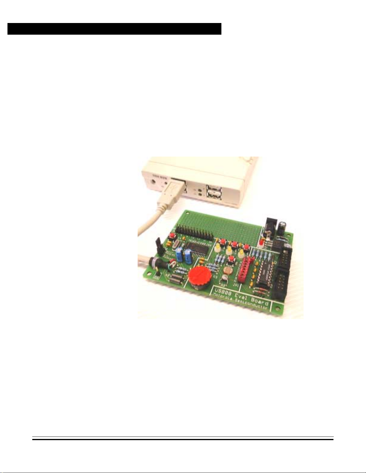
1.4 Connecting the Demo Board to the PC
Since low-speed USB devices should be equipped with a captive
connection, the USB cable is fixed on the USB08 board (downstream
direction). In the upstream direction (PC/host side), the USB
connections are always type A. Therefore, t he cable of the USB08 demo
board has a type A plug.
The connectio n of the d emo board i s made directly to the USB socket of
the PC or, as shown in the Figure 1-1, to a USB hub.
Figure 1-1. Demo Board Connected to the USB Hub
The board supply current can be delivered by the USB connection.
Therefore, the jumper JP2, which is directly beside the USB cable, has
to be in the position Bus Powered. The jumper JP1-A (jumper block,
highest position) must be opened, which corresponds to the default
shipping configuration.
Designer Reference Manual USB08 Evaluation Board
18 USB 08 Quick Start MOTOROLA
Page 19
1.5 Driver Installation
For this exam ple, the installation o f the driver softw are is described usin g
the Windows 2000 oper ating system. The installation using Windows 98
(second edition) looks quite similar.
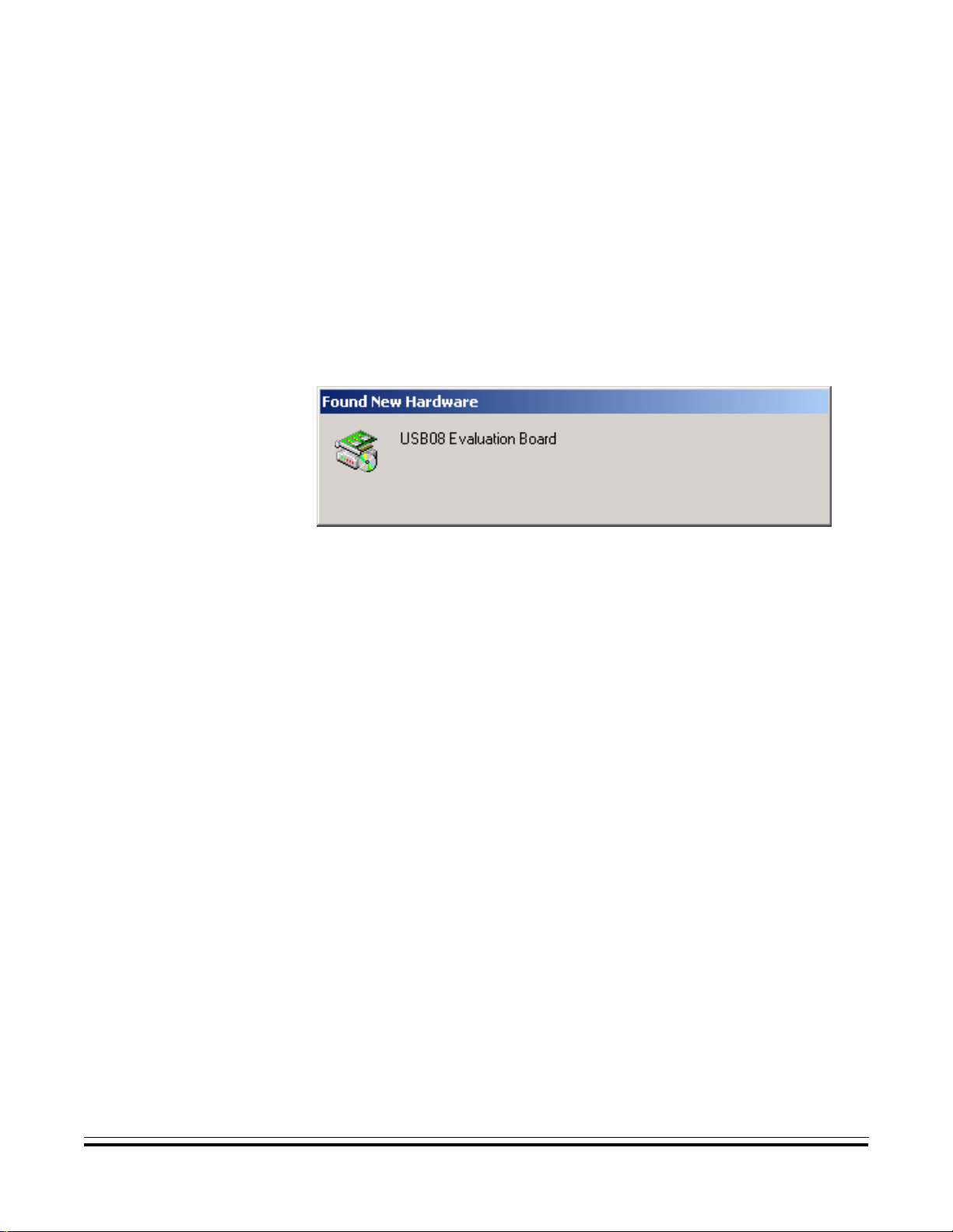
After the electrical connection of the demo board, the Windows
operating system recognizes the presence of a new hardware
component and shows the message Found N ew Hardware.
USB08 Quick Start
Driver Installation
Figure 1-2. Found New Hardware Screen
USB08 Evaluation Board Designer Ref erence Manual
MOTOROLA USB08 Quick Start 19
Page 20

USB08 Quick Start
NOTE: The installation using the Windows 2000 operating system requires
The hardware assi stan t, Fig ure 1- 3, now tr ies to find the suitable driver
information for the USB08 evaluation board. Click the Next button.
administrator rights.
Figure 1-3. Found New Hardware Wizard Start Screen
Designer Reference Manual USB08 Evaluation Board
20 USB 08 Quick Start MOTOROLA
Page 21
USB08 Quick Start
Driver Installation
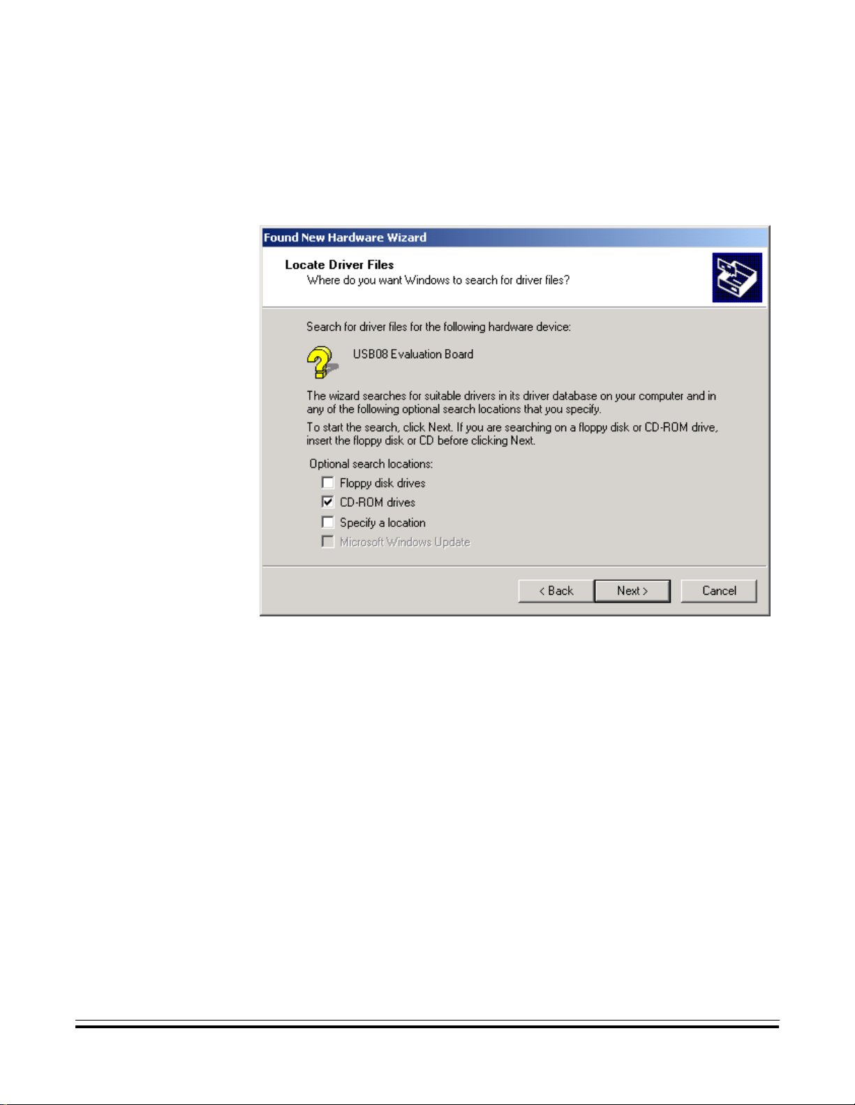
Insert the USB08 product CD into the CD-ROM drive and mark the
appropriate check box CD-ROM drives as shown in Figure 1-4. Click
the Next button.
Figure 1-4. Locate Driver Files Screen
USB08 Evaluation Board Designer Ref erence Manual
MOTOROLA USB08 Quick Start 21
Page 22
USB08 Quick Start
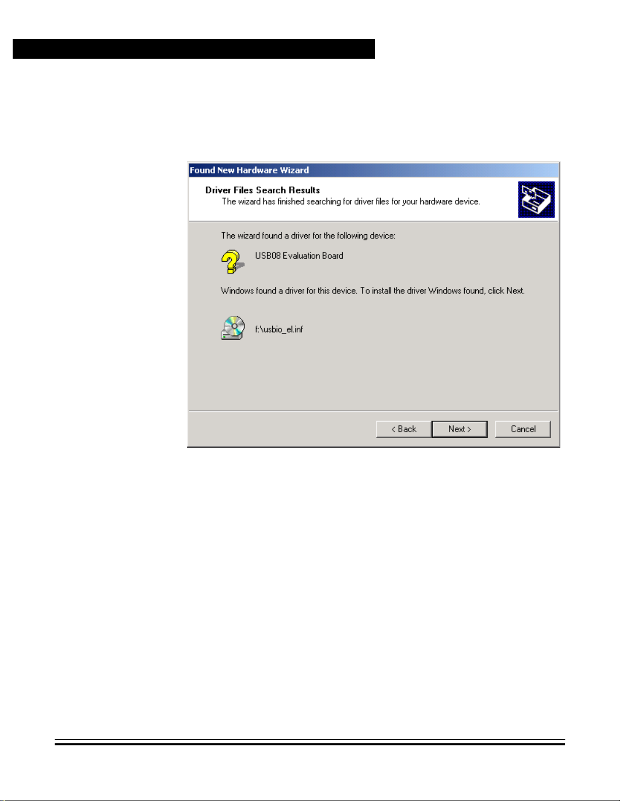
As shown in Figure 1-5, the hardware assistant will find the driver
information fil e usbio_el.inf in the root directory of the CD ROM. Confirm
this selection by clicking Next.
Figure 1-5. Driver Files Search Results Screen
Designer Reference Manual USB08 Evaluation Board
22 USB 08 Quick Start MOTOROLA
Page 23
USB08 Quick Start
Driver Installation
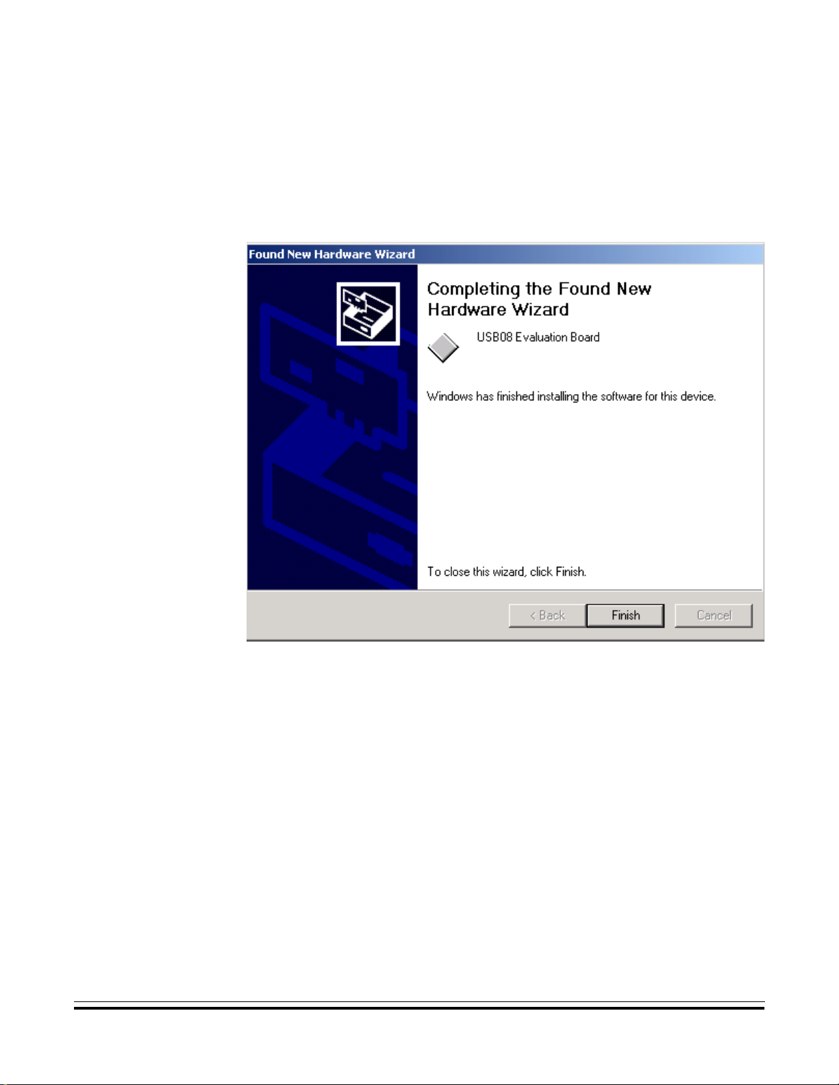
The Windows oper ating system now copies the INF file an d the driver file
usbio_el.sys to the appropriate Windows directories. After clicking
Finish (Figure 1-6), the driver installation will be completed and the
USB device will be ready for use.
Figure 1-6. Found New Hardware Wizard Finish Screen
NOTE: The installation does not require a restart of the computer, since this is
a true Plug & Play installation.
USB08 Evaluation Board Designer Ref erence Manual
MOTOROLA USB08 Quick Start 23
Page 24
USB08 Quick Start
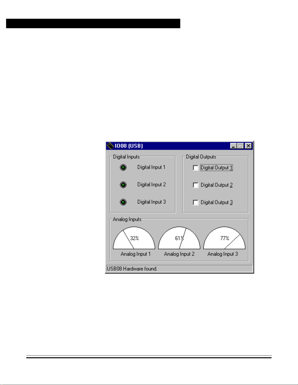
1.6 Starting the Windows Demo Application
The windows demo application:
• Shows the measur ed val u es and push butto n infor matio n com ing
from the demo board
• Allows the controlling of the demo board light-emitting diodes
(LED)
The demo application is located in the root directory of the USB08
product CD. The file name of the demo application is IO08USB.EXE.
This program can be started directly from the CD.
Figure 1-7. Windows Demo Application IO08USB
As shown in Figure 1-7, the bottom line of the applicat ion window sho ws
the status of the con nection establi shed to the US B08 demo boa rd. The
LED symbols on the left upper side of the application window can be
switched on or off by pressing the keys of the USB08 demo board.
Designer Reference Manual USB08 Evaluation Board
24 USB 08 Quick Start MOTOROLA
Page 25
USB08 Quick Start
Starting the Windows Demo Application
By setting the check boxes on the upper right side it is possible to switch
on or of f the LEDs o f the demo board. The needle pointer instruments on
the lower side of the appli cation window in dicate the measur ed values o f
the three variable resistors:
• Input 1 represents the photo sensor.
• Input 2 shows the thermistor value.
• Input 3 can be varied using the turnable regulator.
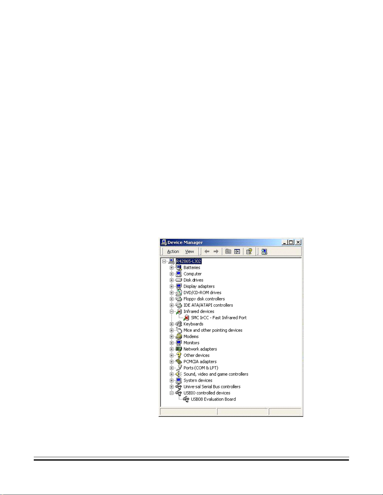
The USB08 evaluation board can be disconnected from the USB port
and reconnected at any time, because the drivers are automatically
activated or deactivated by the Windows operating system. The
activation/deactivation of the drivers can be watched in the operating
system’s device manager window (start button/settings/control panel/
system/device manager) . The catalog entry USBIO c ontrolled devices
and the device entry USB08 Evaluation Board are visible only if the
hardware is present. See Figure 1-8.
Figure 1-8. Driver Entry for USB08 in the Device Manager Window
USB08 Evaluation Board Designer Ref erence Manual
MOTOROLA USB08 Quick Start 25
Page 26

USB08 Quick Start
The Windows demo application, IO08USB.EXE, must be re-started in
the case of a hardware connection interrupt. This is because an
automatic resynchronization (though it would be possible) was not
implemented here. The demo application is arranged as simply and as
understandable as possible.
Designer Reference Manual USB08 Evaluation Board
26 USB 08 Quick Start MOTOROLA
Page 27

Designer Reference Manual — USB08 Evaluation Board
Section 2. Hardware Description
2.1 Contents
2.2 Introduction. . . . . . . . . . . . . . . . . . . . . . . . . . . . . . . . . . . . . . . .27
2.3 Technical Data . . . . . . . . . . . . . . . . . . . . . . . . . . . . . . . . . . . . .28
2.3.1 MC68HC908JB8 Microcontroller . . . . . . . . . . . . . . . . . . . . .2 8
2.3.2 USB08 Evaluation Board . . . . . . . . . . . . . . . . . . . . . . . . . . .29
2.4 Circuit Description. . . . . . . . . . . . . . . . . . . . . . . . . . . . . . . . . . .30
2.4.1 MCU Core Circuit and USB Interface. . . . . . . . . . . . . . . . . .3 1
2.4.2 Input/Output Functions. . . . . . . . . . . . . . . . . . . . . . . . . . . . .32
2.4.3 Monitor Mode Interface . . . . . . . . . . . . . . . . . . . . . . . . . . . .33
2.4.4 User RS232 Port . . . . . . . . . . . . . . . . . . . . . . . . . . . . . . . . .35
2.4.5 Power Supply. . . . . . . . . . . . . . . . . . . . . . . . . . . . . . . . . . . .36
2.2 Introduction
2.5 Board Layout . . . . . . . . . . . . . . . . . . . . . . . . . . . . . . . . . . . . . .36
2.6 Jumpers and Bridges . . . . . . . . . . . . . . . . . . . . . . . . . . . . . . . .38
2.7 Connectors. . . . . . . . . . . . . . . . . . . . . . . . . . . . . . . . . . . . . . . .40
2.7.1 Expansion Connector X 1 . . . . . . . . . . . . . . . . . . . . . . . . . . .40
2.7.2 Monitor Mode Connector X2 . . . . . . . . . . . . . . . . . . . . . . . .40
2.7.3 User RS232 Connector X3. . . . . . . . . . . . . . . . . . . . . . . . . .41
2.8 Memory Map. . . . . . . . . . . . . . . . . . . . . . . . . . . . . . . . . . . . . . .41
The USB08 evaluation board is the hardware platform for the universal
serial bus (USB ) reference desi gn. The boar d serves the provide d demo
application, which is contained in the integrated FLASH memory of the
M68HC08 microcontroller (MCU).
USB08 Evaluation Board Designer Reference Manual
MOTOROLA Hardware Description 27
Page 28

Hardware Description
Beyond that, the USB08 enables the implementation and testing of its
own M68HC08 software for evaluation purposes. For that purpose, the
board contains a monitor mode interface for reprogramming and
debugging. The monitor mode i nterface of the USB08 is compatible with
Motorola development tools such as the M68ICS08JB8 and other
third-party tools.
2.3 Technical Data
This subsection provides technical data for both the MC68HC908JB8
and the USB08 evaluation board.
2.3.1 MC68HC908JB8 Microcontroller
The main component of the USB08 evaluation board is the
MC68HC908JB8, a Motorola 8-bit MCU. Features of the
MC68HC908JB8 include:
• Efficient M68HC08 MCU core
• 8 Kbytes of on-chip FLASH memory with security feature
• 256 bytes of random-access memory (RAM)
• 3-MHz bus clock (6-MHz quartz crystal)
• 2 × 16-bit timer with:
– Input capture
– Output compare
– Pulse-width modulator (PWM)
• Low-speed USB 1.1 interface module
• Integrated 3-V voltage regulator
• Computer operating properly (COP) watchdog timer
• Low-voltage in terrupt (LVI) reset controller
• Inputs for RESET and IRQ pins
• Up to 21 input/output (I/O) lines
Designer Reference Manual USB08 Evaluation Board
28 Hardware Description MOTOROLA
Page 29

2.3.2 USB08 Evaluation Board
Features of the USB08 evaluation board include:
• M68HC908JB8 MCU packaged in a 28-pin small-outline
integrated circui t package (SOIC)
• Three light-emitting diodes (LED)
• Three input keys
• Three analog sensors:
– Light
– Temperature
– Angle of rotation
• Current supplied alternatively via USB connection or on-board
voltage regulator
Hardware Description
Technical Data
• Monitor mode interface f or in-system pr ogramming a nd debugging
• Additional RS232 interface for connection to PC or serial liquid
crystal display (LCD)
• Push buttons for reset and IRQ
• Jumper for power-on reset (POR)
• All MCU pins are accessible via a 26-pin universal expansion
connector
• Small user breadboard area reserved for customer circuit
extensions
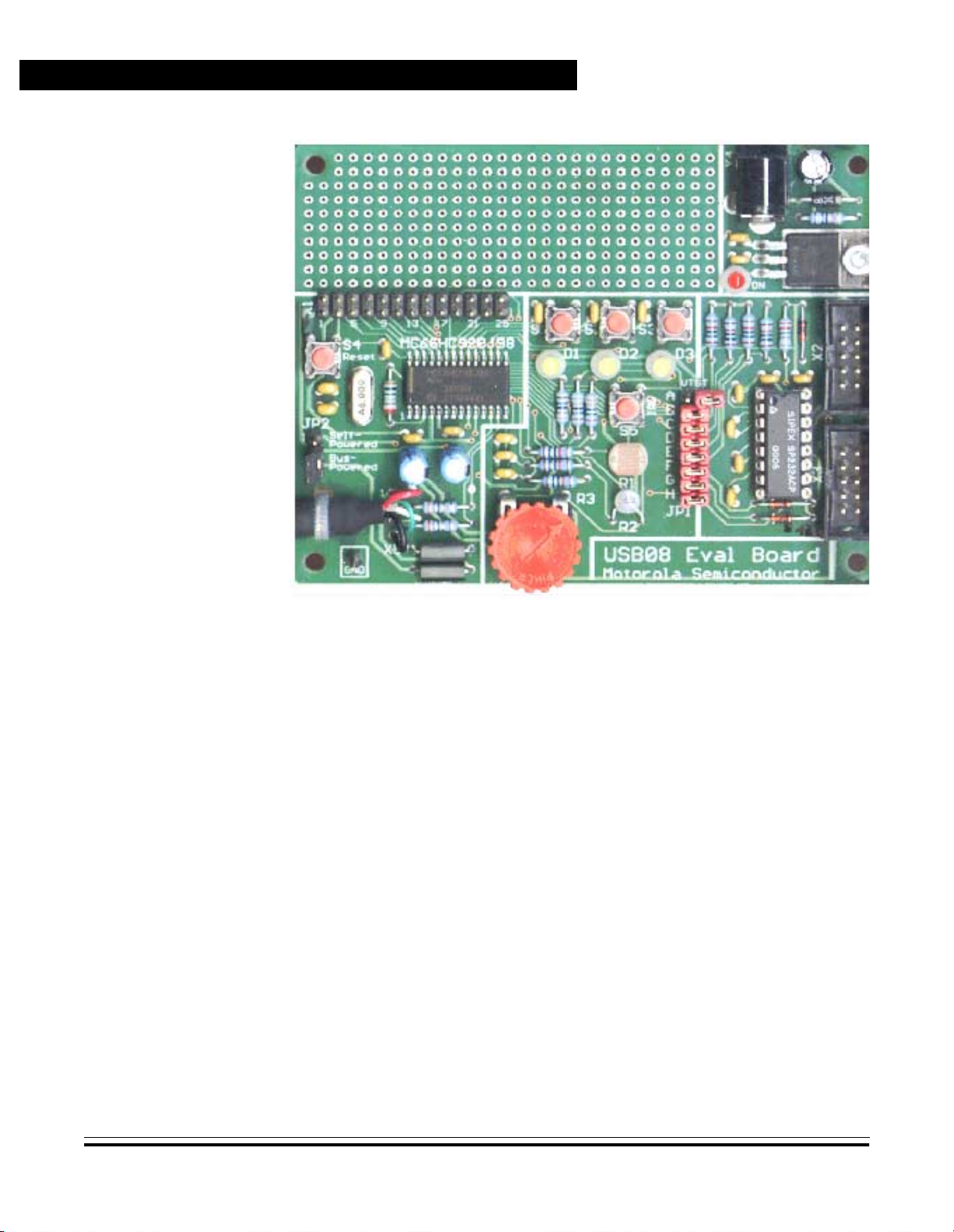
The USB08 evaluation board is shown in Figure 2-1.
USB08 Evaluation Board Designer Ref erence Manual
MOTOROLA Hardware Description 29
Page 30
Hardware Description
2.4 Circuit Description
A schematic of the USB08 de mo boa rd i s provide d in Appendix D. Bill
of Materials and Schematic. The MC68HC908JB8 MCU needs few
external elements. A wide range of peripheral functions including the
USB module and an 8-Kbyte FLASH memory are integrated on-chip.
The MC68HC908JB8 is offered in several packages. For the USB08
reference design, the 28-pin SOIC version was chosen instead of the
20-pin dual in- line packa ge (DIP) becau se the SOIC p ackage has som e
additional I/O pins.
Figure 2-1. USB08 Evaluation Board
Designer Reference Manual USB08 Evaluation Board
30 Hardware Description MOTOROLA
Page 31

2.4.1 MCU Core Circuit and USB Interface
The operating voltage, VDD, is supported by the capacitors C6 and C3
close to the MCU. Out of this primar y operating voltage of approximately
5 V, the MCU produces an internal operating voltage, V
using an integrated voltage regulator. This voltage is supported by two
capacitors, C4 and C5, and continues in the circuit as VCC.
Hardware Description
Circuit Description
, of 3.3 V,
REG
In particular, the int ernal voltage VCC/V
driver voltage supply. VCC/V
is accessible over the expansion plug
REG
connector X1. However, it must be noted that VCC/V
is used as the USB inter face
REG
can be
REG
additionally loaded only with a few milliamps.
For clock generation, the external elements Q1, C1, C2, and R18 are
used. These elements form a Pierce oscillator together with the active
elements integrated in the MCU. This oscillator produces a clock
frequency of 6 MHz. Th e inter nal bus clock of the MCU (3 MHz) as well
as the USB clock (1.5 MHz) are derived from the main clock frequency.
The USB data lines are conn ected to the MCU pins PTE 3 (USB D+) and
PTE4 (USB D–). So that the USB hub will be able to classify this
equipment as a low-speed USB device, a pullup resistance of 1.5 kΩ
(R7) to the data line D– is required.
On the demo board, R7 is not installed. This is because the
MC67HC908JB8 ha s an additional inter nal pullup at PTE4 wh ich can be
activated and de-activated by software.
To optimize the connection adjustment, the serial resistors in the data
lines R16 and R17 and inductances (fer rite beads) in the current supply
path L1 and L2 are used. However, these measures are optional.
The reset system of the M68HC08 shows clear differences from other
Motorola M CUs ( M68HC11 an d M68H C12 ). For e xampl e, the ca pacitor
C19 at the reset pin of this circuit could never be used in an M68HC11
system. This is because the MC68HC908JB8 has an integrated
low-voltage i nh ibit ( LV I) circui t. T her efore , n o exter nal reset con t roller is
required.
USB08 Evaluation Board Designer Ref erence Manual
MOTOROLA Hardware Description 31
Page 32

Hardware Description
2.4.2 Input/Output Functions
For demonstration purposes, the board has:
• Three push buttons
• Three light-emitting diodes (LED)
• Sensor resistors
The push butto ns are c onnecte d to the three por t pins PTA4, PT A5, and
PTA6. By pushing the buttons, a low level is produced on the appropriate
input. Since the port pins have internal pullup resistors, no external
resistors are required. The buttons are bridged with capacitors, to
support corr ect reading of the inputs by the software and to avoid n oise.
The occurrence of the high-l ow edge at the respective pin of port A is an
input event which results in the generation of a keyboard interrup t by the
MC68HC08JB8. This interrupt is then used by the program (see
Section 3. Software Module Descriptions).
For optical si gnalling, three LEDs are att ached to p ort D. These p ort pins
have a high drive capabilit y of up to 25 mA. Therefore, it is not necessary
to use a driver . On the boa rd, PTD 0, PTD1, and P TD2 are used for LE D
control. All outputs generated by the port D pi ns have an open-drain
characteristic and are 5-V tolerant.
The remaining port D pins (PTD3–PTD6) are used for controlling the
software analog- to-digital converter (ADC). The A DC i mplem enta tion i s
described in detail in Section 3. Softwa re Module Descriptions as well
as in the application note entitled Simple A/D for MCUs without Built-in
A/D Converters, Motorola document order number AN477/D. This
application note can be found on the World Wide Web at:
http://www.motorola.com/semiconductors/
The software ADC senses the resistance of:
• R1 (photo resistor)
• R2 (thermistor)
• R3 (potentiometer)
To determine capa cit or load ti mes , th e M CU pins P TE0–PTE2 serve as
trigger inputs for the software ADC.
Designer Reference Manual USB08 Evaluation Board
32 Hardware Description MOTOROLA
Page 33

The I/O pins of the MCU ar e accessibl e on the expansion con nector X1.
User specific peripheral circuits can be attached to X1.
NOTE: It may be that not all functions of the demo board may be used with
user-specific peripheral circuits attached to X1.
2.4.3 Monitor Mode Interface
For FLASH pr ogramming and software de bugging, the MC68HC 908JB8
uses a special operating mode, monitor mode. The difference between
monitor mo de and normal user mode is that fi rmware out of th e read-only
memory (ROM) is executed instead of the user program. First, this
firmware exam ines a set of I/ O pins and specif ies the concre te operating
parameters. Finally, this firmware establishes an asynchronous serial
interface function on the port pin PTA0. This interface works
bidirectionally (half duplex) and corresponds to the usual RS232
conventions. The baud rate equals 9600 baud. An additional
requirement, besides the quartz clock (6 MHz), is the allocation of
certain logic levels to some port pins as listed in Table 2-1.
Hardware Description
Circuit Description
Table 2-1. Port A Monitor Mode Entry Levels
Port Pin Level
PTA0 High
PTA1 High
PTA2 Low
PTA3 High
The monitor mode ci rcuitr y on th e evalu ati on bo ard prod uces the levels
shown in Table 2-1 using four pullup or pulldown resistors. These
resistors are connected to the MCU using the jumper s JP1-C–JP1-F.
After removing these jumpers, a previously loaded user program can
access the four po rt A pins without restrictions.
Apart from the above requirements, to enter monitor mode it is
necessary to apply a voltage of approximately 7–10 V to the IRQ
pin of
the MCU. This voltage is generated by the RS232 transceiver’s (IC2)
charge pump and l imited to 8.2 V using the breakdow n diode D7. JP 1-A
USB08 Evaluation Board Designer Ref erence Manual
MOTOROLA Hardware Description 33
Page 34

Hardware Description
is the first ju mper of the j umpe r block JP1, and it m ust be set in o rder to
apply high voltage to IRQ.
If the monitor mode interface is not needed or if it disturbs the
investigation of certain circuit configurations, it can be uncoupled
completely from the MCU core. For this purpose:
Using the X2 plug connector, the monit or mode interface is connected to
the PC. The monitor mode cable consists of:
A one-to-one connectio n is imp lement ed by this cabl e configu ration , as
shown in Table 2-2.
• All jumpers of jumper block JP1 have to be removed.
• RS232 receiver IC2 has to be removed from the socket.
• A flat cable with a Berg connect or (2 × 5 pin, crimping connection)
on the device side
• A sub-D9 connector (crimping connection) on the PC side
Table 2-2. Monitor Mode Cable Pin Configuration
X2 Pin USB08 Monitor PC RS232 Sub-D 9 Pi n
3 T1OUT RxD 2
5 R1IN TxD 3
9 GND GND 5
The MC68HC908JB8 logic levels are based on the operating voltage
(3.3 V); however, the transceiver IC2 works with VDD (5 V). The
V
CC
adjustment of the logic levels according to specification is not difficult
(refer to the individual integrated circuit data sheets). The Schottky
diode, D6, enables the push/pull exit R1OUT to be wired-OR capable
and prevents a feeding of levels beyond the tolerance limit of the input
PTA0.
Designer Reference Manual USB08 Evaluation Board
34 Hardware Description MOTOROLA
Page 35

2.4.4 User RS232 Port
NOTE: The MC68HC908JB8 does not have a serial communications interface
Hardware Description
Circuit Description
The monitor mode interf ace uses only one sending/recei ving chann el of
the RS232 transceiver IC2. The remaining channel is used for an
additional user RS232 port.
In contrast to th e RS232 channel for the monitor mode interface, the user
RS232 port incorporates separate sending and receiving lines. The
PTA7 pin of th e MCU i s u sed for re cei ving an d the PT C0 pin i s used fo r
sending.
(SCI) hardware module for asynchronous serial commun icati on.
Therefore, the necessary timing has to be generated by software.
If PTA7 and/or PTC0 are to be used, the diode D5 serves for the
adjustment of the logic levels between 5 V and 3 V. Otherwise, the
RS232 transceiver can be uncoupled from the MCU by removing the
jumpers JP1-G and JP1-H.
X3 is the u ser RS23 2 por t plu g con nector . If this inte rface is atta ched to
a PC, a line connection similar to the monitor mode interface is
necessary. In this case, the bridges BR1 and BR2 on the downside of
the printed circui t board (PCB) (se e Figure 2-3) have to be connected in
positions 1 and 2. For this configur ation, the PC works a s a host a nd the
USB08 board represents the device side.
The reverse case happe ns, if a serial liquid crystal display (LCD) is to be
operated at the user RS 232 por t. In this conf igurat ion, the U SB08 boar d
is the host and the LCD module represents the device side. The
necessary RxD/TxD crossing is done by configuration of the bridges
BR1 and BR2 in positions 2 and 3 . At the sam e time, the ser ial LCD can
be supplied with operating voltage by closing the bridge BR3.
NOTE: This specification deviates from standard RS232 mapping.
Serial alphanumeric LCDs are offered by several vendors. In the test
configuration, the LCDs used are from the Canadian manufacturer
Matrix Orbital (http://www.matrixorbital.com).
USB08 Evaluation Board Designer Ref erence Manual
MOTOROLA Hardware Description 35
Page 36

Hardware Description
2.4.5 Power Supply
Power can be sup pli ed to the USB08 b oard by using the USB or via the
voltage regulator IC3. The change between these options is done by
replacing the jumper JP2. If the jumper is placed in position 2–3 (Bus
Powered), the operating power is supplied by V
USB.
If a dc voltage between 8 V and 20 V is fed into the power plug X4 in
jumper position 1–2 (Self Powered), the voltage regul ator IC3 suppli es
5 V in the case. The solder bridge BR4 on the downside of the PC B (see
Figure 2-3) has to be in position 1–2. Alternatively, if the bridge BR4 is
in position 2–3, a stabilized 5-V power supply can be used to feed V
directly.
The voltage regulator IC3 is specified with 1 ampere. Although no
special cooling measures are intended, IC3 is more than sufficiently
dimensioned. The input current of the board, even in the worst case, is
clearly smaller than 100 mA.
Bus
and V
GND
from the
DD
2.5 Board Layout
A USB hub sup plies a t leas t 100 mA. Therefo re, the power su pply of the
board via the USB is possible without any problem. The USB08 board
power input specification shou ld be reg istered in the device descript or of
the USB device (see Section 4. U niversal Serial B us (USB) In terface).
Figure 2-2 and Figure 2-3 show the components and parts layout, as
well as a general picture of the board.
On the component side, Figure 2-2:
• The jumpers, plugs, push buttons, and LEDs are marked.
• The USB cable is fixed on the board with a cable strap, and the
four line ends are soldered directly to the X5 connection points
(without patch cord). This kind of connection is usual for
low-speed USB devices.
A detailed layout plan of the USB08 board with the names of all
components is shown in Figure 2-3.
Designer Reference Manual USB08 Evaluation Board
36 Hardware Description MOTOROLA
Page 37

Hardware Description
Board Layout
Figure 2-2. PCB Component Side Layout Plan
Figure 2-3. Detailed Layout Plan
USB08 Evaluation Board Designer Ref erence Manual
MOTOROLA Hardware Description 37
Page 38

Hardware Description
2.6 Jumpers and Bridges
The jumper configuration is shown in Table 2-3.
Table 2-3. Jumper Configuration
Jumper
JP1-A
JP1-B
JP1-C
JP1-D
JP1-E
JP1-F
JP1-G
Position
Closed High voltage on IRQ to enter monitor mode
Closed* RS232 is connected to the power supply.
Closed* PTA0 is used for monitor mode communication.
Closed* PTA1 is used for monitor mode configuration.
Closed* PTA2 is used for monitor mode configuration.
Closed* PTA3 is used for monitor mode configuration.
Closed* PTA7 serves as receiving line for the user RS232.
(a)
Open* Norm al user mode
Open RS232 is disconnected from the power supply.
Open PTA0 can be used without restriction.
Open PTA1 can be used without restriction.
Open PTA2 can be used without restriction.
Open PTA3 can be used without restriction.
Open PTA7 can be used without restriction.
Function
Open PTC0 can be used without restriction.
JP1-H
Closed* PTC0 serves as transmission line for the user RS232.
1-2 Self-powered: power supply via voltage regulator
JP2
a. * = delivery status
2-3* Bus-powered: power supply via USB
Placement of the solder bridg es on the downside of the PCB is shown in
Figure 2-4. Table 2-4 shows the solder bridges configuration.
Designer Reference Manual USB08 Evaluation Board
38 Hardware Description MOTOROLA
Page 39

Hardware Description
Jumpers and Bridges
Table 2-4. Solder Bridges Configuration
Solder
Bridge
BR1
and BR2
BR3
BR4
1. * = delivery status
Position
1-2* User RS232 configured in external device mode (PC)
2-3 User RS232 configured in host mode (LCD connection)
Open*
Closed
1-2* Power su pply via voltage regulator, 8–20 V needed at X4
2-3 Power su pply directly from X4, must be stabilized at 5 V
Figure 2-4. Solder Bridge Placement
on Downside of the PCB
(1)
V
is not present at user RS232 port (standard).
CC
VCC is present at pin 9 of the user RS232.
Function
USB08 Evaluation Board Designer Ref erence Manual
MOTOROLA Hardware Description 39
Page 40

Hardware Description
2.7 Connectors
The connectors are described here.
2.7.1 Expansion Connector X1
V
RTS 3 4 PTA0
PTD0
PTD1
PTD2
PTD3
PTD4 13 14 PTA5
PTD5
PTD6
PTE3 19 20 PTE0
PTE4
PTC0
GND 25 26 GND
1 2 V
DD
5 6 PTA1
7 8 PTA2
9 10 PTA3
11 12 PTA4
15 16 PTA6
17 18 PTA7
21 22 PTE1
23 24 PTE2
CC
X1
2.7.2 Monitor Mode Connector X2
N.C. 1 2 N.C.
PC_RxD
PC_TxD
N.C.
GND
3 4 N.C.
5 6 N.C.
7 8 N.C.
9 10 N.C.
X2
Designer Reference Manual USB08 Evaluation Board
40 Hardware Description MOTOROLA
Page 41

2.7.3 User RS232 Connector X3
N.C. 1 2 N.C.
Hardware Description
Memory Map
2.8 Memory Map
Rx (Tx)
Tx (Rx)
N.C.
GND 9 10 N.C.
3 4 N.C.
5 6 N.C.
7 8 V
DD
X3
Table 2-5. MC68HC908JB8 Memory Map
From To Size Content
0x0000 0x003F 64 bytes Control registers
0x0040 0x013F 256 bytes RAM
0x0140 0xDBFF — Reserved
0xDC00 0xFBF F 8 Kbytes FLASH memory
0xFC00 0xFFDF — Reserved
0xFFE0 0xFFFF 32 bytes Interrupt vector table (FLASH)
For a detailed description of the MC68HC908JB8 memory map, in
particular the addresses of control registers and interrupt vectors, refer
to the MC68HC908JB8 Technical Data, Motorola document order
number MC68HC 908JB8/D.
USB08 Evaluation Board Designer Ref erence Manual
MOTOROLA Hardware Description 41
Page 42

Hardware Description
Designer Reference Manual USB08 Evaluation Board
42 Hardware Description MOTOROLA
Page 43

Designer Reference Manual — USB08 Evaluation Board
Section 3. Software Module Descriptions
3.1 Contents
3.2 Introduction. . . . . . . . . . . . . . . . . . . . . . . . . . . . . . . . . . . . . . . .43
3.3 General Structure of the M68HC08 Firmware . . . . . . . . . . . . .44
3.4 How to Build the Compiler Project . . . . . . . . . . . . . . . . . . . . . .45
3.5 Main Module U08MAIN.C. . . . . . . . . . . . . . . . . . . . . . . . . . . . .48
3.6 Interrupt and Reset Vector Module VECJB8.C. . . . . . . . . . . . .49
3.7 C Startup Module CRTSJB8.S . . . . . . . . . . . . . . . . . . . . . . . . .50
3.8 Push Button Module U08KEY.C. . . . . . . . . . . . . . . . . . . . . . . .50
3.2 Introduction
3.9 LED Control with U08LED.H. . . . . . . . . . . . . . . . . . . . . . . . . . .52
3.10 Software ADC Module U08ADC.C . . . . . . . . . . . . . . . . . . . . . .52
3.11 RS232 Communication Module U08232.C. . . . . . . . . . . . . . . .54
3.12 USB Communication Module U08USB.C. . . . . . . . . . . . . . . . .56
3.13 Compiler Specific Adjustments. . . . . . . . . . . . . . . . . . . . . . . . .57
This section describes the structure and interaction of the software
modules. These software modules, running on the Motorola
microcontroller MC68HC908JB8, form the firmware of the USB08
reference design.
USB08 Evaluation Board Designer Reference Manual
MOTOROLA Software Module Descriptions 43
Page 44

Software Module Descriptions
3.3 General Structure of the M68HC08 Firmware
The firmware of th e M68H C08 consists of sever al source cod e modules
which are embedded into a common compiler project. The main()
function is contai ned in the module U08MAIN.C. It controls the progr am
sequence via an endless loop (as usual in embedded software). The
module U08KEY.C settles the scanning of the input keys. Control of the
light-emit ting diodes (LED) on th e board is done usin g simpl e C m acros;
no special C module is required for this purpose. The module
U08ADC.C is responsible for reading of the resistive sensors.
These modules are supported by the file VECJB8.C, whi ch contains the
interrupt and reset vectors. The four C source code modules are merged
into a common compiler project. In addition, the assembler module
CRTSJB8.S which contains the C startup code is required.
The control of keys, LEDs, and analog-to-digital (A/D) transmitters are
support functions to the demonstration project because the main
attention is paid to the communication interface. The communication
functions are implemented directly b y means of “#include” in structions in
the main module U08MAIN.C.
Two ways of communication are implemented in the demonstration:
RS232 or USB. The selection takes place by defining USE_USB_ PIPE
in the head of the main module. If this macro is defined, U08USB.C
automaticall y becomes a part o f the main module ; otherwise, the RS232
communication module U08232.C is merged.
If the USB implementation in the file U08USB.C is used, the file
U08DESC.C is also translated at the same time. It contains the static
data for all necessary USB descriptors.
For each of the C files U08KEY.C, U08ADC.C, U08USB.C, and
U08232.C there is a correspondi ng header file (* H) with the sam e base
name. The functions for controlling the LEDs o n the board are contain ed
as macros in the file U08LED.H. In several cases, the header
MC68HC08JB8.H conta ins the register and bit mask defin itions required
by the MC68HC908JB8 microcontroller (MCU).
Designer Reference Manual USB08 Evaluation Board
44 Software Module Descriptions MOTOROLA
Page 45

Figure 3-1 shows the structure and interacti on of the mod ules and files
that could be included by means of “#include” instructions. To
accomplish a complete compiler build, the grey modules have to be
included in a compi ler project.
3.4 How to Build the Compiler Project
The Cosmic C Compi ler can to arrange a pro ject within the compiler IDE.
The compiler project owns:
• A list of source modules to be complied
• Translation options
• Additional tools such as S-record generation
Software Module Descriptions
How to Build the Compiler Project
HC08JB8.H
Regis ter D ef ini tions
U08USB.H
USB Communication
U08232.H
RS23 2 Com m unicati on
U08KEY.H
Push Button Module
U08LED.H
LED Functions
U08ADC.H
Soft ADC Module
Figure 3-1. Structure and Dependencies of the Firmware Files
Project Files
CRTSJB8.S
C-Star tu p Mo dule
U08MAIN.C
Main Mod ule
U08KEY.C
Push Button Module
U08ADC.C
Soft ADC Module
VECJB8.C
Interrupt Vectors
U08DESC.C
USB Descriptors
U08USB.C*)
USB Communication
U08232.C*)
RS232 Com m un ic ation
*) = Alternative
USB08 Evaluation Board Designer Ref erence Manual
MOTOROLA Software Module Descriptions 45
Page 46

Software Module Descriptions
The compiler project for the USB08 reference design covers these C
modules (see Figure 3-1 ):
• U08MAIN.C
• U08KEY.C
• U08ADC.C
• VECJB8.C
An alternative possibility consists of controlling the translation of the
project via a batch file as shown in this example (BUILD.BAT).
cx6808 -v -l u0 8m ain.c u08adc.c u08key.c vecj b8 .c
clnk -o usb08.h08 usb08.lkf
chex -fm -h -o usb08.s19 usb08.h08
This batch file can be invok ed under the MS- DOS® system environment
to translate and link USB08 firmware components. The result of this
process is a S-recor d file nam ed USB08.S19, which can be loaded into
the FLASH memory of the MC68HC908JB8.
Another important file for controlling the translation is the linker file
USB08.LKF:
# USB08 LIN K CO MM AND FILE
# COSMIC HC08 C COMPILER
#
+seg .te xt -b 0xd c00 -n .text # program start add re ss
+seg .co nst -a .t ext # constants follow code
+seg .bsct -b 0x0040 -n .bsct # zero page start address
+seg .ubsct -a .bsct -n .ubsct # data start address
+seg .da ta -a .ub sct # data start address
+def __sbss=@.bss # start address of bss
# Put your st ar tu p file here
crtsjb8.o # startup routine
# Put your fi le s he re
u08main.o
u08key.o
u08adc.o
# "c:\pr ogr am s\cosmic\cx08\Lib\l ib i. h0 8"
"c:\programs\cosmic\cx08\Lib\libm.h08"
+seg .const -b 0xfff0 # vectors start address
# Put your in te rr upt vectors file here if neede d
vecjb8.o
+def __memory=@.bss # symbol used by library
+def __stack=0x013f # stack pointer initial value
MS-DOS is a registere d trademark of Microsoft Corporation in the Unit ed States and/or other
countries.
Designer Reference Manual USB08 Evaluation Board
46 Software Module Descriptions MOTOROLA
Page 47

Software Module Descriptions
How to Build the Compiler Project
In the linker file:
• The starting addresses of the various segments are set.
• The text segment starts at the address 0xDC00 (for example, at
the beginning of the internal FLASH memory).
• The constants immediately follow the text segment.
• The zero page starts at 0x0040 instead of the usual 0x0000.
• The MC68HC908JB 8 cont rol reg i sters ar e locate d in the add ress
range 0x0000–0x0040.
• The data segment follows the zero page in the random-access
memory (RAM).
• The interrupt vectors start at 0xFFF0 and the stack pointer is set
to 0x013F (end of the internal RAM memory).
Table 3-1 shows the approximate values for memory utilization when
USB communication has been implemented.
Table 3-1. Memory Utilization
Starting
Address
0x0000 0x003F 64 byte MC68HC908JB8 control registers
0x0040 0x0075 53 byte Variables in RAM
0x0076 0x0117 163 byte Free RAM
0x0118 0x013F 40 byte Stack in RAM
0xDC00 0xE2FF 1.8 Kbyte Code and constant values
0xE300 0xFBFF 6.2 Kbyte Fr ee FLASH memory
0xFFF0 0xFFFF 16 byte Interrupt and reset vectors
End
Address
Length Contents
USB08 Evaluation Board Designer Ref erence Manual
MOTOROLA Software Module Descriptions 47
Page 48

Software Module Descriptions
3.5 Main Module U08MAIN.C
Which variant to be compiled is specified at the head of this module
using the macro USE_USB_PIPE. If defined, the USB version will be
produced; otherwise, the RS232 version will be produced.
The two versions are formed by merging different “#include” files. In
addition, the n ames of th e i nter face function s used in th e ma in pr ogra m
are standardized. For example:
• If the RS232 version is active, the getSSCI() (for receiving a
character via RS232) is renamed by a macro to getPipe().
• If the USB version i s active, getPipe() is mapped to getUSB().
This enables the use of uniform function names in the main program,
independent of the version selected in each case.
The function main() contai ns the contin uous loop o f the master program.
As usual, it is called by the C startup module after all fundamental
hardware and system initializations are finished. Also, at the beginning
of these initializations, the C startup module calls the function
_HC08Setup(). In this function, all register accesses and initializations,
which must take place immediately after system resets, are
summarized. The summarizing of these initializations within its own
function keeps the C sta rtup mod ule stati c. It has the adva ntage tha t the
C startup mod ule does no t have to b e changed and retr anslated, even if
further initialization steps become necessary.
At the beginning of function main() the peripheral modules used by the
program are initialized:
• initPipe() — communication module (RS232 or USB)
• initLED() — LED readouts
• initKey() — keyboard entry
• initSADC() — software analog-to-digital converter (ADC)
Subsequently, the I flag is deleted to enable global interrupts.
Designer Reference Manual USB08 Evaluation Board
48 Software Module Descriptions MOTOROLA
Page 49

Software Module Descriptions
Interrupt and Reset Vector Module VECJB8.C
The main program loop uses this operational sequence:
1. An analog-to-digital (A/D) conversion is performed. One of three
conversion channels is updated in each cycle run. This procedure
was selected because the transformation, with the simple ADC
software implemented in the module U08ADC.C, takes several
milliseconds.
2. Subsequently, the delivery of a n 8-byte data telegram by t he i nput
pipe is accomplished. This length was chosen because it
corresponds to the number of bytes sent by the PC program.
The necessary information for the control of the three LEDs is
contained in the first three bytes. If the received byte is 0, the
respective LED is switched off; otherwise, it is switched on.
3. To send an answer telegram back at the host PC, first fill the send
buffer utilizing the first six bytes of the eight byt es available. In the
first three bytes, the status of the input keys is coded. The next
three bytes transmit the last values of the three analog converter
channels.
4. Now the function putPipe() is called eight times to send the data
telegram. Afterward, the entire cycle run is repeated.
All further program functions, in particular the communication via USB
and the processing of the push button events, are processed by i nterrupt
functions.
3.6 Interrupt and Reset Vector Module VECJB8.C
The file VECJB8.C contains the definitions of the interrupt vector table
placed at the end of the M68HC 08 memory map. The entries in thi s table
are the start addresses of the respective interrupt service routines. The
MC68HC908JB8 uses eight (7 + 1) vectors. The last, highest position
(address 0xFFFE/0xFFFF) is used by the reset vector.
In the USB08 refere nce design, the key pad interrupts of the input/output
(I/O) port A are used as well as the USB interrupts in case the USB
implementation was activated. The other interrupt vectors refer to an
empty dummy interrupt service routine (ISR). This dummy ISR is
USB08 Evaluation Board Designer Ref erence Manual
MOTOROLA Software Module Descriptions 49
Page 50

Software Module Descriptions
practically without function; however, it can be used in the debugging
phase for seeking out unexpected (spur ious) inter rupt s. In additio n, the
allocation of all interrupt vectors is important for the implementation of
the FLASH memory security feat ure (read-out protection). For additional
information, refer to the MC68HC908JB8 Technical Data, Motorola
document order number MC68HC908JB8/D.
The reset vector refers to the start add ress of the applica tion. This point
of entrance is located in the C startup module.
3.7 C Startup Module CRTSJB8.S
The C startup module used essentially corresponds to the standard
startup module from the Cosmic C Compiler package with one
exception. Immediately after a reset (and after the initialization of the
stack pointer), a subroutine reference was inserted to _HC08Setup().
This subfunction is defined in U08MAIN.C and performs urgent
accesses to M68HC08 control registers which should be completed
immediately after the reset.
3.8 Push Button Module U08KEY.C
Port A (PTA) of the MC68HC908JB8 has eight port bits for keyboard
connection. Each of these lines can cause an interrupt. The port bits
individually can be configured for use within the MC68HC908JB8
keyboard interrupt module (KBI).
The USB08 evaluation board uses three single keys which are
connected to port lines PTA[4:6]. The switch noise reduction is
performed via a resistor-capacitor (RC) combination at each key. This
combination is made by:
• M68HC08 intern al pu llup r esistors and a capacitor (parallel to th e
key)
• Hysteresis of the port A input Schmitt triggers
Designer Reference Manual USB08 Evaluation Board
50 Software Module Descriptions MOTOROLA
Page 51

Software Module Descriptions
Push Button Module U08KEY.C
The KBI module of the MC68HC 9 08JB8 great ly simplif ies the scanning
of the attached buttons. The software necessary for this takes only 20
lines of C code.
The conditions a re created in the initialization f unction initKey(). First the
internal pullup resistors at the port A pins are activated. A short puls e of
an active H level is driven at the por t A pins which accel erates the rising
of the logic levels at these pins. This prevents a false read ing of the initial
low level on the lines.
The initialization function ends with the resetting of the status variable,
KeyState, and the enabling of the keyboard interrupt.
During the man ipulation of a key, the interrupt service routine is rKey() is
called. At port A, the pressed key is seen as a 0 bit. The appropriate bit
location is set accordingly in the status varia ble KeyState. B y activation
of a key the key status is inverted. This implementation simulates an
on/off push button.
If the main p rogram w a nts to know th e cur rent status of a k ey (o n/off) , it
uses the access function getKey(). The number of the key (1...) will be
handed over as a function a rgument. The function getKey() calc ulates a
bit mask for access to an individual bit of the (internal) status variable
KeyState. The return value amo unts to 0, if the key is off; otherwise, a 1
is returned.
This module provides an easy way to specify the desired number of
possible keys. For this purpose, two macros are used. KEY_MASK
defines the used lines of por t A by setting a “one” flag at the ap propri ate
bit location. The macr o KEY_FIRST defines a t which bit location the first
key is attached. Some examples:
KEY_MA SK =0x 01; KE Y_FIRST=0; / / one key at PT A[ 0 ]
KEY_MA SK =0x 02; KE Y_FIRST=1; / / onea key at PTA [1 ]
KEY_MA SK =0x 80; KE Y_FIRST=7; / / one key at PT A[ 7 ]
KEY_MA SK =0x 70; KE Y_FIRST=4; / / three key s at PTA [4 ..6 ]
KEY_MA SK =0x F0; KE Y_FIRST=4; / / four keys at PT A[ 4. .7 ]
KEY_MA SK =0x FF; KE Y_FIRST=0; / / eight key s at PTA [0 ..7 ]
The port bits included in the key scan have to follow one after another.
USB08 Evaluation Board Designer Ref erence Manual
MOTOROLA Software Module Descriptions 51
Page 52

Software Module Descriptions
NOTE: It has to be p ointed out for completeness, that with the KBI mod ule of the
MC68HC908JB8 not only single keys but also extensive key fields in
matrix arrangement can be easily scanned.
3.9 LED Control with U08LED.H
Controlling the three light-emitting diodes (LED) attached to port D is
easy. For initial ization, the dat a direct ion of the used po rt pins PTD[0 ..2]
has to be switched to an output state. The initialization as well as the
switching of th e LEDs is perform ed via four macro s. Therefore, a header
file is enough for the realization of these functions. A special C modul e
is not required in this case.
The LEDs are addressed, beginning with a 1. The switching on of the
first LED (at PTD[0]) takes place, for example, by means of:
onLED(1);
3.10 Software ADC Module U08ADC.C
Although the MC68HC908JB8 does not have an integrated ADC, it is
nevertheless possible to measure analog values (and in particular
resistance values) in a simple w ay. For this p urpose, an RC com bination
is attached to a conventional digital port pin and the load time of the
capacitor is measured. The working principle is shown in Figure 3-2.
GND
V
CC
R
E
C
S
Figure 3-2. Measurement of Resistor Values Using a Digital Input
Designer Reference Manual USB08 Evaluation Board
52 Software Module Descriptions MOTOROLA
Page 53

Software Module Descriptions
Software ADC Module U08ADC.C
First, the switch S is closed and the capacitor C uncharged. As soo n as
the switch S is opened, the charging procedure begins. The voltage at
the input E of the microcontroller rises according to the exponential
function:
UE(t) = VCC (1 – e
(–t/RC)
)
The threshold voltage at the input pin of the MC68HC908JB8, from
which a level change from low to high takes place, is approximately
50 percent of the operating voltag e VCC. Until this th resho ld is reached,
the loading time, tx, amounts to:
= K * RxC with K~0,7 for VCC/2
t
x
Since k represents a co nstant value (in the con sidered short time frame ),
a linear connection between the measured time and the product RxC
appears. Since C i s constan t, one can draw a di rect conclu sion from th e
charge time to the value of the resistance Rx.
To determine the absolute resistance o f Rx, first the value of the capacity
C and the constant k have to be determined. However, that is not
economical (particu larly with series products having a certain distr ibution
of its value). Instead, one can accomplish a calibration cycle before the
actual measuremen t. T his calibration cycle use s a refer ence resistan ce
value R0 and determines the time t0. Th e following measure cycle uses
series connection Rx, cons isting of the reference resistance R0 and the
variable resistance R1 (for example, RX = R0 + R1), to determine the
time tx. The result can be calculated using the relationship:
R1/R0 = (Rx–R0)/R0 = (tx–t0)/t
0
The range of values of the result is between 0 and 1, if R1max = R0.
The software ADC module of the USB08 application serves three A/D
channels (see Section 2. Hardware Description). Reaching the
threshold voltage is sensed via the port pins PTE[0..2]. The switch
function for charging/discharging the capacitor is realized by switching
the port pins as outputs. In contrast to the circuit diagram (Figur e 3-1),
the polarity is exchanged (for instance, the point of reference is VCC
instead of groun d) and the charge of the capacitor is ma de by activa ting
USB08 Evaluation Board Designer Ref erence Manual
MOTOROLA Software Module Descriptions 53
Page 54

Software Module Descriptions
the ground po tential at the resistors via the port pins PTD[3..5]
(calibration cycle) and PTD[6] (measuring cycle).
Before the software of the ADC module can be used, the initialization
function initSADC() has to be called. In addition, the main timer is
required to run with 3 MHz (prescal er 0). The clockin g of three impulses
per microsecond is the basis of the time measurement in this module.
The function respon sible for the A/D conversion of one channel at a tim e
is getSADC(). The channel number (1..3) is handled as a parameter.
The A/D conversion is performe d in the two menti oned steps: calibra tion
and measurement.
The desired 8- bit range for the results (values of 0…255) is a result of
scaling of the A/D output. In order to keep the run time of the necessary
division and multiplication operations small, the scaling function is
implemented using some in-line assembler directives.
A detailed discussion of the software A/D converter used here is
contained in the application note entitled Simple A/D for MCUs without
Built-in A/D Converters, Motorola document order number AN477/D.
This application note can be found on the World Wide Web at:
http://www.motorola.com/semiconductors/
3.11 RS232 Communication Module U08232.C
The RS232 communication module performs the sending and the
receiving of data to the host PC. The RS2 32 implementation is o ne of the
two possible alternatives. By the definition of the macro
USE_USB_PIPE in the main module U08MAIN.C, it is possible to switch
from the RS232 version to the USB version of the communication
module.
Since the MC68HC908JB8 does not have a hardware serial
communications interface (SCI) peripheral module, an RS232
transceiver has to be implemented by a software-based SCI module.
Two general-purpose I/O pins are used as receiving and transmission
lines. The timing necessary for the desired baud rate is derived from a
time loop.
Designer Reference Manual USB08 Evaluation Board
54 Software Module Descriptions MOTOROLA
Page 55

Software Module Descriptions
RS232 Communication Module U08232.C
The module contains these three interface functions:
• initSSCI() — initialization of the software SCI module
• getSSCI() — re ceiving of a character
• putSSCI() — transmission of a character
The module initialization function initSSCI() sets the data direction
registers for the output and input port. Before this setting, a 1 is written
to the data register of the transmission line so that the output value of
this line is the standard high state.
The receive function getS SCI () waits unti l the state of the rece ivin g line
changes to low. This i ndicates the beginning of the start bit of an ar riving
byte. The following ei ght data bits ar e scann ed suit abl y, in e ach case in
the center of the bit time. The resul t of this scan ning is finally r eturned to
the calling function.
The available implementation does not examine whether the arriving
stop bit shows incorrect low levels (framing error). Also, an over
scanning for the purpose of noise reduction does not take place.
The production of the bit rate is controlled by the module-internal
function delayHal fBit(). The fun ction is implemented with help from som e
in-line assembly code to ensure an accurate time performance, which
can be simply changed by the user if necessary. The possibl e change s
necessary for the adjustment to different baud rates is documented in
the source text on the basis of two examples.
Adjustments regarding the port pins used as sending or receiving lines
are easily possible. The module uses five macros for the control and
scanning in of these pins. These macros are defined in the head of the
file U08232.C. Almost all port pins can be used for the software serial
communications interface (SCI) module by changing the bit masks
and/or the port designators in these macros.
In this demo application, the moderate baud rate of 2400 baud is
selected. An i ncrease to 9600 baud i s possible , but t ests fi rst must show
that the ap plication runs without problems. It has to be taken into account
that the bit rate production is determined by a certain number of
execution cycles by the central processor unit (CPU), which temporarily
USB08 Evaluation Board Designer Ref erence Manual
MOTOROLA Software Module Descriptions 55
Page 56

Software Module Descriptions
disables any interrupts. A lso, in an appli cation with per man ent inter rupt
use, the software S CI should run in an interrupt-controlled way. Since
the receiving of a cha racter i s per formed using port pin PT A7, the u se o f
the keyboard interrupt asso ciated with thi s pin would be po ssible for the
recognition of the start bit. The timing for the scanning of the following
received data bits coul d be made using the available main ti mer (TIM) of
the MC68HC908JB8 as well as the sending of characters using the
PTC0 pin.
3.12 USB Communication Module U08USB.C
The USB communication module U08USB.C demonstrates how data
can be exchanged between the microcontroller and host PC over an
USB connection. Thi s mo dule can b e l inked (alternatively to the RS232
communication m odule U08232.C) into the USB08 a pplication when t he
macro USE_USB_PIPE in the main module U08MAIN.C is activated.
Just like RS232, the USB uses serial streams for the data
communication. The substantially more complex operational sequence
of the USB can be encapsulated so that the integration into existing
projects is possible without problems. Therefore, the USB
implementation shown here is ju st as si mple to m anage fo r the fir mware
programmer as the classical RS232 version. Only three interface
functions are needed:
• initUSB() — initialization of the USB communication module
• getUSB() — receiving a character
• putUSB() — transmitting a character
The integrated USB peripheral module of the MC68HC908JB8 is
controlled using some control registers within the address range of
0x020 to 0x03F; the function initUSB() takes care of the i nitialization of
these registers. In addition, th e status of the USB equ ipment is set to the
initial status (Powered) and the two software buffers which buffer the
sending and/or the receiving of data in the application are initialized.
If data should be received, the routine getUSB() is called by the
application. First, this routine stays in a waiting loop until data from the
Designer Reference Manual USB08 Evaluation Board
56 Software Module Descriptions MOTOROLA
Page 57

Software Module Descriptions
Compiler Specific Adjustments
USB peripheral module arri ves. As soon as the data has arrived, the next
character is taken from the buffer and the read index is incremented.
Since we a re dealing w ith a r ing b uffer , th i s inde x, if it overflows beyond
the upper buffer border, is set back to the lower buffer border (index 0).
The size of the receiving ring buffer is specified by the macro
MAX_RXBUF_SIZE. The selected value has to be a power-of-two
number.
The transmission function putUSB() uses another buffer area which is
independent of the r eceive buffer including index variables f or r ead a nd
write access. Again, the buffer size is specified using a macro
(MAX_TXBUF_SIZE). Concerning the size, the restriction on
power-of-two numbers applies here as well.
The character handed over to putUSB() is placed into the buffer. If the
buffer is full , the r outine wai ts until the send b uffer agai n is a ble to sto re
data. After placing the character into the send buffer, the access index
variable is updated.
Interrupt-controlled implementation of these functions is performed in
the background of the microcontroller application:
• Filling of the receive buffer
• Sending of the characters in the send buffer via the USB
For this purpose, an inter rupt-cont rolled USB han dler was implem ented
and can be used in many other applications without any changes. The
principle of operation and the places of possible or necessary
modifications are described in d etail in Section 4. U niversal Serial B us
(USB) Interf ace .
3.13 Compiler Specif ic Adjust men ts
The source text modul es were wr itten and t ranslat ed with the M68HC0 8
Cosmic C Compiler. This compiler supports the complete language
scope available for ANSI-C. The porting of the firmware to another
M68HC08 ANSI-C compiler should be possible without any problems,
USB08 Evaluation Board Designer Ref erence Manual
MOTOROLA Software Module Descriptions 57
Page 58

Software Module Descriptions
because this ap plication does not u se problem atic con structions, li ke bit
fields in the source code.
In some places, using individual assembler instructions in the form of
in-line assembler directives is considered useful, for example, for the
interrupt enable in the main module U08MAIN.C. For this purpose, the
Cosmic C Compiler offers the following instruction:
_asm("<assemb ly statement >") ;
When using other compilers, similar instructions should be available.
However, some small syntactic adjustments can be necessary. Beside
the main module, the modules U08232.C and U08ADC.C also contain
such in-line assembler constructions.
The marking of a function as an interrupt servic e routine is not regulated
in the ANSI-C standard. For lack of a uniform regulation, the different
compilers handle this necessary marking in a different way. For
example, the Cosmic C Compiler uses the modification @interrupt:
@interrupt void interrupt_handler();
Other compilers use “#pragma” instructions to mark interrupt functions.
Designer Reference Manual USB08 Evaluation Board
58 Software Module Descriptions MOTOROLA
Page 59

Designer Reference Manual — USB08 Evaluation Board
Section 4. Universal Serial Bus (USB) Interface
4.1 Contents
4.2 Introduction. . . . . . . . . . . . . . . . . . . . . . . . . . . . . . . . . . . . . . . .59
4.3 Characteristics of the USB08 Reference Design . . . . . . . . . . .60
4.4 USB Basics. . . . . . . . . . . . . . . . . . . . . . . . . . . . . . . . . . . . . . . .62
4.5 USB Implementation in the Reference Design. . . . . . . . . . . . .65
4.5.1 Activation of the USB Module. . . . . . . . . . . . . . . . . . . . . . . .65
4.5.2 Endpoint Configurati on. . . . . . . . . . . . . . . . . . . . . . . . . . . . .65
4.5.3 USB Reset . . . . . . . . . . . . . . . . . . . . . . . . . . . . . . . . . . . . . .67
4.6 Device Management with Endpoint 0. . . . . . . . . . . . . . . . . . . .69
4.6.1 Enumeration. . . . . . . . . . . . . . . . . . . . . . . . . . . . . . . . . . . . .69
4.6.2 Assignment of the Device Address . . . . . . . . . . . . . . . . . . .69
4.6.3 Requesting Descriptors . . . . . . . . . . . . . . . . . . . . . . . . . . . .72
4.6.4 Device Configuration . . . . . . . . . . . . . . . . . . . . . . . . . . . . . .74
4.6.5 STALL Condition . . . . . . . . . . . . . . . . . . . . . . . . . . . . . . . . .74
4.7 Data Communication via Endpoints EP1 and EP2. . . . . . . . . .75
4.7.1 Receiving Data. . . . . . . . . . . . . . . . . . . . . . . . . . . . . . . . . . .76
4.7.2 Transmission of Data. . . . . . . . . . . . . . . . . . . . . . . . . . . . . . 7 6
4.8 Host Interaction: Vendor ID and Product ID . . . . . . . . . . . . . . .78
4.9 Windows Device Driver. . . . . . . . . . . . . . . . . . . . . . . . . . . . . . .78
4.2 Introduction
The universal serial bus (USB) is an interface for the connection of
peripheral devices, for example, printers, scanners, keyboards, and
pointing devices to a PC or a similar host.
USB08 Evaluation Board Designer Reference Manual
MOTOROLA Universal Serial Bus (USB) Interface 59
Page 60

Univ ersal Serial Bus (USB) I nterface
The U SB s pe c ific a ti on
(1)
which can be found on the W orld Wid e Web at:
http://www.usb.org
is an industry standard, which exactly de fines this bus system beginning
with the electri cal interf ace up to the high er protocol laye rs to guaran tee
the inter-operab ility of all the differ ent devices. A simple way o f handl ing
is the most important requi re ment for USB devices from the view of the
user.
Several versions of the USB specification exist. Apart from the already
established release 1.1, on whi ch the MC68HC908JB8 a nd the available
reference design is based, the specification 2.0 was compiled in the year
2000 by the USB Implementers Forum (USB-IF). This version ensures
compatibility to the version 1.1 and contains the already known speed
classifications “low speed” and “full speed”. Beyond that, release 2.0
introduces a high-speed device type. First high-speed devices are
expected to be established in the market by end of the year 2001.
The basic specification of the USB is supplemented by several class
specifications for certain types of device classes, which can be found
frequently (for example, human interface device class for keyboards,
mouse pointers, etc.). Further information regarding conditions and
contents of basic and class specifications can be found on the World
Wide Web at:
http://www.usb.org
4.3 Characteristics of the USB08 Reference Design
The USB08 reference design shows, via a detailed example, how the
integrated USB module of the Motorola microcontroller unit (MCU)
MC68HC908JB8 can be used. The MCU is used for a measuring and
control application and exchanges data with a PC via the USB. This
reference design shows that com munica tion to a P C using U SB can be
just as simple as a normal RS232 link.
1. Universal Serial Bus Specification Revision 1.1; Septem ber 23, 1998
Designer Reference Manual USB08 Evaluation Board
60 Universal Serial Bus (USB) Interface MOTOROLA
Page 61

Universal Serial Bus (USB) Interface
Characteristics of the USB08 Reference Design
The integrat ed USB module of the MC68HC908JB 8 works at a data r ate
of 1.5 Mbit/s, thus it is defined as a low-speed USB device. For
measuring and control applications, typically only small data rates are
needed, and this is already realized using low- speed USB devices. A
low-speed USB device ensures an information flow rate, which can be
compared roughly with an RS232 link with 9600 baud. At first glance,
that doesn’t seem to be much; however, the USB variant offers a set of
other advantages.
While RS232 always represents point-to-point connecti on, USB
supports a bus str ucture. The PC serves as bus master and several USB
devices can be attached. If the connections (po rts) at the PC (host) are
not sufficient, USB hubs can be inserted. Hubs can be cascaded up to
five levels. Each USB device is addressed by the host via a unique
address. The address range supports up to 127 addresses. Thus, a
whole measuremen t and recording syste m can be arrang ed easily using
a dozen low-speed USB devices and two or three commercial hubs.
This reference design contains USB08 evaluation board firmware;
therefore, this Plug & Play demo application can be evaluated
immediately. Beyond that, all source code is provided in the form of C
modules for the M68HC08 Cosmic C compiler. The user can use these
sources as a starting point for their own USB development.
The most important mo dules for the USB imp lementation are the sou rce
code module s U08USB.C, U08DES C.C, and the header file U08USB.H
(see Section 3. Software Module Descriptions). The USB functional
description refers to these source code modules.
Administration of the USB device takes the largest portion of the
referenced implementation source code. This is done via so-called
standard device service requests. These transfers take place via the
control endpoint 0 and are multi-level, complex communication
procedures. Since the implementation of these complex functions
virtually can be transferred as a block from the reference design to any
other application, the practical work for the administration of a USB
device should not be overestimated. Simply, the actual data
communication fun ctions (which take place using the in terrupt endpoints
1 and 2) can be adapted to the concrete user application.
USB08 Evaluation Board Designer Ref erence Manual
MOTOROLA Universal Serial Bus (USB) Interface 61
Page 62

Univ ersal Serial Bus (USB) I nterface
4.4 USB Basics
Concerning the electrical interface, the plug and the cable, as well as
questions on the bus topology we refer to the Universal Serial Bus
Specification Revision 1.1 standard reference. The volume of
information contained in this specification exceeds by far this manual.
Also some good introductions are offered by books, for example the
book by Kelm
NOTE: Some terms and procedures from the USB specification, which are
important for the implementation of the reference design, will be
repeated here and described briefly.
Packets form the basic modules of the U SB communication in the level s
above the electrical connection. Packets are atomic, for instance, they
cannot be interrupted or divided into sections. The packet types shown
in Table 4-1 are relevant for low-speed USB.
(1)
.
Table 4-1. Low-Speed USB Packet Types
Name Group Function
SETUP Token Starts a control transfer
IN Token Starts a data transfer to the host
OUT Token S tarts a data transfer to the device
DATA0 Data Transfers 0 to 8 data bytes
DATA1 Data As before (toggle Data0/1)
ACK Handshake I nformation was accepted
NAK Handshake Busy — send again later
STALL Handshake I n f ormation was incorrect
In addition to the packet s show n in Tab le 4- 1 , the bus tr affic con sists of
further quasi-static bus conditions (reset, suspend, resume) and the
“Keep-alive-EOP” (refer to Universal Serial Bus Specification
Revision 1.1 standard for more detailed information).
1. Kelm, H.J.: USB1.1; Franzis 2000
Designer Reference Manual USB08 Evaluation Board
62 Universal Serial Bus (USB) Interface MOTOROLA
Page 63

Universal Serial Bus (USB) Interface
USB Basics
A USB tran saction is a s eries of packets to transmit inform ation betwee n
a host and a de vice. A transacti on is always i nitiated by send ing a token
packet (SETUP, IN, or OUT). This packet is always sent by the host
because devices cannot initiate a USB transaction. The token packet
contains the address and the desired endpoint of the device.
SETUP and OUT pack ets are supple mented by a DATA packet fr om the
host, which contain s up to eight bytes of data. Th e packets D ATA 0 and
DATA1 are always sent in an alternating sequence. This procedure is
called data toggle and serves for error protection. Following the data
packet, the device answers with a ha ndshake packet. If the device could
receive the data, it sends an ACK packet. If the device was not
immediately ready, it sends a NAK packet signalling to the host that the
packet should be sent again at a la ter time. In the event of an err or, the
device sends a STALL packet.
SETUP Transaction
Host Host Device
SETUP (ADDR,EP) DATA 0 (D1..D8) ACK
OUT Transaction
Host Host Device
OUT (ADDR,EP) DATA0 (D1..D8) ACK
Regarding IN transaction s, the data packet is sent by the device and the
host closes the transaction with a handshake packet.
IN Transaction
Host Device Host
IN (ADDR,EP) DATA0 (D1..D8) ACK
USB08 Evaluation Board Designer Ref erence Manual
MOTOROLA Universal Serial Bus (USB) Interface 63
Page 64

Univ ersal Serial Bus (USB) I nterface
If the device does not hold any data ready for sending, it sends a busy
handshake NAK instead of the data packets.
IN Transaction (Device Busy)
Host Device
IN (ADDR,EP) NAK
While the actual data communication via the stream pipes is based on
simple IN and OUT transactions, the management of the device uses
more complex control transfers via the control endpoint 0. The se control
transfers are secured using a double handshake. Control transfers
consist of two or three transaction stages, like those shown here.
2-Stage Control Transfer (No Data)
Setup Stage Status Stage
SETUP,DATA0,ACK IN,DATA1,ACK
3-Stage Control Transfer (Host Read)
Setup Stage Data Stage Status Stage
SETUP,DATA0,ACK IN,DATA1,ACK (...) OUT,DATA1,ACK
The setup stage starts with a SETUP transactio n (see above). T he data
stage is necessary if da ta has to be sen t from the d evice to the host a nd
consists of several IN transa ctions. The status stage serves for the bac k
confirmation that the information was processed correctly. In the status
stage, empty DATA1 packets are sent.
Designer Reference Manual USB08 Evaluation Board
64 Universal Serial Bus (USB) Interface MOTOROLA
Page 65

USB Implementation in the Reference Design
4.5 USB Implementation in the Reference Design
The following paragraphs describe the implementation of the USB into
the reference design.
4.5.1 Activation of the USB Module
For initializati on of the MC68 HC908JB8 U SB module, the user program
must call the initialization routine initUSB(). This routine writes all
registers with the same default values, which are present after a
power-on rese t. Beyond that, the USB modul e is activated by settin g the
bit USBEN in the USB address register UADDR.
Bit 7654321Bit 0
Read:
USBEN UADD6 UADD5 UADD4 UADD3 UADD2 UADD1 UADD0
Write:
Universal Serial Bus (USB) Interface
Reset:00000000
In addition, the bi t PULLEN in USB control register UCR3 is set re sulting
in the internal pullup resistor at D-/PTE4 being activated if this option
was selected in the source code. F or this, the macro USB_IPUE must be
defined as 1. A lternatively, it is possib le to add an external resi stor on the
USB08 evaluation board (see Section 2. Hardware Description).
4.5.2 Endpoint Configuration
The integrated USB module of the MCHC908JB8 supports three
endpoints. In addition to the mandatory bidirectional control endpoint
EP0, two unidirectio nal interrupt end points, EP1 and EP2, are available.
The data direction is always indicated from the view of the host. An
IN endpoint serves for the data transfer from the device to the host and
an OUT endp oint is used f or the data tr ansfer from t he host to the d evice.
Figure 4-1. USB Address Register (UADDR)
EP1 is always con f igure d as an IN end poi nt, since t he M CU send s dat a
via this endpoint. The endpoint EP2 of the MC68HC908JB8 can be
USB08 Evaluation Board Designer Ref erence Manual
MOTOROLA Universal Serial Bus (USB) Interface 65
Page 66

Univ ersal Serial Bus (USB) I nterface
configured as an I N or as an OU T end point. T he r efere nce desig n uses
this endpoint as an OUT endpoint, to do data transfers to the MCU.
Table 4-2 provides an overview of the endpoint configuration.
Table 4-2. MC68HC908JB8 Endpoint Config ur atio n
Endpoint Type Directi on Function
EP0 Control IN/OUT Device configuration
EP1 Interrupt IN Data transfer to the host
EP2 Interrupt
a. Alternatively as IN configurable, this option is not used here.
OUT
(a)
Data transfer to the device
Some adjustments in the control registers of the USB module are
necessary for the configuration of the endpoints. While EP0 is always
active as a control endpoint, the bit ENABLE1 in control register 3
(UCR3) has to be set to activate the endpoint EP1. Likewise, the bit
ENABLE2 has to be set for activation of the endpoint EP2.
Bit 7654321Bit 0
Read: TX1ST 0
OSTALL0 ISTALL0
Write:
Reset:00000000
TX1STR
= Unimplemented
0
PULLEN ENABLE2 ENABLE1
Figure 4-2. USB Control Register 3 (UCR3)
However, the activation of the endpoints EP1 and EP2 takes place not
in the initia lization r outi ne initU SB(), bu t onl y after the device recei ves a
USB reset.
Designer Reference Manual USB08 Evaluation Board
66 Universal Serial Bus (USB) Interface MOTOROLA
Page 67

4.5.3 USB Reset
Universal Serial Bus (USB) Interface
USB Implementation in the Reference Design
An USB reset is an event which is used by the USB hub to reset the
attached devices to the initial state. Electrically, the reset signal is a
special bus condition (single ended zero) which is initiated by the host
and then passed on by the hub(s).
The USB module of the MC68HC908JB8 reacts to this either with a
hardware reset or with an interrupt, dependent on the configuration
selected in the CONFIG (con figuration) regi ster. Since a hardware reset
(in particul ar during the debugging vi a monitor mode) is not wi thout side
effects, the g eneration of an interrupt is preferred her e. For this pu rpose,
the URSTD bit in the CONFIG register has to be set. It has to be
considered that a write access to the CONFIG register is possible only
once after each power-on reset. Therefore, write access to this control
register is done in the function _HC08Setup() in the module
U08MAIN.C.
The USB reset interrupt, together with all the other USB sources of
interrupt, points to a central USB interrupt vector . The USB interrupt has,
apart from the software interrupt (SWI), the highest priority in the
interrupt system of the MC68HC908JB8. The USB interrupt vector is
stored at the vector address 0xFFFA/0xFFFB (see 3.6 In ter rupt and
Reset Vector Module VECJB8.C). In the reference design, it points to
the function isrUSB(), which is responsible for the entire
interrupt-controlled USB handling.
In the interrupt service routine all applicable interrupt flags are
successively examined. If it is recognized that the RSTF bit in the USB
interrupt reg ister 1 (UI R1) is set, it mea ns that a USB reset int errupt has
occurred.
In this case, first the function initUS B() is called to set all control registers
of the USB module into the defa ult condition. Afterward, the two interrupt
endpoints, EP1 and EP2, will be enabled to prepare for the following
transfer of data. Now, the local interrupt enable bits TXD0IE, RXD0IE,
TXD1IE and RXD1IE in the USB interrupt register 0 (UIR0) are set so
they can react on the information sent or received from the endpoints
using interrupts. In addition, the end-of-packet interrupt will be enabled
with EOPIE (suspend handling).
USB08 Evaluation Board Designer Ref erence Manual
MOTOROLA Universal Serial Bus (USB) Interface 67
Page 68

Univ ersal Serial Bus (USB) I nterface
Bit 7654321Bit 0
Read:
EOPIE SUSPND TXD2IE RXD2IE TXD1IE
Write:
Reset:00000000
= Unimplemented
0
TXD0IE RXD0IE
Figure 4-3. U SB Interrupt Register 0 (UIR0)
At the end of the USB reset interrupt, the control endpoint 0 will be
enabled for receiving, thus the configuration instructions which follow
after the r eset ( device requ ests) are received by the USB receive r. T his
option will be enabled by setting the RX0E b it in the USB control register
0 (UCR0).
Bit 7654321Bit 0
Read:
TOSEQ
Write:
Reset:00000000
0
TX0E RX0E TP0SIZ3 TP0SIZ2 TP0SIZ1 TP0SIZ0
= Unimplemented
Figure 4-4. USB Control Register 0 (UCR0)
The USB device is n ow in the DEFAULT stat e. That means the device is
attached to the bus and is supplied with current. In addition, it has
received a USB reset and reacts to i nstruction s with the defaul t address
zero. For further inform ation, refer to Universal Serial Bus Specification
Revision 1.1, Chapter 9.1 — USB Device States.
After these fundamental initialization steps, further setup steps
summarized under the term of enumeration follow.
Designer Reference Manual USB08 Evaluation Board
68 Universal Serial Bus (USB) Interface MOTOROLA
Page 69

4.6 Device Management with Endpoint 0
4.6.1 Enumeration
After the basic initialization described in the previous paragraphs, the
USB module is n ow able to r eact w ith an inter rupt on p ackets wh ich ar e
addressed to the control endpoint EP0. Now, the process of the
enumeration (that is, the configuration and integration into the system)
at the USB is continued.
4.6.2 Assignment of the Device Address
In the following step, the host assigns a unique USB address to the
device, which is located in the rang e from 1 to 127. For this purpose, the
host sends a SET_ADDRESS standard device requ est. Standard device
requests are always served by the EP0. These transfers are control
transfers which are implemented for the EP0 only (the other endpoints
are used exclusively for the data communication by means of interrupt
transfers).
Universal Serial Bus (USB) Interface
Device Management with Endpoint 0
USB device requests are started, by the host sendin g a SETUP packet.
The MCU receives this information and generates an EP0 receive
interrupt. In the interrupt service routine isrUSB(), the interrupt is
identified by the controller on the basis of the RXD0F flag in the USB
interrupt register 1 (UIR1).
Bit 7654321Bit 0
Read: EOPF RSTF TXD2F RXD2F TXD1F RESUMF TXD0F RXD0F
Write:
Reset:00000000
= Unimplemented
Figure 4-5. U SB Interrupt Register 1 (UIR1)
Since a receive interrupt could be initiated by an OUT packet for the
endpoint EP0, it must be determined whether the received information
USB08 Evaluation Board Designer Ref erence Manual
MOTOROLA Universal Serial Bus (USB) Interface 69
Page 70

Univ ersal Serial Bus (USB) I nterface
refers to a SETUP or an OUT packet. Therefore, the flag SETUP in the
USB status register 0 (U SR0) has to be exam ined. If this flag is set, the
last token received by E P0 was a SETUP token and the interrupt ro utine
is branched to the function for handling of SETUP transactions,
handleSETUP().
Bit 7654321Bit 0
Read: R0SEQ SETUP 0 0 RP0SIZ3 RP0SIZ2 RP0SIZ1 RP0SIZ0
Write:
Reset: Unaffected by reset
= Unimplemented
Figure 4-6. USB Status Register 0 (USR0)
In the USB status register 0 (USR0) the function handleSETUP() finds
not only the type of the transaction (SETUP or OUT), but can also
determine the number of received bytes. In the case of a SETUP
transaction, the data leng th is always defined as eight bytes. T herefore,
USR0 should contain the value 0×48.
The eight bytes received by endpoint 0 are available in the eight
registers UE0D0–UE0D7 and will be transfer red into the bu ffer vari able
SetupBuffer. This variable of the type setup_buffer is explained in the
following excerpt from U08USB.H.
// Structure of Setup Packet sent during
// SETUP Stage of Standard Device Req uests
// accor din g to USB1.1 spec page 183
//
typede f str uc t {
uchar bmReque st Ty pe; // Characteristics (Di r, Ty pe ,Recipient)
uchar bRequest; // Standard Request Code
iword wValue; // Value Field
iword wIndex; // Index or Offset Field
iword wLength; // No. of Bytes to transfer (Data Stage)
} setup_buffe r;
The field bmRequestType must contain the value 0 in bits 5 and 6;
otherwise, it is not a standard device request.
Designer Reference Manual USB08 Evaluation Board
70 Universal Serial Bus (USB) Interface MOTOROLA
Page 71

Universal Serial Bus (USB) Interface
Device Management with Endpoint 0
The type of standard request is coded in the field bRequest. For
continuation of the enumeration, the host should send the standard
device request SET_ADDRE SS and the handleSETUP() rou tine should
branch to the function setAddress().
The function first validates the contents of the fields of SetupBuffer. In
the case of an error, a STALL handshake is initiated to give the host
problem feedback.
Before the device address in the field wValue is finally accepted, the
MCU has to prepare the transmission of a receive acknowledgment.
This acknowledgement still is completed using the old device address
zero. An additio nal safety feature i s the mandatory control transfer status
stage.
The handshake takes place via a telegram with a data length of zero,
which is requested by the host by means of an IN transaction. For this
purpose, the length TP0SIZx is defined as zero and the TX0E bit is set
in the USB control register 0 (UCR0 ). This enables the transmitte r of the
endpoint 0.
Bit 7654321Bit 0
Read:
T0SEQ
Write:
Reset:00000000
0
Tx0E Rx0E TP0SIZ3 TP0SIZ2 TP0SIZ1 TP0SIZ0
= Unimplemented
Figure 4-7. USB Control Register 0 (UCR0)
This handshake transaction always uses a DATA1 packet; therefore,
T0SEQ is set.
The routine setAddress() now returns to handleSETUP() where the
receive interrup t for E P0 is re-en abl ed. F inall y, the M CU termi na tes the
interrupt service routine isrUSB().
The device address is still located in the SetupBuffer. The service
routine isrUS B () is again acti vated by a transmit in terr upt for EP0 . After
decoding, if it was determined that the cause of the i nterrupt was an IN
USB08 Evaluation Board Designer Ref erence Manual
MOTOROLA Universal Serial Bus (USB) Interface 71
Page 72

Univ ersal Serial Bus (USB) I nterface
transaction, the function handleIN() is called. In the f ield bRequest of the
SetupBuffer, SET_ADDRESS is still contained as the current standard
request type. The function handleIN() now reacts by transferring the
device address from the buffer to the USB address register (UADDR).
Bit 7654321Bit 0
Read:
USBEN UADD6 UADD5 UADD4 UADD3 UADD2 UADD1 UADD0
Write:
Reset:00000000
= Unimplemented
Figure 4-8. USB Address Register (UADDR)
The device is now turned into an ADDRESSED status. An exception
would be if the transmitted device address was zero again. This case
would mean an uncoupling of the device from the USB system.
With the completion of the IN transaction as a status stage, the control
transfer for the treatment of the standard device request
SET_ADDRESS is finished. The completion is noted in the SetupBuffer
by setting the flag REQUEST_COMPLETE.
4.6.3 Requesting Descriptors
Further in the process of enumeration, the host will request the
configuration of the device. For this purpose, descriptors which contain
information about the status and one or more possible configurations,
are made available by the device . The host loads these descriptors,
selects a suitable driver, and forces the device to take a certain
configuration. As a consequence, the device will be ready for use and
will be able to transfer data via the interrupt endpoints EP1 and EP2.
Sending descriptor information takes place during a standard device
request. The r equest is of the type GE T_DESC RIPTOR and in principle
is handled the same way as that for the standard device request,
SET_ADDRESS, described above.
Designer Reference Manual USB08 Evaluation Board
72 Universal Serial Bus (USB) Interface MOTOROLA
Page 73

Universal Serial Bus (USB) Interface
Device Management with Endpoint 0
Within the setup stage, the function handleSETUP() is called. The
request type is re cognized as GE T_DESC RIPTOR and bran ched to the
subfunction getDescriptor(). There, it is determined if a device
configuration or string descriptor was requested. According to this
requirement, a pointer will be set on the respective data source. After
examination of the data length, this data will be written into the USB
endpoint 0 send registers UE0D0–UE0D7.
The number of bytes is limited (at least for low-speed USB devices) to
eight bytes per DATA packet. If more data has to be transferred, the
device has to divide the data into blocks of eight bytes and distribute
these portions using several sequential IN transactions. The last data
block is identified by the host due to a length smaller than eight bytes.
That means, if the lengt h of the tra nsmi tted data amounts to an integral
multiple of eight , there has to be an additional empty IN tra nsaction (data
length zero).
The data length and the transmitter release bit TX0E are inserted into the
USB control register 0 (UCR0) (see SET_ ADDRESS), then the data is
available for the host to pick up.
If there is only one packet (length smaller eight), the
GET_DESCRIPT OR standard device request is marked as complete
(REQUEST_COMPLETE).
If several packets have to be sent, the send buffer is filled up again by
the routine handleIN() during the following EP0 transmit interrupt, until
all data is sent.
Sequential IN transactions are served with interchanging data packets.
The interchan ging between DATA0 and D ATA1 p ackets is cal led a data
toggle and serves for error protection.
Detailed information about t he descri ptor s used in the refe rence design
are contained in Appendix B. USB08 Descriptors.
USB08 Evaluation Board Designer Ref erence Manual
MOTOROLA Universal Serial Bus (USB) Interface 73
Page 74

Univ ersal Serial Bus (USB) I nterface
4.6.4 Device Configuration
After the host processes all descriptors claimed by the device, it will set
up the device with a SET_CONFIGURATION standard device request.
A device can have several configurations (for example, with different
power options, resolutions, or speed options). The configuration
characteristics supported by the device are coded in the device
descriptors.
The reference design is limited to the simplest case with only one
possible configuration. The SET_CONFIGURATION request is passed
on by the routine isrUSB() to handleSETUP (), after which branches to
setConfiguration( ) ta ke pl ace . Th e conf iguration specified by the host is
coded in the field wValue.lo of the structure SetupBuffer. If this field is
larger than zero, the USB08 is ready to be put into operation. For this
purpose, the tran smitter of endpoint 1 and the r eceiver of endpoint 2 will
be enabled and the internal status of the device changed to
CONFIGURED.
4.6.5 STALL Condition
In reverse, the host is able to return the device to the status
ADDRESSED by transmission of a SET_CONFIGURATION instruction
with the value 0.
For the stat us stage of this control tra nsfer, the routine end s by preparing
to send an empty DATA1 packet. This is completed by the following IN
transaction.
If the device discovers an err or during communicati on via the USB which
requires the involvement of the host, the device sends a STALL packet
in place of the usual handshake packets ACK (ready/OK) or NAK (not
ready).
Designer Reference Manual USB08 Evaluation Board
74 Universal Serial Bus (USB) Interface MOTOROLA
Page 75

Universal Serial Bus (USB) Interface
Data Communication via Endpoints EP1 and EP2
To force the devi ce not to send furt her STALL packets afte r the recovery
of the error, the host can use the standard device request
CLEAR_FEATURE. The responsible standard request handler
clearFeature():
• Hands over the code for the endpoint concerned (0×81 for EP1,
0×02 for EP2) to wIndex
• Writes ENDPOINT_HALT into wValue
• Forces the deletion of th e STALL condition for the endp oint 1 or 2
A STALL condition of the EP0 resulting from an incorrect SETUP
request is reset automatically by the next arriving SETUP token.
4.7 Data Communication via Endpoints EP1 and EP2
The transmissio n of user data fro m or to the USB device takes place via
the endpoints 1 and 2. EP1 is an endpoint of the type IN and serves for
sending of information to the host. EP2 possesses the direction OUT
and is used by the device to receive data from the host.
All data traffic of the pay load endpoints EP1 and EP2, as well as the
administrative traffic of the en dpoint EP0 , leads to interrupt hand ling via
the interrupt service routine isrUSB(). The USB interrupt register 1
(UIR1) contains i nformation ab out the exact source of the USB inte rrupt.
If the flag TXD1F is set, a transmit complete interrupt was indicated by
endpoint 1. If RXD2F is set, an endpoint 2 receive interrupt is pending.
Bit 7654321Bit 0
Read: EOPF RSTF TXD2F RXD2F TXD1F RESUMF TXD0F RXD0F
Write:
Reset:00000000
= Unimplemented
Figure 4-9. U SB Interrupt Register 1 (UIR1)
USB08 Evaluation Board Designer Ref erence Manual
MOTOROLA Universal Serial Bus (USB) Interface 75
Page 76

Univ ersal Serial Bus (USB) I nterface
4.7.1 Receiving Data
If data for endpoint 2 arrives, the interrupt handler calls handleOUT2().
The number of re cei ved byt es is note d i n bits RP SIZ3–RPSIZ0 with the
allowed values in the range of 0–8.
Bit 7654321Bit 0
Read:
Write:
Reset:00000UUUU
R2SEQ TXACK TXNAK TXSTL RP2SIZ3 RP2SIZ2 RP2SIZ1 RP2SIZ0
= Unimplemented U = Unaffected
Figure 4-10. USB Status Register 1 (USR1)
The received data bytes are transferred from the USB endpoint data
registers UE2D0–UE2D7 to the buffer RxBuffer. This is a software ring
buffer, which can be filled by the interrupt service routine isrUSB() and
be read out by means of getUSB().
If the ring buffe r is full, handleO UT2() waits un til RxBuffer is ab le to store
data again. In this case, the USB module answers further transmission
attempts of the host with a NAK handshake.
NOTE: In a real application, you should not leave the buffer unserviced over a
longer period of time.
4.7.2 Transmission of Data
The transmit data for EP1 is placed by the u ser program, via the function
putUSB(), into the send buffer TxBuff er. This is (just lik e RxBuffer) a ring
buffer, which blocks the application as soon as the buffer is about to
overflow.
The host polls all interrupt end points cyclically, taking into account a
guaranteed maxi mum latency time. That polling interval can be specified
in the endpoint descriptor. For low-speed USB devices with interrupt
endpoints the shortest specified polling interval is 10 ms. That means,
Designer Reference Manual USB08 Evaluation Board
76 Universal Serial Bus (USB) Interface MOTOROLA
Page 77

Universal Serial Bus (USB) Interface
Data Communication via Endpoints EP1 and EP2
after 10 ms the host asks whether further data has to be fetched from
endpoint 1 or not.
NOTE: In practice, the host uses only intervals of 2
is then rounded to 8 ms.
The USB interr upt routine is called cycli cally and branches to the hand ler
handleIN1. From there, data is taken from the ring buffer TxBuffer (if
available) and transferred into the USB endpoint 1 data registers
UE1D0–UE1D7. Subsequently, the number of bytes which should be
sent is registered in the fields TP1SIZ3–TP1SIZ0. If no data is in the
buffer, this n umber is register ed as 0. The T1SEQ bit is inverted to switch
between DATA0 and DATA1 packets (data toggle). Finally, by setting
the bit TX1E in the USB control register 1 (UCR1), the transmission of
the data is enabled.
Bit 7654321Bit 0
Read: T1SEQ STALL1 TX1E FRESUM TP1SIZ3 TP1SIZ2 TP1SIZ1 TP1SIZ0
Write:
Reset:00000000
= Unimplemented
n
ms, the demanded 10ms
Figure 4-11. USB Control Register 1 (UCR1)
The operation mode selected here is based on a continuous data
stream. If there is no transmi t data in the buffer, the device will send da ta
packets with zero byte contents. If this condition continues for a longer
time, sending of empty data packets means a waste of bus bandwidth.
If this turns out as critical, a change of the operation mode is
recommended. Alternatively, it is possible to disable TX1E, as long as
no data is present in the buffer. Then, the endpoint answers a polling
only with a NAK packet and does not occupy any additional bandwidth
by sending an empty data packet.
USB08 Evaluation Board Designer Ref erence Manual
MOTOROLA Universal Serial Bus (USB) Interface 77
Page 78

Univ ersal Serial Bus (USB) I nterface
4.8 Host Interaction: Vendor ID and Product ID
Two identifiers are used to m ark a USB devi ce and make it possibl e for
the host to assign a suitable driver: The vendor ID and the product ID.
Both IDs are registered in the device descriptor of the USB equipment.
1. The vendor ID (VID) marks the manufacturer. Normally, vendor
IDs are assigned by th e USB Implementer s Forum. The r equestor
is charged for this registration.
2. The product ID is (just like the VID) a 16-bit number. The PID
marks a certain product. The allocation is done by the
manufacturer of the device. Unlike the VID, for the PID there are
no administrative restrictions from the USB Implementers Forum.
The USB08 reference design uses the registered vendor ID of the
manufacturer MCT Elektroni kladen, which is 0x0C70. The product ID for
the demo application is 0x0000.
To avoid collisions and complications, every type of device is requested
to have a unique vendor ID and/or product ID. Devices which have
fantasy IDs canno t be used as th at would lead to the immedia te collapse
of the compatibility of different devices at the USB.
Registered users of the USB08 evaluation board can receive their own
PID out of the PID pool of the VID 0x0C70, which is exclusively allocated
to the user. With these unique VID/PID combinations, the user can
develop and sell USB equipment without having to request his own
vendor ID beforehand.
Contact MCT Elektronikladen for additional information on obtaining a
unique USB08 PID. Refer to http://www.hc08web.de/usb08
4.9 Windows Device Driver
Both VID and PID re present th e search criteria fo r the sui table Wi ndows
device driver. The link between the driver and V ID/PID is done by a *.inf
file. To deliver to the operating system the suitable driver for the USB
equipment, the manufacturer of the USB device has to provide only a
data medium, on which (prefera bly in the root direct ory) the suitable *.inf
Designer Reference Manual USB08 Evaluation Board
78 Universal Serial Bus (USB) Interface MOTOROLA
Page 79

Universal Serial Bus (USB) Interface
Windows Device Driver
file and the driver file are specified. The Windows Hardware Assistant
copies these two file s into the appropriate Windows directory and
updates the driver data base as necessary. Then, during the following
"Plug Event," the Windows operating system finds the driver
immediately in this data base.
With the help of Microsoft SDK it would be possible for a USB device
manufacturer to develop the necessary kernel mode drivers for
themselves. However, this kind of programming task requires a deep
knowledge of the structure and working principles of the Win dows driver
modules. For those eng ineers, who o ccasionally do some pr ogramm ing
work on a PC, it is urgently recommended not to try such a task.
A possible workaround could be the operation of the USB device using
a Windows standard driver for human interface devices (HID). The
device class HID summarizes PC input devic es, for example, a ke yboard
attached to the PC. It is possible to camouflage the measuring data as
an HID input packet and tunnel through the HID driver. The advantage
of this approach is that a kernel mode driver doesn’t have to be
developed. Instead you ca n pro gram your own P C appli catio n on to p of
the existing operating system driver.
However, there are two major disadvantages of the HID method. They
are:
1. First, the complexity of the USB handling increases, particula rly on
the firmware side. The re are additional procedures, pro tocols, and
descriptors to implement. Definitions of these additions are not a
part of the original USB specification, but are in an HID
specification, which can be loaded from the USB Web site:
http://www.usb.org
2. Secondly and by far more devastating, is the circumstance that
half a dozen implementation variants exist. With each version of
Windows and each new service pack or relea se, the user risks that
some details of the USB drivers have changed. In this case, the
expenses for testing may be quite high.
USB08 Evaluation Board Designer Ref erence Manual
MOTOROLA Universal Serial Bus (USB) Interface 79
Page 80

Univ ersal Serial Bus (USB) I nterface
The USB08 reference design uses a third possibility, the universal USB
device driver (USBIO) from the company Thesycon. This third-party
USB driver is professionally maintained and updated as soon as new
operating system conditions occur. The USBIO driver is used for the
USB08 reference de sign as a free-of-charge adapted "L ight EL" version.
For detailed documentation, components, and demo programs refer to:
• Appendix E. Universal USB Device Driver (USBIO)
• World Wide Web at http://www.thesycon.de
Designer Reference Manual USB08 Evaluation Board
80 Universal Serial Bus (USB) Interface MOTOROLA
Page 81
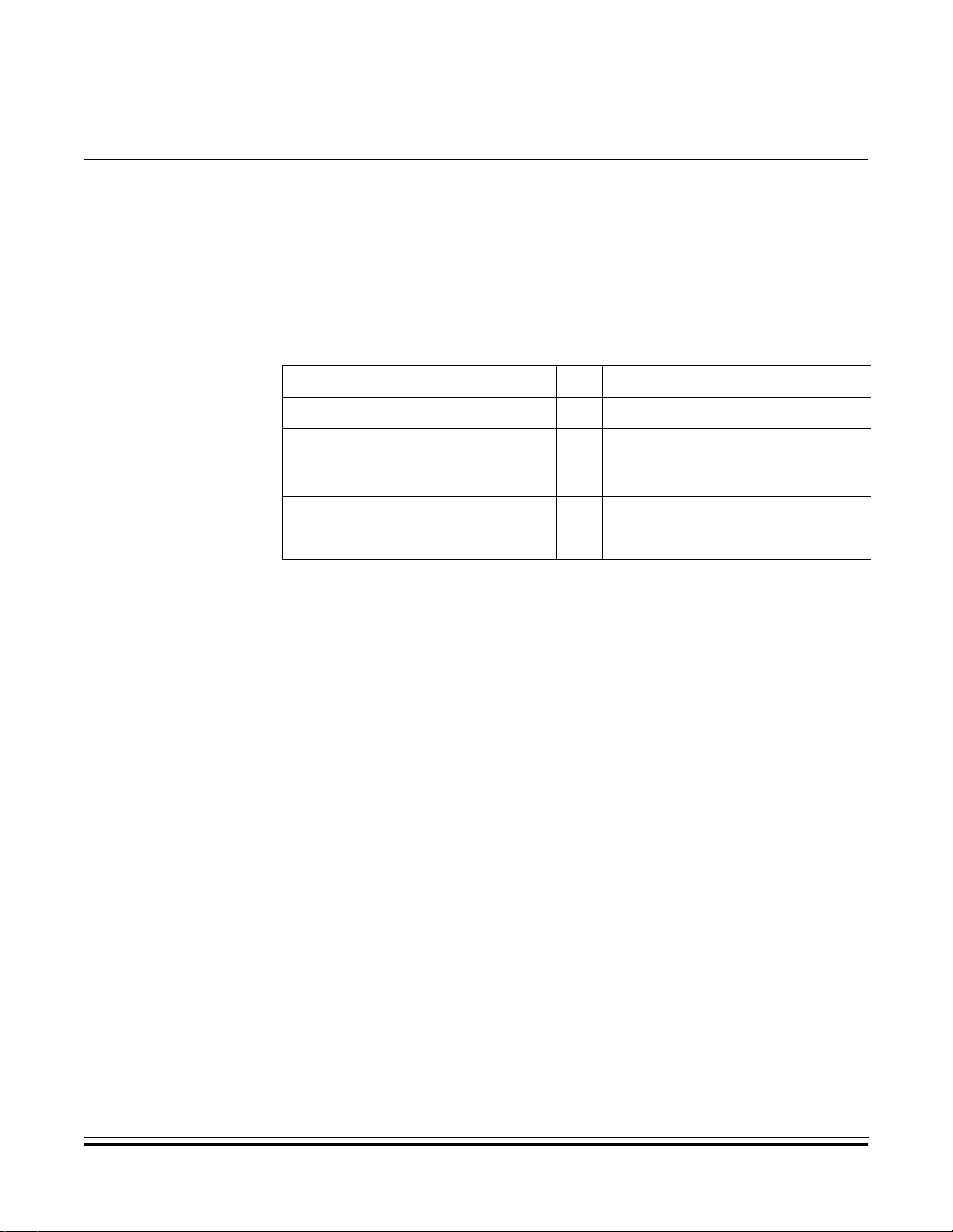
Designer Reference Manual — USB08 Evaluation Board
Appendix A. Supported Standard Device Requests
Definition of the supported standard device requests are given here.
Standard Device Request ID Supported Options
SET_ADDRESS 5 Any
DEVICE
GET_DESCRIPTOR 6
SET_CONFIGURATION 9 0/1
CLEAR_FEATURE 1 ENDPOINT_HALT
CONFIGURATION
STRING
USB08 Evaluation Board Designer Reference Manual
MOTOROLA Supported Standard Device Requests 81
Page 82

Supported Standard Device Requests
Designer Reference Manual USB08 Evaluation Board
82 Supported Standard Device Requests MOTOROLA
Page 83

Designer Reference Manual — USB08 Evaluation Board
Appendix B. USB08 Descriptors
B.1 Contents
B.2 Introduction. . . . . . . . . . . . . . . . . . . . . . . . . . . . . . . . . . . . . . . .83
B.3 Device Descriptor. . . . . . . . . . . . . . . . . . . . . . . . . . . . . . . . . . .84
B.4 Configuration Descriptor. . . . . . . . . . . . . . . . . . . . . . . . . . . . . .84
B.5 Interface Descriptor . . . . . . . . . . . . . . . . . . . . . . . . . . . . . . . . .85
B.6 Endpoint 1 Descriptor. . . . . . . . . . . . . . . . . . . . . . . . . . . . . . . .85
B.7 Endpoint 2 Descriptor. . . . . . . . . . . . . . . . . . . . . . . . . . . . . . . .85
B.8 String Descriptors. . . . . . . . . . . . . . . . . . . . . . . . . . . . . . . . . . .86
B.2 Introduction
This appendix defines the USB08 descriptors.
USB08 Evaluation Board Designer Reference Manual
MOTOROLA USB08 Descriptors 83
Page 84

USB08 Descriptors
B.3 Device Descriptor
const device_descriptor DeviceDesc =
{ // Size of this Descriptor in Bytes
sizeof(device_descriptor),
DT_DEVICE, // Descriptor Type (=1)
{0x10, 0x01}, // USB Spec Release Number in BCD = 1.10
0, // Device Class Code (none)
0, // Device Subclass Code (none)
0, // Device Protocol Code (none)
8, // Maximum Packet Size for EP0
{0x70, 0x0c}, // Vendor ID = MCT Elektronikladen
{0x00, 0x00}, // Product ID = Generic Demo
{0x00, 0x01}, // Device Release Number in BCD
1, // Index of String Desc for Manufacturer
2, // Index of String Desc for Product
0, // Index of String Desc for SerNo
1 // Number of possible Configurations
}; // end of DeviceDesc
B.4 Configuration Descriptor
const configuration_descriptor ConfigDesc =
{ // Size of this Descriptor in Bytes
sizeof(configuration_descriptor),
DT_CONFIGURATION, // Descriptor Type (=2)
{sizeof(con fi gu ration_descriptor) + siz eo f( in terface_descr ip to r) +
sizeof(endpoint_descriptor) + sizeof(endpoint_descriptor),
0x00}, // Total Leng th of Data for this Conf
1, // No of Interfaces supported by this Conf
1, // Designator Value for *this* Configuration
0, // Index of String Desc for this Conf
0xc0, // Self -powered, no Remote-Wakeup
0 // Max. Power Consumption in this Conf (*2mA)
}; // end of ConfigDesc
Designer Reference Manual USB08 Evaluation Board
84 USB08 Descriptors MOTOROLA
Page 85

B.5 Interface Descriptor
const interface_descriptor InterfaceDesc =
{ // Size of this Descriptor in Bytes
sizeof(interface_descriptor),
DT_INTERFACE, // Descriptor Type (=4)
0, // Number of *this* Interface (0..)
0, // Alternative for this Interface (if any)
2, // No of EPs used by this IF (excl. EP0)
0xff, // IF Class Code (0xff = Vendor specific)
0x01, // Inte rface Subclass Code
0xff, // IF Protocol Code (0xff = Vendor specific)
0 // Index of String Desc for this Interface
}; // end of InterfaceDesc
B.6 Endpoint 1 Descriptor
USB08 Descriptors
Interface Descrip to r
const en dpo in t_descriptor Endpoint 1D es c =
{ // Size of this Descriptor in Bytes
sizeof(endpoint_descriptor),
DT_ENDPOINT , // Descripto r Ty pe (=5)
0x81, // Endp oint Address (EP1, IN)
0x03, // Inte rrupt
{0x08, 0x00}, // Max. Endpoint Packet Size
10 // Polling Interval (Interrupt) in ms
}; // end of Endpoint1Desc
B.7 Endpoint 2 Descriptor
const en dpo in t_descriptor Endpoint 2D es c =
{ // Size of this Descriptor in Bytes
sizeof(endpoint_descriptor),
DT_ENDPOINT , // Descripto r Ty pe (=5)
0x02, // Endp oint Address (EP2, OUT)
0x03, // Inte rrupt
{0x08, 0x00}, // Max. Endpoint Packet Size
10 // Polling Interval (Interrupt) in ms
}; // end of Endpoint2Desc
USB08 Evaluation Board Designer Ref erence Manual
MOTOROLA USB08 Descriptors 85
Page 86

USB08 Descriptors
B.8 String Desc r ipt or s
// Language IDs
//-------------#defin e SD0 LE N 4
//--------------
const uc har Str ing0Desc[SD0LEN] = {
// Size, Type
SD0LEN, DT_STRING,
// LangID Codes
0x09, 0x04
};
// Manufacturer String
//-------------------------------------------#defin e SD1 LE N sizeof("MCT Elektroni kl ad en" )*2
//-------------------------------------------const uc har Str ing1Desc[SD1LEN] = {
// Size, Type
SD1LEN, DT_STRING,
// Unicode String
’M’, 0,
’C’, 0,
’T’, 0,
’ ’, 0,
’E’, 0,
’l’, 0,
’e’, 0,
’k’, 0,
’t’, 0,
’r’, 0,
’o’, 0,
’n’, 0,
’i’, 0,
’k’, 0,
’l’, 0,
’a’, 0,
’d’, 0,
’e’, 0,
’n’, 0
};
Designer Reference Manual USB08 Evaluation Board
86 USB08 Descriptors MOTOROLA
Page 87

// Product String
//----------------------------------------------#defin e SD2 LE N sizeof("USB08 Evaluat io n Boa rd ")*2
//----------------------------------------------const uc har Str ing2Desc[SD2LEN] = {
// Size, Type
SD2LEN, DT_STRING,
// Unicode String
’U’, 0,
’S’, 0,
’B’, 0,
’0’, 0,
’8’, 0,
’ ’, 0,
’E’, 0,
’v’, 0,
’a’, 0,
’l’, 0,
’u’, 0,
’a’, 0,
’t’, 0,
’i’, 0,
’o’, 0,
’n’, 0,
’ ’, 0,
’B’, 0,
’o’, 0,
’a’, 0,
’r’, 0,
’d’, 0
};
USB08 Descriptors
String Descriptors
// Table of String Descriptors
//
uchar * con st Str ingDescTable[] = {
String0Desc,
String1Desc,
String2Desc
};
USB08 Evaluation Board Designer Ref erence Manual
MOTOROLA USB08 Descriptors 87
Page 88

USB08 Descriptors
Designer Reference Manual USB08 Evaluation Board
88 USB08 Descriptors MOTOROLA
Page 89

Designer Reference Manual — USB08 Evaluation Board
Appendix C. Source Code Files
C.1 Contents
HC908JB8.H . . . . . . . . . . . . . . . . . . . . . . . . . . . . . . . . . . . . . . . . . . . .90
U08USB.H . . . . . . . . . . . . . . . . . . . . . . . . . . . . . . . . . . . . . . . . . . . . .9 3
U08232.H . . . . . . . . . . . . . . . . . . . . . . . . . . . . . . . . . . . . . . . . . . . . . .96
U08LED.H . . . . . . . . . . . . . . . . . . . . . . . . . . . . . . . . . . . . . . . . . . . . .9 6
U08MAIN.C . . . . . . . . . . . . . . . . . . . . . . . . . . . . . . . . . . . . . . . . . . . .97
U08DESC.C . . . . . . . . . . . . . . . . . . . . . . . . . . . . . . . . . . . . . . . . . . .100
U08USB.C . . . . . . . . . . . . . . . . . . . . . . . . . . . . . . . . . . . . . . . . . . . .104
U08232.C . . . . . . . . . . . . . . . . . . . . . . . . . . . . . . . . . . . . . . . . . . . . .113
U08KEY.C . . . . . . . . . . . . . . . . . . . . . . . . . . . . . . . . . . . . . . . . . . . .116
U08ADC.C . . . . . . . . . . . . . . . . . . . . . . . . . . . . . . . . . . . . . . . . . . . .117
VECJB8.C . . . . . . . . . . . . . . . . . . . . . . . . . . . . . . . . . . . . . . . . . . . .119
CRTSJB8.S . . . . . . . . . . . . . . . . . . . . . . . . . . . . . . . . . . . . . . . . . . .120
USB08.LKF . . . . . . . . . . . . . . . . . . . . . . . . . . . . . . . . . . . . . . . . . . . .121
BUILD.BAT . . . . . . . . . . . . . . . . . . . . . . . . . . . . . . . . . . . . . . . . . . . .121
USB08.MAP . . . . . . . . . . . . . . . . . . . . . . . . . . . . . . . . . . . . . . . . . . .122
USB08.S19 . . . . . . . . . . . . . . . . . . . . . . . . . . . . . . . . . . . . . . . . . . . .125
USB08 Evaluation Board Designer Reference Manual
MOTOROLA Source Code Files 89
Page 90

Source Code Files
HC908JB8.H
#ifnde f __H C0 8_H
#defin e __H C0 8_H1
// Contr ol Re gi ster Definitions for HC90 8JB 8 -- -- ------------- -- -- -- ----------
#defin e _IO _B ASE 0
#defin e _P( of f) *(unsigned char volat il e *) (_ IO_BASE + off)
#define _LP(off) *(unsigned short volatile *)(_IO_BASE + off)
#define PTA _P(0x00)
#define PTB _P(0x01)
#define PTC _P(0x02)
#define PTD _P(0x03)
#define DDRA _P(0x04)
#define DDRB _P(0x05)
#define DDRC _P(0x06)
#define DDRD _P(0x07)
#define PTE _P(0x08)
#define DDRE _P(0x09)
#define TSC _P(0x0A)
//not im ple me nted (0x0B)
#define TCNTH _P(0x0C)
#define TCNTL _P(0x0D)
#define TMODH _P(0x0E)
#define TMODL _P(0x0F)
#define TSC0 _P(0x10)
#define TCH0H _P(0x11)
#define TCH0L _P(0x12)
#define TSC1 _P(0x13)
#define TCH1H _P(0x14)
#define TCH1L _P(0x15)
#define KBSCR _P(0x16)
#define KBIER _P(0x17)
#define UIR2 _P(0x18)
#define UCR2 _P(0x19)
#define UCR3 _P(0x1A)
#define UCR4 _P(0x1B)
#define IOCR _P(0x1C)
#define POCR _P(0x1D)
#define ISCR _P(0x1E)
#define CONFIG _P(0x1F)
#define UE0D0 _P(0x20)
#define UE0D1 _P(0x21)
#define UE0D2 _P(0x22)
#define UE0D3 _P(0x23)
#define UE0D4 _P(0x24)
#define UE0D5 _P(0x25)
#define UE0D6 _P(0x26)
#define UE0D7 _P(0x27)
#define UE1D0 _P(0x28)
#define UE1D1 _P(0x29)
#define UE1D2 _P(0x2A)
Designer Reference Manual USB08 Evaluation Board
90 Source Code Files MOTOROLA
Page 91

#define UE1D3 _P(0x2B)
#define UE1D4 _P(0x2C)
#define UE1D5 _P(0x2D)
#define UE1D6 _P(0x2E)
#define UE1D7 _P(0x2F)
#define UE2D0 _P(0x30)
#define UE2D1 _P(0x31)
#define UE2D2 _P(0x32)
#define UE2D3 _P(0x33)
#define UE2D4 _P(0x34)
#define UE2D5 _P(0x35)
#define UE2D6 _P(0x36)
#define UE2D7 _P(0x37)
#define UADDR _P(0x38)
#define UIR0 _P(0x39)
#define UIR1 _P(0x3A)
#define UCR0 _P(0x3B)
#define UCR1 _P(0x3C)
#define USR0 _P(0x3D)
#define USR1 _P(0x3E)
//not im ple me nted (0x3F)
// 16-Bit Registers:
#define TCNT _LP(0x0C)
#define TMOD _LP(0x0E)
#define TCH0 _LP(0x11)
#define TCH1 _LP(0x14)
Source Code Files
Contents
//-- Bit Mask Definitions ----------------------------------------------------
// Bits in UA DD R:
#define BM_USBEN 0x80 // USB Module Enable
// Bits in UI R0 :
#defin e BM_ EO PIE 0x80 // End-of-Pac ke t Detect Interrup t En ab le
#define BM_RXD2IE 0x10 // EP2 Rx Interrupt Enable
#define BM_TXD1IE 0x08 // EP1 Tx Interrupt Enable
#define BM_TXD0IE 0x02 // EP0 Tx Interrupt Enable
#define BM_RXD0IE 0x01 // EP0 Rx Interrupt Enable
// Bits in UI R1 :
#defin e BM_ EO PF 0x80 // End-of-Packe t Detect Flag
#defin e BM_ RS TF 0x40 // Clear Reset Indi ca tor Bit
#define BM_RXD2F 0x10 // EP2 Data Receive Flag
#define BM_TXD1F 0x08 // EP1 Data Transmit complete Flag
#define BM_TXD0F 0x02 // EP0 Data Transmit complete Flag
#define BM_RXD0F 0x01 // EP0 Data Receive Flag
// Bits in UI R2 :
#defin e BM_ EO PFR 0x80 // End-of-Pac ke t Flag Reset
//#define BM_RSTFR 0x40 // Clear Reset Indicator Bit
#define BM_RXD2FR 0x10 // EP2 Receive Flag Reset
#define BM_TXD1FR 0x08 // EP1 Transmit complete Flag Reset
#define BM_TXD0FR 0x02 // EP0 Transmit complete Flag Reset
#define BM_RXD0FR 0x01 // EP0 Receive Flag Reset
// Bits in UC R0 :
USB08 Evaluation Board Designer Ref erence Manual
MOTOROLA Source Code Files 91
Page 92

Source Code Files
#define BM_T0SEQ 0x80 // EP0 Tx Sequence Bit (DATA0/1)
#define BM_TX0E 0x20 // EP0 Tx Enable
#define BM_RX0E 0x10 // EP0 Rx Enable
//#define BM_TP0SIZ 0x0f // EP0 Tx Data Packe t Size
// Bits in UC R1 :
#define BM_T1SEQ 0x80 // EP1 Tx Sequence Bit (DATA0/1)
#defin e BM_ ST ALL1 0x40 // EP1 Force Stal l Bit
#define BM_TX1E 0x20 // EP1 Tx Enable
//#define BM_TP1SIZ 0x0f // EP1 Tx Data Packe t Size
// Bits in UC R2 :
#defin e BM_ ST ALL2 0x40 // EP2 Force Stal l Bit
#define BM_RX2E 0x10 // EP2 Rx Enable
// Bits in UC R3 :
#define BM_TX1STR 0x40 // Clear EP0 Transmit-1st Flag
#defin e BM_ OS TALL0 0x20 // EP0 force ST AL L Bi t fo r OUT Token
#defin e BM_ IS TALL0 0x10 // EP0 force ST AL L Bi t fo r IN Token
#defin e BM_ PU LLEN 0x04 // Pull-up Enab le
#define BM_ENABLE2 0x02 // EP2 Enable
#define BM_ENABLE1 0x01 // EP1 Enable
// Bits in US R0 :
// #define BM_R0SEQ 0x80 // EP0 Rx Sequence Bit (DATA0/1)
#define BM_SETUP 0x40 // Setup Token Detect Bit
//#define BM_RP0SIZ 0x0f // EP0 Rx Data Packe t Size
// Bits in US R1 :
//#define BM_R2SEQ 0x80 // EP2 Rx Sequence Bit (DATA0/1)
#define BM_RP2SIZ 0x0f // EP2 Rx Data Packet Size
//----------------------------------------------------------------------------
#endif
Designer Reference Manual USB08 Evaluation Board
92 Source Code Files MOTOROLA
Page 93

U08USB.H
//============================================================================
// File: U08_USB.H
// Func: Definitions for USB Data Types & Constants
// Hea der File for USB08 Demo Applic at io n
// Auth: (C)2000 by MCT Elektronikladen GbR, Oliver Thamm
// http://www.elektronikladen.de/mct
// Rem.: View/Edit this File with TAB-Size=4
//============================================================================
//-- Data Type Definitions ---------------------------------------------------
typede f str uc t { // Data Ty pe "In tel Word"
uchar lo; // (High/ Low Byte swapped)
uchar hi ;
} iword;
//----------------------------------------------------------------------------
// Standard Device Descriptor
// accor din g to USB1.1 spec page 197
//
typede f str uc t {
uchar bL eng th ; // Size of thi s Des criptor in Bytes
uchar bD esc ri ptorType; // Descriptor Type (=1)
iword bcdUSB; // USB Spec Release Number in BCD
uchar bD evi ce Class; // Devic e Cl as s Code
uchar bD evi ce SubClass; // Device Subclass Code
uchar bD evi ce Protocol; // Device Protocol Code
uchar bMaxPacketSize0; // Maximum Packet Size for EP0
iword id Ven do r; // Vendo r ID
iword idProduct; // Product ID
iword bc dDe vi ce; // Device Re lease Num be r in BCD
uchar iManufacturer; // Index of String Desc for Manufacturer
uchar iProduct; // Index of String Desc for Product
uchar iSerialNumber; // Index of String Desc for SerNo
uchar bNumConfigurations; // Number of possible Configurations
} device _de sc riptor;
Source Code Files
Contents
//----------------------------------------------------------------------------
// Standard Configuration Descriptor
// accor din g to USB1.1 spec page 199
//
typede f str uc t {
uchar bL eng th ; // Size of thi s Des criptor in Bytes
uchar bD esc ri ptorType; // Descriptor Type (=2)
iword wTotalLength; // Total Length of Data for this Conf
uchar bNumInterfaces; // No of Interfaces supported by this Conf
uchar bConfigurationValue; // Designator Value for *this* Configuration
uchar iConfiguration; // Index of String Desc for this Conf
uchar bm Att ri butes; // Confi gu ra tion Characteristics (se e be lo w)
uchar bM axP ow er; // Max. Powe r Consump ti on in th is Conf (*2mA)
} config ura ti on_descriptor;
USB08 Evaluation Board Designer Ref erence Manual
MOTOROLA Source Code Files 93
Page 94

Source Code Files
//----------------------------------------------------------------------------
// Standard Interface Descripto r
// accor din g to USB1.1 spec page 202
//
typede f str uc t {
uchar bL eng th ; // Size of thi s Des criptor in Bytes
uchar bD esc ri ptorType; // Des cr ip tor Type (=4)
uchar bInterfaceNumber; // Number of *this* Interface (0..)
uchar bAlternateSetting; // Alternative for this Interface (if any)
uchar bNumEndpoints; // No of EPs used by this IF (excl. EP0)
uchar bInterfaceClass; // Interface Class Code
uchar bInterfaceSubClass; // Interface Subclass Code
uchar bInterfaceProtocol; // Interface Protocol Code
uchar iInterface; // Index of String Desc for this Interface
} interf ace _d escriptor;
//----------------------------------------------------------------------------
// Standard Endpoint Descriptor
// accor din g to USB1.1 spec page 203
//
typede f str uc t {
uchar bL eng th ; // Size of thi s Des criptor in Bytes
uchar bD esc ri ptorType; // Des cr ip tor Type (=5)
uchar bEndpointAddress; // Endpoint Address (Number + Direction)
uchar bm Att ri butes; // Endpoint Attribute s (T ra ns fer Type)
iword wMaxPacketSize; // Max. Endpoint Packet Size
uchar bInterval; // Polling Interval (Interrupt) in ms
} endpoi nt_ de scriptor;
//----------------------------------------------------------------------------
// Structure of Setup Packet sent during
// SETUP Stage of Standard Device Requests
// accor din g to USB1.1 spec page 183
//
typede f str uc t {
uchar bm Req ue stType; / / Characteristi cs (D ir ec tion,Type,Recipient )
uchar bR equ es t; // Stand ar d Re quest Code
iword wValue; // Value Field
iword wI nde x; // Ind ex or Of fs et Field
iword wL eng th ; // Numbe r of Byt es to transfer (Data Stage)
} setup_ buf fe r;
//----------------------------------------------------------------------------
// USB Status Codes
//
#defin e US_ AT TACHED 0x 00 // (not used here)
#defin e US_ PO WERED 0x01
#defin e US_ DE FAULT 0x02
#defin e US_ AD DRESSED 0x03
#defin e US_ CO NFIGURED 0x04
#defin e US_ SU SPENDED 0x80
Designer Reference Manual USB08 Evaluation Board
94 Source Code Files MOTOROLA
Page 95

//----------------------------------------------------------------------------
// USB Standard Device Request Codes
// accor din g to USB1.1 spec page 187
//
#defin e GET _S TATUS 0x00
#defin e CLE AR _FEATURE 0x01
#defin e SET _F EATURE 0x 03
#defin e SET _A DDRESS 0x 05
#defin e GET _D ESCRIPTOR 0x06
#define SET DESCRIPTOR 0x07 // optional
#defin e GET _C ONFIGURATION 0x08
#defin e SET _C ONFIGURATION 0x09
#defin e GET _I NTERFACE 0x0a
#defin e SET _I NTERFACE 0x0b
#defin e SYN CH _FRAME 0x 0c // optional
#define REQUEST_COMPLETE 0xff // not part of the Standard - just
// a Flag to indicate that the recent
// Request has been finished
//----------------------------------------------------------------------------
Source Code Files
Contents
// Descriptor Types
// accor din g to USB1.1 spec page 187
//
#defin e DT_ DE VICE 1
#defin e DT_ CO NFIGURATION 2
#defin e DT_ ST RING 3
#defin e DT_ IN TERFACE 4
#defin e DT_ EN DPOINT 5
//----------------------------------------------------------------------------
// Function Prototypes
//
void initUSB();
uchar ge tUS B( );
void putUSB(uchar c);
@inter ru pt vo id isrUSB();
//============================================================================
USB08 Evaluation Board Designer Ref erence Manual
MOTOROLA Source Code Files 95
Page 96

Source Code Files
U08232.H
//============================================================================
// File: U08_232.H
// Func: Header File for RS232 Module of USB08 Demo App
// Ver.: 1.00
// Auth: (C)2000,2001 by Oliver Thamm
// MCT Elektronikladen GbR
// http://hc08web.de/usb08
// Rem.: View/Edit this File with TAB-Size=4
//============================================================================
//-- Function Prototypes -----------------------------------------------------
void initSSCI();
void putSSCI(char c);
char getSSCI();
//============================================================================
U08LED.H
//============================================================================
// File: U08LED.H
// Func: LED Functions for USB08
// Auth: (C)2000 by MCT Elektronikladen GbR, Oliver Thamm
// http://www.elektronikladen.de/mct
//============================================================================
// No code in thi s Mo dule - just Macros!
#defin e ini tL ED() (DDR D |= 0x07 )
#defin e tog gl eLED(x) (PTD ^= (1 << (x- 1) ))
#defin e off LE D(x) (PTD |= (1 << (x-1)))
#defin e onL ED (x) (PTD &= ~(1 << (x -1)))
//============================================================================
Designer Reference Manual USB08 Evaluation Board
96 Source Code Files MOTOROLA
Page 97

U08MAIN.C
//============================================================================
// File: U08MAIN.C
// Func: Main Module for USB08 Demo App lication
// Ver.: 1.00
// Auth: (C)2000,2001 by Oliver Thamm, MCT Elektronikladen GbR
// http://hc08web.de/usb08
// Make: Build the project using U08M AIN.C, U08KEY.C,
// and VECJB8.C, use CRTSJB8.S as C-Startup Module
// Rem.: View/Edit this File with TAB-Size=4
//============================================================================
//-- Select Interface! -------------------------------------------------------
#defin e USE _U SB_PIPE // by defining or NOT defin in g th is
// label before compiling, you can
// select the communication interface
// (if defined => USB, if not => RS232)
//-- Includes ----------------------------------------------------------------
Source Code Files
Contents
#inclu de "hc0 8jb8.h" // HC908JB8 Regi ster and Bi tm ap Def initions
#include "u08key.h" // Keyboard Module Header File
#include "u08led.h" // LED Module Header File (just Macros)
#inclu de "u08 adc.h" // Soft ADC Mo dule Hea der Fil e
//-- Compiler-dependent Stuff ------------------------------------------------
#defin e cli () _asm("cl i")
#defin e nop () _asm("nop")
//-- Data Type Definitions ---------------------------------------------------
typede f uns ig ned char uchar;
//-- Code Starts here --------------------------------------------------------
#ifdef USE_USB_PIPE
#include "u08usb.c" // use USB implementation
#defin e ini tP ipe initUS B
#defin e get Pi pe getUSB
#defin e put Pi pe putUSB
#else
#include "u08232.c" // use RS232 implementation
#defin e ini tP ipe initSS CI
#defin e get Pi pe getSSCI
#defin e put Pi pe putSSCI
@interrupt void isrUSB() { }
#endif
//----------------------------------------------------------------------------
USB08 Evaluation Board Designer Ref erence Manual
MOTOROLA Source Code Files 97
Page 98

Source Code Files
// Things that should be done immedia tely after Reset
// (this is called by the C-Startup Module)
//
void _HC08Setup() {
CONFIG = 0x21; // USB Reset Disable, COP Disable
TSC = 0x00; // clear TSTOP, Prescaler=0
}
//----------------------------------------------------------------------------
// Dummy Interrupt Handler
// Place a Breakpoint here in case you are looking for spurious Interrupts
//
@interrupt void isrDummy() {
nop(); // just fo r De bu gging
}
//----------------------------------------------------------------------------
void main() {
uchar n, a;
uchar io _bu ff er[8];
uchar ad c[3 ];
initPi pe (); // init RS 23 2 or USB Pipe
initLE D( ); // init LE D Ou tp ut
initKe y( ); // init Ke y In pu t
initSA DC (); // init So ft ADC
cli();
a = 0;
while(1) {
// update ADC results (1 out of 3 at one time)
adc[a] = getSADC(a+1);
if(++a == 3) a= 0;
// get data from input pipe
n=0;
do {
io_buf fe r[n ++] = getPipe();
} while( n<8 );
// proce ss in pu t data
if(io_buffer[0]==0) offLED(1);
else onLED(1);
if(io_buffer[1]==0) offLED(2);
else onLED(2);
if(io_buffer[2]==0) offLED(3);
else onLED(3);
Designer Reference Manual USB08 Evaluation Board
98 Source Code Files MOTOROLA
Page 99

// send dat a to out put pipe
io_buf fe r[0 ] = getKey(1);
io_buf fe r[1 ] = getKey(2);
io_buf fe r[2 ] = getKey(3);
io_buf fe r[3 ] = adc[0];
io_buf fe r[4 ] = adc[1];
io_buf fe r[5 ] = adc[2];
n=0;
do {
putPipe(io_buffer[n++]);
} while( n<8 );
}
}
//============================================================================
Source Code Files
Contents
USB08 Evaluation Board Designer Ref erence Manual
MOTOROLA Source Code Files 99
Page 100

Source Code Files
U08DESC.C
//============================================================================
// File: U08DESC.C
// Func: Device-, Configuration- and String-Descriptors for
// USB08 Demo Application (all const Data, placed in Fla sh-ROM)
// Ver.: 1.00
// Auth: (C)2000,2001 by Oliver Thamm, MCT Elektronikladen GbR
// http://hc08web.de/usb08
// Rem.: View/Edit this File with TAB-Size=4
//============================================================================
//----------------------------------------------------------------------------
const device_descriptor DeviceDesc =
{ // Size of this Descriptor in Bytes
sizeof(device_descriptor),
DT_DEVICE, // Descriptor Type (=1)
{0x10, 0x01}, // USB Spec Release Number in BCD = 1.10
0, // Device Class Code (none)
0, // Device Subclass Code(none)
0, // Device Protocol Code (none)
8, // Maximum Packet Size for EP0
{0x70, 0x0c}, // Vendor ID = MCT Elektronikladen
{0x00, 0x00}, // Product ID = Generic Demo
{0x00, 0x01}, // Device Release Number in BCD
1, // Index of String Desc for Manufacturer
2, // Index of String Desc for Product
0, // Index of String Desc for SerNo
1 // Number of possible Configurations
}; // end of DeviceDesc
//----------------------------------------------------------------------------
const configuration_descriptor ConfigDesc =
{ // Size of this Descriptor in Bytes
sizeof(configuration_descriptor),
DT_CONFIGURATION,// Descriptor Type (=2)
{sizeo f( con figuration_descript or ) +s iz eof(interface _d es cr iptor) +
sizeof(endpoint_descriptor) + sizeof(endpoint_descriptor),
0x00}, // Total Length of Data for this Conf
1, // No of Interfaces supported by this Conf
1, // Designator Value for *this* Conf iguration
0, // Index of String Desc for this Conf
0xc0, // Self-powered, no Remote-Wakeup
0 // Max. Power Consumption in this Conf (*2mA)
}; // end of ConfigDesc
//----------------------------------------------------------------------------
Designer Reference Manual USB08 Evaluation Board
100 Source Code Files MOTOROLA
 Loading...