

MOTOROLA SN74LS645H, SN74LS645N, SN74LS640DW, SN74LS640DWR2, SN74LS640H Datasheet
...
Semiconductor Components Industries, LLC, 1999
December, 1999 – Rev. 6
1 Publication Order Number:
SN74LS640/D
SN74LS640 SN74LS641
SN74LS642 SN74LS645
Octal Bus Transceivers
These octal bus transceivers are designed for asynchronous
two-way communication between data buses. Control function
implementation minimizes external timing requirements. These
circuits allow data transmission from the A bus to B or from the B bus
to A bus depending upon the logic level of the direction control (DIR)
input. Enable input (G
) can disable the device so that the buses are
effectively isolated.
DEVICE OUTPUT LOGIC
LS640 3-State Inverting
LS641 Open-Collector True
LS642 Open-Collector Inverting
LS645 3-State True
FUNCTION TABLE
CONTROL
OPERATION
INPUTS
G DIR
LS640
LS642
LS641
LS645
L L B data to A bus B data to A bus
L H A data to B bus A data to B bus
H X Isolation Isolation
H = HIGH Level, L = LOW Level, X = Irrelevant
GUARANTEED OPERATING RANGES (SN74LS640, SN74LS645)
Symbol Parameter Min Typ Max Unit
V
CC
Supply Voltage 4.75 5.0 5.25 V
T
A
Operating Ambient
T emperature Range
0 25 70 °C
I
OH
Output Current – High
–3.0 mA
–15 mA
I
OL
Output Current – Low 24 mA
GUARANTEED OPERATING RANGES (SN74LS641, SN74LS642)
Symbol Parameter Min Typ Max Unit
V
CC
Supply Voltage 4.75 5.0 5.25 V
T
A
Operating Ambient
T emperature Range
0 25 70 °C
V
OH
Output Voltage – High 5.5 V
I
OL
Output Current – Low 24 mA
LOW
POWER
SCHOTTKY
Device Package Shipping
ORDERING INFORMATION
SN74LS640N 16 Pin DIP 1440 Units/Box
SN74LS640DW 16 Pin
SOIC
DW SUFFIX
CASE 751D
http://onsemi.com
2500/Tape & Reel
PLASTIC
N SUFFIX
CASE 738
20
1
20
1
SN74LS641N 16 Pin DIP 1440 Units/Box
SN74LS641DW 16 Pin
2500/Tape & Reel
SN74LS642N 16 Pin DIP 1440 Units/Box
SN74LS642DW 16 Pin
2500/Tape & Reel
SN74LS645N 16 Pin DIP 1440 Units/Box
SN74LS645DW 16 Pin
2500/Tape & Reel
SN74LS640 SN74LS641 SN74LS642 SN74LS645
http://onsemi.com
2
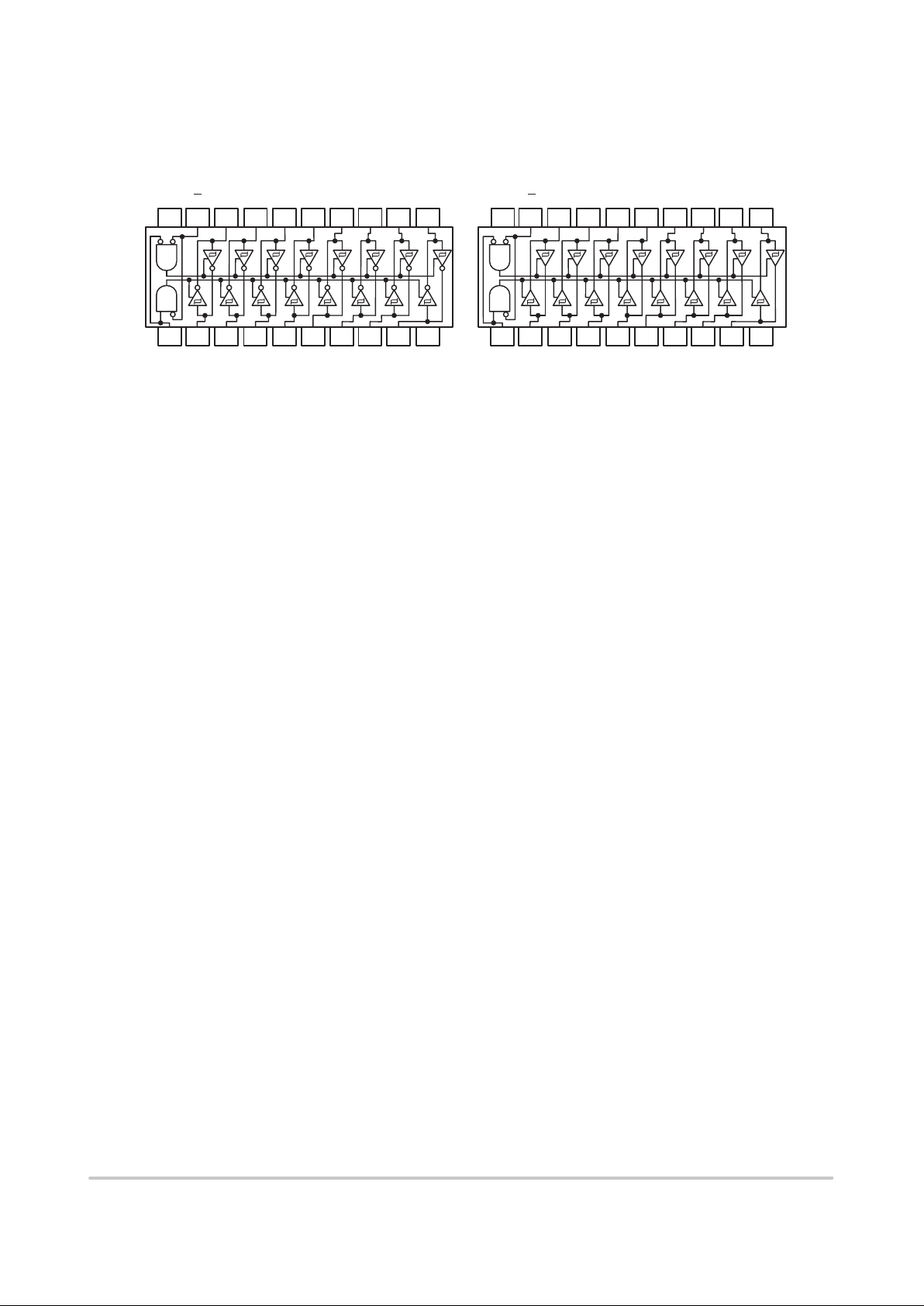
CONNECTION DIAGRAMS DIP (TOP VIEW)
18 17 16 15 14 13
123456
7
20 19
8
V
CC
DIR
B1 B2 B3 B5B4 B6
A1 A2 A3 A4 A5 A6 A7
910
A8 GND
12 11
B7 B8
18 17 16 15 14 13
123456
7
20 19
8
V
CC
DIR
B1 B2 B3 B5B4 B6
A1 A2 A3 A4 A5 A6 A7
910
A8 GND
12 11
B7 B8
SN74LS640
SN74LS642
SN74LS641
SN74LS645
ENABLE
G
ENABLE
G

SN74LS640 SN74LS641 SN74LS642 SN74LS645
http://onsemi.com
3
SN74LS640 • SN74LS645
DC CHARACTERISTICS OVER OPERATING TEMPERATURE RANGE (unless otherwise specified)
Limits
Symbol Parameter
Min Typ Max
Unit Test Conditions
V
IH
Input HIGH Voltage 2.0 V
Guaranteed Input HIGH Voltage for
All Inputs
V
IL
Input LOW Voltage
0.6
V
Guaranteed Input LOW Voltage for
All Inputs
V
IK
Input Clamp Diode Voltage –0.65 –1.5 V VCC = MIN, IIN = –18 mA
p
2.4 3.4 V VCC = MIN, IOH = 3.0 mA
VOHOutput HIGH Voltage
2.0 V
VCC = MIN, IOH = MAX
p
0.25 0.4 V IOL = 12 mA
VCC = VCC MIN,
VOLOutput LOW Voltage
0.35 0.5 V IOL = 24 mA
V
IN
=
V
IL
or
V
IH
per Truth Table
I
OZH
Output Off Current HIGH 20 µA VCC = MAX, V
OUT
= 2.7 V
I
OZL
Output Off Current LOW –400 µA VCC = MAX, V
OUT
= 0.4 V
A or B, DIR or G
20 µA VCC = MAX, VIN = 2.7 V
I
IH
Input HIGH Current
DIR or G
0.1 mA VCC = MAX, VIN = 7.0 V
A or B
0.1 mA VCC = MAX, VIN = 5.5 V
I
IL
Input LOW Current –0.4 mA VCC = MAX, VIN = 0.4 V
I
OS
Output Short Circuit Current (Note 1) –40 –225 mA VCC = MAX
Power Supply Current
Total Output HIGH
70
I
CC
Total, Output LOW
90
m
A
V
CC
=
MAX
Total at HIGH Z
95
Note 1: Not more than one output should be shorted at a time, nor for more than 1 second.
AC CHARACTERISTICS (T
A
= 25°C, VCC = 5.0 V)
Limits
LS640 LS645
Symbol Parameter
Min Typ Max Min Typ Max
Unit Test Conditions
t
PLH
t
PHL
Propagation Delay
A to B
6.0
8.01015
8.01115
15
ns
t
PLH
t
PHL
Propagation Delay
B to A
6.0
8.01015
8.01115
15
ns
CL = 45 pF,
t
PZL
t
PZH
Output Enable Time
G
, DIR to A
312340
40
312640
40
ns
L
RL = 667 Ω
t
PZL
t
PZH
Output Enable Time
G
, DIR to B
312340
40
312640
40
ns
t
PLZ
t
PHZ
Output Disable Time
G
, DIR to A
151525
25
151525
25
ns
p
t
PLZ
t
PHZ
Output Disable Time
G
, DIR to B
151525
25
151525
25
ns
C
L
= 5.0
pF
 Loading...