

Motorola Nexus 6 Service Manual
1
11/17/2014
Initial release.
2
03/16/2015
Updated Rear Inlay Removal procedure and added Rear Inlay Preparation
procedure.
The phone components may be damaged by electrostatic discharge (ESD). Always use an ESD mat and ground strap
when working with internal components.
Handle Battery with care. Ensure Battery edges and surfaces are not dented or deformed. If the Battery Pack is dropped
to the floor, it may be internally damaged and must be scrapped.
Ensure all surfaces, fixtures, and phone components contacting the Battery are smooth and clean.
Ensure Battery and its insulation are not damaged (e.g. scratched, dented, punctured) prior to and throughout
assembly.
Prior to assembly, ensure Battery edges and surfaces are not dented or deformed, and that fixtures and parts that
will contact the Battery are free of foreign material.
Ensure screws and screwdrivers do not contact the Battery.
Failure to adhere to Safety Critical Note(s) may increase risk of rupture, burning, or failure to function safely when
used by the customer.
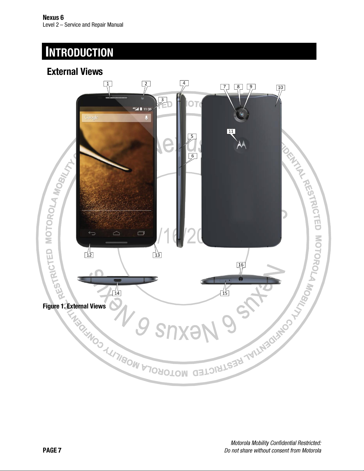
1
Earpiece
2
Front-Facing Imager
3
Main Display
4
Notification LED
5
Power Key
6
Volume Key
7
Flash Ring
8
Imager Lens
9
Rear-Facing Imager
10
Inlay
11
Motorola Medallion
12
Front Housing
13
Rear Housing
14
USB Port
15
SIM Card Tray
16
Headset Jack
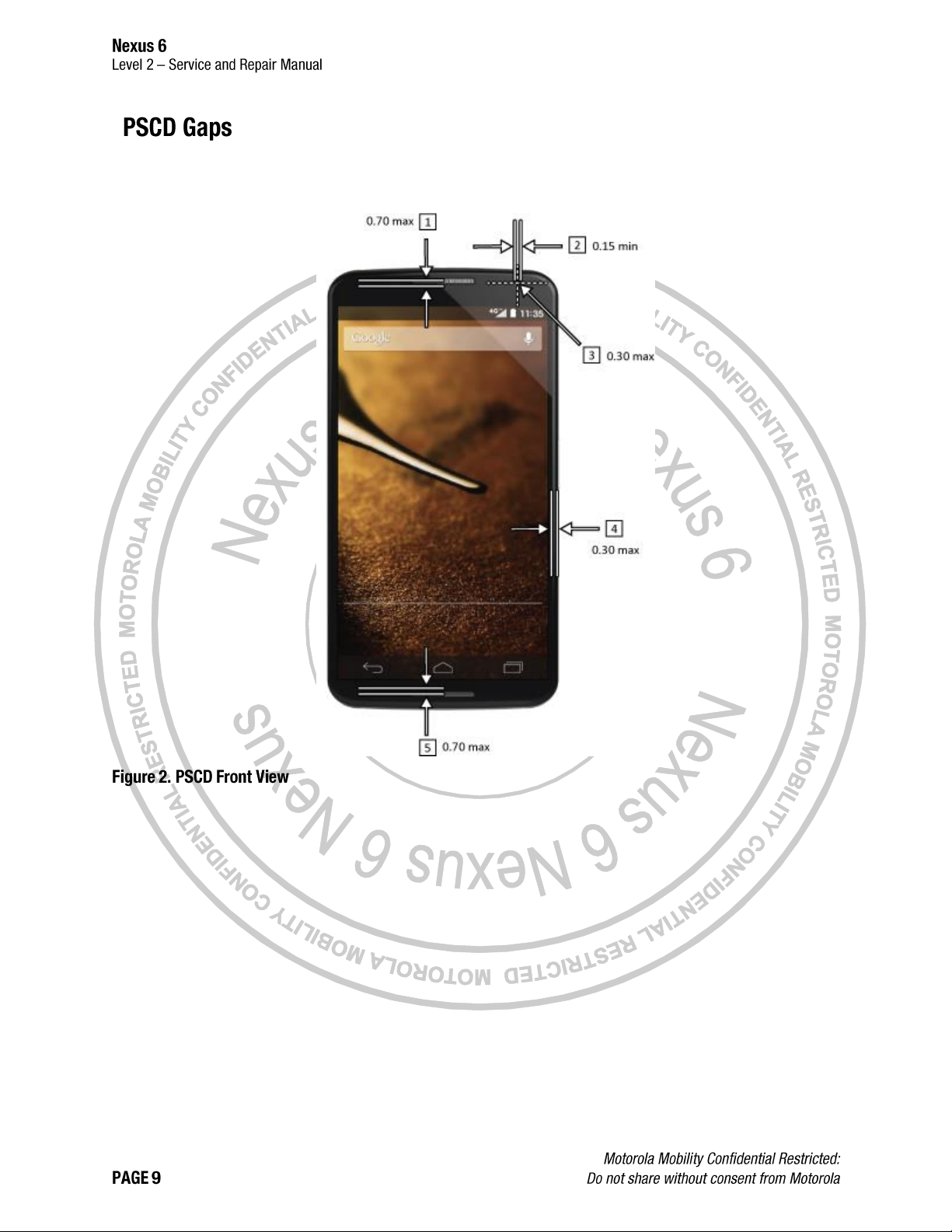
All dimensions are in millimeters (mm). The following gaps are considered maximum allowable without further approval
from a supervisor. Measure gaps at an angle perpendicular to the surface/area being measured. Feeler Gauges must
not be used at an angle as they will give false-positive results.
1
Main Lens to Earpiece Deco Perimeter
2
Front-Facing Imager to Foam Gasket Perimeter
3
Front-Facing Imager Lens Artwork Concentricity
4
Front Housing to Main Lens Perimeter
5
Main Lens to Earpiece Deco Perimeter (Top and Bottom)
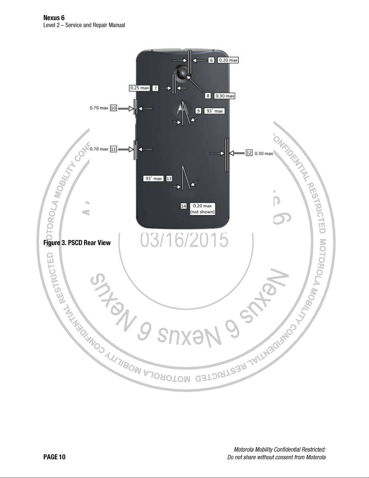
6
LED Flash Lens to Rear-Facing Imager Perimeter
7
Rear Inlay to Flash Lens Perimeter
8
Rear-Facing Imager Center to Lens Artwork Center
9
M Logo to Endo Rear Housing
10
Power Key to Endo Rear Housing
11
Volume Key to Endo Rear Housing
12
Endo Rear Housing to Rear Inlay
13
Branding (not shown) to Endo Rear Housing
14
Letters (not shown) to Rear Inlay Pocket Perimeter
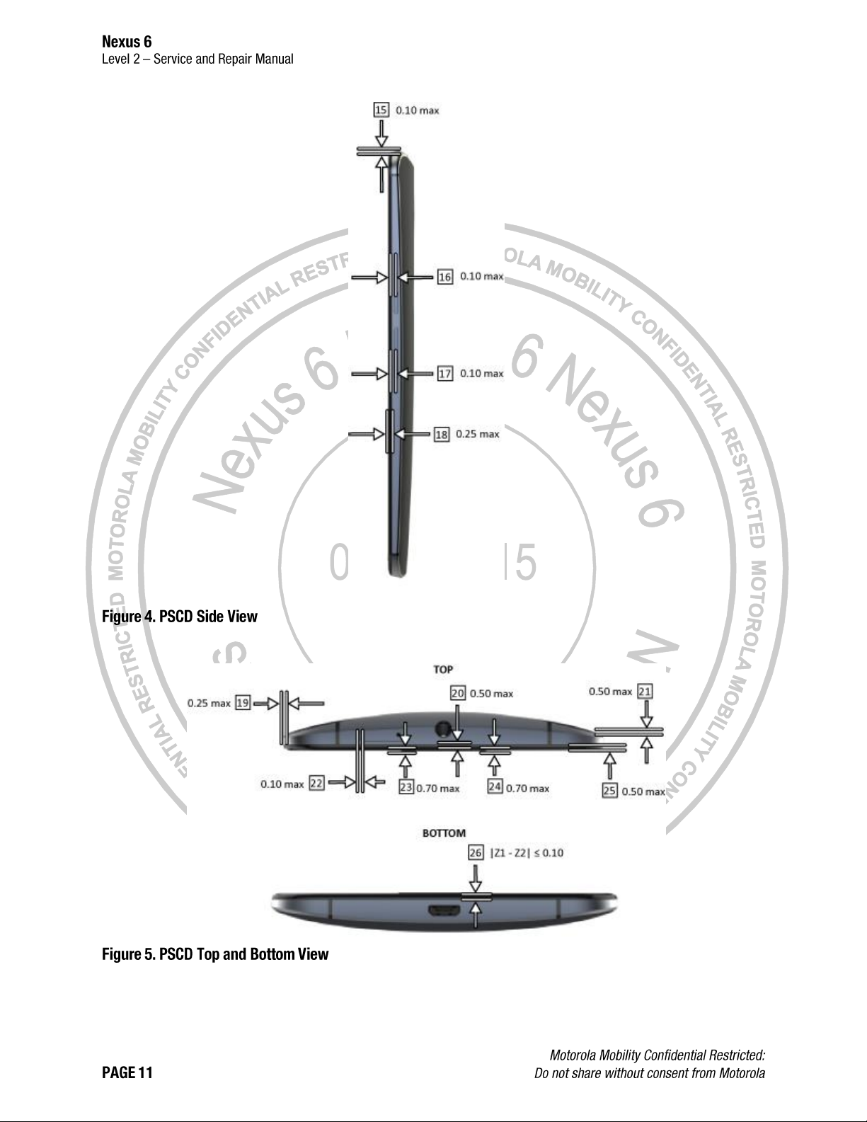
15
SIM Tray Recess
16
Endo Rear Housing to Power Key
17
Endo Rear Housing to Volume Key
18
Front Housing to Endo Rear Housing (Top, Sides, and Bottom)
19
Front Housing to Endo Rear Housing (X,Y) in Front View (at parting line)
20
Front Housing to Endo Rear Housing (Perimeter)
21
Rear Inlay to Endo Rear Housing
22
Endo Rear Housing to SIM Tray
23
Z2 Main Lens to Earpiece Deco (Top and Bottom)
24
Z1 Main Lens to Earpiece Deco (Top and Bottom)
25
Lens Protrusion Over Front Housing
26
Z1 Main Lens to Earpiece Deco (Top and Bottom)
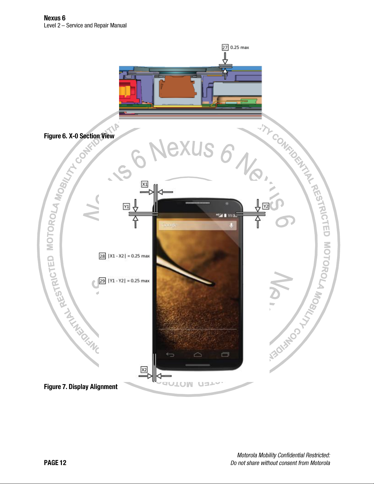
27
Rear inlay to Flash Lens
28
Main Display Alignment X Skew
29
Main Display Alignment Y Skew
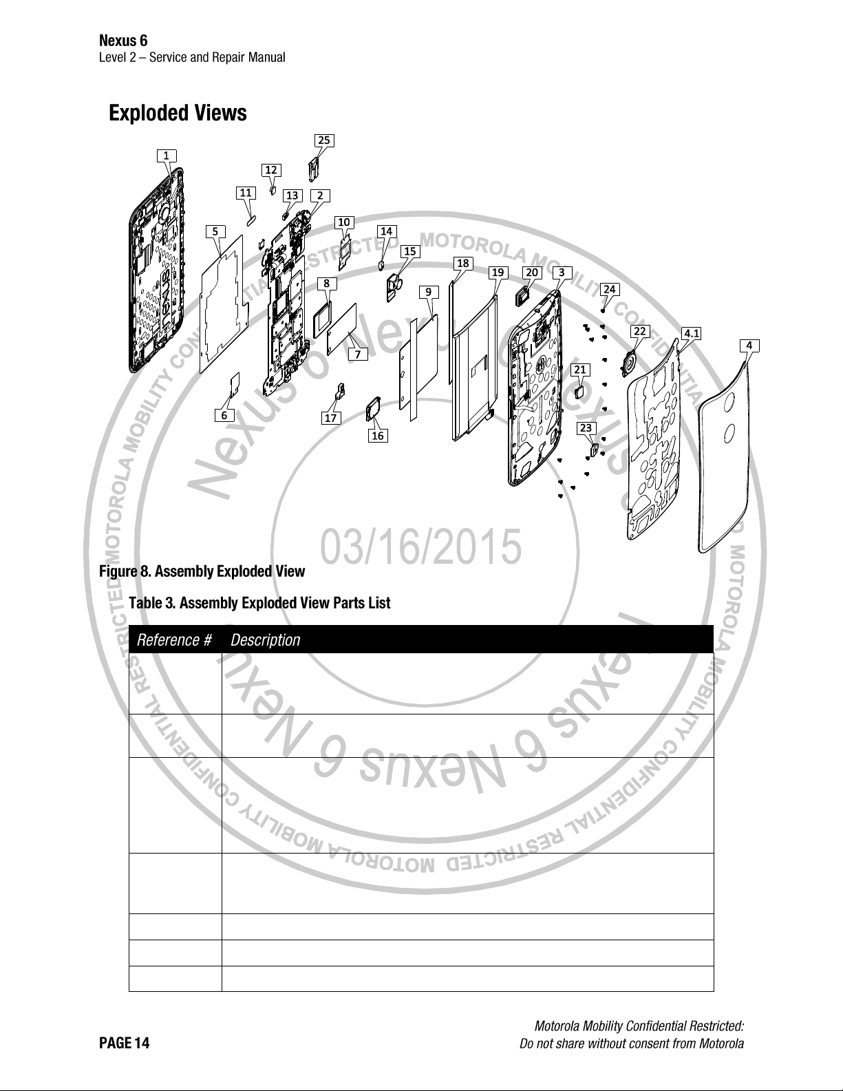
1
ASSEMBLY,HSG,FRNT,LENS,XPLAY,BLACK,B
ASSY,HSG,FRNT,LENS,XPLAY,BLACK,SZ
ASSY,HSG,FRNT,LENS,XPLAY,MP
2
ASSEMBLY,PWA,XPLAY,32GB,AMERICAS
ASSEMBLY,PWA,XPLAY,32GB,ROW
3
ASSEMBLY,HSG,REAR,INNER,XPLAY,DARK,32GB FPR (3)
ASSEMBLY,HSG,REAR,INNER,SUB,XPLAY,LIGHT, FOXCONN
ASSEMBLY,HSG,REAR,INNER,SUB,XPLAY,DARK, FOXCONN
ASSEMBLY,HSG,REAR,INNER,SUB,XPLAY,DARK, FOXCONN
ASSEMBLY,HSG,REAR,INNER,SUB,XPLAY,LIGHT, FOXCONN
4
ASSEMBLY,HOUSING,REAR,INLAY,RESIN,INK
HOUSING,REAR,INLAY,RESIN,DECORATED,RASPBERRY
ASSEMBLY,HOUSING,REAR INLAY,RESIN,CHALK
4.1
DIE CUT, ADHESIVE, REAR INLAY, BORDER, XPLAY
5
TAPE,TOP,THERMAL SPREADER,MAIN PCB
6
PROTIVE LINER,POLY SPEAKRE FAC
7
TAPE,COPPER,APQ,VALOCIA
8
SHIELD,APQ CVR VALOCIA
9
HEAT SPREADER,MAIN PCB THERMAL,XPLAY
10
SEAL,POLY,TOP
11
TAPE,KAPTON,DISPLAY FLX
12
ASSEMBLY,FLXCKT,CAMERA, FRONT FACING
13
GROMMET,PROXIMITY,XPLAY
14
GROMMET,MIC-2
15
ASSEMBLY,13MP OIS CAMERA
16
TRANSDUCER,OTHR,2.2V,AAC W/ ADHES W/ LINER
17
GROMMET,UUSB,VALOCIA
18
TAPE,INSULATION BATTERY, XPLAY
19
ASSEMBLY,BATTTERY,EZ30,LI POLYMER,LG CHEM, MIN 3025 MAH
20
ASSEMBLY,SPEAKER,11X15 POLYPHONIC
21
STOPPER,BRIDGE FLEX CONNECTOR,XPLAY
22
ASSEMBLY,LENS FLASH,XPLAY
23
SPACER,CONNECTOR,BATTERY,VALOCIA
24
SCREW,M1.4,ENDO,X+1
25
ASSEMBLY,SIM DOOR DARK,XPLAY
ASSEMBLY,SIM DOOR LIGHT,XPLAY
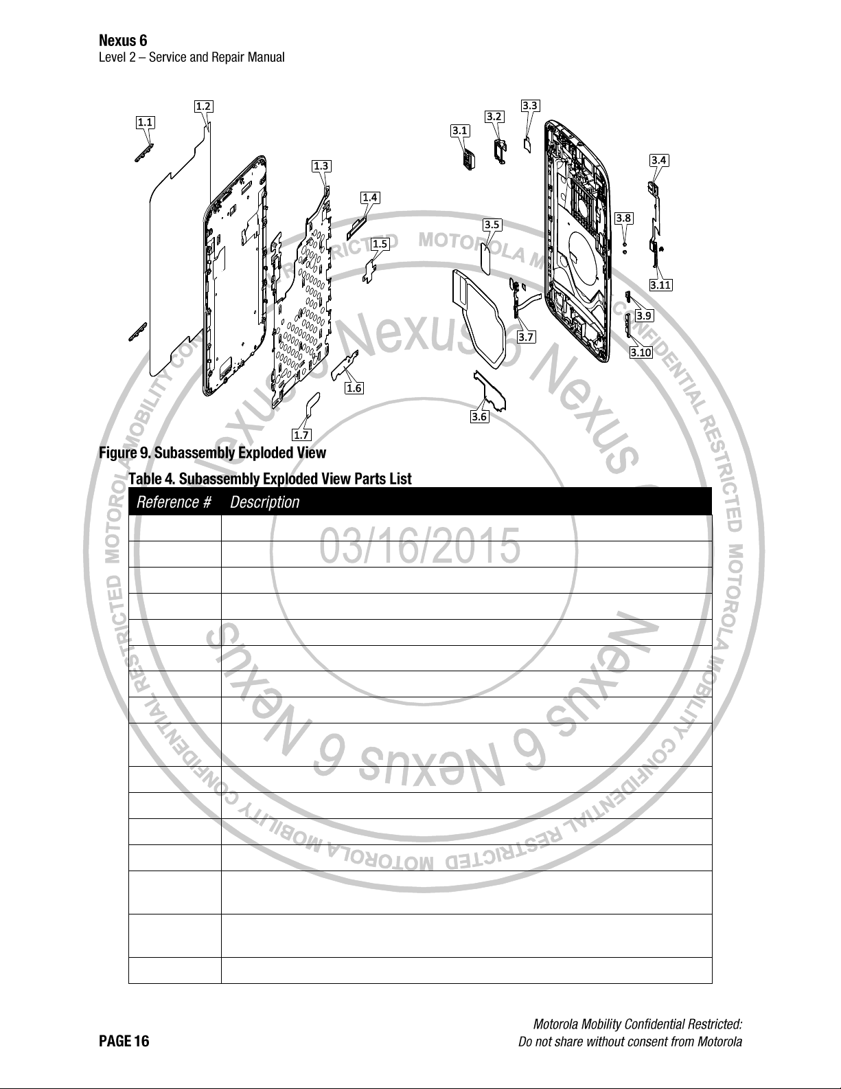
1.1
BEZEL,DECO SPEAKER DARK,XPLAY
1.3
ASSEMBLY,GROUND,PLATE,XPLAY
1.4
SEAL,FRONT,TOP,SPEAKER
1.6
SEAL,BOTTOM SPEAKER AND MIC
1.7
DIE CUT,ADHES,ACSTC GND PLT
3.1
CONN,JACK,HEADSET,3.5 MM DIA
3.2
GROMMET,HSJ,X+1
3.3
DIE CUT,ADHESIVE,HJS,X+1
3.4
ASSY,FLXCKT,BRIDGE FPCB,XPLAY
ASSY,FLXCKT,BRIDGE FPCB,XPLAY
3.5
DIE CUT,ADHESIVE,BATTERY,XPLAY
3.6
SEAL,POLY,BOTTOM
3.7
ASSEMBY,FLXCKT,FLEX,VOLUME,KEY,X+1
3.8
CUSHION,PAD,POWER KEY,X1
3.9
POWER KEY,DARK,XPLAY
POWER KEY,LIGHT,XPLAY
3.10
KEY,VOLUME,DARK,XPLAY
KEY,VOLUME,LIGHT,XPLAY
3.11
SUPPRRT,METAL,HOLDER, VOLUME,KEY,X+1
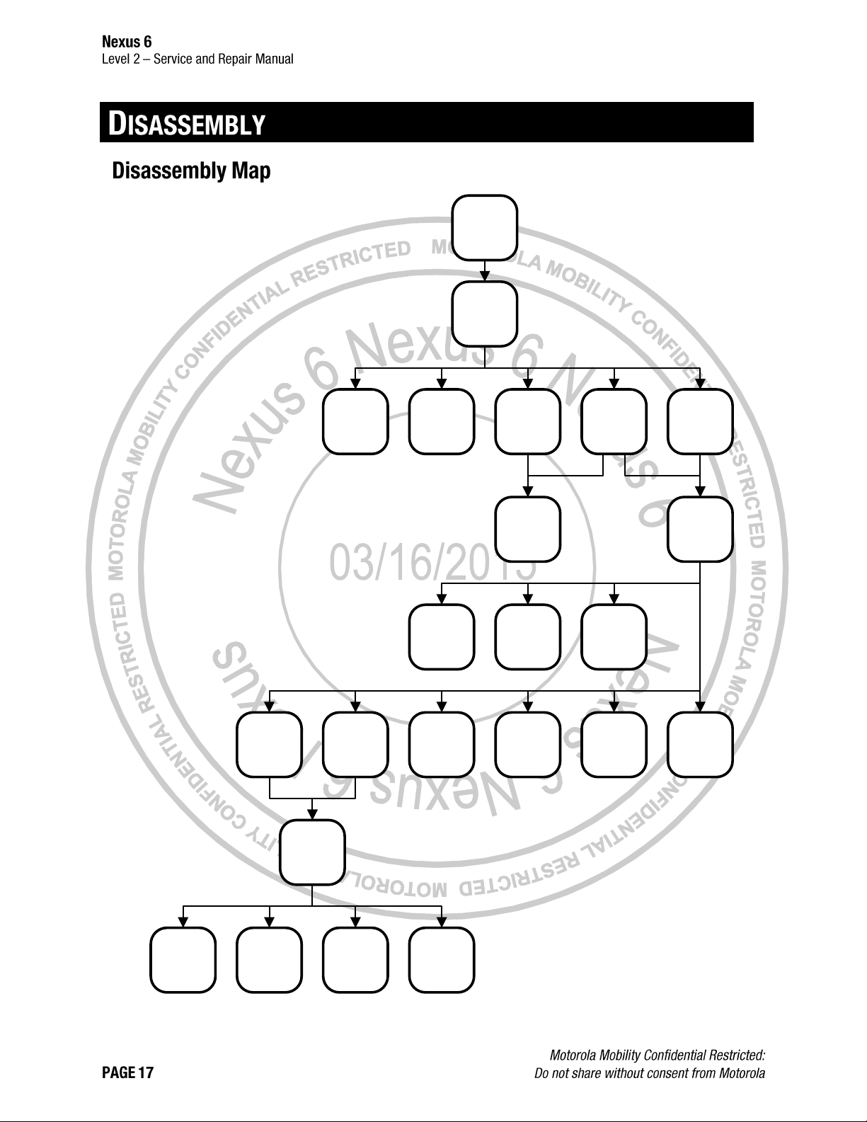
Rear Inlay
SIM Tray
Battery
Disconnection
Bridge Flex
Disconnection
Rear Housing
Flash Lens
Side Key Flex
Disconnection
Bridge Flex
Side Keys
BatteryHeadset Jack
Thermal
Spreader
Kapton Tape
and Grommets
Front-Facing
Imager
Display Flex
Disconnection
Touch Flex
Disconnection
Rear-Facing
Imager
PCB
Proximity
Grommet
Front Housing
Earpiece
Loudspeaker
Earpiece
Gasket
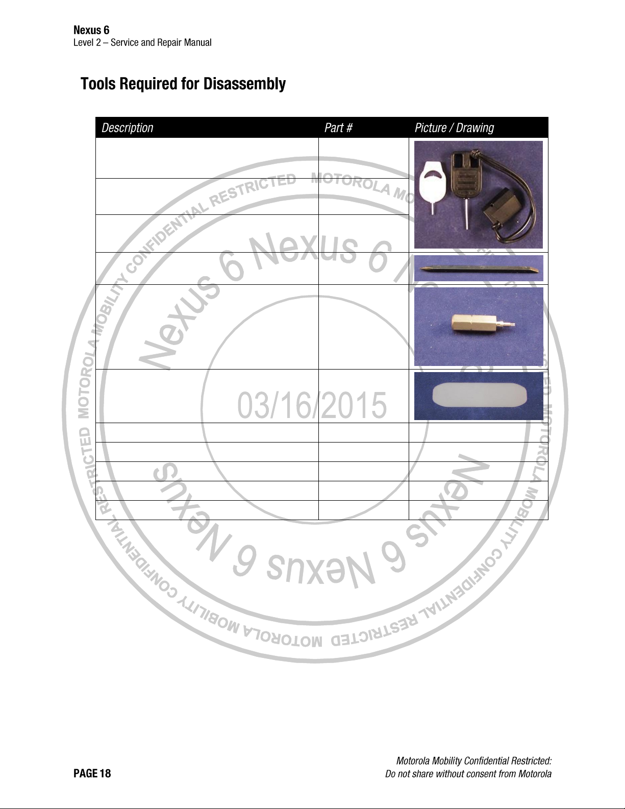
The following tools are required to disassemble the Nexus 6 phone.
SIM Tray Removal Tool
4-00-U2-10000
Inlay Pin Guide
4-00-U2-10000
Inlay Ejection Pin
4-00-U2-10000
Blackstick
--
3IP Torx Bit
-Thin Plastic Spudger
--
Heat Gun
--
--
Tweezers (Plastic or Plastic-Tipped)
--
--
ESD Mat and Wrist Strap
--
--
Gloves or Finger Collets
--
--
Isopropyl (ISP) Alcohol
--
--
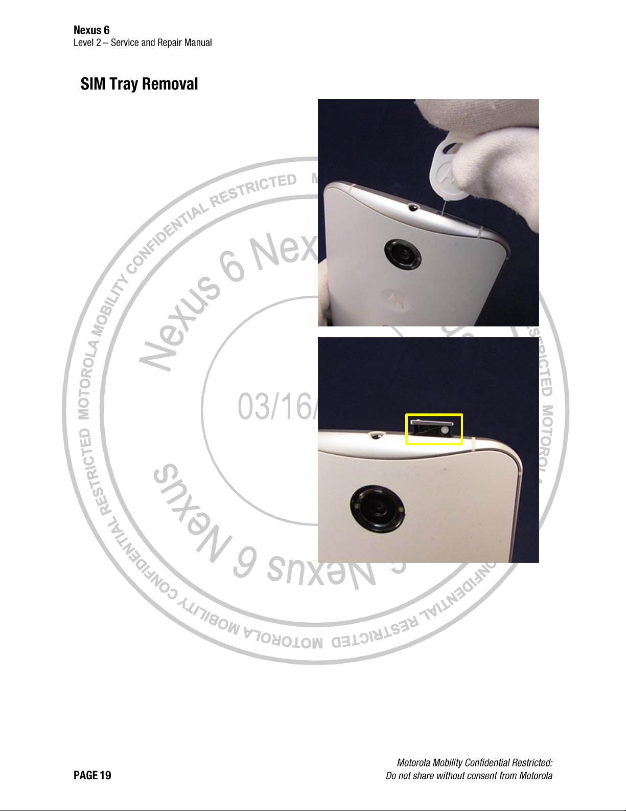
1. Insert the SIM Tray Removal Tool into the SIM
Tray hole.
2. Push the SIM Tray Removal Tool into the SIM
Tray hole until the SIM Tray ejects from the
phone. The white dot is completely visible when
the SIM Tray retaining clips have released.
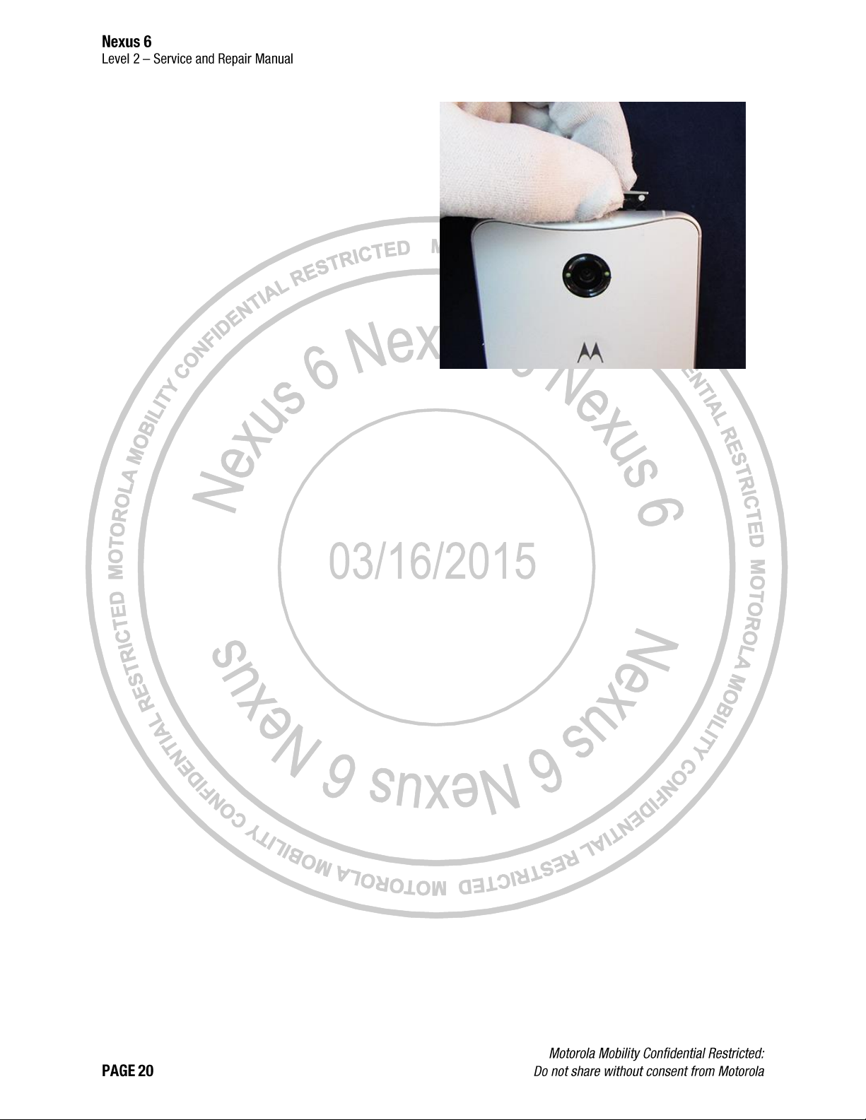
3. Remove the SIM Tray from the phone.
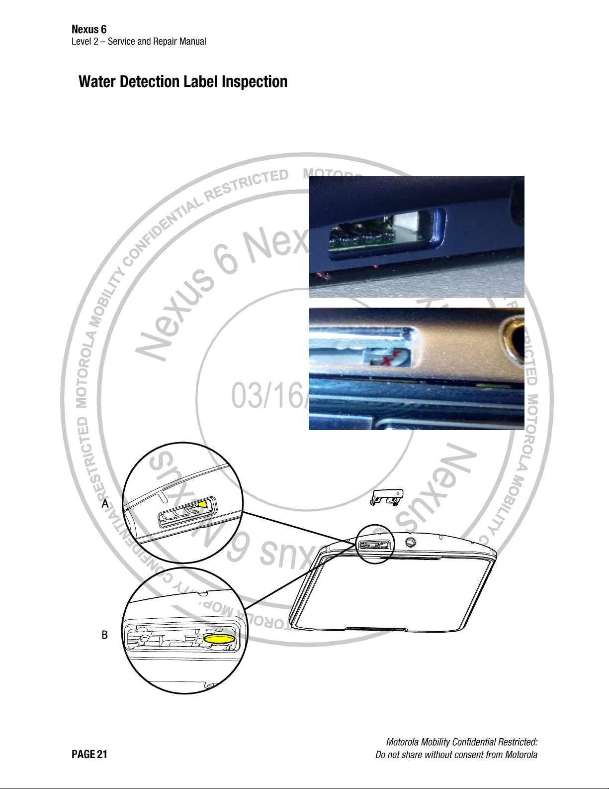
Inspect the Water Detection Label (WDL) visible
through the SIM Tray opening, as shown below,
to verify it is correctly placed and inspect it for
signs of activation. The WDL is in one of two
locations in the SIM tray.
Location A
Location B
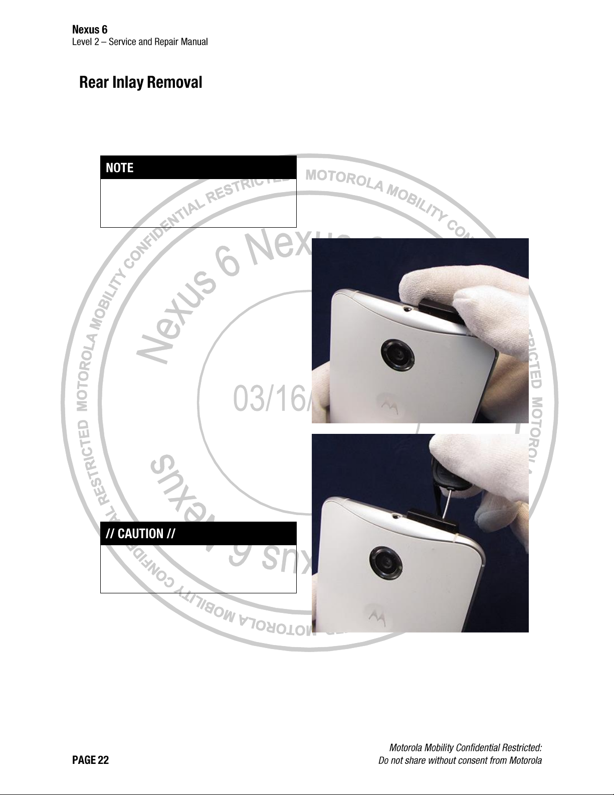
1. Use the Heat Gun to heat the Rear Inlay to a
maximum temperature of 120˚ F (49˚ C) for 2
minutes. The Heat Gun must be held
approximately 4 in. (10 cm) from the Rear Inlay.
Complete this step only if the Rear Inlay will be
reused. If the Rear Inlay will not be reused, skip
this step.
2. Insert the Inlay Pin Guide into the SIM Tray slot.
3. Insert the Inlay Ejection Pin into the guide hole
on the Inlay Pin Guide.
4. Push the Inlay Ejection Pin until it lifts the Inlay
away from the Rear Housing to allow the Thin
Plastic Spudger to be inserted under the Rear
Inlay.
Do not insert the Inlay Ejection Pin farther than
necessary to allow the Thin Plastic Spudger to be
inserted. Damage to the Rear Inlay may occur.
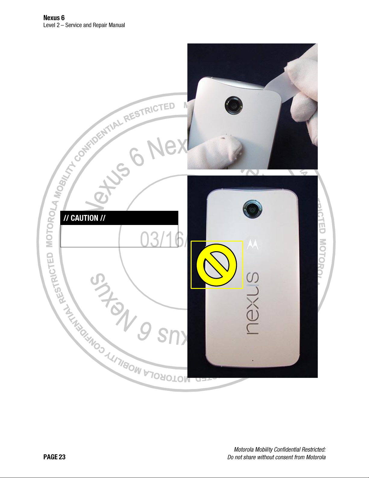
5. Insert the Thin Plastic Spudger in the gap
created by the Inlay Ejection Pin.
6. Move the Thin Plastic Spudger around the
perimeter of the Rear Inlay to loosen the
adhesive between the Rear Inlay and Rear
Housing.
To avoid damaging the Bridge Flex, do not use the
Thin Plastic Spudger in the indicated area.
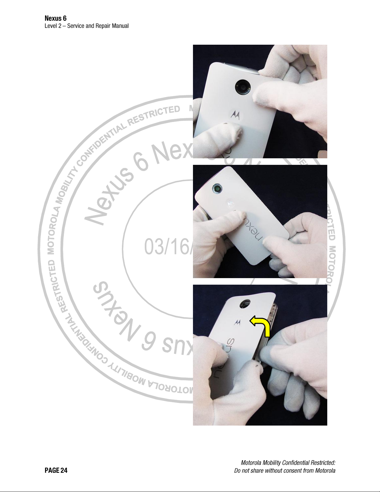
7. Lift the top edge of the Rear Inlay to separate the
adhesive from the Rear Housing. Maintain thumb
pressure on the center of the Rear Inlay while
lifting the top edge.
8. Lift the bottom edge of the Rear Inlay to separate
the adhesive from the Rear Housing. Maintain
thumb pressure on the center of the Rear Inlay
while lifting the bottom edge.
9. Lift the side of the Rear Inlay opposite of the
Side Keys and remove it from the Rear Housing.
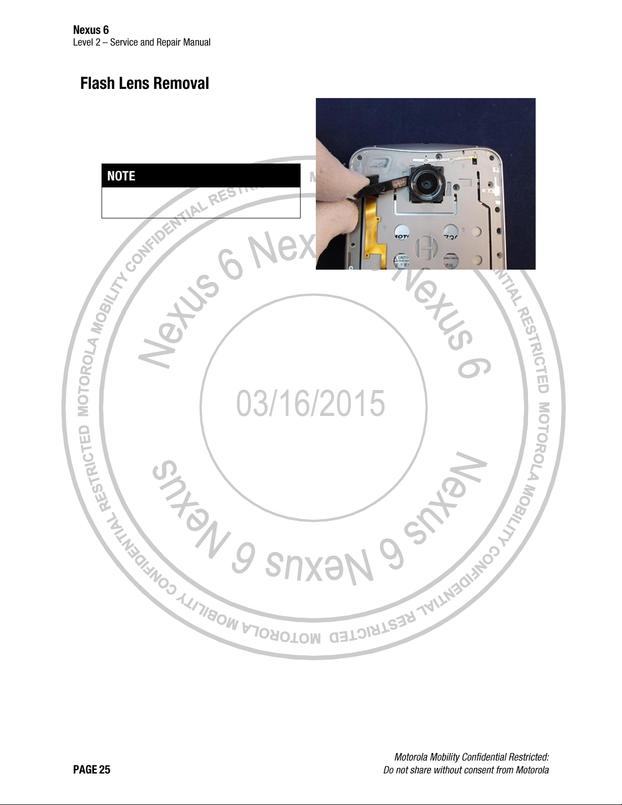
1. Insert the flat end of the Blackstick under the
removal feature on the Flash Lens.
2. Remove the Flash Lens from the Rear Housing
by prying up with the Blackstick.
Remove the Flash Lens only if necessary.
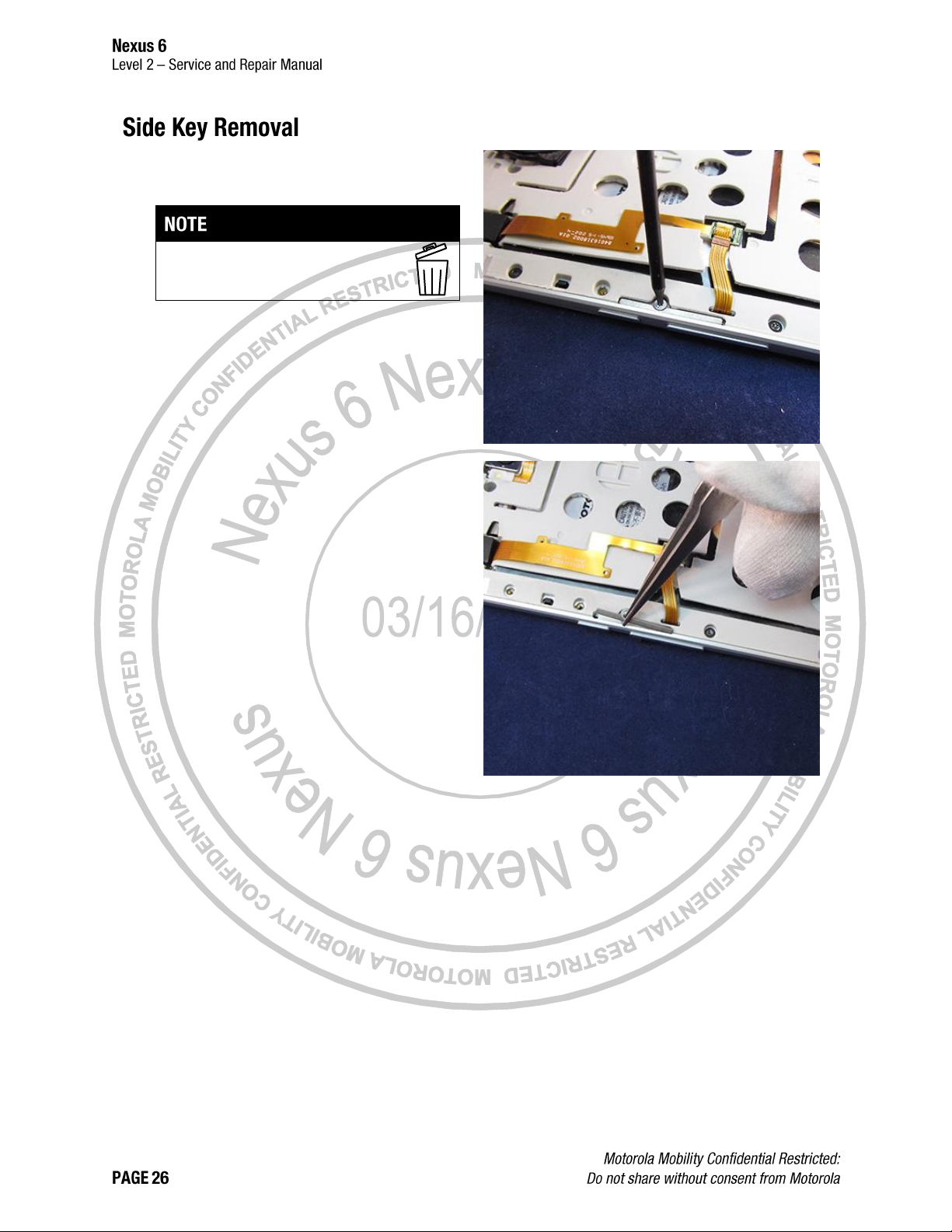
1. Remove the 3IP Screw holding the Side Key
Retention Bracket in place.
After you remove the 3IP Screw, you
cannot reuse it.
2. Use the Tweezers to remove the Side Key
Retention Bracket.
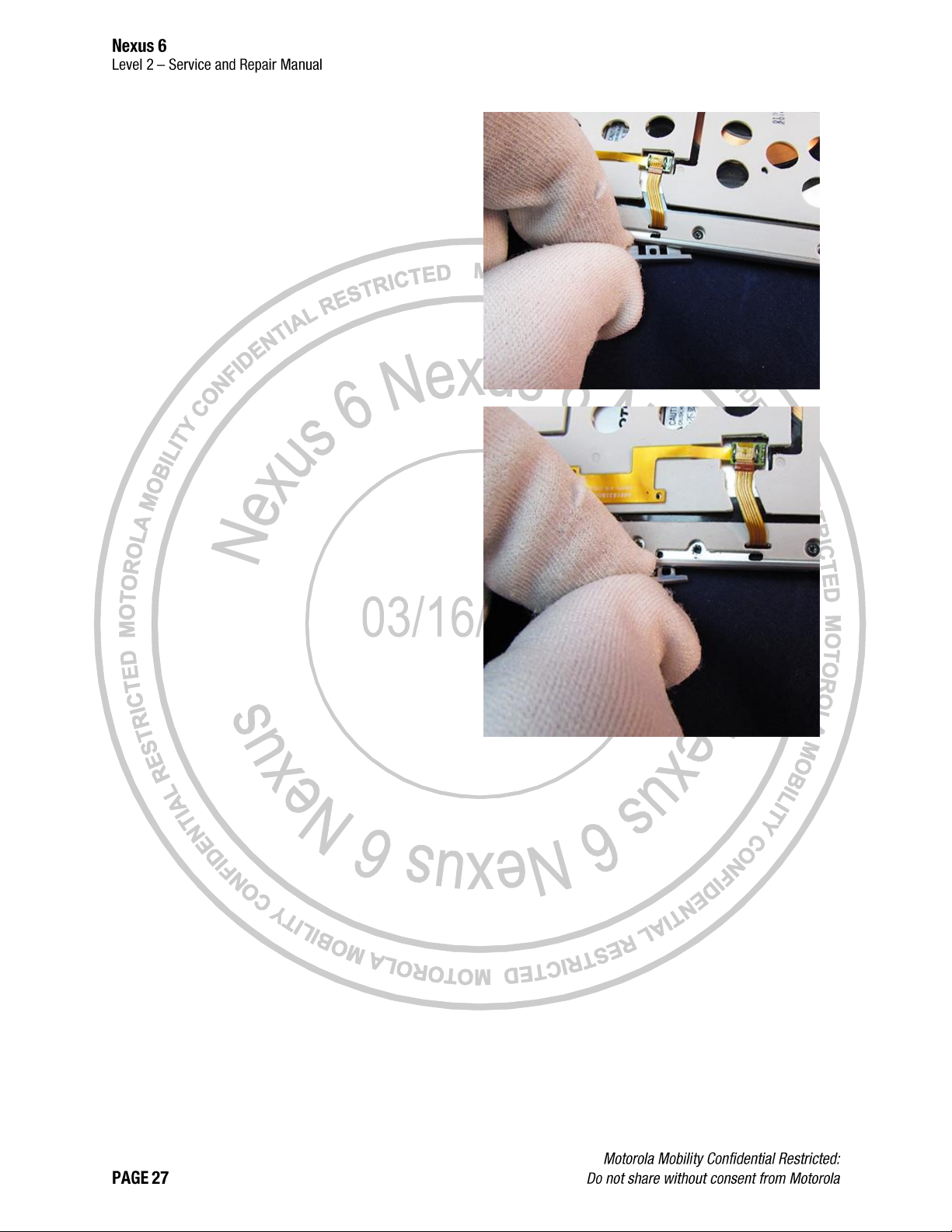
3. Remove the Power and Volume Keys. If they
stick in the housing, use the Tweezers and
Blackstick to pry them free.
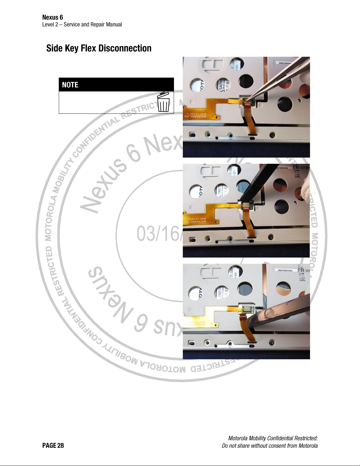
1. Remove the Kapton® Tape from the Side Key
Flex ZIF Connector.
After you remove the Kapton Tape, you
cannot reuse it.
2. Open the Side Key Flex ZIF Connector Door.
3. Disconnect the Side Key Flex from the Side Key
Flex ZIF Connector.
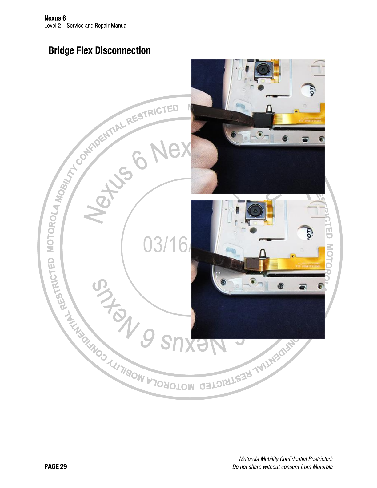
1. Remove the Bridge Flex Stopper using the
Blackstick or the Tweezers.
2. Use the flat end of the Blackstick to disconnect
the Bridge Flex Connector.
Failure to adhere to Safety Critical Note(s) may
increase risk of rupture, burning, or failure to
function safely when used by the customer. Refer
to the Battery Safety Guidelines.
Handle the Battery Pack with care. If dropped to the
floor, it may be internally damaged and must be
scrapped.
Ensure Battery and its insulation are not damaged (e.g.
scratched, dented, punctured) prior to and throughout
assembly.
Prior to assembly, ensure Battery edges and surfaces
are not dented or deformed, and that fixtures and parts
that will contact the Battery are free of foreign material.
Ensure screws and screwdrivers do not contact the
Battery.
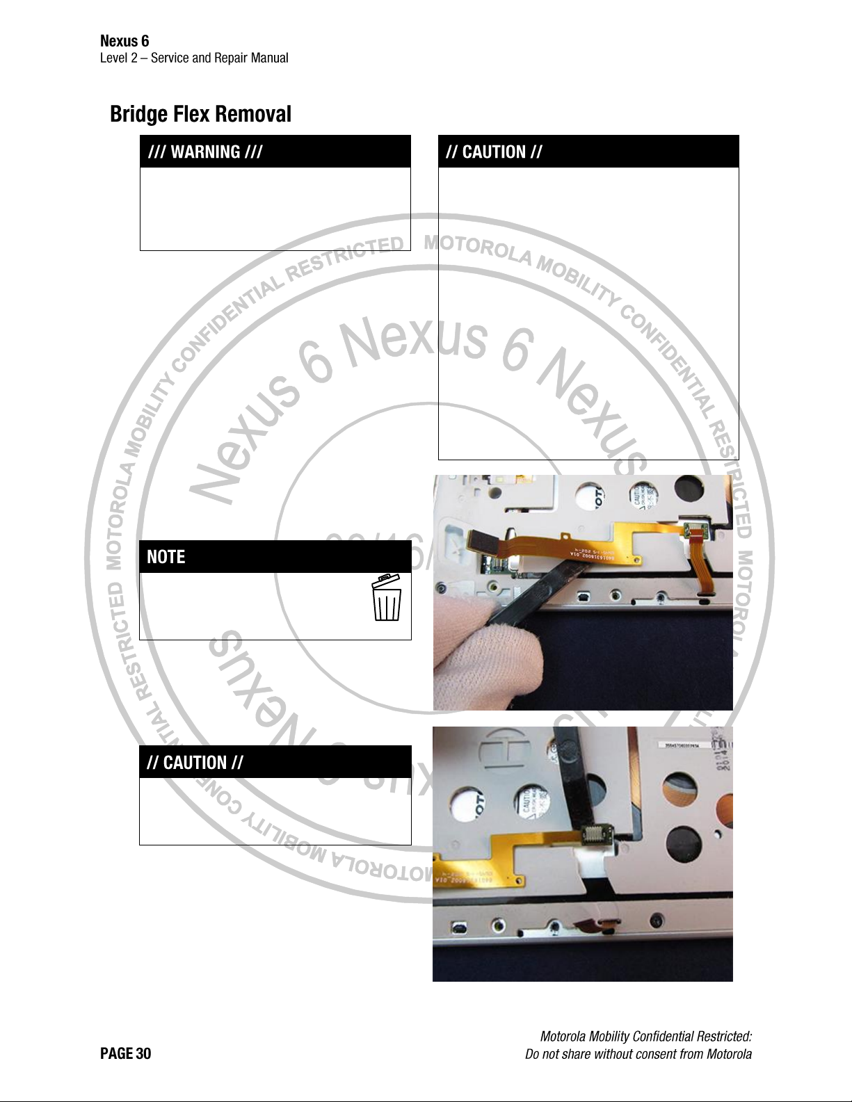
Use the Blackstick to lift and separate the
adhesive between the Bridge Flex, the Battery
surface, and the Rear Housing.
Remove the Bridge Flex only if
necessary. After you remove the Bridge
Flex, you cannot reuse it.
Do not use sharp tools or the pointed end of the
Blackstick to separate the Bridge Flex from the
Battery. Damage to the Battery may occur.
 Loading...