

Motorola MURP20040CT Datasheet
g() g g
F
gg
R
m
yp y ( ) g
RR
yp y g
RM
p
SEMICONDUCTOR TECHNICAL DATA
Order this document
by MURP20040CT/D
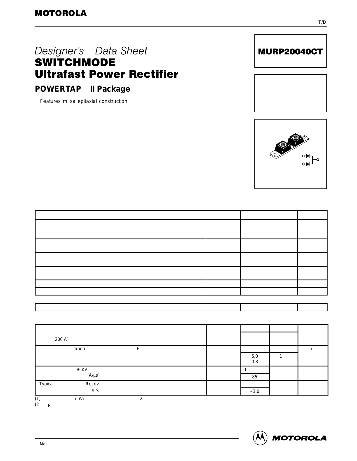
POWERTAP II Package
Features mesa epitaxial construction with glass passivation. Ideally suited
high frequency switching power supplies; free wheeling diodes and polarity
protection diodes.
• Stable, High Temperature, Glass Passivated Junction
• Monolithic Dual Die Construction. May be Paralleled for High Current
Output
Mechanical Characteristics:
• Case: Molded Epoxy with Metal Heatsink Base
• Weight: 80 grams (approximately)
• Finish: All External Surfaces Corrosion Resistant
• Base Plate Torques: See procedure given in the Package Outline Section
• Shipped 25 units per tray
• Marking: URP20040CT
MAXIMUM RATINGS
Rating Symbol Value Unit
Peak Repetitive Reverse Voltage
Working Peak Reverse Voltage
DC Blocking Voltage
Average Rectified Forward Current Per Leg
(At Rated VR, TC = 115°C) Per Package
Peak Repetitive Forward Current Per Leg
(At Rated VR, Square Wave, 20 kHz, TC = 115°C)
Non-Repetitive Peak Surge Current Per Package
(Surge applied at rated load conditions, halfwave, single phase, 60 Hz)
Storage/Operating Case Temperature T
Operating Junction Temperature T
THERMAL CHARACTERISTICS
Thermal Resistance — Junction–to–Case Per Leg R
V
RRM
V
RWM
V
R
I
O
I
FRM
I
FSM
stg, TC
J
tjc
ULTRAFAST
RECTIFIER
200 AMPERES
1
2
CASE 357C–03
POWERTAP II
400 Volts
100
200
200 Amps
800 Amps
–55 to +150 °C
–55 to +175 °C
0.5 °C/W
Amps
3
ELECTRICAL CHARACTERISTICS
Maximum Instantaneous Forward Voltage (1), see Figure 2 Per Leg
(IF = 100 A)
(IF = 200 A)
Maximum Instantaneous Reverse Current, see Figure 4 Per Leg
(VR = 400 V)
(VR = 200 V)
Typical Reverse Recovery Time (2) Per Leg
(IF = 1.0 A, di/dt = 50 A/ms)
Typical Peak Reverse Recovery Current Per Leg
(IF = 1.0 A, di/dt = 50 A/ms)
(1) Pulse Test: Pulse Width ≤ 250 µs, Duty Cycle ≤ 2%.
(2) TRR measured projecting from 25% of IRM to ground.
POWERT AP and SWITCHMODE are trademarks of Motorola, Inc.
This document contains information on a product under development. Motorola reserves the right to change or discontinue this product without notice.
Motorola Ultrafast Power Rectifier Data
Motorola, Inc. 1995
T
I
V
I
R
RR
RM
F
TJ = 25°C TJ = 100°C
1.3
1.5
TJ = 25°C TJ = 100°C
5.0
0.8
TJ = 25°C
85
TJ = 25°C
–3.0
1.2
1.4
193
61
Volts
m
A
ns
Amps
1
MURP20040CT
1E+3
1E+2
1E+1
TJ = 100°C
, INSTANTANEOUS FORWARD CURRENT (AMPS)
1E+0
F
I
VF, INSTANTANEOUS FORWARD VOLTAGE (VOLTS)
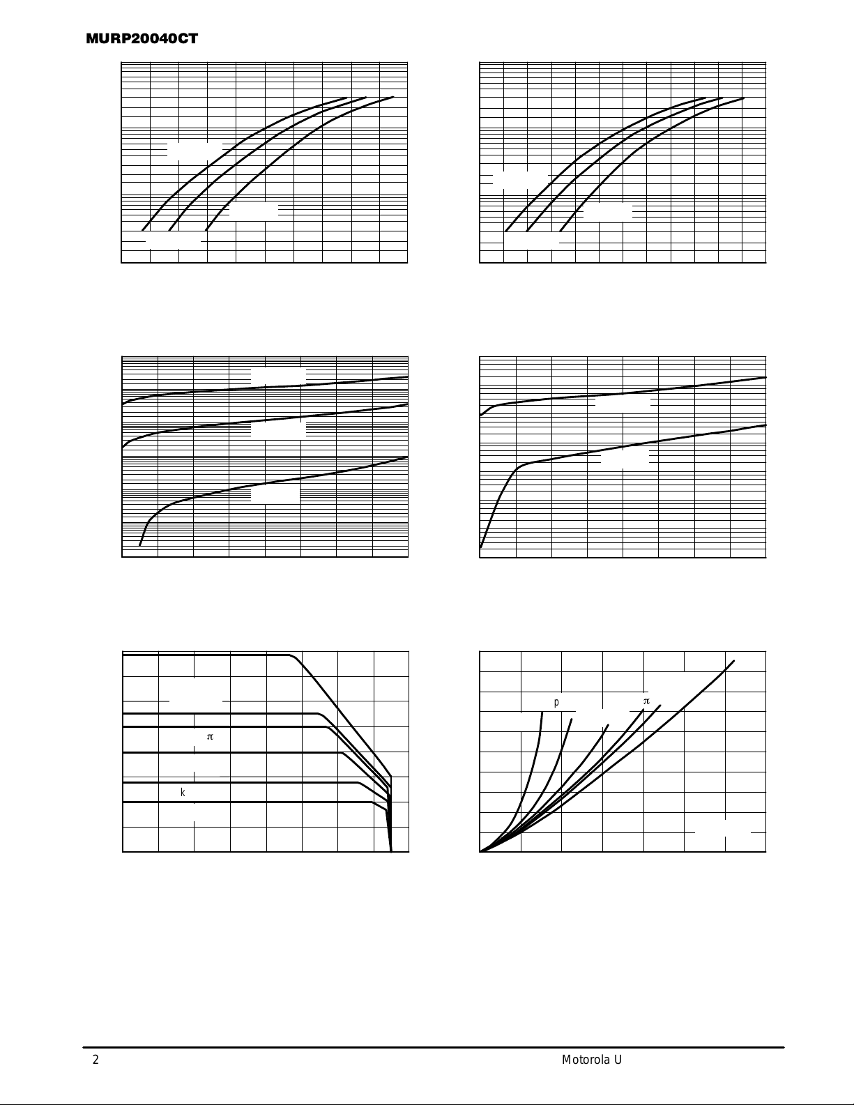
Figure 1. T ypical Forward Voltage Figure 2. Maximum Forward V oltage
1E–3
1E–4
1E–5
1E–6
1E–7
, REVERSE CURRENT (AMPS)
R
1E–8
I
1E–9
0 50 100 150
TJ = 175°C
TJ = 25°C
0.8 1.0
TJ = 175°C
TJ = 100°C
TJ = 25°C
200
VR, REVERSE VOLTAGE (VOLTS)
1.2
250 300 350 400
1.4 1.5 1.7
1E+3
1E+2
TJ = 175°C
1E+1
TJ = 100°C
, INSTANTANEOUS FORWARD CURRENT (AMPS)
1E+0
F
I
1E–2
1E–3
1E–4
1E–5
1E–6
1E–7
1E–8
, MAXIMUM REVERSE CURRENT (AMPS)
R
I
1E–9
0 50 100 150 200
0.70.5
VF, MAXIMUM INSTANTANEOUS FORWARD VOLTAGE (VOLTS)
VR, REVERSE VOLTAGE (VOLTS)
TJ = 25°C
1.31.10.90.60.4
TJ = 100°C
TJ = 25°C
250 300 350 400
160
140
120
100
80
60
40
20
, AVERAGE FORW ARD CURRENT (AMPS)
O
I
0
Figure 3. T ypical Reverse Current Figure 4. Maximum Reverse Current
SQUARE
WAVE
Ipk/Io =
Ipk/Io = 5
Ipk/Io = 10
Ipk/Io = 20
0
20 10040 60 80
Figure 5. Current Derating
dc
p
TC, CASE TEMPERATURE (
(PER LEG)
200
180
160
140
Ipk/Io = 20
120
100
80
60
40
, AVERAGE POWER DISSIPA TION (WATTS)
20
FO
P
0
140 160
120
°
C)
0
Ipk/Io = 10
25 125
IO, AVERAGE FORW ARD CURRENT (AMPS)
Ipk/Io =
Ipk/Io = 5
p
10050 75
SQUARE
WAVE
dc
TJ = 175°C
150 175
Figure 6. Forward Power Dissipation
(PER LEG)
2
Motorola Ultrafast Power Rectifier Data
 Loading...