

Motorola MUR6040 Datasheet
SEMICONDUCTOR TECHNICAL DATA
Order this document
by MUR6040/D
. . . designed for use in switching power supplies, inverters and as free
wheeling diodes, these state–of–the–art devices have the following features:
• Ultrafast 100 Nanosecond Recovery Time
• 175°C Operating Junction Temperature
• High Voltage Capability to 400 Volts
• Low Forward Voltage Drop
• High Temperature Glass Passivated Junction
Mechanical Characteristics:
• Case: Epoxy, Molded
• Weight: 4.3 grams (approximately)
• Finish: All External Surfaces Corrosion Resistant and Terminal Leads are
Readily Solderable
• Lead Temperature for Soldering Purposes: 260°C Max. for 10 Seconds
• Shipped 30 Units Per Plastic Tube
• Marking: U6040
1
3
MAXIMUM RATINGS
Rating Symbol Max Unit
Peak Repetitive Reverse Voltage
Working Peak Reverse Voltage
DC Blocking Voltage
Average Rectified Forward Current
TC = 70°C
Peak Repetitive Forward Current
(Rated VR, Square Wave, 20 kHz) TC = 150°C
Non Repetitive Peak Surge Current
(Surge applied at rated load conditions halfwave, single phase, 60 Hz)
Operating Junction Temperature and Storage Temperature TJ, T
THERMAL CHARACTERISTICS
Thermal Resistance, Junction to Case R
ELECTRICAL CHARACTERISTICS
Instantaneous Forward Voltage (1)
@ IF = 60 Amps, TC = 100°C
@ IF = 60 Amps, TC = 25°C
Instantaneous Reverse Current (1)
@ Rated dc Voltage, TC = 100°C
@ Rated dc Voltage, TC = 25°C
Reverse Recovery Time
IF = 1.0 Amp, dI/dt = 15 Amp/µs
(1) Pulse Test: Pulse Width = 300 µs, Duty Cycle ≤ 2.0%
V
RRM
V
RWM
V
I
F(AV)
I
FRM
I
FSM
θJC
V
I
t
RR
Motorola Preferred Device
ULTRAFAST RECTIFIERS
60 AMPERES
400 VOL TS
4
1
4
R
stg
F
R
–65 to +175 °C
3
CASE 340E–02, STYLE 1
400 Volts
60 Amps
60 Amps
600 Amps
0.8 °C/W
1.4
1.5
10
60
100 ns
Volts
mA
µA
SWITCHMODE is a trademark of Motorola Inc.
Preferred devices are Motorola recommended choices for future use and best overall value.
Rev 3
Motorola, Inc. 1996
1Rectifier Device Data
MUR6040
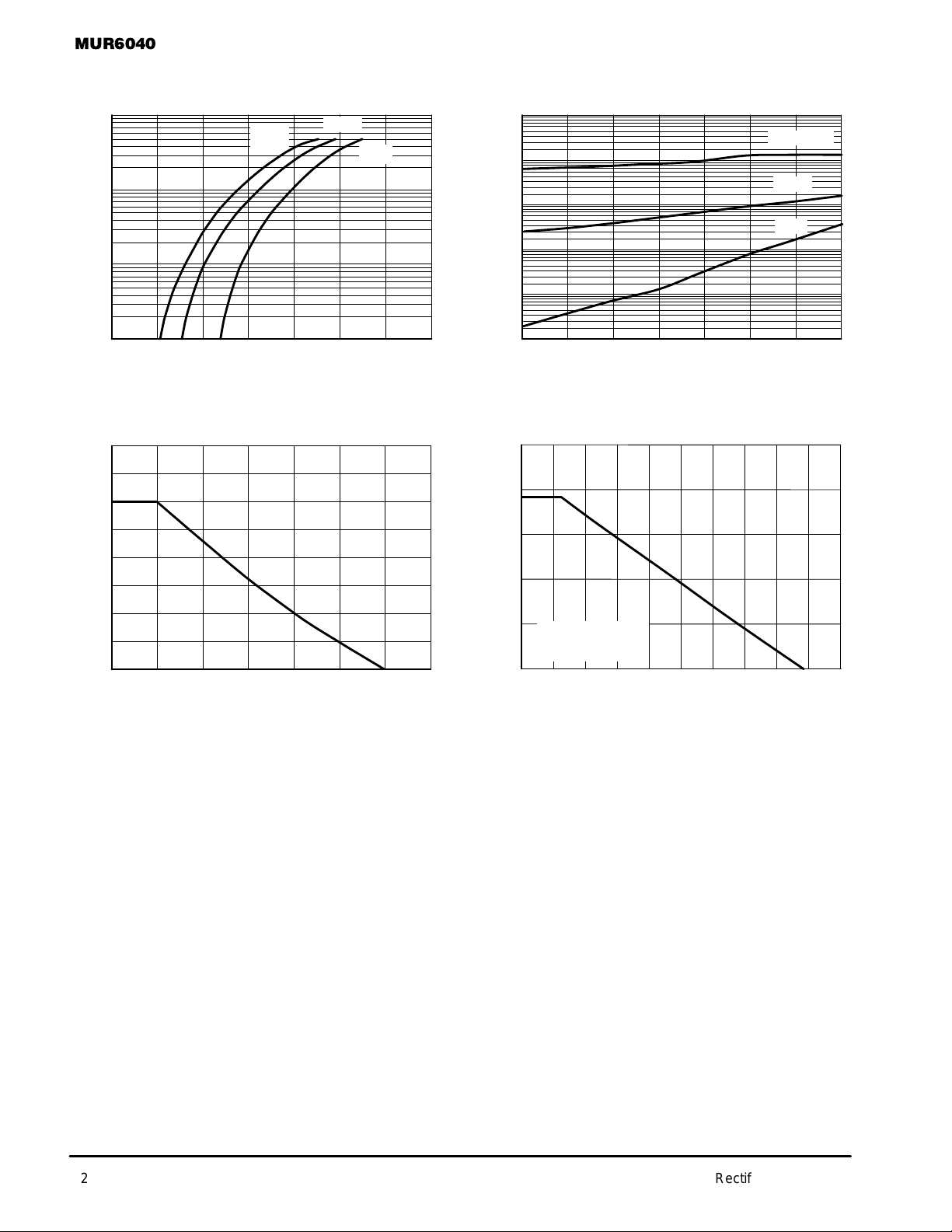
TYPICAL ELECTRICAL CHARACTERISTICS
100
10
1
, FORWARD CURRENT (AMPS)
F
i
0.1
°
C
150
VF, INSTANTANEOUS FORWARD VOLTAGE (mV)
100
°
C
25
°
C
1.51.31.10.90.70.50.30.1
Figure 1. T ypical Forward Voltage Figure 2. T ypical Reverse Current
80 5
70
60
50
40
30
20
, FORWARD CURRENT (AMPS)
F
i
10
0
120
140 160 175
TC, CASE TEMPERATURE (°C)
dc
Figure 3. Current Derating, Case Figure 4. Current Derating, Ambient
1000
100
µ
10
1
, REVERSE CURRENT ( AMPS)
0.1
R
I
0.01
50 100 200 300 350 400
4
3
2
, FORWARD CURRENT (AMPS)
F
1
i
WITH NO HEATSINK
0
20 40 60 80 100 200
0
150 250
VR, REVERSE VOLTAGE (VOLTS)
dc
IN FREE AIR
120 140 160 180
TA, AMBIENT TEMPERATURE (°C)
TJ = 150°C
100°C
25°C
2 Rectifier Device Data
 Loading...