

Page 1

68P81074C50-J
© 1996 by Motorola, Inc., Radio Products Group
8000 W. Sunrise Blvd., Ft. Lauderdale, FL 33322
Printed in U.S.A. 11/96. All Rights Reserved.
RSS Technical Support (Domestic): 800-367-4803 (Menu #5)
(International): 305-475-3778
MT 2000TM, MTS 2000TM,
MTX 838TM, MTX 8000TM,
and MTX 9000
TM
(MTSX)
Radio Service Software
User’s Guide
Software Part Number: RVN-4097
Page 2

LIST OF FIGURES ......................................................................................................................................................................
iv
LIST OF TABLES ........................................................................................................................................................................
iv
SECTION 1. INTRODUCTION
1.1 INTRODUCING THE MT 2000, MTS 2000, MTX 838, MTX 8000, AND
MTX 9000 (MTSX) RADIO SERVICE SOFTWARE
........................................................................................................
1-1
1.2 PREREQUISITES..........................................................................................................................................................1-2
1.3 USING THIS MANUAL ..................................................................................................................................................1-3
SECTION 2. GETTING STARTED AND INITIAL SETUP
2.1 ASSEMBLING THE HARDWARE .................................................................................................................................2-1
2.2 UNDERSTANDING COMPUTER BASICS....................................................................................................................2-4
2.2.1 Identifying Major Computer Parts ....................................................................................................................2-6
2.2.1.1 Monitor...............................................................................................................................................2-6
2.2.1.2 System Unit .......................................................................................................................................2-6
2.2.1.3 Keyboard ...........................................................................................................................................2-6
2.3 UNDERSTANDING COMPUTER STORAGE SYSTEMS .............................................................................................2-7
2.3.1 Random Access Memory (RAM) .....................................................................................................................2-7
2.3.2 Read Only Memory (ROM)..............................................................................................................................2-7
2.3.3 Hard-Disk Drive................................................................................................................................................2-7
2.3.4 Diskettes..........................................................................................................................................................2-7
2.4 UNDERSTANDING THE DISK OPERATING SYSTEM (DOS).....................................................................................2-8
2.5 WHAT'S ON THE RSS DISKETTES ...........................................................................................................................2-11
2.6 ORGANIZING YOUR HARD DISK AND DISKETTES.................................................................................................2-12
2.6.1 Organizing Your Hard Disk............................................................................................................................2-13
2.6.2 Organizing Your Archive File Diskette...........................................................................................................2-14
2.7 STARTING THE RSS ..................................................................................................................................................2-15
2.7.1 Making a Backup Copy of RSS Diskette(s) ...................................................................................................2-15
2.7.2 What To Do with Previous Versions of RSS Diskettes ..................................................................................2-16
2.7.3 Starting the RSS From the Hard Disk............................................................................................................2-16
2.7.4 Installing the RSS on Your Hard Disk............................................................................................................2-16
2.7.5 Installing the RSS on Multiple Computers or Networks.................................................................................2-17
2.7.6 Hard Disk RSS Startup Procedure.................................................................................................................2-17
2.7.7 The Banner Screen........................................................................................................................................2-18
2.7.8 The Main Menu..............................................................................................................................................2-19
2.8 NAVIGATING THROUGH THE RSS MENUS.............................................................................................................2-19
2.8.1 The Keyboard Keys and Their Functions.......................................................................................................2-20
2.8.2 Anatomy of a Menu........................................................................................................................................2-22
2.8.3 Anatomy of a Screen .....................................................................................................................................2-23
2.8.4 A Complete Menu Mapping at a Glance........................................................................................................2-24
2.8.5 The Relationship Between Screens...............................................................................................................2-27
2.9 CHANGING A FIELD VALUE ......................................................................................................................................2-28
68P81074C50
i
MT 2000TM, MTS 2000TM,
MTX 838TM, MTX 8000TM,
and MTX 9000
TM
(MTSX)
Radio Service Software
User’s Guide
Software Part Number: RVN-4097L
TABLE OF CONTENTS
, Motorola, MT 2000, MTX 838, MTX 8000, MTX 9000, MTS 2000, Single Tone, SmartZone, HearClear,
Quik-Call, Quik-Call II,and Private-Line are trademarks of Motorola, Inc.
© 1993,1994,1996 by Motorola, Inc., Radio Products Group
8000 W. Sunrise Blvd., Ft. Lauderdale, FL 33322
Printed in U.S.A. 06/95. All Rights Reserved.
Page 3

2.10 SETTING (CONFIGURING) THE RSS COMPUTER DEFAULTS ..............................................................................2-29
2.10.1 Setting Default Archive and Backup Paths....................................................................................................2-30
2.10.2 Setting a Communications Port....................................................................................................................2-31
2.11 EXITING THE RSS......................................................................................................................................................2-32
2.12 MAIN MENU .................................................................................................................................................................2-33
2.12.1 How to Read the Codeplug............................................................................................................................2-35
2.12.1.1 Reading the Codeplug...................................................................................................................................2-35
2.12.1.2 Reading Codeplug Data from the Radio........................................................................................................2-35
2.12.1.3 Reading Disk Codeplug Files.........................................................................................................................2-35
2.13 SETUP CONFIGURATION..........................................................................................................................................2-36
2.13.1 Configuring Paths and Port............................................................................................................................2-37
2.13.2 Setting Screen Colors....................................................................................................................................2-39
SECTION 3. BASIC RADIO PROGRAMMING TUTORIAL
3.1 INTRODUCTION TO SECTION.................................................................................................................3-1
3.2 PROGRAMMING A BASIC MT2000 CONVENTIONAL RADIO................................................................3-2
3.2.1 Desired Features...........................................................................................................................3-2
3.2.2 Major Decisions Involved ..............................................................................................................3-2
3.2.3 High Level Programming Flow......................................................................................................3-2
3.2.4 Step-by-Step Specific Programming Instructions..........................................................................3-2
3.2.5 MT2000 Button/Switch/Menu Item Defaults..................................................................................3-4
3.2.6 Read Current Radio's Personality (Codeplug) ..............................................................................3-6
3.2.7 Program the Radio Wide Features First........................................................................................3-6
3.2.8 Program the Phone List.................................................................................................................3-7
3.2.9 Programming Conventional Personalties......................................................................................3-7
3.2.10 Program the Zone/Channel Features Next ...................................................................................3-9
3.2.11 Fill in the Scan List......................................................................................................................3-10
3.2.12 Program the Personality Into the Codeplug ................................................................................3-11
3.2.13 Program the Personality Into Archive and Backup Files.............................................................3-12
3.3 PROGRAMMING A BASIC MTX8000 TRUNKED RADIO.......................................................................3-13
3.3.1 Desired Features.........................................................................................................................3-13
3.3.2 Major Decisions Involved ............................................................................................................3-13
3.3.3 High Level Programming Flow....................................................................................................3-13
3.3.4 Step-by-Step Specific Programming Instructions........................................................................3-13
3.3.5 MTX8000/9000 Radio Button/Switch/Menu Item Defaults..........................................................3-15
3.3.6 Read Current Radio's Personality (Codeplug) ............................................................................3-17
3.3.7 TCMS Merge Process.................................................................................................................3-17
3.3.8 Program the Radio Wide Features First......................................................................................3-17
3.3.9 Steps to Assign Controls.............................................................................................................3-18
3.3.10 Program the Phone List...............................................................................................................3-20
3.3.11 Program a Talkgroup Scan with One List....................................................................................3-20
3.3.12 Steps to Modify Personalities......................................................................................................3-21
3.3.13 Program the Zone/Channel Features Next .................................................................................3-22
3.3.14 Steps to Fill in the Scan List........................................................................................................3-23
3.3.15 Program Data into Radio Codeplug ............................................................................................3-24
3.3.16 Exit the RSS................................................................................................................................3-25
3.4 CLONING MORE RADIOS THE SAME WAY..........................................................................................3-25
3.4.1 Desired Features.........................................................................................................................3-25
3.4.2 Major Decisions Involved ............................................................................................................3-25
3.4.3 Step-by-Step Specific Programming Instructions........................................................................3-25
3.4.4 Read Desired Source Archive File..............................................................................................3-26
3.4.5 Clone Current Radio From Archive File ......................................................................................3-26
3.4.6 Cloning Remaining Radios..........................................................................................................3-27
3.4.7 Cloning Additional Radios...........................................................................................................3-28
TABLE OF CONTENTS (Cont.) MTSX RSS
ii
68P81074C50
Page 4

3.4.8 Exit the RSS................................................................................................................................3-28
3.5 ADDITIONAL RADIO MODELS...............................................................................................................3-29
3.5.1 MTS 2000 Radio Button/Switch/Menu Item Default....................................................................3-30
SECTION 4. SERVICE MENU FUNCTIONS
4.1 RADIO SERVICE VIA RSS MANUAL............................................................................................................................4-1
4.2 SERVICE MENU............................................................................................................................................................4-1
4.2.1 Transmitter Alignment Menu..............................................................................................................................4-3
4.2.1.1 Reference Oscillator Alignment...........................................................................................................4-5
4.2.1.2 Transmit Power Alignment ..................................................................................................................4-6
4.2.1.3 Transmit Deviation Balance (Compensation) Alignment.....................................................................4-8
4.2.1.4 Transmit Deviation Limit Alignment...................................................................................................4-10
4.2.1.5 Transmit Deviation Limit Alignment: Reference Softpot....................................................................4-11
4.2.1.6 Transmit VCO Crossover Alignment .................................................................................................4-12
4.2.1.7 Secure Transmit Deviation................................................................................................................4-13
4.2.2 Receiver Alignment Menu................................................................................................................................4-14
4.2.2.1 Front End Filter Alignment.................................................................................................................4-16
4.2.2.2. Rated Audio Alignment......................................................................................................................4-17
4.2.2.3 Squelch Attenuator (12.5kHz) Alignment ..........................................................................................4-18
4.2.2.4 Squelch Attenuator (20kHz) Alignment .............................................................................................4-19
4.2.2.5 Squelch Attenuator (25/30kHz) Alignment ........................................................................................4-20
4.2.2.6 Receive VCO Crossover Alignment..................................................................................................4-21
4.2.2.7 Secure Receive Discriminator Level .................................................................................................4-22
4.2.3 Signalling Alignment Menu ..............................................................................................................................4-23
4.2.3.1 DTMF Transmit Deviation .................................................................................................................4-24
4.2.3.2 Transmit Signalling: High Speed.......................................................................................................4-26
4.2.3.3 Transmit Signalling: MDC 1200.........................................................................................................4-27
SECTION 5. GET/SAVE/PROGRAM MENU FUNCTIONS
5.1 INTRODUCTION TO SECTION.....................................................................................................................................5-1
5.2 GET/SAVE/PROGRAM MENU......................................................................................................................................5-1
5.2.1 Reading Codeplug Data.....................................................................................................................................5-3
5.2.1.1 Reading Codeplug Data From the Radio ............................................................................................5-3
5.2.1.2 Reading Codeplug Data From an Archive File....................................................................................5-4
5.2.2 Get TCMS Ccodeplug update disk file ..............................................................................................................5-6
6.2.2 Radio Cloning ...........................................................................................................................................5-7
5.2.4 Saving Codeplug data to an archive file ..........................................................................................................5-10
5.2.5 Programming the Radio’s Codeplug................................................................................................................5-12
5.2.6 Programming History .......................................................................................................................................5-13
SECTION 6. CHANGE/VIEW MENU FUNCTIONS
6.1 INTRODUCTION TO SECTION.....................................................................................................................................6-1
6.2 CHANGE VIEW MENU..................................................................................................................................................6-1
6.2.1 Radio Wide Configuration Menu........................................................................................................................6-3
6.2.1.1. Radio Wide Options ............................................................................................................................6-4
6.2.1.1.1 Radio Wide Secure Options ..............................................................................................6-8
6.2.1.1.2 Radio Wide Emergency Options......................................................................................6-10
6.2.1.1.3 More Radio Wide Options................................................................................................6-12
6.2.1.2 Radio Wide Features Configuration Menu ........................................................................................6-14
6.2.1.2.1 Radio Wide Button Configuration ....................................................................................6-15
6.2.1.2.2 Radio Wide Switch Configuration ....................................................................................6-18
6.2.1.2.3 Radio Wide Menu Item Configuration..............................................................................6-20
6.2.1.3 Phone Configuration..........................................................................................................................6-23
6.2.1.3.1 DTMF Access/Deaccess Codes......................................................................................6-25
6.2.1.3.2 Dial Options ....................................................................................................................6-27
MTSX RSS TABLE OF CONTENTS (cont.)
68P81074C50
iii
Page 5

MTSX RSS TABLE OF CONTENTS (cont.)
6.2.1.4 Radio Wide Scan Lists And Options.................................................................................................6-29
6.2.1.4.1Radio Wide Scan Options................................................................................................6-32
6.2.1.5 Radio Wide Display Options..............................................................................................................6-35
6.2.2.5.1Radio Wide Display More Options...................................................................................6-38
6.2.2 Trunking Menu.................................................................................................................................................6-40
6.2.2.1 Trunking Radio Wide Options...........................................................................................................6-40
6.2.2.1.1SmartZone Environment..................................................................................................6-42
6.2.2.1.2Voice on Control Options.................................................................................................6-46
6.2.2.2 Trunking Systems..............................................................................................................................6-48
6.2.2.2.1Channel Assignment Data...............................................................................................6-54
6.2.2.2.2Control Channel ..............................................................................................................6-56
6.2.2.3 Trunking System Options.................................................................................................................6-58
6.2.2.3.1 One Touch Button Options.................................................................................................6-61
6.2.2.3.2.Trunking Status Alias.........................................................................................................6-62
6.2.2.2.3 Trunking Message Alias.....................................................................................................6-63
6.2.2.4 Trunking Personality ......................................................................................................................6-64
6.2.2.4.1Trunking Subfleets...........................................................................................................6-70
6.2.2.4.2Trunking Talkgroup..........................................................................................................6-71
6.2.2.4.3Trunking Emergency Data Configuration.........................................................................6-73
6.2.2.4.4Trunking Personality Options...........................................................................................6-77
6.2.2.4.4.1SmartZone Preferred Sites...........................................................................6-79
6.2.2.5 Trunking Call List...............................................................................................................................6-81
6.2.3 Conventional Menu..........................................................................................................................................6-82
6.2.3.1 Conventional Radio Wide Options....................................................................................................6-85
6.2.3.2 Conventional Personality Using GE Star Signalling..........................................................................6-87
6.2.3.2.1Personality MDC Options................................................................................................6-93
6.2.3.2.2Conventional Personality Phone Options........................................................................6-96
6.2.3.2.3More Conventional Personality Options..........................................................................6-98
6.2.3.2.3.1 Conventional RAC Options.........................................................................6-102
6.2.3.3 MDC Configuration Menu................................................................................................................6-104
6.2.3.3.1 MDC Systems ...............................................................................................................6-105
6.2.3.3.2More Emergency Options .............................................................................................6-109
6.2.3.3.2.1 MDC System Options.................................................................................6-110
6.2.3.3.2.2 MDC System Remote Options....................................................................6-113
6.2.3.3.3 Call List Table.................................................................................................................6-115
6.2.3.4 Auxaliry Systems.............................................................................................................................6-117
6.2.3.4.1Singletone System.........................................................................................................6-119
6.2.3.4.2Singletone List...............................................................................................................6-121
6.2.3.4.3Quik-Call II System........................................................................................................6-122
6.2.3.4.4GE Star System.............................................................................................................6-125
6.2.3.4.5Conventional Message Alias List...................................................................................6-128
6.2.3.4.6Conventional Status Alias List.......................................................................................6-130
6.2.4 Zone/TalkGroup (Channel) Assignment........................................................................................................6-132
SECTION 7. PRINT MENU FUNCTIONS
7.1 INTRODUCTION TO SECTION....................................................................................................................................7-1
7.1.1 Print Radio Wide Features Configuration Menu..............................................................................................7-3
7.1.2 Trunking Menu.................................................................................................................................................7-4
7.1.3 Conventional Menu..........................................................................................................................................7-5
SECTION 8. FILE MAINTENANCE MENU FUNCTIONS
8.1 INTRODUCTION TO SECTION....................................................................................................................................8-1
8.2 FILE MAINTENANCE MENU.........................................................................................................................................8-1
8.2.1 Create Directory Path......................................................................................................................................8-3
8.2.2 Delete Archive File...........................................................................................................................................8-4
iv
68P81074C50
Page 6

SECTION 9. FLASHPORT UPGRADE
9.1 INTRODUCTION TO FLASHPORT...............................................................................................................................9-1
9.2 FLASHING PROCEDURE.............................................................................................................................................9-1
9.3 FLASHING UPGRADE ..................................................................................................................................................9-2
APPENDIX A Computer to Radio Communications Error Codes.........................................................................A-1
APPENDIX B TPL Frequencies and Codes Table...............................................................................................B-1
APPENDIX C MTSX Features..............................................................................................................................C-1
APPENDIX D Trunking Radio Personality Chart..................................................................................................D-1
APPENDIX E Conventional Radio Personality Chart............................................................................................E-1
KEY MENU INDEX.......................................................................................................................................INDEX-1
GLOSSARY..........................................................................................................................................................G-1
MTSX RSS TABLE OF CONTENTS (cont.)
v
68P81074C50
Page 7

LIST OF TABLES
1-1 Types of RSS Programmable Features and Functions ............................................................................1-1
2-1 Step to Connect Hardware........................................................................................................................2-3
2-2 Installation Tone Identification ..................................................................................................................2-3
2-3 Some DOS Commands............................................................................................................................2-9
2-4 Special DOS Command Characters.......................................................................................................2-10
2-5 RSS Diskette(s) Contents.......................................................................................................................2-11
2-6 Steps to Create a Hard Disk Directory Tree ...........................................................................................2-15
2-7 Steps to Backup the RSS Diskette(s).....................................................................................................2-16
2-8 RSS Hard Disk Installation Procedure....................................................................................................2-18
2-9 Hard Disk Startup Procedures................................................................................................................2-19
2-10 Creating Archive File Paths ....................................................................................................................2-32
2-11 Setting a Port..........................................................................................................................................2-33
3-1 Quick Steps to Bring Up MAIN MENU......................................................................................................3-1
3-2 Conventional Radio Personality Chart......................................................................................................3-3
3-3 MT2000 Radio Button / Switch / Menu Item Defaults...............................................................................3-4
3-4 Steps to Read A Radio's Personality (Codeplug) .....................................................................................3-6
3-5 Steps to Program Radio-Wide Features...................................................................................................3-6
3-6 Steps to Create a Phone List....................................................................................................................3-7
3-7 Steps to Program Conventional Personalties...........................................................................................3-8
3-8 Steps to Program Zone/Channel Features...............................................................................................3-9
3-9 Steps to Create a Scan List....................................................................................................................3-10
3-10 Steps to Save Personality to Radio's Codeplug......................................................................................3-11
3-11 Steps to Save Radio Personality to Archive and Backup Files...............................................................3-12
3-12 Trunked Radio Personality Chart............................................................................................................3-14
3-13 MTX8000/9000 Radio Button / Switch / Menu Item Defaults..................................................................3-15
3-14 Steps to Read a Radio's Personality (Codeplug)....................................................................................3-17
3-15 Steps to Merge/Download TCMS ...........................................................................................................3-17
3-16 Steps to Assign Button and Switch Functions ........................................................................................3-18
3-17 Steps to Program the Phone List............................................................................................................3-19
3-18 Steps to Program Talkgroup Scan with One Lis.....................................................................................3-20
3-19 Steps to Modify Personalities for Scan and Phone.................................................................................3-21
3-20 Steps to Program Zone/Channel Features.............................................................................................3-22
3-21 Steps to Fill in the Scan List....................................................................................................................3-23
3-22 Steps to Save Personality to Radio's Codeplug......................................................................................3-24
3-23 Steps to Exit the RSS .............................................................................................................................3-25
3-24 Steps to Clone Radios............................................................................................................................3-27
3-25 Cloning Additional Radios.......................................................................................................................3-28
3-26 Steps to Exit the RSS .............................................................................................................................3-28
3-27 MTS2000 Radio Button/Switch/Menu Item Defaults...............................................................................3-29
3-28 MTS2000 Radio Button/Switch/Menu Item Defaults...............................................................................3-30
TABLE OF CONTENTS (cont.) MTSX RSS
68P81074C50 vi
Page 8

LIST OF FIGURES
2-1 Equipment Setup....................................................................................................................................................2-1
2-2 Hard Disk Directory Tree ......................................................................................................................................2-13
2-3 Diskette Directory Tree.........................................................................................................................................2-14
2-4 The Banner Screen...............................................................................................................................................2-20
2-5 The Main Menu.....................................................................................................................................................2-21
2-6 The Computer Keyboard ......................................................................................................................................2-21
2-7 An RSS Menu.......................................................................................................................................................2-24
2-8 An RSS Screen.....................................................................................................................................................2-25
2-9 RSS Menu Mapping at a Glance ..........................................................................................................................2-27
2-10 Relationship Between Screens.............................................................................................................................2-29
2-11 Changing a Field Value ........................................................................................................................................2-30
2-12 Service Software Configuration Menu Options.....................................................................................................2-31
3-1 Button Locator Diagram (Button Location Purposes Only).....................................................................................3-5
3-2 Button Locator Diagram (Button Location Purposes Only)...................................................................................3-16
MTSX RSS TABLE OF CONTENTS (cont.)
vii 68P81074C50
Page 9

NOTES
MTSX RSS
viii 68P81074C50
Page 10
SECTION 1. INTRODUCTION
Welcome to the world of two-way radio programming from Motorola's Radio Products Group.
1.1 INTRODUCING THE MT 2000™, MTS 2000™, MTX 838™, MTX 8000™, AND MTX 9000™ (MTSX)
RADIO SERVICE SOFTWARE
This Radio Service Software (RSS) manual is targeted for anyone who wants to program features into the
MT 2000, MTS 2000, MTX 838, MTX 8000, and MTX 9000 radios or align a radio. This feature programming, or
customizing, personalizes a radio for the needs of individual customers, resulting in radios with unique
personalities.
This series of portable radios has a unique set of features, including unique PL/DPL codes for each channel, a
variety of signalling abilities with channel scan, and the convenience of maintenance-free tuning, due to the
wideband capability.
This feature set makes these radios ideal for commercial businesses and police and fire protection services that
typically utilize radios in their vehicles.
So how can Motorola design radios with such a wide range of features and still offer a variety of radio services
with the ability to customize and personalize radios? The answer is embedded in modern microprocessor chip
technology in the radio and the development of the MTSX RSS - a computer program that, when interfaced with a
radio, electronically programs and personalizes a radio with a unique set of features for each individual customer.
No tools are needed. This RSS computer program resides on the diskettes you received in the package with this
manual (package RVN4097I).
Here are just some of the features and functions available using the RSS.
MTSX RSS INTRODUCTION
68P81074C50 1-1
Table 1-1. Types of RSS Programmable Features and Functions
MTSX RSS Programmable Features MTSX RSS Service Functions
Transmit (Tx) frequencies
Receive (Rx) frequencies
PL/DPL codes
Signalling system parameters
Scan lists and scan options
FLASHport Upgrade (requires FLASHport
upgrade package)
Reference oscillator alignment
Transmit deviation alignment
Transmit power alignment
Replaced power amplifier calibration
Replaced logic board calibration
Replaced RF board calibration
This radio’s customization and servicing is accomplished by using an IBM®Personal System/2®model 30 or
higher computer.
NOTE
We recommend you test any computer’s RSS compatibility before purchasing by taking the computer to your shop,
connecting all the hardware, installing the software, starting the RSS and reading and writing data to and from a
radio. If problems occur, call the phone number on the front cover for help - do this prior to purchasing your
computer.
Page 11

1.2 PREREQUISITES
To use the RSS to program the radios, we recommend a basic working knowledge of the following:
1. Microcomputers.
2. MS-DOS operating system, version 5.0 or later.
This application requires:
80386 or 80486
DOS 5.0 or later
4 Megabytes of RAM or greater.
The powerful features and extensive flexibility of these new radio families require much more codeplug data
validation than in the past. For complex configurations, it is recommended that the RSS be executed from a RAM
disk. This will reduce execution time significantly (an order of magnitude).
3. The radio’s available features (see the appropriate radio Operator's Manual).
4. Your customers’ needs.
For computer beginners, we’ll teach some computer and MS-DOS basics. However, this manual is written for
both beginners and advanced users, so the primary prerequisite for using the RSS is the desire to program and
deliver an excellent radio to a ready customer.
1.3 INTRODUCTION OF NEW RELEASE
This release of the MTSX RSS utilizes the extended memory capability of the 386 and 486 PCs. To take
advantage of these performance enhancements your machine must be a 386 or 486 based machine with 4M of
memory (1M lower + 3M or more extended). This application is compatible with DOS 6.0, but cannot be run as a
Double Space file.
With extended memory, the application will now run with less than 100K of conventional memory available!
Resident programs and TSR (Terminate & Stay Resident) utilities no longer have to be disabled. This has also
permitted the installation procedure to be significantly improved and simplified. The CONFIG.SYS modifications
required to run the application have been automated, and are described in the rest of this introduction.
A new Tutorial section (Chapter 3) has been added to the manual to discuss programming requirements of some
of the specific MT2000, MTX8000, MTX9000, and MTS2000 models. This release added support for Secure
MTS2000 radio models, and also corrected some defects of the previous release.
1.3.1 EXTENDED MEMORY OPERATION
Previous versions of this application recommended the usage of extended memory for a RAMDrive to reduce the
disk I/O access time. (The application however, only used conventional memory for actual execution.) This
version does not
require the use of a RAMDrive or a SMARTDrive.
INTRODUCTION MTSX RSS
1-2 68P81074C50
Page 12

The new install program will determine if your system has an adequate amount of memory available (3M) and a
286, 386 (or 486) CPU for extended memory operation. If present, the RSS will be installed.
The following line should be added to the CONFIG.SYS file if necessary:
device = c:\dos\HIMEM.SYS
device =c: \dos\EMM386.EXE OFF
Files = 30
NOTE
The DOS MEM command may be used to determine the amount of available
memory in your machine (i.e. type c:\dos\mem. The location of MEM.EXE may
differ on your machine.) If the command reports 3000K or more of available
extended memory, you can take full advantage of these enhancements.
1.4 SUBSCRIPTION INFORMATION
Your RSS is part of a subscription. We’ll keep you advised of changes and automatically mail revisions
throughout the life of the subscription.
A subscription is good for one site. Under the terms of your subscription, you may install the RSS on as many
personal computers as desired at that one site. Another site location requires another subscription.
1.5 USING THIS MANUAL
This manual is designed to teach basic feature programming and to speed up access to technical reference
information. It is intended for both beginners and advanced users of computers and the RSS. This manual
describes how to connect the radio to your computer and how to install the software. The operation of the
software is described, including how to read the screens, the keyboard commands, and how the screens are
organized.
The MAIN MENU and all available RSS functions are described in detail. The operation of the SERVICE
functions, the GETTING and SAVING of radio codeplug data, and the CHANGING and VIEWING of codeplug
data are described also.
All RSS function screens are depicted in this manual and the operation of each one is described. A description of
each data field is also given.
The GLOSSARY defines terms and abbreviations used within this manual.
The INDEX provides a quick way of locating particular items.
NOTES, CAUTIONS, and WARNINGS are used throughout this manual. The following definitions apply to the
these statements,
NOTE
An operating procedure or condition which is essential to highlight.
CAUTION
An operating procedure or practice which, if not strictly observed, might result in damage or
destruction of equipment.
WARNING
AN OPERATING PROCEDURE OR PRACTICE WHICH MIGHT RESULT IN PERSONAL INJURY OR
LOSS OF LIFE IF NOT CORRECTLY FOLLOWED.
MTSX RSS INTRODUCTION
68P81074C50 1-3
Page 13

NOTES
INTRODUCTION MTSX RSS
1-4 68P81074C50
Page 14
Introductions accomplished, it’s time to get started. In the GETTING STARTED subsection we’ll guide you
through identifying, installing and learning the necessary hardware and software to run the RSS, which will be
used to service and program a radio. In the GETTING STARTED subsection, we’ll also familiarize you with the
computer, the keyboard, and the RSS menus, screens, and fields. The INITIAL SETUP subsection prepares you
for SECTION 2 through SECTION 8, which describe how to service and program a radio, and maintain your radio
service files.
2.1 ASSEMBLING THE HARDWARE
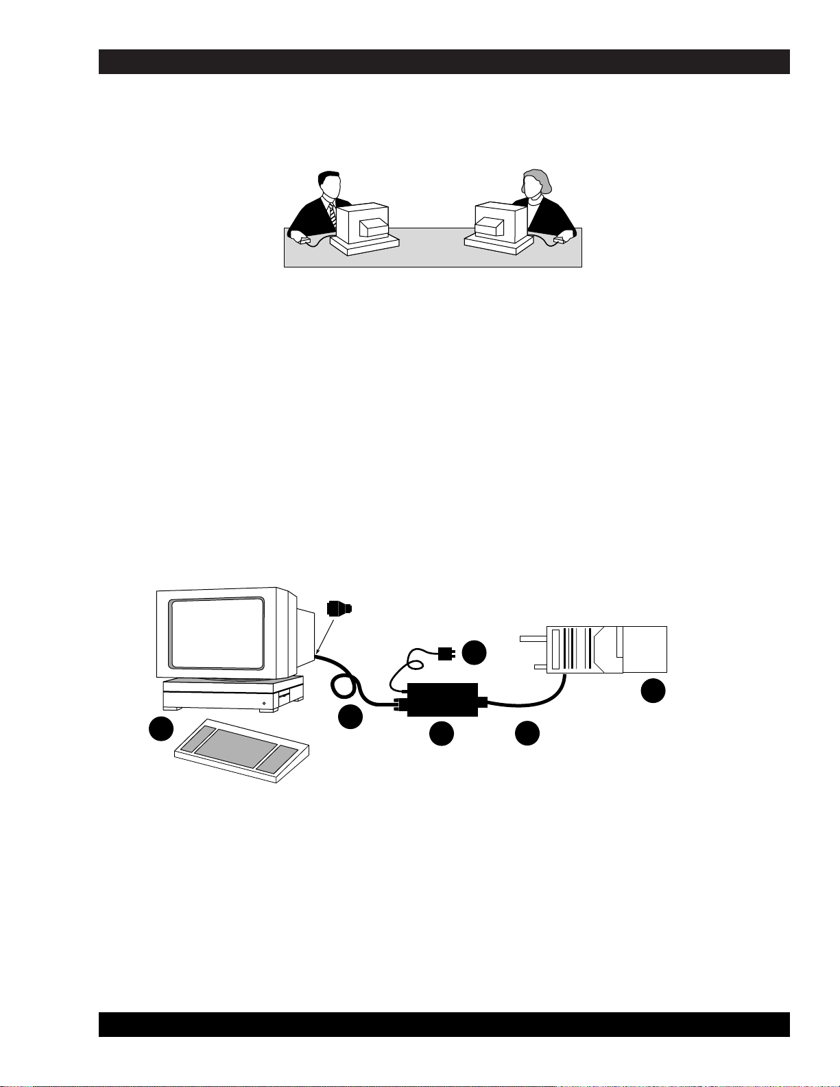
The figure below shows the required and optional equipment to program a radio. The computer recommended is
an IBM®Personal System/2®model 30 or higher computer, with 640K of RAM, one diskette drive, and one hard
disk drive.
MTSX RSS GETTING STARTED
68P81074C50 2-1
Figure 2-1. Equipment Setup
SECTION 2. GETTING STARTED AND INITIAL SETUP
D
F
E
C
B
A
MAEPF-22704-O
Page 15
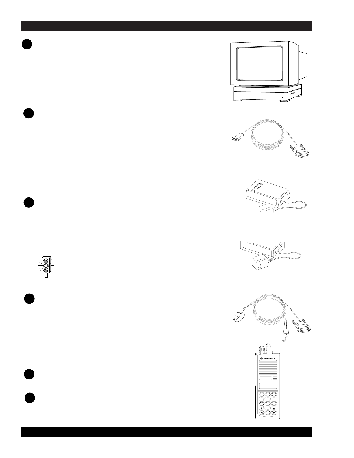
Computer
An IBM®Personal Computer XTTM(or compatible) may be used, but
we recommend as a minimum a 386 based computer is required to
improve throughput (a 80386 based computer or higher is preferred),
or
IBM®Personal System/2®(model 30 or higher)
Computer should have 640k of RAM, one
diskette drive, and one hard drive; computer
should run DOS 5.0.
Radio Interface Box (RIB) to Computer Cable
30-80369B72 cable for IBM®Personal Computer AT
®
or compatible computer (9-pin end and a 15-pin end)
or
30-80369B71 cable for computers requiring a 25-pin serial
port connection (25-pin end and a 15-pin end)
Smart Radio Interface Box (SRIB) to Computer Cable
30-80390B49 cable for IBM®Personal Computer AT
®
or compatible computer (9-pin end and a 15-pin end)
See Appendix A for connection details.
Radio Interface Box (RIB)
RLN4008B RIB
For laptop computer and on-the-road use only;
omit item D below and use a 9V battery (not included).
or
Smart Radio Interface Box (SRIB) for FLASHport Only
RLN1015A RIB (required for FLASHport upgrade)
CAUTION: Use a fresh, 9V battery. LED remains lit with a
weak battery - this may cause certain errors on screen.
RIB Power Supply
01-80357A57 (110 Vac) Power Supply
or
01-80358A56 (220 Vac) Power Supply
SRIB Power Supply
01-80302E27 (120 Vac) Power Supply
For FLASHport Only
Using the power supply is more reliable
than using a weak battery.
RIB-to-Radio Cable
RKN4035A Cable
Radio
MT 2000, MTS 2000, MTX 838, MTX 8000
or
MTX 9000 Portable Radio.
GETTING STARTED MTSX RSS
2-2 68P81074C50
MT 2000
HOME
2
ABC
1
3
DEF
6
MNO
5
JKL
4
GHI
7
PRS
8
TUV
9
WXY
0
A
B
C
D
E
F
Page 16
You can install, start or explore the RSS using just the diskettes and your computer if you don’t have all the
hardware. You can even update existing radio archive files stored on disk. What you cannot do without the
hardware is read from or save to an actual radio.
CAUTION: When programming or calibrating a radio , DO NOT disconnect the radio from the
RIB when the computer is communicating with the radio - it may leave the radio in an
inoperable state. The only recommended time to disconnect the radio is at the MAIN MENU or
GET/SAVE/PROGRAM screens.
NOTE
If you are using a laptop computer and you plan to use the RSS while the computer is in battery mode, you
may need to set the serial/parallel adapter to run on battery power. This can be done with the application
diskette supplied by the computer manufacturer. If this is not done, you will receive serial bus errors.
NOTE
If your RIB has a switch and LED, be sure to turn on the switch before each programming session.
MTSX RSS GETTING STARTED
68P81074C50 2-3
Table 2-1. Steps to Connect Hardware
Steps to Connect the Hardware
After you connect the hardware, turn on the radio by turning the volume control clockwise. You will hear one of
the following types of tones.
This tone ..... Means this....
1. Connect A and C with B. First, plug the
9-pin end of B into the communications port
of A. Then connect the 15-pin end to C.
If your computer has a 25-pin connections
port connector, you will need the cable 3080369B71 to insert between A and B.
2. Connect F and C with E. The 25-pin end of E goes into C,
and the modular telephone connector end plugs into the side
connector on the front of F.
3. Plug D into the wall outlet, and connect the other end to C.
Higher-pitched, short tone
Continuous, low tone
Hardware is connected correctly and the radio's internal firmware
is operating correctly. Note: This tone may be disabled in the
codeplug and may not be heard.
Critical failure - a radio's internal software malfunction.
Table 2-2. Installation Tone Identification
Page 17

GETTING STARTED MTSX RSS
2-4 68P81074C50
2.2 UNDERSTANDING COMPUTER BASICS
If you are already familiar with computers, skip this section and proceed to “STARTING THE RSS” section.
Your computer can be compared to both an electronics technician and a file cabinet. A file cabinet provides easy
handling, storage, and retrieval of written data. Your computer provides the same. The technician can, with tools,
manually and physically alter the radio’s features and functionality. Similarly, the computer provides the same
with the RSS - a radio dealer or employee can give a radio unique features, save those features for future
reference, copy, or service a radio internally. This can all be achieved without opening a drawer, thumbing
through papers, picking up a tool, or disassembling the radio.
Let’s learn some of the types of computers used for programming radios, the major parts of a computer, and the
ways and places to store your desired radio personality data.
The RSS is designed to run on the following IBM computers and their compatibles: IBM Personal Computer AT,
and IBM Personal System/2 model 30 and higher.
The RSS is not a Windows or OS/2 program. You must not have Windows or OS/2 loaded or the RSS
program will not operate correctly.
Page 18

MTSX RSS GETTING STARTED
68P81074C50 2-5
2.2.1 Identifying Major Computer Parts
Computers range in complexity and size from ones that easily and lightly fit on your lap to ones the size of a car
that require air-conditioned, smoke and dust-free environments. Falling between this range is the microcomputer,
which is common in many households and businesses today. Whatever their size, most microcomputers
(hereafter referred to as computers) consist of a monitor, a system unit, and a keyboard.
2.2.1.1 Monitor
Monitors perform like a window into the computer, allowing us to see on a display the data inside the computer.
Monitors come in a variety of sizes and colors. Some can be bigger than a 19-inch diagonal television, though a
common size is 12 inches diagonally. Monochrome monitors have only one color behind the words and pictures
on the display, which in many cases is either green, amber, white or black. Color monitors can display two or
more colors on the display at a time, but with color monitors a slight decrease in picture sharpness or text
legibility may be experienced. Colors on the RSS screen can be selected or changed by the user by using the
RSS. To help users quickly find their place on the display before typing, a flashing underscore, called a cursor,
typically serves as a visual place indicator.
Besides the display, a monitor usually has a power cord, an on/off switch, brightness and contrast dials, and a
cable connection to the system unit.
The RSS can function with either monochrome, CGA, EGA or VGA-based monitors.
2.2.1.2 System Unit
The system unit contains a special chip that is the brain of the computer, one or more diskette drives, a hard-disk
drive, a cable connection to the keyboard, one or more communications ports and an on/off switch. The system
unit should be treated with care, as jarring and hot temperatures could internally damage the unit.
2.2.1.3 Keyboard
A user instructs the computer what to do by typing commands on the keyboard. The display shows the
commands as they are typed. Most keyboards have letter keys, numeric keys, and a number of special keys that
perform special functions. The “NAVIGATING THROUGH THE RSS MENU” section describes some of these
special keys and how they perform with the RSS.
2.3 UNDERSTANDING COMPUTER STORAGE SYSTEMS
The computer can store amazing amounts of data (software programs, code, data, files) in several places. Some
of these places are:
• the random-access memory (RAM),
• the read-only memory (ROM),
• the hard-disk drives, and
• the diskettes
The RAM, ROM, hard disks and diskettes all vary in function and all have certain size limits (memory). They all
store data in terms of bytes, a byte equalling approximately one character as typed on the keyboard. 1,024 bytes
equals one kilobyte, or 1K. For comparison purposes, one page of double-spaced, typed text equals
approximately 2K.
Page 19

GETTING STARTED MTSX RSS
2-6 68P81074C50
2.3.1 Random Access Memory (RAM)
Random Access Memory (RAM) is a storage place in the system unit used to run programs and operating
systems. The amount of RAM varies from computer to computer, and it directly affects which programs will run on
your computer. With more RAM you can run larger programs. Most programs indicate how much RAM is required
to run the RSS. You must have at least 200k of free RAM to execute this RSS.
2.3.2 Read Only Memory (ROM)
Read Only Memory (ROM) is a storage place in the system unit that is used by the computer for start-up, booting
and Power-On Self-Test (POST) purposes. The ROM is “read-only,” which means a user cannot write or save
data to it, over it, delete it, or in any other way destroy it by using the keyboard keys. The program in the ROM is
hard-coded into the ROM chip, and as such is protected from user errors.
2.3.3 Hard-Disk Drive
The hard-disk drive stores a user’s programs and files (data). The data can originate from data the user
generates at the keyboard, or from data that is copied from a diskette in a diskette drive, explained below. The
memory capacity of hard-disk drives varies from computer to computer and can be increased with the purchase
and installation of a memory upgrade. Many hard-disk drives can store 20 megabytes (20MB = 20 million bytes),
30MB, or more than 40MB of data. Most hard disks are labeled as the “C” drive.
2.3.4 Diskettes
Diskettes also store users’ programs and files but are different from hard disks because of their transportable,
small size and packaging. A diskette must be “formatted” before storing your files and programs on it. After a
diskette is inserted into a diskette drive, data on the magnetic diskette can be retrieved, stored, manipulated or
erased.
Diskettes come in 3-1/2 inch and 5-1/4 inch sizes, and their memory capacity varies from 360K (low density) to
1.44MB (high density). The RSS is distributed to you on a 3-1/2” low density diskette and two 5-1/4” low density
diskettes so that it may be easily loaded onto any appropriate computer, regardless of the type of diskette drive
that is available. Handle the diskettes carefully - avoid contact with the shiny, brown, magnetic disk surface under
the protective plastic cover on the 5-1/4” diskette and the magnetic disk surface under the sliding metal plate on
the 3-1/2” diskette. Such contact could damage the data or make it unreadable by the drive.
Page 20

MTSX RSS GETTING STARTED
68P81074C50 2-7
Diskette drives come in two sizes; one to accommodate the 5-1/4” diskettes. With the 5-1/4” diskette drives, after
a diskette is inserted as far as it will gently go, you must close or push down the “drive door” located on the
outside of the drive or else the computer will not read the data on the diskette. This drive door generally swings
down and locks into place when firmly pressed, and it releases when gently pressed back the other direction
when you want to remove your diskette.
Most diskette drives are labeled “A” or “B,” “A” generally being the topmost (or highest) one. The drives are
labeled by the computer dealer before delivery to the customer.
Instructions, steps, tables and procedures that apply to computers with only diskette drives (no hard disk drive)
will be displayed in a shaded box.
NOTE
To learn more about computer basics, read “The Personal Computer Book” by Peter McWilliams, Prelude Press, Los
Angeles, CA. Call 1-800-LIFE-101 to order or secure further information.
2.4 UNDERSTANDING THE DISK OPERATING SYSTEM (DOS)
• A computer user operates, communicates with and commands the computer using the computer’s Disk
Operating System (DOS). The DOS commands have special meanings to the computer.
• Before you can use DOS commands, they must be installed on your hard disk.
• MS-DOS version 5.0 or later is required to run the RSS.
• DOS commands can be entered either in upper case or lower case letters. This manual shows shows all
DOS commands in upper case letters.
• Next is a table of DOS commands that you may use now or in the future for RSS work. Words in italics
mean you should substitute that word for the word that is appropriate for your specific situation.
Page 21

Table 2-3. Some DOS Commands
DOS Command What it means...
A: Go to drive “A.”
B: Go to drive “B.”
C: Go to drive “C.”
CD\ Return to the Root Directory. CHDIR is the same as CD.
CD
DIRNAME
Change directory to the directory named “dirname.” Maximum directory length is 8 characters.
cd used alone will display the current working path name.
COPY B:*.* A: Makes an identical copy of all files. The *.* means all files within the directory specified. You
can also copy files in the same directory giving the file a different name as the second argument
to copy command, and you can combine several files into one file or append files. In all cases,
the first argument is the source file (the one to copy from) and the last argument is the target file
(the one to copy to).
DEL Filename Deletes the filename in the current directory
DEL *.* CAUTION: Files cannot be recovered after executing this command. Delete all files in
current directory
DIR Lists the files in the current working directory. You can list files in other directories also by
specifying a path name following the command. If you have more files than will fit on the
display, you can type DIR/P, which will make DOS pause when the display is full. Pressing any
key resumes the listing. DIR/W specifies a wide display (5 columns) of file names.
DISKCOPY B: A: Copies the contents of the disk in drive B to the disk in drive A. Drives must be of the same size
and density. If your drives are not the same size and density, use the same drive name twice,
such as DISKCOPY A: A:.
FORMAT A: Format an unused, new or old diskette in drive A of the computer so it will accept MS-DOS files.
MD
DIRNAME
Makes a new subdirectory called “dirname” of 8 characters or less. You substitute your
directory name for the italicized word dirname. MKDIR is the same as MD.
PROMPT $P $G Change the display's prompt to include the current working directory's drive and path name,
followed by the “>” sign. This sign is typically seen in the AUTOEXEC.BAT file.
PATH Set a command search path (such as PATH=C:\MRSS\MTSX\ARCHIVE). This tells the
computer to search this directory after the working directory when a command is entered. This
sign is typically seen in the AUTOEXEC.BAT file.
RD DIRNAME Remove a subdirectory called “dirname”. Removal of the subdirectory requires that it be empty.
Files can be deleted by the DEL command. RMDIR is the same as RD.
VER Prints MS-DOS version installed on the computer, such as MS-DOS Version 5.0.
XCOPY Copies files and directories, including all subdirectories. This command uses disk space more
efficiently and can speed up file access time.
For further information on these and other commands, consult your MS-DOS User’s Manual.
GETTING STARTED MTSX RSS
2-8 68P81074C50
Page 22

MTSX RSS GETTING STARTED
68P81074C50 2-9
You may have noticed some special characters in the preceding table (*). Certain keyboard characters mean
special things to DOS. Some of these are:
Special DOS Character What it means...
*
Wildcard character. You can substitute this character for any type or
quantity of characters/digits that follow (not precede) it.
\
Backslash. A special character to separate directories
when specifying path names. By itself, it also represents the root
directory.
?
Wildcard character meaning you can substitute/match it for any
single-digit or character.
/
Front slash. Used for setting options of commands.
Table 2-4. Special DOS Command Characters
There are a couple limitations you may want to know about DOS, RSS files, and directories.
1) First, DOS only allows file names to be 8 characters long. However, file names can have an optional
1, 2 or 3-character extension after the file name. The extension must be separated from the file name
by a period (sometimes called a dot).
2) Second, DOS allows only 111 files under the root directory (topmost) on any diskette or hard disk. We
highly recommend that you further subdivide your files into more directories before you accumulate
this many files in any directory, not just the root directory. It’s very confusing and time-consuming to
work with or view this many files at once.
3) Last, the maximum number of files allowed by the RSS in any non-root directory, whether diskette or
hard disk, is approximately 400. This is an RSS limitation, not a DOS or computer limitation. If you
have more than 400 files, create another directory.
The RSS is not a Microsoft Windows program. The RSS can be executed only from the DOS prompt on
computers which are not running Microsoft Windows.
Page 23

GETTING STARTED MTSX RSS
2-10 68P81074C50
2.5 WHAT’S ON THE RSS DISKETTES
Below are the files located on the diskettes you received with this manual.
File Name File Type Description
These files are in the top ROOT directory
DISK #1
INSTALL.EXE installation file
INSTALL.DAT installation file
MTSXINS.001 executable files
DISK.ID installation file
DISK #2
DISK.ID installation file
MTSXINS.002 executable files
RSS Installation program. Change to the floppy drive &
type install to begin.
Installation Data
This is a compressed version of the file that the install
program uncompresses during installation to your hard
disk.
Installation Data
Installation Data
This is a compressed version of the file that the install
program uncompresses during installation to your hard
disk.
A file can be a program (a set of commands to tell the computer what to do), or a collection of data or information.
As mentioned in the DOS section, DOS files generally have two parts - a file name followed by a file extension,
which is optional. The extension provides an easy way to, at a glance, identify or tag files for easy grouping or
categorizing. In the computer world, some file extension naming conventions have evolved, and Motorola uses
these conventions in the RSS, as you may have noticed.
Now you know what’s on the RSS diskettes we supply. Next you’ll learn how to organize your own disk and
diskettes that you’ll use to store your radio archive files. We suggest that frequent RSS users and computer pros
skip the “ORGANIZING YOUR HARD DISK AND DISKETTES” section and join us back in the “STARTING THE
RSS” section. New users should read all sections.
Page 24

MTSX RSS GETTING STARTED
68P81074C50 2-11
2.6 ORGANIZING YOUR HARD DISK AND DISKETTES
When you first start using computers you typically do not have a lot of files to organize. But after a while it gets
increasingly difficult to distinguish between file types, to pick out a specific file in a long list, to keep track of
what’s in which file, or to remember which files are similar in content. Therefore, it’s important to spend some time
now deciding which types or groups of files should be located together in a common place, called a directory.
You can make directories using the DOS MD or MKDIR commands (or inside the RSS via the FILE
MAINTENANCE MENU).
You may want to organize your directories first by customer area, then by customer name, and finally by radio
model type, or perhaps in the reverse order. Consider the different ways in which you operate your business - do
you separate radio files by customer location, by sales revenue, by fiscal year, or perhaps by date of purchase?
When deciding how to organize your files and directories, we suggest a few things:
• First, we advise you to put as few directories as possible near the top, or root, of your directory tree,
considering your future growth too. (For example, if you have 100 customers within 4 geographical
areas, we suggest your first level of sub directories be the areas that encompass the customer. The next
level of directories would be the
customer names
within each of those areas.) The idea is to make the
root system spread out wider the deeper you grow, similar to a pyramid shape.
• Keep the RSS diskette contents in one directory and your archive files in a different directory.
• Keep archive files in separate directories according to radio model type (MT, MTX, MTS, etc). It is not
possible to know a file’s model type by looking at the file name. Have a separate directory name for each
radio model, then store the archive files for that specific model within the appropriate model directory.
This way archive files for multiple model types are not located in the same directory.
• The last point we recommend is to dedicate and create a separate diskette for your backup files;
always
make backup copies of your files
. If you routinely store archive files on your hard disk, make backup
copies of your files on a diskette.
Page 25
GETTING STARTED MTSX RSS
2-12 68P81074C50
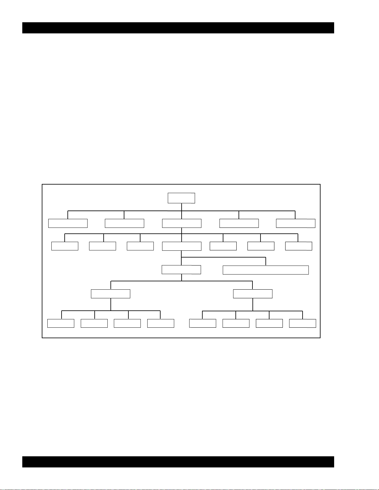
2.6.1 Organizing Your Hard Disk
Below is a sample directory tree for storing your radio archive files on your computer’s hard disk. Though your
hard disk directory tree may be a little different based upon your way of doing business, this setup may be a
starting point for you. The install program will automatically create the MRSS and MTSX directories for you if they
do not exist.
We suggest that you execute the following command before starting. If you place it in your autoexec.bat file, it will
be executed every time the computer is started. PROMPT $P$G. The prompt will the show your current location
in the directory tree. Note how the prompt changes when the following commands are typed to change
directories. The prompt is shown in bold face.
C> prompt $P$G
C:\> CD\mrss
C:\mrss\>
Figure 2-2. Hard Disk Directory Tree
ROOT
SPREAD SHEET WP
MRSS
DATA BASE GRAPHICS
Etc.SPECTRA STX VISARPP SABER SI MTSXEtc.
ARCHIVE
EXECUTABLE PROGRAM FILES
1993
FIRE
SECURITY
TOWING COURIER
1994
FIRE
SECURITY TOWING COURIER
Page 26
MTSX RSS GETTING STARTED
68P81074C50 2-13
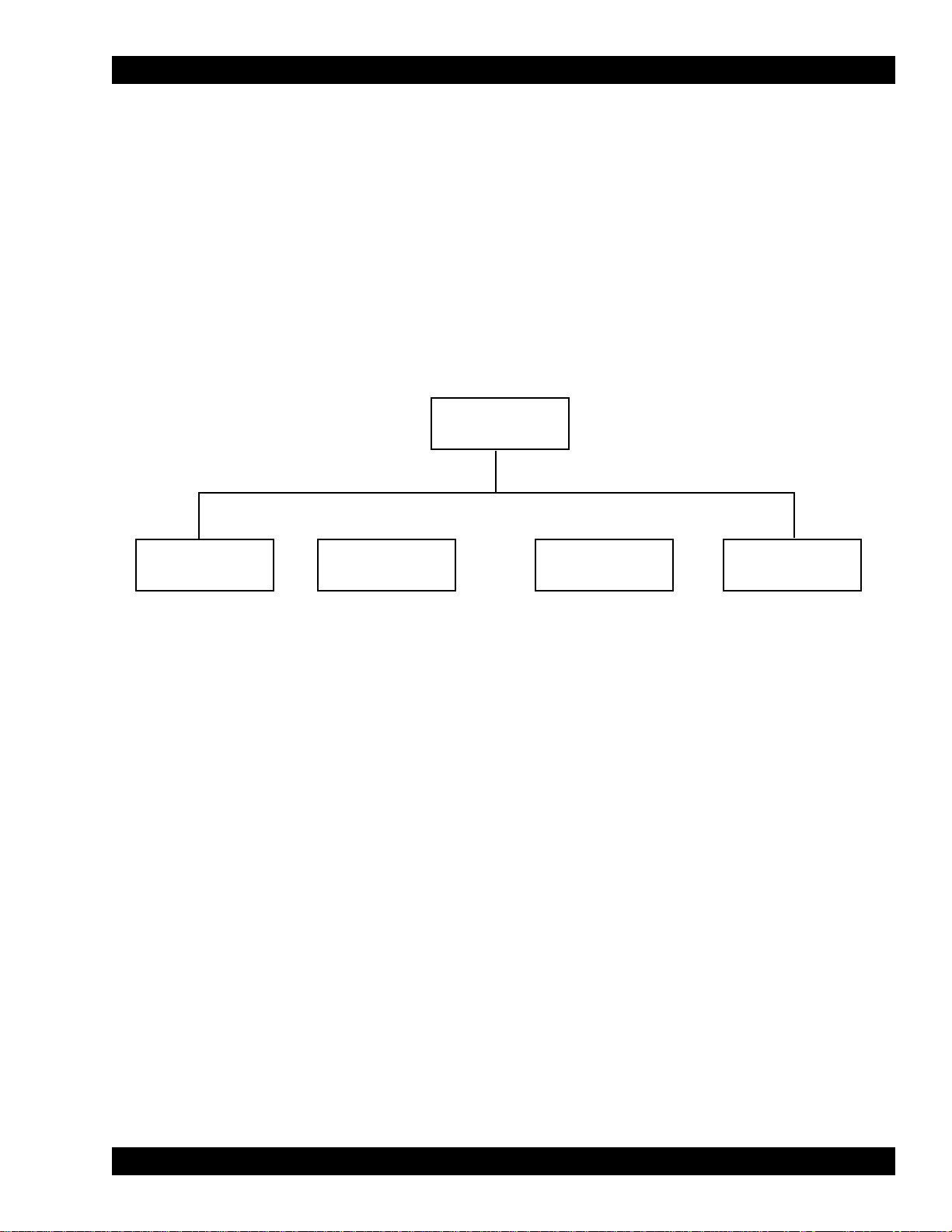
2.6.2 Organizing Your Archive File Diskettes
Below is a sample diskette directory tree for storing your radio archive files on a diskette.
Organizing a diskette is easier due to smaller space on a diskette. Though your tree may be different based upon
your way of doing business, this set-up may be a starting point for you. Be sure to label your diskettes accurately,
such as “1993 MTSX Archive Files”. Depending on the size of your business, you may even have a separate
diskette for FIRE, one for SECURITY, etc.
To create the directory tree shown in Figure 2-3 on your diskette, follow the steps on table 2-6. After each
command, press Return or Enter. This exercise assumes you are using drive A and the diskette contains only
MTSX archive files (not RSS files and not backup files).
Figure 2-3. Diskette Directory Tree
ROOT
FIRE
SECURITY TOWING COURIER
Page 27

GETTING STARTED MTSX RSS
2-14 68P81074C50
Table 2-6. Steps to Create Diskette Directory Tree
Instruction What to Type Explanation
1. Create diskette label
2. If no hard disk, load DOS
3. Put new diskette in A
4. Format diskette
5. Label diskette
6. Insert diskette again
7. Start at root
8. Make FIRE directory
9. Make SECURITY directory
10. Make a TOWING directory
11. Make a COURIER directory
12. Create other directories
FORMAT A:
CD \
MD FIRE
MD SECURITY
MD TOWING
MD COURIER
Label formatted diskette to correspond to the
contents of the diskette such as “MTXS Archive
Files”. Don’t apply it to the diskette yet.
See Table 2-3 to load DOS using drive A. Remove
DOS diskettes after loading. If not at the root
directory of drive A, type: A:cd\
Insert a new diskette into A. Close the drive door.
Format the new diskette in drive A. Discard diskette
if errors occur.
Remove formatted diskette; apply label without
covering the exposed magnetic area.
Insert diskette into drive A again. Close door.
Move (change directory) to the root (uppermost)
directory of the diskette. Omit if already at root
level.
Make a directory under Root called “FIRE”.
Make a directory under Root called “SECURITY”.
Make a directory under Root called “TOWING”.
Make a directory under Root called “COURIER”.
Make more directories for each additional category
you may need.
Page 28

MTSX RSS GETTING STARTED
68P81074C50 2-15
2.7 STARTING THE RSS
You have accomplished a lot so far - you have identified and assembled the hardware, you acquired knowledge
of basic computer and DOS concepts, and how to organize disks. You are now ready to start the RSS on your
computer. This section, approximately 30 minutes long, will explain when to install, reinstall, or discard the RSS
diskettes. It will guide you through installation process of the RSS on a hard disk, and finally, it lists how to start
the RSS with the appropriate executable command.
2.7.1 Making a Backup Copy of RSS Diskette(s)
As with any program, it is important to make a backup copy of the RSS diskette before you begin to use it.
Whenever you receive a new version of the RSS, you should make a backup copy.
We recommend a backup copy of your RSS, even if you have a hard disk. To make a backup copy, follow the
steps below. These steps assume you have one diskette drive named A or you have two diskette drives that are
not the same size and density, and that DOS is loaded.
Note
DISKCOPY will not copy from one drive to another if the drives are not the exact same size and density.
1. Insert RSS diskette Put supplied RSS diskette into
drive A; close the door
2. Make the backup copy DISKCOPY A: A: This copies the data on the source
diskette in drive A (supplied RSS diskette) to the
target diskette (the newly formatted diskette).
Caution: accidentally reversing the insertion
order of the diskettes will erase the contents of
the RSS diskette. DOS will tell you when to insert
the source diskette (RSS one) and when to insert the
target diskette (the newly formatted one). When the
diskcopy is complete, use the target diskette as the
new working copy.
3. Keep originals safe Store the original RSS diskettes in
a safe place away from magnets, moisture, heat and
possible damage.
Instruction What to Type Explanation
Table 2-7. Steps to Backup the RSS Diskette(s)
Page 29

GETTING STARTED MTSX RSS
2-16 68P81074C50
2.7.2 What To Do with Previous Versions of RSS Diskettes
After you have created a backup copy of the new RSS diskettes, you may wonder what to do with the previous RSS
versions you may have accumulated. We recommend discarding the older versions so that you do not accidently
program the radio with outdated data.
2.7.3 Starting the RSS From the Hard Disk
A hard-disk drive installation program is on the RSS diskettes. After installing the RSS on your hard disk, follow the
startup procedure.
2.7.4 Installing the RSS on Your Hard Disk
Install the latest RSS version as soon as you receive it. Using the install program on the diskettes you received with
this manual assures that you have the latest and greatest version of the RSS. It also keeps important files in a
consistent place for cross-referencing and future use. The software installation takes approximately three minutes.
The install program will:
• Create the MRSS, MTSX and ARCHIVE directories, if they are not already there.
• Write over the old version’s program files with the same name, if present.
The install program will
not
:
• Write over your archive files.
Before doing the installation steps that follow, be sure you have made a backup copy of the RSS, explained in the
“Making a Backup Copy of RSS Diskette(s)” section and Table 2-7 “Steps to Backup the RSS Diskette(s).”
The steps below install the RSS on your computer. After each “What to Type” step below, press Return or Enter.
Instruction What to Type Explanation
Table 2-8. RSS Hard Disk Installation Procedure
1. Put RSS diskette in drive A.
2. Go to drive A. A:
3. Start the installation. INSTALL
4. Store diskettes in safe place
Insert the RSS Diskette into Drive A (close the
door), later you will be instructed to insert the
other one.
This tells the computer to work from drive A.
This transfers the RSS to your hard disk. Follow
directions and answer questions on the display
when they appear. You will be instructed to
switch diskettes in the diskette drive (for
example, “INSERT DISK CONTAINING FILE
...”).
When the prompt returns, you may start the
RSS (see next section).
Keep the RSS diskettes in a safe place and
start RSS from the hard disk from now on.
Page 30

MTSX RSS GETTING STARTED
68P81074C50 2-17
After installing the RSS on a hard disk, you may notice a .BAT extension and a .ODB extension. These types of
files are explained briefly below. Do not delete or move these files from the C:\MRSS\MTSX directory.
.BAT A batch file. The INSTALL command file creates a file called MTSX.BAT in the top level directory of the
hard drive.
.CFG Created and modified by the RSS, the configuration file (.CFG) contains the PC port choice, the default
pathnames, and the display-type data.
.ODB Used by the RUNTIME.EXE file to properly configure your radio.
2.7.5 Installing the RSS on Multiple Computers or Networks
You may install the RSS on several personal computers and laptop computers at a single site, according to your
license. If you have additional sites (a second shop, etc.) then you should purchase additional subscriptions.
Now that you have a backup and working copy of the RSS, you will start the RSS in the next section.
2.7.6 Hard Disk RSS Startup Procedure
To start the RSS from your hard disk, follow the steps in the table below. After each “What to type” step, press
Return or Enter.
Instruction What to Type How to do it/What it Means
Table 2-9. Hard Disk Startup Procedures
Work from hard disk, the C drive. If you have a
hard disk and you bring up your computer with
no diskettes in the diskette drives, you will
already be at the C drive.
This command starts the RSS. If it does not start
correctly, you may hear a tone or see an error
message or error code printed on the display.
1. Move to C drive. C:
2. Start the RSS MTSX
After you start the RSS from the hard disk, you will see the BANNER screen.
Page 31

GETTING STARTED MTSX RSS
2-18 68P81074C50
2.7.7 The Banner Screen
When the program correctly loads, you will see a “BANNER” screen with the Motorola logo and copyright
information.
Once the program is loaded, press any key. You will then see the MAIN MENU.
MOTOROLA
RADIO SERVICE SOFTWARE
for the
MT2000, MTX8000, MTX9000 and MTS2000
Radios
<Version> <DATE>
(C) Copyright MOTOROLA Inc. 1994-1996. All rights reserved.
Figure 2-4. The Banner Screen
Page 32

MTSX RSS GETTING STARTED
68P81074C50 2-19
2.7.8 The Main Menu
After pressing any key at the BANNER screen, the MAIN MENU appears.
Figure 2-5. The Main Menu
MOTOROLA Radio Service Software
MTSX Model:
MAIN
Select Function F1 - F10.
MAIN MENU
F1 - HELP
F2 - SERVICE: Alignment (Requires RIB)
F3 - GET/SAVE/PROGRAM/CLONE Codeplug Data From/to Disk/Radio
F4 - CHANGE//VIEW Radio Codeplug Data
F5 - PRINT Radio Codeplug Data
F6 - FILE Maintenance
F7 F8 - FLASHport Upgrade
F9 - SETUP Computer Configuration
F10 - EXIT Radio Service Software, Return to DOS
F1
HELPF2SERVICE
MENU
F3
GET
SAVE
F4
CHANGE
VIEW
F5
PRINT
MENU
F6
FILE
MAINT
F7 F8
FLASH PORT
UPGRADE
F9
SETUP
MENU
F10
EXIT TO
DOS
From here you can begin to program a radio, but first we will explain how to move around within the menus and
screens of the RSS with the keyboard keys. The parts of the menu are described in the “Anatomy of a Menu”
section.
2.8 NAVIGATING THROUGH THE RSS MENUS
You have successfully started the RSS and are ready to learn just what it is you see on the display, how to move
around, how the RSS is organized, how to change the feature choices, and finally, how to exit.
Now that the RSS MAIN MENU is on your display, to proceed any further you may want to know about the
keyboard keys and what they do. Below is a picture of a typical computer keyboard.
Figure 2-6. The Computer Keyboard
Page 33

GETTING STARTED MTSX RSS
2-20 68P81074C50
2.8.1 The Keyboard Keys and Their Functions
Every action of the RSS is controlled by you through the use of formatted displays and function keys. The
function keys are the ten keys labeled F1 to F10 grouped on the left hand side of the keyboard, but be aware that
some other keyboards may have twelve keys labeled F1 to F12 across the top of the keyboard.
F1 - Displays help information on every screen and menu. This on-line help provides
information on how to use the currently displayed menu, screen, line or field. You may
also find system setup information. In many cases the help provided is for the specific
line currently highlighted on the screen.
F2 - F9 - The F2 through F9 keys perform special functions and actions which can vary
from menu to menu and screen to screen.
On some screens
, F5 will print the current
screen to your printer, and F8 will save the data and options currently displayed.
F10 - Exit to previous menu or screen. The F10 key moves the display backward in the
RSS tree, one screen or menu at a time. F10 performs this function on
every
menu and
screen. At the MAIN MENU, F10 exits the RSS program.
Esc - Exit to MAIN MENU. Esc performs this function on every menu and screen.
Tab - Accepts data currently in a field then moves the prompt forward one field. If entry is
not accepted, an error beep will sound. This key performs exactly like the Enter or
Return key.
Enter or Return - Accepts data currently in a field then moves the prompt forward one
field. If the entry is not accepted, an error beep will sound. This key is usually two or four
times as large as the letter keys on the keyboard. This key performs exactly like the Tab
key.
F1
F2
F5
F8
F3
F6
F9
F4
F7
F10
Esc
Tab
Enter
or
Return
Page 34

MTSX RSS GETTING STARTED
68P81074C50 2-21
Back Tab (Shift + Tab) - Accepts data currently in field then moves prompt backward
one field at a time. To back tab, press and hold Shift key and press the Tab key.
Left Arrow - Moves cursor left one space. The Backspace key will also move the
cursor backward (left) one space at a time. Num Lock key must be off.
Right Arrow - Moves cursor right one space. Num Lock key must be off.
Up Arrow - Scrolls through selections, or increases the current relative value. On
some keyboards, the Num Lock key must be off.
Down Arrow - Scrolls through selections, or decreases the current relative value. On
some keyboards, the Num Lock key must be off.
Back Space - Erases the current character in the field and moves cursor one space
backward (left). The backspace key on some keyboards is a left arrow. On some
keyboards, the Num Lock key must be off.
Del - Erases current character in field.
PgUp - Displays the previous page information on the screen. This is on the numeric
keypad on the right side of the keyboard. On some keyboards, the Num Lock key
must be off.
PgDn - Displays the next page of information on the screen. This is on the numeric
keypad. On some keyboards, the Num Lock key must be off.
Shift
Tab
+
Back
Space
or
Del
PgUp
PgDn
Page 35

GETTING STARTED MTSX RSS
2-22 68P81074C50
2.8.2 Anatomy of a Menu
Within the RSS, there are menus that will take you to screens where you can change the choice or value of a
field. The only difference between a menu and a screen is the information shown in the
working area
, shown as C
in the figure below. A menu or screen has four areas, labeled below as A, B, C and D.
RSS Location ID Area. In this area you will find the words MOTOROLA Radio Service Software and
a menu or screen pathname for the current menu or screen shown on the display. Each menu and
screen name will be separated by a colon (:). For some examples of this pathname, glance ahead in
this manual to see the menus and screens that are deeper into the RSS tree (past the MAIN MENU,
the highest root level, which is the assumed, default starting point). If a radio is connected, the
current radio model being read will also be displayed in this area.
Instruction Area. This area tells you the allowable actions for the current menu or screen. It is
divided into 4 lines; the first two lines are reserved for messages to the user, and the last two lines
are status lines.
Working Area. This area of a menu (not a screen) displays a list of functions (menu choices) you
can execute from the current menu. Each menu-item is preceded by an F-number key (function key).
Pressing an F-number key advances you to another menu or screen (see Figure 2-10).
F-Key (Function Key) ID Area. This area displays the F-number keys and function names for the
current menu or screen.
NOTE
All functions (supported and unsupported) will be displayed in the menu’s working area. The unsupported
functions (based on the radio’s model or options) will NOT be displayed in the F-key ID area.
Figure 2-7. An RSS Menu
MOTOROLA Radio Service Software
MTSX Model: H01WCF4DB5AN
MAIN
Select Function F1 - F10.
MAIN MENU
F1 - HELP
F2 - SERVICE: Alignment (Requires RIB)
F3 - GET/SAVE/PROGRAM/CLONE Codeplug Data from/to Disk/Radio
F4 - CHANGE/CREATE/VIEW Radio Codeplug Data
F5 - PRINT Radio Codeplug Data
F6 - FILE Maintenance
F7 F8 - FLASHport Upgrade
F9 - SETUP Computer Configuration
F10 - EXIT Radio Service Software, Return to DOS
F1
HELPF2SERVICE
MENU
F3
GET
SAVE
F4
CHANGE
VIEW
F5
PRINT
DATA
F6
FILE
MAINT
F7 F8
FLASH PORT
UPGRADE
F9
SETUP
MENU
F10
EXIT
TO DOS
A
B
D
C
A
B
C
D
Page 36

MTSX RSS GETTING STARTED
68P81074C50 2-23
2.8.3 Anatomy of a Screen
As stated before, the only difference between a menu and a screen is the contents of the working area, shown as
letter C in the previous menu figure, and shown below as the Working area. Screens list features (fields) that can
be viewed or edited.
The working area of a screen contains a list of programmable features called “fields” that can be selected or
changed using the arrow, tab or return keys described earlier. On some screens are features that can be selected
for each
individual
channel (hereafter we will refer to a channel as a “mode”); these features are selected on a
“per-mode” basis. On other screens are features that can be selected for
all
modes of the radio (“radio-wide”
features).
Figure 2-8. An RSS Screen
MOTOROLA Radio Service Software
MTSX Model:
MAIN:CHANGE/VIEW:CONV:PERS
Enter or Scroll to Select
Personality.
Personality................1 CONVENTIONAL PERSONALITY
Receive Only .................................Disabled Signalling ............................................MDC
Direct / Talkaround.........................Enabled MDC System #.......................................1
Time Out Timer.............................3 - 60 PTT ID........................................Disabled
Scan List .............................................None Emergency..................................Enabled
Hot Keypad....................................Disabled Revert ...............................Selected Chan
Phone Operation...........................Unlimited
Receive
Transmit Direct
Frequency (MHz) 935.06250 896.01250 896.01250
Signalling Type CSQ PL DPL
Code 67.0 Hz XZ 023
F1
HELP
F2
ADD
PERS
F3
PREV
PERS
F4
NEXT
PERS
F5
DELETE
PERS
F6 F7
MDC
OPTIONS
F8
PHONE
OPTIONS
F9
MORE
OPTIONS
F10
EXIT
Page 37

GETTING STARTED MTSX RSS
2-24 68P81074C50
And still other screens list those features that perform a certain RSS function, such as servicing the radio or
printing the personality data.
2.8.4 A Complete Menu Mapping at a Glance
The screens are organized in a tree-root fashion (Figure 2-9). Though this tree-root system is shown sideways in
the following picture, it shows how the whole system starts with a main root (MAIN MENU) at the left side and
branches outward from the main root. This branching grows deeper as you get closer to the precise screen which
contains the feature you want to program into the radio.
Traveling from one RSS menu or screen to another is similar to the way a car must use the road system to drive
to the other side of a lake, instead of flying directly as a plane would. To move forward from one screen to
another, use one of the F-keys until you’ve reached the menu that contains the other screen you want. To back
up, use the F10 key. Each time you press F10 you retreat to the previous screen or menu, moving closer to the
MAIN MENU.
Page 38

68P81074C50 2-25
MTSX RSS GETTING STARTED
Figure 2-9. RSS Menu Mapping at a Glance (page 1 of 2)
HELP
MAIN
MENU
SERVICE
GET/
SAVE/
PROGRAM
CHANGE/
VIEW
PRINT
MENU
FILE
MAINTENANCE
FLASHPORT
UPGRADE
SETUP
EXIT TO
DOS
F1
F2 F3
F4 F5
F6 F7
F8
F9 F10
F2 - Transmit Alignment Menu
F2 - Reference Oscillator Alignment
F3 - Transmit Power Alignment
F4 - Transmit Deviation Balance (Compensation) Alignment
F5 - Transmit Deviation Limit Alignment
F6 - Transmit Deviation Limit Alignment: Reference Softpot
F7 - Transmit VCO Crossover Alignment
F8 - Secure Transmit Deviation
F3 - Receive Alignment Menu
F2 - Front End Filter Alignment
F3 - Rated Audio Alignment
F4 - Squelch Attenuator (12.5kHz) Alignment
F5 - Squelch Attenuator (20kHz) Alignment
F6 - Squelch Attenuator (25/30kHz) Alignment
F7 - RX VCO Crossover Frequency
F8 - Secure Receive Discriminator Level
F4 - Signalling Alignment Menu
F2 - DTMF Transmit Deviation
F3 - Transmit Signalling: High Speed
F4 - Transmit Signalling: MDC 1200
F2 - Reading Codeplug Data From the Radio
F3 - Reading Codeplug Data From an Archive File
F4 - TCMS Merge
F5 - Radio Cloning
F7 - Saving Codeplug Data to an Archive File
F8 - Programming the Radio’s Codeplug
F9 - Programming History
F2 - Create Directory Path
F5 - Delete Archive File
F3 -
PC
Configuration
F7 -
Screen Color
Configuration
Refer to the
following page.
F3 - Radio Wide Buttons, Scan,
Phone
F4 - Trunking Systems, Personalities,
Options
F6 - Conventional Personalities
F8 - Zone Summary
F9 - Radio Codeplug Data Summary
F2 - View Radio Configuration
F3 - View FLASHkey Configuration
F8 - Upgrade Radio
Page 39

GETTING STARTED MTSX RSS
2-26 68P81074C50
Figure 2-9. RSS Menu Mapping at a Glance (page 2 of 2)
MAIN
MENU
CHANGE/
VIEW
F4
F3 - Radio Wide Configuration Menu
F2 - Radio Wide Options
F6 - Radio Wide Secure Options
F7 - Radio Wide Emergency Options
F9 - More Radio Wide Options
F3 - Radio Wide Features Configuration Menu
F2 - Radio Wide Button Configuration
F3 - Radio Wide Switch Configuration
F4 - Radio Wide Menu Item Configuration
F4 - Phone Configuration
F8 - DTMF Access/Deaccess Codes
F9 - Dial Options
F5 - Radio Wide Scan Lists And Options
F8 - Radio Wide Scan Options
F6 - Radio Wide Display Options
F4 - Trunking Menu
F2 - Trunking Radio Wide Options
F2 - SmartZone Environment
F3 - Voice On Control
F3 - Trunking Systems
F6 - Control Channel
F9 - Trunking System Options
F5 - One Touch
F6 - Trunking Status Alias
F7 - Trunking Message Alias
F4 - Trunking Personality
F7 - Trunking Talkgroup
F8 - Emergency Data Configuration
F9 - Trunking Personality Options
F6 - SmartZone Preferred Sites
F5 - Trunking Call List
F6 - Conventional Menu
F2 - Conventional Radio Wide Options
F3 - Conventional Personality Options
F6 - Conventional Secure Personalities
F7 - Personality MDC Options
F8 - Conventional Personality Phone Options
F9 - More Conventional Personality Options
F4 - MDC Configuration Menu
F3 - MDC Systems
F9 - More MDC System Options
F7 - Auxiliary Systems
F2 - Singletone Systems
F3 - Singletone List
F4 - Quick Call II Systems
F5 - GE Star Systems
F8 - Zone/Talkgroup (Channel) Assignment
Page 40

MTSX RSS GETTING STARTED
68P81074C50 2-27
2.8.5 The Relationship Between Screens
Some screens contain fields that require or take values from other screens and features, and thus are dependent
upon each other. For example, the signalling system values specified on the CHANGE/VIEW:CONV:PER are
“assigned” at the CHANGE/VIEW:CONV:MDC:SYSTEM screen.
Figure 2-10. Relationship Between Screens
MOTOROLA Radio Service Software
MTSX Model:
MAIN:CHANGE/VIEW:CONV:MDC:SYSTEM
Enter or Scroll to Select System.
MDC System............1
MDC SYSTEM
Primary ID (Hex)....................................0001 Emergency Type..........................Enabled
Secondary ID (Hex).......................00000000 Emergency Type .....................Alarm Only
Variable ID (Hex).....................................000 PTT ID Sidetone........................Enabled
Leading PTT-ID................................Enabled Acknowledge Alert Tone...........Enabled
PTT-ID Sidetone...........................Disabled Revert Table
Trailing PTT-ID ................................Disabled
Radio Check....................................Disabled Num Zone Channel
11 1
21 1
31 1
F1
HELP
F2
ADD
SYS
F3
PREV
SYS
F4
NEXT
SYS
F5
DELETE
SYS
F6 F7 F8 F9
MORE
OPTIONS
F10
EXIT
Page 41

GETTING STARTED MTSX RSS
2-28 68P81074C50
MOTOROLA Radio Service Software
MTSX Model:
MAIN:CHANGE/VIEW:CONV:PERS
Enter or Scroll to Select
Personality.
Personality................1 CONVENTIONAL PERSONALITY
Receive Only .................................Disabled Signalling ............................................MDC
Direct / Talkaround.........................Enabled MDC System #.......................................1
Time Out Timer..............................3 - 60 PTT ID........................................Disabled
Scan List .............................................None Emergency..................................Enabled
Hot Keypad....................................Disabled Revert............................Selected Chan
Phone Operation...........................Unlimited
Receive
Transmit Direct
Frequency (MHz) 935.06250 896.01250 896.01250
Signalling Type CSQ PL DPL
Code 67.0 Hz XZ 023
F1
HELP
F2
ADD
PERS
F3
PREV
PERS
F4
NEXT
PERS
F5
DELETE
PERS
F6 F7
MDC
OPTIONS
F8
PHONE
OPTIONS
F9
MORE
OPTIONS
F10
EXIT
2.9 CHANGING A FIELD VALUE
Screen fields come in three basic types:
Information fields - non-editable fields which cannot be altered or changed.
Scrollable fields - to edit or change a choice, press the arrow key(s).
Direct-entry fields - to edit or change a choice, type in an acceptable value.
Changing a field’s value is typically done by either scrolling through a list of options (in scrollable fields) or by
typing in a correct value (in direct-entry fields). Scrolling is done with the arrow keys.
Figure 2-11. Changing a Field Value
Press Tab or Enter to
move to field, then type
new value.
Press or to change
field, or type new value.
Page 42

MTSX RSS GETTING STARTED
68P81074C50 2-29
2.10 SETTING (CONFIGURING) THE RSS COMPUTER DEFAULTS
Now that you are aware of how fields, screens and menus relate to one another, this section introduces the
concept of saving certain default computer information. Setting the computer defaults eliminates the need to
specify them every time you enter the RSS or program a radio.
Read this section if you want to:
1. Set a default file path name so you won’t have to specify it every time you save a radio archive file,
2. Set or change the default port used to interface with the radio and RIB,
3. Set the default colors you see on your RSS screen.
If you’ve been with us from the start, you should be at the MAIN MENU. If you’ve just joined us or got lost inside
the RSS screens, press Esc to get to the MAIN MENU. From the MAIN MENU, press F9 to get to the SERVICE
SOFTWARE CONFIGURATION MENU.
From the SERVICE SOFTWARE CONFIGURATION MENU you can either read the on-line help, set some
default computer values, or exit. Pressing F3 on the SERVICE SOFTWARE CONFIGURATION MENU will
display the CONFIGURE COMPUTER screen, where you can specify the default drive and path names for future
archive files. Pressing F7 on the SERVICE SOFTWARE CONFIGURATION MENU displays CONFIGURE
SCREEN where you can specify the colors for your screen’s text, lines, background and highlighted fields.
Figure 2-12. Service Software Configuration Menu Options
MOTOROLA Radio Service Software
MTSX Model: H01WCF4DB5AN
MAIN:CONFIGURATION
F1
HELP
F2 F3
CONFIGURE
PC
F4 F5 F6 F7
SCREEN
COLORS
F8 F9 F10
EXIT
F3
SERVICE SOFTWARE CONFIGURATION
F1 - HELP
F2 F3 - PC CONFIGURATION, Drives, Paths, Ports, etc.
F4 F5 F6 F7 - SCREEN Color Configuration
F8 F9 F10 - Exit, Return To Main Menu
MOTOROLA Radio Service Software
MTSX Model: H01WCF4DB5AN
MAIN:CONFIGURATION:PC
Enter Path Name.
F1
HELP
F2 F3 F4 F5 F6
COM
TEST
F7 F8
SAVE
F9 F10
EXIT
CONFIGURE PATHS AND PORT
MOTOROLA Radio Service Software
MTSX Model: H01WCF4DB5AN
Use Up/ Down arrows to Select.
F1
HELP
F2 F3 F4 F5 F6 F7 F8
SAVE
F9 F10
EXIT
SCREEN COLORS
MONITOR TYPE
TEXT
STATUS TEXT
MESSAGE TEXT
HIGHTLIGHT
BACKGROUND
FRAME
SELECTED TEXT
POPUP BACKGROUND
Color
Yellow
Yellow
White
Green
Blue
Red
Yellow
Brown
. . . . . . . . . . . . . . . . . . . . . . .
. . . . . . . . . . . . . . .
. . . . . . . . . . . . .
. . . . . . . . . . . . . . . .
. . . . . . . . . . . . . .
. . . . . . . . . . . . . . .
F7
ISS.
LETTERING SIZE:
REQUIRES:
O
Archive Path:....
FLASH Software Path:....
SRIB Software Path & Filename:....
System Key:....
TCMS Path:...............
RIB...................................COM 1
MAIN:CONFIGURATION:SCREEN COLORS
. . . . . . . . . . . . .
. . . . . . . . . . . . . . . . . . . . . .
. . . . . . . .
A
R
Page 43

GETTING STARTED MTSX RSS
2-30 68P81074C50
2.10.1 Setting Default Archive and Backup Paths
First, you can set the drive name and path names for archive files you will create later. Specifying a default path
name here will save much typing time later every time you go to save an archive file. Here’s how to set the
default archive and backup file paths.
Table 2-10. Creating Archive File Paths
Instruction What to Type Explanation
1. GO to CONFIGURE
COMPUTER
2. Specify archive file path C:\MRSS\MTSX\ARCHIVE
3. Save this configuration
Press F3 at the SERVICE SOFTWARE
COMPUTER CONFIGURATION MENU to get
to CONFIGURE COMPUTER.
At CONFIGURE COMPUTER, type this
archive file path name if you have a hard disk.
This is where you will keep your radio archive
files. If you don’t keep archive files on your
hard disk, specify (one of) your diskette
drive(s).
F8 saves the field options displayed on the
screen.
F3
F8
Page 44

MTSX RSS GETTING STARTED
68P81074C50 2-31
Next are the steps to specify the serial port you use for interfacing with the radio and RIB. The default port is
COM 1.
2.10.2 Setting a Communications Port
Table 2-11. Setting a Port
Instruction What to Type Explanation
1. Go to CONFIGURE COMPUTER
2. Go to the RIB field
3. Select a port
4. Test the port
5. Save this configuration
6. Exit screen when done
Press F3 at SERVICE SOFTWARE
CONFIGURATION MENU to go to
CONFIGURE COMPUTER.
Pressing Tab , Enter or Return advances to
the next field. Press Tab five times.
Use the arrow keys to scroll through the
available ports. Options are COM 1 or COM
2 on many computers. Some computers will
also have COM 3 and COM 4. Choose the
port where you will connect the computer-toRIB cable.
You can test the port by pressing F6, COM
TEST - if OK it will beep and in the
Instruction Area (see letter B in Figure 2-7)
of the screen the words “Communication
with the radio was successful” will appear.
F8 saves the field options on the screen.
“Configuration File Written Successfully”
appears in Instruction Area (B) of the
screen.
Press F10 to exit this screen and go to
previous menu.
F3
F8
F10
TAB
F6
Page 45

GETTING STARTED MTSX RSS
2-32 68P81074C50
2.11 EXITING THE RSS
If you want to program a radio, don’t exit yet. Whenever exiting the RSS, always ask yourself these questions:
1. Did you apply the changes to the radio (save to the radio)?
2. Did you apply the changes to a computer file (save archive file)?
If you do want to exit, exiting is very easy - you use the Esc key to return to the MAIN MENU, then press F10/F2
to exit to the DOS prompt.
Page 46

MTSX RSS GETTING STARTED
68P81074C50 2-33
MOTOROLA Radio Service Software
MTSX Model:
MAIN
Select Function F1 - F10.
MAIN MENU
F1 - HELP
F2 - SERVICE Alignment (Requires RIB)
F3 - GET/SAVE/PROGRAM Codeplug Data from/to Disk/Radio
F4 - CHANGE/CREATE/VIEW Radio Codeplug Data
F5 - PRINT Codeplug Data
F6 - FILE Maintenance
F7 F8 - FLASHport Upgrade
F9 - SETUP Computer Configuration
F10 - Exit Radio Service Software, Return to DOS
F1
HELPF2SERVICE
MENU
F3
GET
SAVE
F4
CHANGE
VIEW
F5
PRINT
DATA
F6
FILE
MAINT
F7 F8
FLASH PORT
UPGRADE
F9
SETUP
MENU
F10
EXIT
TO DOS
2.12 MAIN MENU
RSS LOCATION: Press any key when instructed on the BANNER Screen.
The MAIN MENU is the top level of the program from which all function selections start. All selections are made
via the function keys, labeled F1 through F10 on the keyboard. All other menus contain an ESC key, and by
pressing it the operator may at any time return to the MAIN MENU. After making a selection, the user will be
directed to similar menus and/or data entry screens for RF alignment or codeplug data. The user must initially
load data from a radio (or disk) via the GET/SAVE function before being permitted to CHANGE/VIEW any
codeplug data. For any problems not covered by the Radio Service Software Users manual or the service
manual, contact the local MOTOROLA field technical representative.
FUNCTION KEY DESCRIPTIONS:
F1 - HELP when pressed provides additional information on this screen. Generic help is available within any
help screen via the MORE HELP function.
F2 - SERVICE is a multi-level menu that permits access to all radio service alignments via the service screens. A
radio must be connected to the computer via the RIB before access will be permitted to the service screens.
All service screens access the codeplug directly, therefore, it is NOT necessary to read the codeplug data
before using the service screens.
F3 - GET/SAVE is used to read codeplug data from a radio and/or retrieve archived codeplug data from a
diskette or hard disk for editing via the CHANGE/VIEW function. GET/SAVE is also used to program edited
codeplug data back into the radio or to create an archive file on a diskette or hard disk.
Page 47

GETTING STARTED MTSX RSS
2-34 68P81074C50
F4 - CHANGE/VIEW is a multi-level menu that is used to change, view, or modify codeplug features and option
configurations. All radio codeplug parameters are classified as either RADIO-WIDE, CONVENTIONAL,
TRUNKED, or PERSONALITY related. CHANGE/VIEW permits access to each of these categories. Unlike
the SERVICE function, a codeplug must be loaded into the computers memory, via GET/SAVE functions,
before CHANGE/VIEW functions can be accessed. An archive file can be accessed without a radio being
connected.
F5 - PRINT MENU will print selected codeplug data.
F6 - FILE MAINTENANCE is available to allow some file manipulation capability without exiting the RSS. New
directories can be created and files can be deleted from this screen.
F8- FLASHPORT UPGRADE is a multi-level menu that is used to view the radio’s configuration, to view the
FLASHkey’s contents, to upgrade the codeplug, and to FLASH the radio.
F9 - SETUP is used to configure the the Radio Service Software to the users particular application. Archive path
names, communication ports, and even screen colors may be customized to the customer’s specific needs.
F10 - EXIT is used to quit the program and return to DOS. Ensure that all desired codeplug changes have been
programmed back to the radio and that an archive copy has been made. If this is not done, all changes will
be lost as returning to DOS erases this data from the computer’s memory.
Page 48

MTSX RSS GETTING STARTED
68P81074C50 2-35
2.12.1 How to Read the Codeplug
A. Connect the radio to the computer as shown in Figure 2-1. If you are not already at the MAIN MENU,
press any key at the BANNER screen.
B. From the MAIN MENU press F3; the GET/SAVE/PROGRAM MENU will be displayed.
2.12.1.1 Reading the Codeplug
You may read the codeplug from the radio or from the archive disk. After reading, the codeplug will be checked
for valid serial number, model number, checksums, etc.
2.12.1.2 Reading Codeplug Data from the Radio
Turn the radio on and press F2. A series of status messages will appear in the upper right corner of the screen. If
a communication error occurs, a pop up window will be displayed. If no errors occur, the center of the screen will
display the progress of the codeplug read. The read process will take approximately one minute. After the
codeplug is read, the GET/SAVE/PROGRAM MENU will be displayed.
2.12.1.3 Reading Disk Codeplug Files
Press F3 from the GET/SAVE/PROGRAM MENU. The Disk File Names screen will be displayed. An archive
path and the list of files in that path will be displayed. By default, the path will be the corresponding archive path
specified on the Paths and Port screen. If you want to retrieve a file from another path, press F2, type in the path
name, and then press Enter. The names of the files in the new path will be displayed.
To verify the model number and serial number of the codeplug file before reading it, select the desired file by
pressing Enter, Tab, Shift, or the arrow keys until the desired filename is highlighted.
To retrieve a selected file, press F8. The selected file will be retrieved, validated, and placed in computer
memory. The read process will be displayed on the screen.
Page 49

GETTING STARTED MTSX RSS
2-36 68P81074C50
2.13 SETUP CONFIGURATION
RSS LOCATION: At the MAIN MENU, press .
MOTOROLA Radio Service Software
MTSX Model:
MAIN:CONFIGURATION
SERVICE SOFTWARE CONFIGURATION
F1 - HELP
F2 F3 - PC CONFIGURATION, Drives, Paths, Ports, etc.
F4 F5 F6 F7 - SCREEN Color Configuration
F8 F9 F10 - Exit, Return to Main Menu
F1
HELP
F2 F3
CONFIGURE
PC
F4 F5 F6 F7
SCREEN
COLORS
F8 F9 F10
EXIT
The Setup Computer Configuration screen is accessed by pressing F9 at the MAIN MENU. From this screen, you
may set up the paths for the archive file. You may also setup the serial port (COM 1 or COM 2) that will be used
to communicate with the radio.
FUNCTION KEY DESCRIPTIONS:
F1 - HELP provides useful information about the currently displayed menu, screen, or field.
F3 - CONFIGURE PC is used to set default disk drive paths for archive files and backup files. It is also used to
select which asynchronous communications port (COM 1 or COM 2) the RIB will be connected to. The radio
service software will automatically determine at what clock speed the computer is operating on. No userselectable parameters are required.
F7 - SCREEN COLORS is used to enable the color display option. The standard default configuration for Radio
Service Software is for a monochrome display monitor. However, if the computer is capable of color display
the viewing quality is greatly enhanced. (Refer to your computer’s owner’s manual for a complete
description of path names and asynchronous communication ports.)
F10 - EXIT moves the display backward in the RSS tree, one screen or menu at at time.
F9
Page 50

MTSX RSS GETTING STARTED
68P81074C50 2-37
2.13.1 Configuring Paths and Port
RSS LOCATION: At the MAIN MENU, press .
MOTOROLA Radio Service Software
MTSX Model:
MAIN:CONFIGURATION:PC
Enter Path.
CONFIGURE PATHS AND PORT
Archive Path: ....C:\MRSS\MTSX\ARCHIVE
FLASH Software Path:...C:\MRSS\MTSX\UPGRADE
Bootstrap Code Path & Filename: C:\MRSS\MTSX\UPGRADE\MTSXBOOT.ENC
SRIB Software Path & Filename:...C:\MRSS\MTSX\SRIB\SMARTRIB.ENC
System Key: .....C:\MRSS\MTSX\SYSKEY
TCMS Path........C:\MRSS\MTSX\OFP
RIB...............................COM 1
F1
HELP
F2 F3 F4 F5 F6
COM
TEST
F7 F8
SAVE
F9 F10
EXIT
This screen is used to set default disk drive paths for archive files and backup files. It is also used to select which
asynchronous communications port (COM 1 or COM 2) the RIB (radio interface box) will be connected to.
Refer to your computer’s owner’s manual for a complete description of directory path names and asynchronous
communications ports.
FUNCTION KEY DESCRIPTIONS:
F1 - HELP provides useful information about the currently displayed menu, screen, or field.
F6 - COM TEST (Communications Test) is used to verify that your computer is set up properly and is able to
READ and PROGRAM a radio codeplug properly.
After your computer and RIB are connected per your Radio Service Software manual and you have
selected the appropriate communication port, turn on your radio and execute COM TEST by pressing F6.
COM TEST will verify your system is functioning properly by sending commands to the radio and checking
for the proper response. No codeplug changes will result from these commands. An OK response will be
displayed in the Status Window if the system checks OK. Otherwise, error messages will be displayed.
Consult Appendix A for proper corrective action.
F8 - SAVE is used to save the configuration information to a file on your program disk. Every time you use the
Radio Service Software the configuration that you SAVED last will be used. At anytime the configuration
may be changed and SAVED.
F10 - EXIT moves the display backward in the RSS tree, one screen or menu at at time.
F3
F9
Page 51

GETTING STARTED MTSX RSS
2-38 68P81074C50
FIELD DEFINITIONS:
Archive Path
Enter the default directory path where archive files are to be located.
The GET/SAVE — SAVE FILE function will default to this path. Refer to your computer’s owner’s manual for a
complete description of directories and path names.
FLASH Software Path
Enter the default directory path where archive files are to be located. The default path established by the MRSS
installation program is C:\MRSS\MTSX\Upgrade. In order to assure a successful FLASHport Upgrade, it is strongly
recommended that none of the files installed by the MRSS installation program be moved, overwritten by the user,
or renamed. Prior to performing a FLASHport Upgrade, MRSS displays the list of files that exist in the path entered
here. The user is then asked to select the desired FLASHport Upgrade Software Kit and press F8 to start the
upgrade process. Errors such as: UNABLE TO OPEN THE SELECTED UPGRADE FILE, FILE CHECKSUM
ERROR, UNABLE TO OPEN THE SELECTED UPGRADE FILE, or INCORRECT UPGRADE SOFTWARE KIT,
mean that the selected file cannot be accessed, or the selected file has an invalid format (the file is not MRSS
compatible), or the Software Kit No. in the file does not match the one on your FLASHKEY, respectively. In case of
such errors, make sure the selected file is the one that was shipped to you with your upgrade kit.
Bootstrap Code Path & File Name
Enter the default directory path and the default file name for this file. The default path established by the RSS for
this field is “C:MRSS\MTSX\UPGRADE\MTSXBOOT.ENC.
SRIB Software Path & File Name
Enter the default directory path and the default name for the SRIB Software file. The default path established by
the MRSS installation program is C:\MRSS\MTSX\SRIB, and the default file name is SMARTRIB. ENC. In order to
assure a successful FLASHport Upgrade, it is strongly recommended that none of the files installed by the MRSS
installation program be moved, overwritten by the user, or renamed. Errors such as: UNABLE TO OPEN THE
SRIB SOFTWARE FILE, or SRIB SOFTWARE CHECKSUM FILE, UNABLE TO CONTINUE, mean that the
selected file cannot be accessed, or the selected file has an invalid format (the file is not MRSS compatible). In
case of such errors, make sure the selected file is the one that was shipped to you with your upgrade kit.
WARNING
If you install the RSS in a drive or sub-directory other than in the default directory “C:\MRSS\MTSX”, the
above paths for FLASH software, Bootstrap Code, and SRIB software must also be changed.
TCMS Path
Enter the Default directory path from where TCMS Update files will be retrieved. The GET/SAVE — GET TCMS
file function will default to this path. Refer to your computer’s owner’s manual for a complete description of
asynchronous communications ports and how to configure them.
System Key
Enter the default directory path where trunking system keys are to be located. Refer to your computer’s owner’s
manual for a complete description of directories and path names.
RIB
Use the up/down arrow keys to select to which asynchronous communications port (COM 1 or COM 2) your RIB
(radio interface box) is connected.
If you are not sure how your computer is configured or if you have two asynchronous communications ports, first
select COM 1 and use the COM TEST (F6) function to communicate with a radio. If the test fails, select COM 2
and repeat COM TEST. Be sure that all cables and power supplies are connected per the instructions in you radio
service software user’s guide. Refer to your computer’s owner’s manual for a complete description of
asynchronous communications ports and how to configure them.
Page 52

MTSX RSS GETTING STARTED
68P81074C50 2-39
2.13.2 Setting Screen Colors
RSS LOCATION: At the MAIN MENU, press .
MOTOROLA Radio Service Software
MTSX Model:
MAIN:CONFIGURATION:SCREEN COLORS
Use Up/Down arrows to Select.
SCREEN COLORS
MONITOR TYPE.............................Color
TEXT............................................Yellow
STATUS TEXT.............................Yellow
MESSAGE TEXT.........................White
HIGHLIGHT .................................Green
BACKGROUND...........................Blue
FRAME ........................................Red
SELECTED TEXT........................Yellow
POPUP BACKGROUND..............Brown
F1
HELP
F2 F3 F4 F5 F6 F7 F8
SAVE
F9 F10
EXIT
This screen is used to select the type of display monitor that you are using with your computer, that is,
Monochrome or Color.
For proper color operation, you must have a color monitor and the appropriate color display interface card
installed in you computer. Please refer to your computer’s owner’s manual and/or your computer dealer if you
have questions regarding the color capability of your computer.
You may also further customize your screen by selecting colors for the screen’s text, status line, message line,
highlighted text, background, frame, selected text, and popup background.
FUNCTION KEY DESCRIPTIONS:
F1 - HELP provides useful information about the currently displayed menu, screen, or field.
F8 - SAVE is used to save the configuration information to a file on your program disk. Every time you use the
Radio Service Software, the configuration that you SAVED last will be used. At anytime the configuration
may be changed and SAVED.
F10 - EXIT moves the display backward in the RSS tree, one screen or menu at a time.
F7
F9
Page 53

GETTING STARTED MTSX RSS
2-40 68P81074C50
FIELD DEFINITIONS:
Monitor Type
Use the UP/DOWN arrow keys to select either a monochrome or color display monitor.
Default = Monochrome.
Text
Use the UP/DOWN arrow keys to select the desired color for screen text.
Default = Light Gray
Status Text
Use the UP/DOWN arrow keys to select the desired color for the status line located in the lower portion of the top
right-side window.
Default = Light Gray
Message Text
Use the UP/DOWN arrow keys to select the desired color for the message line located in the upper portion of the
top right-side window.
Default = Light Gray
Highlight
Use the UP/DOWN arrow keys to select the desired color for the highlighted screen text.
Default = Brown
Background
Use the UP/DOWN arrow keys to select the desired color for the screen.
Default = Black
Frame
Use the up/down arrow keys to select the desired color of the screen outline.
Default = Light Gray
Selected Text
Use the UP/DOWN arrow keys to select the desired color of the selected text.
Default = Light Gray
Popup Background
Use the UP/DOWN arrow keys to select the desired color of the popup background.
Default = Black
Screen configuration changes must be SAVED (F8) before you EXIT (F10) this screen.
Page 54

68P81074C50 3-1
MTSX RSS TUTORIAL
SECTION 3. BASIC RADIO PROGRAMMING TUTORIAL
3.1 INTRODUCTION TO SECTION
Now that the hardware and software installation is complete, the RSS is up and running, and you're familiar with
the keyboard and the RSS user-interface, you are ready to personalize a radio. The tutorials that follow will walk
you through the programming of radios with specific features.
The first tutorial walks a new user through the steps to program an MT2000 basic 16-channel conventional radio
and saving the personality to the codeplug and archive files.
The second portion of the tutorial walks you through the process of programming an MTX8000 trunked radio.
The third tutorial involves cloning (copying) the personality data from an archive file of one already programmed
radio to other radios. Cloning is used when there is a need for multiple radios equipped with the same radio
features and functions.
These tutorials list the desired features for the particular application, then give an overview in a list format of the
major steps involved in programming the radio, then finally walks you through the specific steps to program the
features into the radio.
All of the tutorials assume that the RSS is up and the MAIN MENU is displayed. If the MAIN MENU is not
displayed, follow the brief steps below. In all the tutorials, remember F1 displays help information corresponding
to the current highlighted field or current screen. F10 backs you out of the RSS one menu level at a time. Esc
goes directly to the MAIN MENU.
Table 3-1. Quick Steps to Bring Up MAIN MENU
1. Assemble, connect and power up the hardware and computer.
2. After the computer has successfully booted, the prompt will be C:.
3. If you have not yet installed this latest RSS version, make a backup RSS copy (see Section 2.7.1) and install it on
your hard disk. (see Section 2.7.4)
4. Type MTSX
5. Press Return
6. Press any key at the BANNER screen (see Figure 2-4, Section 2.7.7).
7. The MAIN MENU appears.
Page 55

3-2 68P81074C50
TUTORIAL MTSX RSS
3.2 PROGRAMMING A BASIC 16-CHANNEL MT2000 CONVENTIONAL RADIO
In this tutorial, we list the desired features, address the major decisions involved, and give step-by-step
instructions for programming the 16-channel conventional portable radio.
3.2.1 Desired Features
Let's assume the following features are desired:
• 16 Transmit/Receive Frequencies
• Private Line/Digital Private Line (TPL/DPL) Codes
• Assign Scan to the concentric switch and create two scan lists.
• Enable Telephone Operation (for full keypad models only)
We will assume that factory defaults are suitable for most parameter values.
3.2.2 Major Decisions Involved
To program the desired features above, the approach with the RSS will be:
1. Determine desired number of personalities (channels) desired.
2. Determine desired feature systems to use (basic, scan, signalling).
3. Determine desired features to program radio-wide (all channels).
4. Determine desired features to program per-personalities (individual channels only).
3.2.3 High Level Programming Flow
The overview of the flow of programming in this example is as follows:
1. Read the radio.
2. Assign button/switch functions that differ from factory defaults.
3. Create a second scan list (list members not filled in at this time).
4. Set up the phone number list.
5. Create/configure Conventional personalities.
6. Assign personalities to switch positions on Zone/Channel screen.
7. Fill in scan lists with the desired zone/channel entries.
8. Program the radio.
This programming flow was chosen because it minimizes navigation between screens.
3.2.4 Step-by-Step Specific Programming Instructions
We have designed a sample chart (Page 3-3) for a conventional radio for recording the features you wish to
program into your radio. See Appendix E for a blank form you can use for future conventional radios.
Page 56

68P81074C50 3-3
MTSX RSS TUTORIAL
Table 3-2. Conventional Radio Personality Chart
Pers 1 Pers 2 Pers 16Pers 15Pers 14Pers 13Pers 12Pers 11Pers 9 Pers 10Pers 8Pers 3 Pers 7Pers 6Pers 4 Pers 5
Tx FREQUENCY
Tx PL/DPL Code
Rx
Frequency
Rx PL/DPL Code
Time-Out Timer
Scan List
Phone
Smart PTT
TX Power
Zone
Channel
Name
CONVENTIONAL RADIO PERSONALITY CHART
FEATURE
NAME
Page 57

3-4 68P81074C50
TUTORIAL MTSX RSS
Table 3-3. MT2000 Button / Switch / Menu Item Defaults
Orange Button
Rotary Switch
Side Button 1
Side Button 2
Side Button 3
Concentric Switch
Toggle Switch
Menu Item 1
Menu Item 2
Menu Item 3
Volume Set
Channel Select
Light
Unprogrammed
Monitor
Low Power
PL Disable
Not Supported
Not Supported
Not Supported
Volume Set
Channel Select
Light
Unprogrammed
Monitor
Low Power
PL Disable
PROG
MUTE
ZONE/SYS
ITEM MODEL A4 MODEL A7
TOP DISPLAY FRONT DISPLAY
NO KEYPAD FULL KEYPAD
3.2.5 MT2000 Button/Switch/Menu Item Defaults
NOTES
Menu Items only apply to front display radios, and are accessed with the arrow keys on
the radio keypad.
A table of all allowable button functions can be seen on pages 6-15 and 6-16. A table
of all allowable Menu Items functions can be seen on pages 6-20 and 6-21.
Page 58

68P81074C50 3-5
MTSX RSS TUTORIAL
Figure 3-1. Button Locator Diagram (Button Location Purposes Only)
MT 2000
THREE-POSITION
ABC TOGGLE
SWITCH
LED
INDICATOR
ORANGE
BUTTON
16-POSITION
ROTARY SWITCH
ON/OFF/VOLUME
CONTROL
SIDE BUTTON 1
SIDE BUTTON 2
SIDE BUTTON 3
MONITOR
PUSH-TO-TALK
BUTTON
A
B
C
TWO-POSITION
CONCENTRIC
SWITCH
1
3
5
7
13
15
9
11
HOME
2
ABC
1
3
DEF
6
MNO
5
JKL
4
GHI
7
PRS
8
TUV
9
WXY
0
LEFT SIDE VIEW FRONT VIEW
TOP VIEW
Page 59

3-6 68P81074C50
TUTORIAL MTSX RSS
3.2.6 Read Current Radio's Personality (Codeplug)
Before we can program the MT2000 radio with some features we must read and access the current radio's
personality (codeplug data).
Instruction What to Type What it Does or Means
Table 3-4. Steps to Read A Radio's Personality (Codeplug)
Press F3 at the MAIN MENU to get to the
GET/SAVE Menu.
At the GET/SAVE menu, press F2 to execute the
function. You will also see an indication of how
much of the radio codeplug has been read.
1. Go to GET/SAVE menu
2. Get current radio's codeplug
data
F3
F2
3.2.7 Program the Radio-Wide Features First
After the MT2000 radio's codeplug data is read, the RSS allows us to access the CHANGE/VIEW menu. From
here we can program the features we want on each channel, and the ones we want common to all channels.
First we'll program the common (radio-wide) features. Note that some screens are not accessed, leaving many
parameters at factory default values, which are suitable in most cases.
Instruction What to Type How to do it/What it Means
Table 3-5. Steps to Program Radio-Wide Features
(Press Esc to back up to MAIN MENU.) Press F4
at the MAIN MENU to see the CHANGE/VIEW
Menu.
At the CHANGE/VIEW menu, press F3 to see the
Radio Wide Configuration Menu.
Press F3 to see Radio Wide Features Configuration
Menu.
Press F3 to see Radio Wide Switch Configuration
Screen. The two position concentric switch
(Conventional Feature) will be highlighted
Press up/down arrow keys to select Scan for
Position A, and Blank for position B
NOTE: We will assume that the factory defaults are
suitable for remaining controls.
Press F10 twice to see Radio Wide Configuration
menu.
Press F5. Scan Type - Conventional will be
highlighted, press Tab until Scan List is highlighted
Press F2. Scan List members will be added after
the Zone/Channel screen has been completed.
Press F10 to return to Radio Wide Configuration
Menu.
1. Go to CHANGE/VIEW menu
2. Go to Radio-Wide
Configuration Menu
3. Go to Radio Wide Features
Configuration Menu
4. Go to Radio Wide Switch
Configuration screen
5. Select Scan
6. Exit to Radio Wide
Configuration Menu
7. Go to Scan Lists and Options
8. Add a second Scan List
9. Exit to Radio Wide
Configuration Menu
F4
F3F3F3
F10
F10
F10
F5
F2
ESC
Page 60

68P81074C50 3-7
MTSX RSS TUTORIAL
Instruction What to Type How to do it/What it Means
Table 3-6. Steps to Program the Phone List
Press F4 at the Radio Wide Configuration Menu to
see the Phone Configuration screen.
Pressing Tab advances the prompt to the next
field
Press up/down arrow key to select USA.
Pressing Tab advances the prompt to the next field
Pressing Tab advances the prompt to the next
field
Press F10 twice to go to Change/View Menu.
1. Go to Phone Configuration
screen
2. Go to Phone Num Display
Format field.
3. Select USA
4. Go to Phone Number field
5. Type in desired phone number
6. Go to Phone Text
7. Type in desired name
8. Repeat steps 2 through 7 to
add additional phone numbers
and names.
9. Go to Change/View Menu
F10
F10
3.2.8 Program the Phone List
Table 3-6 provides the steps required to create the phone list for your radio.
3.2.9 Programming Conventional Personalties
Table 3-7, on the following page, provides the steps required to program conventional personalities into your
radio.
TAB
TAB
TAB
F4
Page 61

3-8 68P81074C50
TUTORIAL MTSX RSS
Table 3-7. Steps to Program Conventional Personalties
Instruction What to Type How to do it/What it Means
1. Go to Conventional menu
2. Go to Conventional Personalty
screen
3. Add new personalities. Return to
Personality 1
4. Tab to Scan List
5. Select appropriate scan list "1"
6. Go to Phone Operation
7. Select None/Unlimited or List Only
8. Go to Receive Frequency field
9. Enter frequency data
10. Go to Receive Squelch Type field
11. Make selection (PL)
12. Go to Code field
13. Enter Code
14. Go to Transmit Frequency field
15. Enter frequency data
16. Go to Transmit Squelch Type field
17. Repeat steps 11 through 13 for
Transmit field.
18. Go to next Personality
19. Repeat steps 4 through 18 for
additional personalities.
20. Go to Change/View Menu
From the Change/View menu, press F6 to
see Conventional menu.
Personality will be highlighted.
Pressing F2 repeatedly will add desired
number of personalities. Press F4 to return
to Personality 1.
Press Tab to advance to Scan List field.
Press up/down arrow keys to select "1".
Pressing Tab advances the prompt to the
next field.
Press up/down arrow keys to scroll for
choices.
Pressing Tab advances the prompt to the
next field.
Enter frequency data via keyboard or
up/down arrow keys.
Pressing Tab advances the prompt to the
next field.
Press up/down arrow keys to select TPL,
DPL, or CSQ. Or enter PL via the
keyboard.
Pressing Tab advances the prompt to the
next field.
Press up/down arrow keys to scroll for
choices, or enter code via the keyboard.
Pressing Tab advances the prompt to the
next field.
Press up/down arrow keys to select PL.
Pressing Tab advances the prompt to the
next field.
Press F4 to advance to next personality.
Press F10 twice to go to Change/View Menu.
TAB
TAB
TAB
TAB
TAB
TAB
TAB
F3
F2
F4
F4
F6
F10
F10
Page 62

68P81074C50 3-9
MTSX RSS TUTORIAL
3.2.10 Program the Zone/Channel Features Next
Now that the personalities are programmed, we'll assign them to switch positions using the Zone/Channel screen.
Instruction What to Type How to do it/What it Means
Table 3-8. Steps to Program Zone/Channel Features
From the Change/View menu, press F8 to see
the Zone/(Channel) Assignment screen.
Pressing F6 repeatedly will add additional
channels.
Press Page Down key to advance to page 1.
Pressing Tab advances the prompt to the next
field.
Type desired name via the keyboard up to 11
characters. Press Enter or Tab to advance to
Personality field.
NOTE: Character field may be changed to a
maximum of 14 characters from Main Menu,
F4/F3/F6.
Pressing Tab advances the prompt to the next
field. Type desired Personality number via
keyboard or up/down arrow keys.
Press F10 to exit to Change/View Menu.
1. Go to Zone/Channel
Assignment screen
2. Add desired number of
channels
3. Go to Page 1
4. Go to Channel Name field
5. Type in desired name
6. Go to Personality Number
field. Assign the desired
personality number to each
Channel Number
7. Repeat steps 5 and 6 for the
remainder of the channels
8. Exit to Change/View Menu
F8
TAB
TAB
F10
NOTE
If more than 16 personalities (channels) were created, an additional zone will be
required. Zones can be added on the zone/channel screen by pressing F2. The
channels in a particular zone should be grouped in some logical way, such as
geographical area or work group.
F6
Page 63

3-10 68P81074C50
TUTORIAL MTSX RSS
3.2.11 Fill In the Scan List
Now that the Zone/Channel features are programmed, we'll now fill in the Scan List which was created earlier.
Instruction What to Type How to do it/What it Means
Table 3-9. Steps to Fill In the Scan List
From the Change/View menu, press F3 to see
the Radio Wide Configuration Menu.
Press F5 to see Scan List screen. If "1" is not
already displayed for Scan List number, press
F3 to see previous list. If "1" is displayed,
proceed ahead.
Pressing Tab advances the prompt to the next
field.
Type desired channel number to be scanned.
Press Enter to select desired channel number.
We will assume that factory defaults are
suitable for remaining fields.
Press Esc to exit to MAIN MENU.
1. Go to Radio Wide
Configuration menu
2. Go to Scan List
3. Go to Member Zone
4. Enter "1" (this is the only zone
applicable in this tutorial)
5. Enter channel desired to scan
6. Repeat steps 3 through 5
until all desired channels are
entered.
7. If you have created more than
1 Scan List, repeat entire
table for each scan list
8. Exit to MAIN MENU
TAB
F3
F5
ESC
Enter
Page 64

68P81074C50 3-11
MTSX RSS TUTORIAL
3.2.12 Program the Personality Into the Codeplug
Now that you have set values for all the features you want, it is time to actually program them into the radio.
Programming the personality into the radio's codeplug must be done after creating or editing the personality of a
radio or else the changes will be lost. Make sure that the radio is connected to the RIB and that both the RIB and
the radio are powered up before pressing F8.
Instruction What to Type How to do it/What it Means
Table 3-10. Steps to Save Personality to Radio's Codeplug
(Press Esc to back up to MAIN MENU.) Press F3
at the MAIN MENU to see the GET/SAVE menu.
Pressing F8 at the GET/SAVE menu advances you
to the PROGRAM CODEPLUG screen where the
current data stored in the computer's RAM (what
you can see on the RSS screens) is programmed
into the radio's codeplug.
1. Go to GET/SAVE menu.
2. Go to Program Codeplug
F3
F8
CAUTION
When programming or tuning a radio DO NOT disconnect the radio from the RIB
when the computer is communicating with the radio - it may leave the radio in an
inoperable state. The only recommended time to disconnect the radio is at the MAIN
MENU or GET/SAVE screens.
Page 65

3-12 68P81074C50
TUTORIAL MTSX RSS
3.2.13 Program the Personality Into Archive and Backup Files
You have just saved the personality to the radio, but it is important to save it on disk too. Below are the steps to
save the radio's personality to an archive file and a backup file.
Instruction What to Type How to do it/What it Means
(Press Esc to back up to MAIN MENU.) Press
F3 at the MAIN MENU to see the GET/SAVE
menu.
Press F7 at the GET/SAVE to see SAVE
ARCHIVE FILE screen. This displays the
archive disk drive and path name, current model
number, current radio serial number. If there is
no customer ID, it can be added at this time.
You will be prompted to enter an archive file path
name.
Path is user definable.
Pressing F8 at the SAVE ARCHIVE FILE screen
saves the data in an archive file specified above.
1. Go to GET/SAVE menu.
2. Go to SAVE ARCHIVE FILE
3. Change the archive path
name (if necessary)
4. Specify archive path name
5. Save the file
F3
F2
F7
DESIRED PATH NAME
F8
Table 3-11. Steps to Save Radio Personality to Archive and Backup Files
ESC
Page 66

68P81074C50 3-13
MTSX RSS TUTORIAL
3.3 PROGRAMMING A BASIC MTX8000 TRUNKED RADIO
In this tutorial, we list the desired features, address the major decisions involved, and give step-by-step
instructions for programming a basic MTX8000 trunked portable radio
3.3.1 Desired Features
Let's assume the following features are desired:
• Two systems, two subfleets/talkgroups each
• Talkgroup scan with one list
• Telephone interconnect with a call list
We will assume that the factory defaults are suitable for most parameter values.
3.3.2 Major Decisions Involved
To program the desired features above, the approach with the RSS will be:
1. Determine desired number of systems and subfleets desired and their configuration.
2. Determine desired feature systems to use (basic, scan, etc.).
3. Determine desired features to program radio-wide (all systems).
4. Determine desired features to program per-system per-personality, etc.
3.3.3 High Level Programming Flow
The overview of the flow of programming in this example is as follows:
1. Read the radio.
2. Merge the TCMS download file with the radio's codeplug.
3. Assign button/switch functions that differ from factory defaults.
4. Program the phone list.
5. Reference the scan list to each personality.
6. Assign personalities to switch positions on the zone/channel screen.
7. Fill in the scan list with desired zone/channel entries.
8. Program the radio.
3.3.4 Step-by-Step Specific Programming Instructions
We have designed a sample chart (Page 3-14) for recording the features you wish to program into your trunked
radio. See Appendix F for a blank form you can use for future radios.
Page 67

3-14 68P81074C50
TUTORIAL MTSX RSS
Table 3-12. Trunked Radio Personality Chart
Pers 1 Pers 2 Pers 16Pers 15Pers 14Pers 13Pers 12Pers 11Pers 9 Pers 10Pers 8Pers 3 Pers 7Pers 6Pers 4 Pers 5
System
Talkgroups
Individual ID
Connect Tone
Power Level
Talk Permit
Private Call
Call Alert
Interconnect
Scan List
Zone
Channel
Name
TRUNKED RADIO PERSONALITY CHART
FEATURE
NAME
Page 68

68P81074C50 3-15
MTSX RSS TUTORIAL
Orange Button
Rotary Switch
Side Button 1
Side Button 2
Side Button 3
Concentric Switch
Toggle Switch
Menu Item 1
Menu Item 2
Menu Item 3
Menu Item 4
Table 3-13. MTX8000/9000 Radio Button / Switch / Menu Item Defaults
Volume Set/Phone
Channel/Subfleet Sel
Unprogrammed
Unprogrammed
Monitor/Private Call
Not Supported
Scan
Not Supported
Not Supported
Not Supported
Not Supported
Phone
Channel/Subfleet Sel
Light
Unprogrammed
Monitor/Private Call
Blank
Scan
Not Supported
Not Supported
Not Supported
Not Supported
Phone
Zone
Light
Unprogrammed
Monitor/Private Call
Blank
Scan
CHAN/SUB SEL
PROG/PAGE
MUTE/PROG
NONE/MUTE
Phone
Zone
Light
Unprogrammed
Monitor/Private Call
Blank
Scan
CHAN/SUB SEL
PROG/PAGE
MUTE/PROG
NONE/MUTE
ITEM MODEL B3 MODEL B4 MODEL B5 MODEL B7
NO DISPLAY TOP DISPLAY FRONT DISPLAY FRONT DISPLAY
NO KEYPAD NO KEYPAD LIMITED KEYPAD FULL KEYPAD
CONV FUNC/TRUNK FUNC CONV FUNC/TRUNK FUNC
CONV FUNC/TRUNK FUNC
CONV FUNC/TRUNK FUNC
NOTES:
1) Where only one function is specified, it is identical for conventional and trunking.
2) Menu Items only apply to front display radios, and are accessed with the arrow keys on the
radio keypad.
3) A table of all allowable button functions can be seen on pages 6-15 and 6-16. A table of all
allowable Menu Items functions can be seen on pages 6-20 and 6-21.
3.3.5 MTX8000/9000 Radio Button / Switch / Menu Item Defaults
Page 69

3-16 68P81074C50
TUTORIAL MTSX RSS
Figure 3-2. Button Locator Diagram (Button Location Purposes Only)
MT 2000
THREE-POSITION
ABC TOGGLE
SWITCH
LED
INDICATOR
ORANGE
BUTTON
16-POSITION
ROTARY SWITCH
ON/OFF/VOLUME
CONTROL
SIDE BUTTON 1
SIDE BUTTON 2
SIDE BUTTON 3
MONITOR
PUSH-TO-TALK
BUTTON
A
B
C
TWO-POSITION
CONCENTRIC
SWITCH
1
3
5
7
13
15
9
11
HOME
2
ABC
1
3
DEF
6
MNO
5
JKL
4
GHI
7
PRS
8
TUV
9
WXY
0
LEFT SIDE VIEW FRONT VIEW
TOP VIEW
Page 70

68P81074C50 3-17
MTSX RSS TUTORIAL
Instruction What to Type What it Does or Means
Table 3-14. Steps to Read A Radio's Personality (Codeplug)
Press F3 at the MAIN MENU to get to the
GET/SAVE Menu.
At the GET/SAVE menu, press F2 to execute the
function. You will also see an indication of how
much of the radio codeplug has been read.
1. Go to GET/SAVE menu
2. Get current radio's codeplug
data
F3
F2
Instruction What to Type What it Does or Means
Table 3-15. Steps to Merge/Download TCMS
Press F3 at the MAIN MENU to get to the
GET/SAVE Menu.
At the GET/SAVE menu, press F4 to get TCMS
codeplug update disk file.
The TCMS Path is highlighted. We assumed the
TCMS file was in the appropriate directory, if this
path is not in the highlighted area, type in the
appropriate path name.
Press Esc to exit to MAIN MENU.
1. Go to GET/SAVE menu
2. Go to MERGE FORM
3. Update Data
4. Exit to MAIN MENU
F3
3.3.6 Read Current Radio's Personality (Codeplug)
Before we can program the MTX8000 with some features we must read and access the current radio's
personality (codeplug data).
3.3.8 Program the Radio-Wide Features First
After the MTX8000 radio's codeplug data is read, and the TCMS file is merged, the RSS allows us to access the
CHANGE/VIEW menu. From here we can program the features that are unique to each system or personality
and the ones that are common to all. First we'll program the common (radio-wide) features. Note that some
screens are not accessed, leaving many parameters at factory default values, which are suitable in most cases.
3.3.7 TCMS Merge Process
For this tutorial, we will assume that the TCMS file is in the appropriate directory. Before we can program the
MTX8000 with some features we must merge the TCMS file into the MTX8000 radio. Table 3-15 describes the
TCMS merge process.
F4
F8
ESC
Page 71

3-18 68P81074C50
TUTORIAL MTSX RSS
3.3.9 Steps to Assign Controls
At the Radio Wide Features Configuration Menu, we will assign button and switch functions.
Instruction What to Type How to do it/What it Means
Table 3-16. Steps to Assign Button and Switch Functions
Press F4 at the MAIN MENU to see the
CHANGE/VIEW Menu.
At the CHANGE/VIEW menu, press F3 to see the
Radio Wide Configuration Menu.
Press F3 to see Radio Wide Features
Configuration Menu.
Press F2 to see Radio Wide Button Configuration
Screen. The Orange Button (Conventional
Feature) will be highlighted.
Pressing Tab advances the prompt to the next
field.
Press up/down arrow keys to select Chan/Sub
Select for Conventional and Trunking columns
Press F10 to return to Radio Wide Features
Configuration Menu.
Press F3 to see Radio Wide Switch Configuration
Screen. The Two Position Concentric field
(Conventional Feature) will be highlighted.
Press up/down arrow keys to select Scan for
Position A, and Blank for position B. Repeat
process for Trunking Column.
Pressing Tab advances the prompt to the next
field.
Press up/down arrow keys to select Zone/Sys
Select for all three switch positions. Repeat
process for Trunking Column.
Press F10 twice to see Radio Wide Configuration
menu.
1. Go to CHANGE/VIEW menu
2. Go to Radio-Wide
Configuration Menu
3. Go to Radio Wide Features
Configuration Menu
4. Go to Radio Wide Button
Configuration screen
5. Go to 16 Pos Rotary field
6. Select Chan/Sub Select
7. Exit to Radio Wide Features
Configuration Menu
8. Go to Radio Wide Switch
Configuration screen
9. Select Scan for Position A
Select Blank for Position B
10. Go to Three position Toggle
field
11. Select "Zone/Sys Select" for
Positions A, B, and C
12. Exit to Radio Wide
Configuration Menu
F4
F3
F3
F3
F10
F10
F10
F2
TAB
TAB
Page 72

68P81074C50 3-19
MTSX RSS TUTORIAL
3.3.10 Program the Phone List
Table 3-17 provides the steps required to program the phone list for your radio.
Instruction What to Type How to do it/What it Means
Table 3-17. Steps to Program the Phone List
Press F4 at the Radio Wide Configuration Menu to
see the Phone Configuration screen.
Pressing Tab advances the prompt to Phone Num
Display Format field.
Press up/down arrow key to select USA.
Pressing Tab advances the prompt to the next field.
Type in desired phone number.
Pressing Tab advances the prompt to the next field.
Type in desired name.
Press F10 to go to Radio Wide Configuration Menu.
F10
TAB
TAB
TAB
1. Go to Phone Configuration
screen
2. Go to Phone Num Display
Format field.
3. Select USA
4. Go to Phone Number field
5. Type in desired phone number
6. Go to Phone Text
7. Type in desired name
8. Repeat steps 4 through 7 to
add additional phone numbers
and names
9. Go to Radio Wide
Configuration Menu
F4
Name
Phone number
Page 73

3-20 68P81074C50
TUTORIAL MTSX RSS
Table 3-18. Steps to Program Talkgroup Scan with One List
Instruction What to Type How to do it/What it Means
Press F5 at the Radio Wide Configuration Menu to
see Scan List screen.
If not already highlighted, press Tab to advance the
prompt to Scan Type field.
Press up/down arrow keys to select Talkgroup Scan.
Note: This is necessary to allow the Scan List to be
referenced by a trunked personality.
Press F10 twice to exit to Change/View Menu.
1. Go to Scan List screen
2. Go to Scan Type field
3. Select Talkgroup Scan
4. Exit to Change/View Menu
TAB
3.3.11 Program Talkgroup Scan with One List
Table 3-18 provides the steps required to program Talkgroup scan with one list.
F5
F10
F10
Page 74

MTSX RSS TUTORIAL
3.3.12 Modify Personalities for Scan and Phone Features
Table 3-19 provides the steps required to modify the personalities for scan and phone features.
Table 3-19. Steps to Modify Personalities for Scan and Phone
Instruction What to Type How to do it/What it Means
1.Go to Trunking Menu
2.Go to Trunking Personality
screen
3.Go to Phone Interconnect field
4..Select the desired mode of
phone operation
5.Go to Scan List field
6.Select Scan List "1"
7.Go to Next Personality
8.Repeat steps 5 through 7 for
each additional personality
9.Exit to Change/View Menu
F4
F4
TAB
TAB
F4
F10
F10
At the Change/View Menu, press F4 to see the
Trunking Menu.
Press F4 to see Trunking Personality screen.
Press Tab to advance to the Phone Interconnect
field.
Press up/down arrow keys to select "List Only".
Press Tab to advance to Scan List field.
Press F4 to go to Next Personality.
Press F10 twice to exit to Change/View Menu.
68P81074C50 3-21
Page 75

3-22 68P81074C50
TUTORIAL MTSX RSS
3.3.13 Program the Zone/Channel Features Next
Now that the personalities are programmed, we'll assign them to switch positions using the Zone/Channel screen.
Instruction What to Type How to do it/What it Means
Table 3-20. Steps to Program Zone/Channel Features
From the Change/View menu, press F8 to see
the Zone/ (Channel) Assignment screen
Press F2 to add a Zone.
Pressing F3 takes you back to Zone 1.
Pressing F6 repeatedly will add additional
channels.
Pressing Tab advances the prompt to the
Personality Type field.
Press up/down arrow keys to select "Trunk".
Press Enter or Tab to advance to Personality
Number field.
Repeat steps 6 and 7 for additional Channel
numbers.
Press F4 to go Next Zone.
Press F10 to exit to Change/View Menu.
1. Go to Zone/Channel
Assignment screen
2. Add a Zone
3. Go to Previous Zone
4. Add desired number of
channels
5. Go to Personality Type field
6. Select "Trunk"
7. Go to Personality Number
8. Enter desired Personality
Number
9. Go to Next Zone
10. Repeat steps 4 through 9 for
each Zone
11. Exit to Change/View Menu
F8
TAB
TAB
F10
F2
F3
Enter
Type desired number
F4
F6
Page 76

MTSX RSS TUTORIAL
3.3.14Fill in the Scan List
Now that the Zone/Channel features are programmed, we will fill in the scan list.
Table 3-21. Steps to Fill in the Scan List
Instruction What to Type How to do it/What it Means
1.Go to Radio Wide Configuration
menu
2.Go to Scan List
3.Go to Member # 1 Zone
4.Select the desired zone
5.Go to Channel field
6.Enter channel number desired
to scan
7.Repeat steps 4 through 6 until
desired channels are entered.
8.If you have created more than 1
Scan List, repeat entire table for
each scan list.
F3
F5
TAB
TAB
From the Change/View menu, press F3to see
the Radio Wide Configuration Menu.
Press F5 to see Scan List screen. If "1" is not
already displayed for Scan List number, press
F3 to see previous list. If "1" is displayed,
proceed ahead.
Pressing Tab advances the prompt to the Zone
field of Scan List Member # 1.
Press up/down arrow keys to select desired zone
or enter zone number via the keyboard.
Pressing Tab advances the prompt to the
Channel field.
Press up/down arrow keys to select desired
channel or enter channel number via the
keyboard.
9.Exit to MAIN MENU
ESC
Press Esc to exit to MAINMENU.
68P81074C50 3-23
Page 77

3-24 68P81074C50
TUTORIAL MTSX RSS
Instruction What to Type How to do it/What it Means
Table 3-22. Steps to Save Personality to Radio's Codeplug
1. Go to GET/SAVE menu.
2. Go to Program Codeplug
F3
F8
(Press Esc to back up to MAIN MENU.) Press F3
at the MAIN MENU to see the GET/SAVE menu.
Pressing F8 at the GET/SAVE menu advances you
to the PROGRAM RADIO screen, where the
current data stored in the computer's RAM (what
you can see on the RSS screens) is programmed
into the radio's codeplug.
CAUTION
When programming or calibrating a radio DO NOT disconnect the radio from the RIB
when the computer is communicating with the radio - it may leave the radio in an
inoperable state. The only recommended time to disconnect the radio is at the MAIN
MENU or GET/SAVE screens.
3.3.15 Program Data Into Radio Codeplug
Now that you have set values for all the features you want, it is time to actually program them into the radio.
Programming the personality into the radio's codeplug must be done after creating or editing the personality of a
radio or else the changes will be lost. Make sure that the radio is connected to the RIB and that both the RIB and
the radio are powered up before pressing F8.
Page 78

68P81074C50 3-25
MTSX RSS TUTORIAL
3.3.16 Exit the RSS
Instruction What to Type How to do it/What it Means
Table 3-23. Steps to Exit the RSS
Press Esc to back up to MAIN MENU.
Press F10 then F2 to exit to DOS.
1. Go to MAIN MENU menu.
2. Exit to DOS
F10
3.4 CLONING MORE RADIOS
To clone (copy) radios, they must be of the same model type and version. Cloning applies predominately to
conventional-only radios. To clone trunked radios, you are required to have a system key for each of the trunked
systems programmed into the source radio on file. Most organizations that program trunked radios will not have
access to these keys. The process for cloning conventional and trunked radios, however, is the same.
3.4.1. Desired Features
The desired features are the exact same ones listed in the first tutorial, section 3.2.1
3.4.2 Major Decisions Involved
The major steps for cloning in this tutorial are reduced from six steps in the first tutorial to two steps here.
To program the cloned radio, the approach will be:
a. Pick desired archive file
b. Decide how many radios to clone
3.4.3 Step-by-Step Specific Cloning Instructions
In following section you will:
a. Read into the RSS the specific archive file you want to clone,
b. Actually clone that source file into the current (target) radio's codeplug,
c. Clone the remaining radios the same way, and then
d. Exit the RSS.
ESC
F2
Page 79

3-26 68P81074C50
TUTORIAL MTSX RSS
3.4.4 Read Desired Source Archive File
MOTOROLA Radio Service Software
MTSX Model: H01WCF4DB5AN
MAIN:GET/SAVE/PROG:GET FILE
Press Enter to Select File Name.
Press F8 to Load Codeplug File.
Archive:
ARCHIVE FILES
A466ASNO.331
A467ASNO.361
A469ASNO.431
F1
HELPF2CHANGE
ARCHIVE
F3 F4 F5
DELETE
SELECTED
F6
CHDIR
UP
F7
CHDIR
DOWN
F8
GET
ARCHIVE
F9 F10
EXIT
3.4.5 Clone Current Radio From Archive File
Radio codeplugs consist of both personality and tuning data. Cloning allows you to "merge" two codeplugs
together. The archive file or radio with the desired personality will be referred to as the source file or source
radio. The other will be referred to as the target radio. The result will be an image that can be programmed into
a radio and/or saved to an archive file. This image will have the source codeplug's personality yet the tuning data
of the target codeplug will remain unchanged. In this tutorial, the source personality is the file saved in the first
tutorial, and the target radios are the remaining radios not yet programmed.
NOTE
The IDs for MDC-1200, DTMF, etc. must be changed manually if you want to
have unique IDs! You may do this by going to CHANGE/VIEW immediately after
cloning each radio.
Page 80

68P81074C50 3-27
MTSX RSS TUTORIAL
Instruction What to Type How to do it/What it Means
Table 3-24. Steps to Clone Radios
1. Go to GET/SAVE menu.
2. Go to GET ARCHIVE FILE
3. Change the Archive path
4. Type in path name
5. Select desired file
6. Get selected file
7. Return to the GET/SAVE Menu
8. Connect target radio
9. Save source into target radio
10. Clone the Radio
11. Disconnect radio
12. Proceed to Step 1 in next table
for cloning additional radios
F3
F3
(Press Esc to back up to MAIN MENU.) Press F3
at the MAIN MENU to see the GET/SAVE menu.
Press F3 at the GET/SAVE menu to go to GET
ARCHIVE FILE screen. A list of files is displayed
which look like serial numbers that the RSS found
under the archive path name.
Press F2 to highlight the archive path.
This tells the RSS to display the file names found
in this directory. You will see the file named
xxxxxxxx.xxx that you saved in the first tutorial.
Press Tab until the selected file is highlighted.
Press F8 to get the selected (highlighted) file.
Press F10 to return to the GET/SAVE menu.
Assemble the hardware and connect the radio you
want cloned.
Press F5 from GET/SAVE to clone the current
radio's codeplug with the selected source file's
personality.
Press F8. The cloning process will check for
compatibility of the two radios automatically. You
will receive an error message if cloning cannot be
performed. If for any reason the radios cannot be
cloned, an error message will appear. Check all
connections or refer to Appendix A.
When Step 8 is completed, you can disconnect the
radio. In a matter of seconds the second radio
was cloned. Disconnecting the radio should only
be done at the GET/SAVE menu or the MAIN
MENU, or the radio may be left in an inoperable
state.
TAB
F8
F8
F5
ESC
3.4.6 Cloning Remaining Radios
C:\MRSS\MTSX\ARCHIVE
F2
F10
Page 81

3-28 68P81074C50
TUTORIAL MTSX RSS
3.4.7 Clone Additional Radios
Instruction What to Type How to do it/What it Means
Table 3-25. Cloning Additional Radios
Connect cable from RIB to the radio.
Press F5 at the GET/SAVE Menu to clone the
radio. This saves (programs) the source file into
the current radio.
Press F8. The cloning process will check for
compatibility of the two radios automatically. You
will receive an error message if cloning cannot be
performed.
When Step 2 is completed, disconnect the radio.
Repeat Steps 1-3 for remaining radios. If for any
reason the radios cannot be cloned, an error
message will appear. Check all connections or
refer to Appendix A.
1. Connect the next target radio
2. Clone the radio
3. Clone the Radio
4. Disconnect the radio
5. Clone remaining radios
F5
Congratulations! You are now a radio programmer! You now have a foundation for programming more radios.
To retain a good portion of what you've learned so far, please review this material or program another radio within
48 hours.
Instruction What to Type How to do it/What it Means
Table 3-26. Steps to Exit the RSS
Press Esc to back up to MAIN MENU.
Press F10 then F2 to exit to DOS.
1. Go to MAIN MENU menu.
2. Exit to DOS
F10
3.4.8. Exit the RSS
ESC
F2
F8
Page 82

68P81074C50 3-29
MTSX RSS TUTORIAL
3.5 ADDITIONAL RADIO MODELS
The following tables list additional radio models and their Button/Switch/Menu Item defaults.
Orange Button
Rotary Switch
Side Button 1
Side Button 2
Side Button 3
Concentric Switch
Toggle Switch
Menu Item 1
Menu Item 2
Menu Item 3
Menu Item 4
Table 3-27. MTS2000 RADIO BUTTON / SWITCH / MENU ITEM DEFAULTS
Emergency
Channel Sel
Light
Unprogrammed
Monitor
Scan
PL Disable
Not Supported
Not Supported
Not Supported
Not Supported
ITEM OPTION H35 OPTION H36 OPTION H37 OPTION H38
CONV. ONLY STARTSITE SMARTNET SMARTZONE
TOP DISPLAY TOP DISPLAY TOP DISPLAY TOP DISPLAY
NO KEYPAD NO KEYPAD NO KEYPAD NO KEYPAD
Unprogrammed
Channel / Subfleet Sel
Light
Unprog / Phone
Monitor / Private Call
Scan
Zone Select
Not Supported
Not Supported
Not Supported
Not Supported
Vol Set / Emergency
Channel / Subfleet Sel
Light
Unprog / Phone
Monitor / Private Call
Scan
Zone Select
Not Supported
Not Supported
Not Supported
Not Supported
Vol Set / Emergency
Channel / Subfleet Sel
Light
Unprog / Site Disp-Srch
Monitor / Phone
Scan
Zone Select
Not Supported
Not Supported
Not Supported
Not Supported
Page 83

3-30 68P81074C50
TUTORIAL MTSX RSS
3.5.1 MTS 2000 Radio Button/Switch/Menu Item Defaults
Orange Button
Rotary Switch
Side Button 1
Side Button 2
Side Button 3
Concentric Switch
Toggle Switch
Menu Item 1
Menu Item 2
Menu Item 3
Menu Item 4
Menu Item 5
Table 3-28. MTS2000 RADIO BUTTON / SWITCH / MENU ITEM DEFAULTS
Emergency
Channel Sel
Light
Unprogrammed
Monitor
Scan
PL Disable
ZONE
PROG
MUTE
Not Supported
Not Supported
Unprogrammed
Channel / Subfleet Sel
Light
Unprog / Phone
Monitor / Private Call
Scan
PL Disable / Blank
ZONE / SYS
PROG / PAGE
MUTE / PROG
NONE / MUTE
Not Supported
Vol Set / Emergency
Channel/ Subfleet Sel
Light
Unprog / Phone
Monitor / Private Call
Scan
PL Disable / Blank
ZONE / SYS
PROG / PAGE
MUTE / PROG
NONE / MUTE
Not Supported
Vol Set / Emergency
Channel / Subfleet Sel
Light
Unprog / Site Disp-Src
Monitor / Phone
Scan
Pl Disable / Blank
ZONE / SYS
PROG / PAGE
MUTE / PROG
NONE / MUTE
NONE / CALL
ITEM OPTION H35 OPTION H36 OPTION H37 OPTION H38
CONV. ONLY STARTSITE SMARTNET SMARTZONE
FRONT DISPLAY FRONT DISPLAY FRONT DISPLAY FRONT DISPLAY
MODELS MODELS MODELS MODELS
Page 84

MTSX RSS SERVICE
SECTION 4. SERVICE MENU FUNCTIONS
4.1 RADIO SERVICE VIA THE RSS
Now that the hardware and software installation is complete and the RSS is up and running, you are ready to
personalize the radio(s). The following paragraphs are constructed to guide a qualified service technician through
the allowable alignments and configurations to keep the radio(s) at full capability throughout its design life. This
section describes how to utilize the RSS manual through the various menus and screens to achieve any and all
radio capabilities that may be desired by the radio users.
NOTE
All functions (supported and unsupported) will be displayed in the menu’s working area. The unsupported functions
(based on the radio’s model or options) will NOT be displayed in the F-key ID area.
4.2 SERVICE MENU
F2
RSS LOCATION: At the MAIN MENU, press .
MOTOROLA Radio Service Software
MTSX Model:
MAIN:SERVICE
F1 - HELP
F2 - Transmitter Alignments
F3 - Receiver Alignments
F4 - Signalling Alignments
F5 F6 F7 F8 F9 - Controller Board Initialization Program
F10 - Exit, Return to Main Menu
F1
HELP
F2
TX
ALIGN
F3
RX
ALIGN
F4
SIGNAL
ALIGN
SERVICE MENU
F5 F6 F7 F8 F9
Select Function F1 - F10.
CBI
PROGRAM
F10
EXIT
All radio alignment and board replacement procedures are accessed from the SERVICE MENU. A radio must be
connected to your computer via a RIB and cables, and the radio turned on before you will be permitted to access
the service screens.
CAUTION
Do NOT switch radios in the middle of any SERVICE procedure. Always use the EXIT function
key (F10) to return to the MAIN MENU before disconnecting the radio. Improper exits from
service screens may leave the radio in an improperly configured state, resulting in seriously
degraded radio or system performance. Refer to your radio service manual for detailed
service procedures.
All service screens read and program the radio codeplug directly; you do NOT have to use the
GET/SAVE/PROGRAM MENU functions unless you are changing or printing data. You will be prompted at each
service screen to save the new values before exiting the screen.
68P81074C50 4-1
Page 85

SERVICE MTSX RSS
4-2 68P81074C50
FUNCTION KEY DESCRIPTIONS:
F1 - HELP provides useful information about the currently displayed menu, screen, or field.
F2 - TX ALIGN (Transmitter Alignment) function is used to perform standard radio transmit alignment
procedures. Standard periodic alignment procedures are performed from this menu. Refer to your radio
service manual for transmit alignment procedures. These procedures should only be attempted by qualified
service personnel. Failure to perform alignment procedures properly may result in seriously degraded radio
or system performance.
Before adjusting signalling deviation, radio compensation/deviation adjustments must be made. No
adjustments are required for DPL, PL, or trunking connect tone deviation.
Whenever any of the modulation circuitry has been replaced, the following alignment procedures must
be performed.
Modulation Balance
Modulation Limit: VCO Attenuator
Modulation Limit: Reference Attenuator
In addition, all signaling modulation limit alignments (DTMF, MDC, SingleTone, Secure and High Speed
Trunking Data) should be checked.
F3 - RX ALIGN (Receiver Alignment) function is used to perform standard radio receive alignment procedures.
Refer to your radio service manual for receive alignment procedures. These procedures should only be
attempted by qualified service personnel. Failure to perform alignment procedures properly may result in a
seriously degraded radio or system performance.
F4 - SIGNAL ALIGN (Signalling Alignment) Refer to your radio service manual for signalling alignment
procedures. These procedures should only be attempted by qualified service personnel. Failure to perform
alignment procedures properly may result in a seriously degraded radio or system performance.
F10 - EXIT moves the display backward in the RSS tree, one screen or menu at a time.
PROGRAMMING PROCEDURE:
1. Press F2 at the MAIN MENU. The SERVICE MENU appears.
2. Select the desired function key (F1 - F10).
Page 86

68P81074C50 4-3
MTSX RSS SERVICE
4.2.1 TRANSMITTER ALIGNMENT MENU
RSS LOCATION: At the SERVICE MENU, press .
F2
MOTOROLA Radio Service Software
MTSX Model:
...SERVICE:TRANSMITTER ALIGNMENT MENU
Select a Function F1 - F10.
TRANSMITTER ALIGNMENT MENU
F1 - HELP
F2 - Reference Oscillator
F3 - Tx Power
F4 - Tx Deviation Balance (Compensation)
F5 - Tx Deviation Limit
F6 - Tx Deviation Limit: Reference
F7 - Tx VCO Crossover Frequency
F8 - Secure Tx Deviation
F9 F10 - Exit, Return to Service Menu
F1
HELP
F2
REF
OSC
F3
TX
PWR
F4
DEV
BAL
F5
DEV
LIMIT
F6
REF
ATTEN
F7
VCOF8SECURE
DEV
F9 F10
EXIT
Standard periodic alignment procedures are performed from this menu. Refer to you radio service manual for
alignment procedures. These procedures should only be attempted by qualified service personnel. Failure to
perform alignment procedures properly may result in seriously degraded radio or system performance.
Signalling deviation for DTMF, MDC, Single Tone, Secure and High-Speed trunking data should be checked any
time the radio is serviced and must be adjusted whenever any of the modulation circuitry has been replaced.
Before adjusting signalling deviation, radio compensation/deviation adjustments must be made. No adjustments
are required for DPL, PL, or trunking connect tone deviation.
FUNCTION KEY DESCRIPTIONS:
F1 - HELP provides useful information about the currently displayed menu, screen, or field.
F2 - REF OSC (Reference Oscillator Alignment) This is the working value of the reference oscillator (reference
frequency). Refer to your radio service manual for the transmitter power alignment procedure. This
procedure should only be attempted by qualified service personnel.
F3 - TX PWR (Transmit Power Alignment) Refer to your radio service manual for the transmitter power
alignment procedure. This procedure should only be attempted by qualified service personnel.
PROGRAMMING PROCEDURE:
1. Press F2 at the MAIN MENU. The SERVICE MENU appears.
2. Press F2. The TRANSMITTER ALIGNMENT MENU appears.
3. Select the desired function key (F1 - F10).
Page 87

4-4 68P81074C50
SERVICE MTSX RSS
F4 - DEV BAL (Transmit Deviation Balance [Compensation] Alignment) Refer to your radio service manual for
the transmit deviation balance compensation alignment procedure. This procedure should only be
attempted by qualified service personnel.
F5 - DEV LIMIT (Transmit Deviation Limit Alignment) This is the reference softpot value for this frequency.
Refer to your radio service manual for the transmit deviation limit alignment reference attenuator procedure.
This procedure should only be attempted by qualified service personnel.
F6 - REF ATTEN (Transmit Deviation Limit Alignment: Reference Softpot) Refer to your radio service manual
for the transmitter deviation limit alignment reference attenuator procedure. This procedure should only be
attempted by qualified service personnel.
F7 - TX VCO (Transmit VCO Crossover Alignment) This is only available on UHF and VHF model radios. Refer
to your radio service manual for the transmitter power alignment procedure. This procedure should only be
attempted by qualified service personnel.
F8 - SECURE DEV (Secure Transmit Deviation Alignment) Refer to your radio service manual for the secure
transmit deviation alignment procedure. This procedure should only be attempted by qualified service
personnel.
F10 - EXIT moves the display backward in the RSS tree, one screen or menu at a time.
Page 88

MTSX RSS SERVICE
68P81074C50 4-5
4.2.1.1 REFERENCE OSCILLATOR ALIGNMENT
RSS LOCATION: At the SERVICE MENU, press .
The New Softpot Value is the working value of the reference oscillator (reference frequency). Refer to your radio
service manual for the reference frequency alignment procedure. The reference oscillator is adjusted by first
keying the radio via F6, then press the up/down arrow keys to increase or decrease the frequency respectively.
(A three minute time-out-timer is enabled when the radio is keyed via F6.) Shift up/down arrow keys will increase
the adjustment speed. The radio will transmit on the test mode 1 frequency. A relative adjusted value will be
displayed on the status bar, but the actual transmitter frequency must be determined from the frequency counter
or the service monitor.
FUNCTION KEY DESCRIPTIONS:
F1 - HELP provides useful information about the currently displayed menu, screen, or field.
F6 - TOGGLE PTT function will alternately key and dekey the radio being serviced.
F8 - PROGRAM VALUE function will program the selected value into the radio.
F10 - EXIT moves the display backward in the RSS tree, one screen or menu at a time.
MOTOROLA Radio Service Software
MTSX Model:
..........REFERENCE OSCILLATOR
Use UP/DOWN Arrows To Adjust Softpot.
F1
HELP
F2 F3 F4 F5 F6
TOGGLE
PTT
F7 F8
PROGRAM
VALUE
F9 F10
EXIT
REFERENCE OSCILLATOR
Frequency Current Value
869.9875 155 New Softpot Value ....................155
Transmitter........Off
0
Min
255
Max
PROGRAMMING PROCEDURE:
1. Press F2 at the MAIN MENU. The SERVICE MENU appears.
2. Press F2. The TRANSMITTER ALIGNMENT MENU appears.
3. Press F2. The REFERENCE OSCILLATOR screen appears.
4. Press Tab to select the desired field, or press the desired function key (F1 - F10).
5. If a field is selected, press the up/down arrow keys to select choice or value.
F2
F2
Page 89

SERVICE MTSX RSS
4-6 68P81074C50
4.2.1.2 TRANSMIT POWER ALIGNMENT
RSS LOCATION: At the SERVICE MENU, press .
Refer to your radio service manual for the transmitter power alignment procedure. This procedure should only be
attempted by qualified service personnel.
The adaptive splatter control feature uses the transmitter power settings for reduced transmit power under strong
received signal conditions to reduce adjacent-channel interference.
Transmitter power is adjusted by first keying the radio via F6, and then by pressing the up/down arrow keys to
increase or decrease power respectively. SHIFT up/down will increase the adjustment speed. A relative Tx power
value (NOT WATTS) will be displayed, but the actual transmitter power output must be determined from your
service monitor.
Function key descriptions and field definitions are on the following page.
TRANSMIT POWER
Current Value New Softpot Value
Frequency
High Pwr Low Pwr High Pwr Low Pwr
806.0125 30 26 30 26
815.0125 42 42 42 42
824.9875 50 50 50 50
851.0125 60 60 60 60
860.0125 70 70 70 70
869.9875 80 80 80 80
Transmitter..........Off
MOTOROLA Radio Service Software
MTSX Model:
...TRANSMIT POWER
Use UP/DOWN Arrows To Adjust Softpot.
F1
HELP
F2 F3 F4 F5 F6
TOGGLE
PTT
F7 F8
PROGRAM
VALUE
F9 F10
EXIT
0
Min
127
Max
PROGRAMMING PROCEDURE:
1. Press F2 at the MAIN MENU. The SERVICE MENU appears.
2. Press F2. The TRANSMITTER ALIGNMENT MENU appears.
3. Press F3. The TRANSMIT POWER screen appears.
4. Press Tab to select the desired field, or press the desired function key (F1 - F10).
5. If a field is selected, press the up/down arrow keys to select choice or value.
F2
F3
Page 90

MTSX RSS SERVICE
68P81074C50 4-7
FUNCTION KEY DESCRIPTIONS:
F1 - HELP provides useful information about the currently displayed menu, screen, or field.
F6 - TOGGLE PTT function will alternately key and dekey the radio being serviced.
F8 - PROGRAM VALUE function will program the selected value into the radio.
F10 - EXIT moves the display backward in the RSS tree, one screen or menu at a time.
FIELD DEFINITIONS:
New Softpot Value High Pwr
This is the power level 1 for this frequency. The status bar shows the setting in relation to the minimum and
maximum settings.
New Softpot Value Low Pwr
This is the power level 2 for this frequency. The status bar shows the setting in relation to the minimum and
maximum settings.
Page 91

4-8 68P81074C50
SERVICE MTSX RSS
4.2.1.3 TRANSMIT DEVIATION BALANCE (COMPENSATION) ALIGNMENT
RSS LOCATION: At the SERVICE MENU, press .
Refer to your radio service manual for the balanced attenuator alignment (compensation) procedure. This
procedure should only be attempted by qualified service personnel.
Compensation alignment is critical to the operation of signalling schemes that have very low frequency
components (that is, DPL) and could result in distorted waveforms if improperly adjusted.
Balanced attenuator alignment balances the modulation sensitivity of the VCO and reference modulation
(synthesizer low-frequency port) lines. It is a way of correcting for deviation sensitivity versus RF frequency
variations in the VCO. The transmit and receive bands are divided into frequency zones with a calibration point
(value) in each zone. Balanced attenuator alignment is required after replacing (or servicing) the controller board
or the RF board. Using the up/down arrow keys, adjust compensations per your radio service manual.
Performing this procedure automatically calculates compensation alignment.
The programming procedure, function key descriptions, and field definition are on the following page.
MOTOROLA Radio Service Software
MTSX Model:
...TRANSMIT DEVIATION BALANCE (COMPENS)
Use UP/DOWN Arrows To Adjust Softpot.
F1
HELP
F2 F3 F4 F5 F6
TOGGLE
PTT
F7 F8
PROGRAM
VALUE
F9 F10
EXIT
TRANSMIT DEVIATION BALANCE (COMPENSATION)
Current
Frequency Value New Softpot Value
806.0125 30 30
815.0125 30 30
824.9875 30 30
851.0125 45 45
860.0125 45 45
869.9875 45 45
Transmitter..............Off
0
Min
63
Max
F2
F4
Page 92

MTSX RSS SERVICE
68P81074C50 4-9
FUNCTION KEY DESCRIPTIONS:
F1 - HELP provides useful information about the currently displayed menu, screen, or field.
F6 - TOGGLE PTT function will alternately key and dekey the radio being serviced.
F8 - PROGRAM VALUE function will program the selected value into the radio.
F10 - EXIT moves the display backward in the RSS tree, one screen or menu at a time.
FIELD DEFINITION:
New Softpot Value
This is the balance value for this frequency. The status bar shows the relationship between this setting and the
minimum and maximum settings.
PROGRAMMING PROCEDURE:
1. Press F2 at the MAIN MENU. The SERVICE MENU appears.
2. Press F2. The TRANSMITTER ALIGNMENT MENU appears.
3. Press F4. The TRANSMIT DEVIATION BALANCE (COMPENSATION) screen appears.
4. Press Tab to select the desired field, or press the desired function key (F1 - F10).
5. If a field is selected, press the up/down arrow keys to select choice or value.
Page 93

SERVICE MTSX RSS
4-10 68P81074C50
4.2.1.4 TRANSMIT DEVIATION LIMIT ALIGNMENT
RSS LOCATION: At the SERVICE MENU, press .
Refer to your radio service manual for the transmit deviation limit alignment procedure. This procedure should
only be attempted by qualified service personnel.
Transmit deviation limit alignment is a way of correcting for deviation sensitivity versus RF frequency variations in
the VCO. The transmit and receive bands are divided into frequency zones with a calibration point (value) in each
zone. Compensation for each of these points must be checked and adjusted if the VCO is replaced.
FUNCTION KEY DESCRIPTIONS:
F1 - HELP provides useful information about the currently displayed menu, screen, or field.
F6 - TOGGLE PTT function will alternately key and dekey the radio being serviced.
F8 - PROGRAM VALUE function will program the selected value into the radio.
F10 - EXIT moves the display backward in the RSS tree, one screen or menu at a time.
New Softpot Value Field Definition
This is the VCO softpot value for this frequency. The status bar shows the relationship between this setting and
the minimum and maximum settings.
MOTOROLA Radio Service Software
MTSX Model:
...TRANSMIT DEVIATION LIMIT
Use UP/DOWN Arrows To Adjust Softpot.
TRANSMIT DEVIATION LIMIT
Current
Frequency Value New Softpot Value
806.0125 185 185
815.0125 185 185
824.9875 185 185
851.0125 180 180
860.0125 180 180
869.9875 180 180
Transmitter..............Off
F1
HELP
F2 F3 F4 F5 F6
TOGGLE
PTT
F7 F8
PROGRAM
VALUE
F9 F10
EXIT
0
Min
255
Max
PROGRAMMING PROCEDURE:
1. Press F2 at the MAIN MENU. The SERVICE MENU appears.
2. Press F2. The TRANSMITTER ALIGNMENT MENU appears.
3. Press F5. The TRANSMIT DEVIATION LIMIT screen appears.
4. Press Tab to select the desired field, or press the desired function key (F1 - F10).
5. If a field is selected, press the up/down arrow keys to select choice or value.
F2
F5
Page 94

MTSX RSS SERVICE
68P81074C50 4-11
4.2.1.5 TRANSMIT DEVIATION LIMIT ALIGNMENT: REFERENCE SOFTPOT
RSS LOCATION: At the SERVICE MENU, press .
Refer to your radio service manual for the transmit deviation limit alignment reference softpot procedure. This
procedure should only be attempted by qualified service personnel.
FUNCTION KEY DESCRIPTIONS:
F1 - HELP provides useful information about the currently displayed menu, screen, or field.
F6 - TOGGLE PTT function will alternately key and dekey the radio being serviced.
F8 - PROGRAM VALUE function will program the selected value into the radio.
F10 - EXIT moves the display backward in the RSS tree, one screen or menu at a time.
New Softpot Value Channel Spacing Field Definition
This is the reference softpot value for this frequency. The status bar shows the relationship between this setting
and the minimum and maximum settings.
MOTOROLA Radio Service Software
MTSX Model:
...TRANSMIT DEVIATION LIMIT:REFERENCE
Use UP/DOWN Arrows To Adjust Softpot.
TRANSMIT DEVIATION LIMIT: REFERENCE
Current Value New Softpot Value
Frequency Channel Spacing Channel Spacing
869.9875 20KHz ...........114 120KHz.............114
Transmitter..............Off
F1
HELP
F2 F3 F4 F5 F6
TOGGLE
PTT
F7 F8
PROGRAM
VALUE
F9 F10
EXIT
0
Min
127
Max
PROGRAMMING PROCEDURE:
1. Press F2 at the MAIN MENU. The SERVICE MENU appears.
2. Press F2. The TRANSMITTER ALIGNMENT MENU appears.
3. Press F6. The TRANSMIT DEVIATION LIMIT: REFERENCE screen appears.
4. Press Tab to select the desired field, or press the desired function key (F1 - F10).
5. If a field is selected, press the up/down arrow keys to select choice or value.
F2
F6
Page 95

SERVICE MTSX RSS
4-12 68P81074C50
4.2.1.6 TRANSMIT VCO CROSSOVER ALIGNMENT
RSS LOCATION: At the SERVICE MENU, press .
Refer to your radio service manual for the transmit VCO crossover alignment procedure. This procedure should
only be performed by qualified service personnel.
Transmit deviation limit alignment is a way of correcting for deviation sensitivity versus RF frequency variations in
the VCO. The transmit and receive bands are divided into frequency zones with a calibration point (value) in each
zone. Compensation for each of these points must be checked and adjusted if the VCO is replaced.
FUNCTION KEY DESCRIPTIONS:
F1 - HELP provides useful information about the currently displayed menu, screen, or field.
F6 - TOGGLE PTT function will alternately key and dekey the radio being serviced.
F8 - PROGRAM VALUE function will program the selected value into the radio.
F10 - EXIT moves the display backward in the RSS tree, one screen or menu at a time.
New Frequency Field Definition
This is the VCO crossover softpot value for this frequency. The status bar shows the relationship between this
setting and the minimum and maximum settings.
F2
F7
PROGRAMMING PROCEDURE:
1. Press F2 at the MAIN MENU. The SERVICE MENU appears.
2. Press F2. The TRANSMITTER ALIGNMENT MENU appears.
3. Press F7. The TRANSMIT VCO CROSSOVER screen appears.
4. Press Tab to select the desired field, or press the desired function key (F1 - F10).
5. If a field is selected, press the up/down arrow keys to select choice or value.
MOTOROLA Radio Service Software
MTSX Model:
...VCO CROSSOVER
Use UP/DOWN Arrows To Adjust Softpot.
VCO CROSSOVER
Current New
Frequency Frequency
486.0250 486.0250
Transmitter . . . . . .Off
F1
HELP
F2 F3 F4 F5 F6
TOGGLE
PTT
F7 F8
PROGRAM
VALUE
F9 F10
EXIT
Page 96

MTSX RSS SERVICE
68P81074C50 4-13
4.2.1.7 SECURE TRANSMIT DEVIATION
RSS LOCATION: At the SERVICE MENU, press .
FUNCTION KEY DESCRIPTIONS:
F1 - HELP provides useful information about the currently displayed menu, screen, or field.
F6 - TOGGLE PTT - function will alternately key and dekey the radio being serviced
F8 - PROGRAM VALUE function will program the selected value into the radio.
F10 - EXIT moves the display backward in the RSS tree, one screen or menu at a time.
New Softpot Value Field Definition
This is the secure transmit deviation softpot value for this frequency. The status bar shows the relationship
between this setting and the minimum and maximum settings.
PROGRAMMING PROCEDURE:
1. Press F2 at the MAIN MENU. The SERVICE MENU appears.
2. Press F2. The TRANSMIT ALIGNMENT MENU appears.
3. Press F8. The SECURE TRANSMIT DEVIATION screen appears.
4. Press Tab to select the desired field, or press the desired function key (F1 - F10).
5. If a field is selected, press the up/down arrow keys to select choice or value.
MOTOROLA Radio Service Software
MTSX Model:
MAIN:SERVICE:TX ALIGN:SECURE TX DEV
Use UP/DOWN Arrows To Adjust Softpot.
SECURE TRANSMIT DEVIATION
Frequency Current Value
490.0250 110 New Softpot Value..............110
Transmitter . . . .Off
F1
HELP
F2 F3 F4 F5 F6
TOGGLE
PTT
F7 F8
PROGRAM
VALUE
F9 F10
EXIT
0
Min
127
Max
Refer to your radio service manual for the secure transmit deviation alignment procedures. This procedure
should only be attempted by a qualified service personnel. Secure transmit deviation should be checked any
time the radio is serviced and must be adjusted whenever any of the modulation circuitry has been replaced.
F2 F8
Page 97

SERVICE MTSX RSS
4-14 68P81074C50
4.2.1.8 CONTROLLER BOARD INITIALIZATION (CBI)
RSS LOCATION: At the SERVICE MENU, press .
FUNCTION KEY DESCRIPTIONS:
F1 - HELP provides useful information about the currently displayed menu, screen, or field.
F9 - PROGRAM RADIO -Programs the selected value into the radio. The RSS will display the following
message: “!!!Warning!!! Continue to program the following serial number into the CBI radio: <Serial
Number>.” Press F2 to proceed with the initialization and F10 to cancel. If communication with the radio
fails, the RSS will display a pop-up error message. Check you cable connections and try again.
F10 - EXIT moves the display backward in the RSS tree, one screen or menu at a time.
PROGRAMMING PROCEDURE:
1. Press F2 at the MAIN MENU. The SERVICE MENU appears.
2. Press F2. The TRANSMIT ALIGNMENT MENU appears.
3. Press F9. The CONTROLLER BOARD INITIALIZATION (CBI) appears.
MOTOROLA Radio Service Software
MTSX Model:
MAIN:SERVICE:CBI
CONTROLLER BOARD INITIALIZATION
Serial Number..............................###ABC?###
Model Number......................XXXXXXXXXXXX
FLASHcode..........................XXXXX-XXXXX-X
F1
HELP
F2 F3 F4 F5 F6 F7 F8
PROGRAM
RADIO
F9 F10
EXIT
This screen can be accessed from the SERVICE MENU only when a CBI-programmed radio is connected to the
computer via the RIB. If not, the RSS will display an error message.
This screen allows you to transfer codeplug
information from the computer to the radio codeplug. Enter a valid serial number and press F8 to proceed.
Note
A CBI radio and RIB must be properly connected to the computer and the power
turned on before you press F8.
Note
If the radio connected to the RIB is NOT a CBI-initialized radio and you press F9
from the SERVICE MENU, the RSS will display the following pop-up message:
“!!!Warning!!! The radio attached to the RIB is not a CBI-initialized radio.”
WARNING
DO NOT turn off the radio or disconnect the radio from the computer while it is
attempting to program the codeplug. Interrupting the programming process will
destroy codeplug contents and completely disable the radio.
F2
F9
Page 98

MTSX RSS SERVICE
68P81074C50 4-15
Field Definitions
Serial Number
Enter the serial number of the radio you wish to initialize. This number can be found on the outside casing of the
radio. You will NOT be able to initialize the CBI radio unless you enter a valid serial number.
Model Number
This is a read-only field. It displays the model number of the radio currently attached to the computer using the
RIB. The model number is retrieved from the radio’s controller board and is displayed for verification purposes
only.
FLASHcode
This is a read-only field. It displays the FLASHcode of the radio currently attached to the computer using the RIB.
The FLASHcode is retrieved from the radio’s controller board and is displayed for verification purposes only.
Page 99

SERVICE MTSX RSS
4-16 68P81074C50
4.2.2 RECEIVER ALIGNMENT MENU
RSS LOCATION: At the SERVICE MENU, press .
Standard periodic receiver alignment procedures are performed from this menu. Refer to your radio service
manual for receive alignment procedures. These procedures should only be attempted by qualified service
personnel. Failure to perform alignment procedures properly may result in seriously degraded radio or system
performance.
FUNCTION KEY DESCRIPTIONS:
F1 - HELP provides useful information about the currently displayed menu, screen, or field.
F2 - FRONT END FILT ALGN (Front End Bandpass Filter Alignment) Refer to your radio service manual for the
front end bandpass alignment procedure. This procedure should only be attempted by qualified service
personnel.
F3 - AUDIO (Rated Audio Calibration) Refer to your radio service manual for the rated audio calibration
procedure. This procedure should only be attempted by qualified service personnel.
F4 - SQUELCH 12.5KHz (Squelch Attenuator 12.5KHz Adjustment) Refer to your radio service manual for the
squelch alignment procedure. This procedure should only be attempted by qualified service personnel.
F5 - SQUELCH 20KHz (Squelch Attenuator 20KHz Adjustment) Refer to your radio service manual for the
squelch alignment procedure. This procedure should only be attempted by qualified service personnel.
F6 - SQUELCH 25/30KHz (Squelch Attenuator 25/30KHz Adjustment) Refer to your radio service manual for
the squelch alignment procedure. This procedure should only be attempted by qualified service personnel.
MOTOROLA Radio Service Software
MTSX Model:
MAIN:SERVICE:RECEIVER ALIGNMENT MENU
Select Function F1 - F10.
RECEIVER ALIGNMENT MENU
F1 - HELP
F2 - Front End Bandpass Filter
F3 - Rated Audio Calibration
F4 - Squelch Attenuator (12.5KHz)
F5 - Squelch Attenuator (20KHz)
F6 - Squelch Attenuator (25/30KHz)
F7 - Rx VCO Crossover Frequency
F8 - Secure Rx Discriminator Level
F9 F10 - Exit, Return to Service Menu
F1
HELPF2FRONT END
FILT ALGN
F3
AUDIOF4SQUELCH
12.5KHz
F5
SQUELCH
20KHz
F6
SQUELCH
25/30KHz
F7
VCOF8SECURE
DISCR
F9 F10
EXIT
PROGRAMMING PROCEDURE:
1. Press F2 at the MAIN MENU. The SERVICE MENU appears.
2. Press F3. The RECEIVER ALIGNMENT MENU appears.
3. Select the desired function key (F1 - F10).
F3
Page 100

MTSX RSS SERVICE
68P81074C50 4-17
F7 - VCO (Rx VCO Crossover Frequency Adjustment) Refer to your radio service manual for the alignment
procedure. This procedure should only be attempted by qualified service personnel.
F8 - SECURE DISCR (Secure Receive Discriminator Level Adjustment) Refer to your radio service manual for
the secure receive discriminator level alignment procedure. This procedure should only be attempted by
qualified service personnel.
F10 - EXIT moves the display backward in the RSS tree, one screen or menu at a time.
 Loading...