

Page 1
Symbol MiniScan MSXX04 Series
Integration Guide
Page 2

Page 3

Symbol MiniScan MSXX04 Series
Integration Guide
72E-67134-05
Revision A
January 2008
Page 4

ii Symbol MiniScan MSXX04 Series Integration Guide
© 2008 by Motorola, Inc. All rights reserved.
No part of this publication may be reproduced or used in any form, or by any electrical or mechanical means,
without permission in writing from Motorola. This includes electronic or mechanical means, such as
photocopying, recording, or information storage and retrieval systems. The material in this manual is subject to
change without notice.
The software is provided strictly on an “as i s” basis. All sof twar e, including firmware, furnished to the user is on
a licensed basis. Motorola grants to the user a non-transferab le and non-exclusive license to use each
software or firmware program delivered hereunder (licensed program). Except as noted below, such license
may not be assigned, sublicensed, or otherwise transferred by the user without prior written consent of
Motorola. No right to copy a licensed program in whole or in part is granted, except as permitted unde r
copyright law. The user shall not modify, merge, or incorporate any form or portion of a licensed program with
other program material, create a derivative work from a licensed program, or use a licensed program in a
network without written permission from Motorola. The user agrees to maintain Motorola’s copyright notice on
the licensed programs delivered hereunder, and to include the same on any authorized copies it makes, in
whole or in part. The user agrees not to deco mpile, disassemble, decode, or reverse engineer any licensed
program delivered to the user or any portion thereof.
Motorola reserves the right to make changes to any software or product to improve reliability, function, or
design.
Motorola does not assume any product liability arising out of, or in connection with, the application or use of
any product, circuit, or application described herein.
No license is granted, either expressly or by implication, estoppel, or otherwise under any Motorola, Inc.,
intellectual property rights. An implied license only exists for equipment, circuits, and subsystems contained in
Motorola products.
MOTOROLA and the Stylized M Logo and Symbol and the Symbol logo are registered in the US Patent &
Trademark Office. Bluetooth is a registered trademark of Bluetooth SIG. Microsoft, Windows and ActiveSync
are either registered trademarks or trademarks of Microsoft Corporation. All other product or service names
are the property of their respective owners.
Motorola, Inc.
One Motorola Plaza
Holtsville, New York 11742-1300
http://www.symbol.com
Patents
This product is covered by one or more of the patents listed on the website: http://www.symbol.com/patents.
Warranty
For the complete Motorola hardware product warranty statement, go to: http://www.symbol.com/warranty.
Page 5

Revision History
Changes to the original manual are listed below:
Change Date Description
-01 Rev A 2/2004 Initial release.
-02 Rev A 6/2004 Added Embedded Application information.
-03 Rev A 8/2006 Software updates.
-04 Rev A 3/2007 Updated service information and specifications.
-05 Rev A 1/2008 Added new UPC/EAN supplemental options and Bookland ISBN format option,
iii
updated troubleshooting.
Page 6

iv Symbol MiniScan MSXX04 Series Integration Guide
Page 7

Table of Contents
About This Guide
Introduction.................................................................................................................... xiii
Chapter Descriptions..................................................................................................... xiii
Notational Conventions.................................................................................................. xiv
Related Documents....................................................................................................... xv
Service Information........................................................................................................ xv
Chapter 1: Getting Started
Introduction ................................................................................................................... 1-1
Symbol MS1204FZY, MS2204, MS2204VHD, and MS3204 Features ................... 1-2
Symbol MS954 Features ........................................................................................ 1-2
Typical Applications ...................................................................................................... 1-3
Symbol MS1204FZY, MS2204, MS2204VHD, and MS3204 Applications .............. 1-3
Symbol MS954 Applications ................................................................................... 1-3
Block Diagrams ............................................................................................................. 1-3
Symbol MS1204FZY, MS2204, MS2204VHD, and MS3204 Block Diagram .......... 1-4
Symbol MS954 Block Diagram ............................................................................... 1-4
Miniscan Block Diagram Descriptions ..................................................................... 1-5
Chapter 2: Installation
Introduction ................................................................................................................... 2-1
Unpacking ..................................................................................................................... 2-1
Mounting ....................................................................................................................... 2-2
Symbol MS1204FZY/MS2204/MS2204VHD Mounting Dimensions ....................... 2-2
Symbol MS3204 Mounting Dimensions .................................................................. 2-3
Symbol MS954 Mounting Dimensions .................................................................... 2-3
Mounting the Scanner on the Stand ....................................................................... 2-4
Mounting the Scanner on the Mounting Bracket ..................................................... 2-5
Connecting the MiniScan .............................................................................................. 2-7
Location and Positioning ............................................................................................... 2-8
Using the MiniScan as an Embedded Scanner ...................................................... 2-8
Conveyor Applications ............................................................................................ 2-11
Page 8

vi Symbol MiniScan MSXX04 Series Integration Guide
Embedded Applications Requiring a Window ......................................................... 2-12
Accessories .................................................................................................................. 2-16
Software Developer’s CD ........................................................................................ 2-17
Chapter 3: Scanning
Introduction ................................................................................................................... 3-1
MiniScan Scan Patterns ............................................................................................... 3-1
Symbol MS1204FZY / MS954 Scan Pattern ........................................................... 3-1
Symbol MS2204 and MS2204VHD Scan Patterns ................................................. 3-2
Symbol MS3204 Scan Patterns .............................................................................. 3-3
Scan Angle Selection .................................................................................................... 3-4
Selecting Scan Angle via SSI ................................................................................. 3-4
Selecting Scan Angle via Parameter Bar Code ...................................................... 3-4
Operation in Blink Mode .......................................................................................... 3-4
Scanning Tips ............................................................................................................... 3-5
Scan the Entire Symbol .......................................................................................... 3-5
Position at an Angle ................................................................................................ 3-5
Trigger Options ............................................................................................................. 3-5
Continuous .............................................................................................................. 3-5
Level Trigger ........................................................................................................... 3-6
Pulse Trigger ........................................................................................................... 3-6
Blink ....................................................................................................................... 3-6
Host Trigger ............................................................................................................ 3-6
Beeper and LED Definitions ......................................................................................... 3-7
Chapter 4: Symbol MS1204FZY Specifications
Introduction ................................................................................................................... 4-1
Symbol MS1204FZY Electrical Interface ...................................................................... 4-1
Symbol MS1204FZY Mechanical Drawings ................................................................. 4-3
Symbol MS1204FZY Technical Specifications ............................................................. 4-5
Symbol MS1204FZY Decode Zone .............................................................................. 4-7
Usable Scan Length ................................................................................................ 4-8
Chapter 5: Symbol MS2204 Specifications
Introduction ................................................................................................................... 5-1
Symbol MS2204 Electrical Interface ............................................................................. 5-1
Symbol MS2204 Mechanical Drawings ........................................................................ 5-3
Symbol MS2204 Technical Specifications .................................................................... 5-5
Symbol MS2204 Decode Zones ................................................................................... 5-8
Symbol MS2204 1D Decode Zone ......................................................................... 5-8
Symbol MS2204 1D Decode Distances .................................................................. 5-9
Symbol MS2204 2D Decode Zone ......................................................................... 5-10
Symbol MS2204 2D Decode Distances .................................................................. 5-11
Usable Scan Length ................................................................................................ 5-11
Page 9

Chapter 6: Symbol MS2204VHD Specifications
Introduction ................................................................................................................... 6-1
Symbol MS2204VHD Electrical Interface ..................................................................... 6-1
Symbol MS2204VHD Mechanical Drawings ................................................................. 6-3
Symbol MS2204VHD Technical Specifications ............................................................ 6-5
Symbol MS2204VHD Decode Zones ........................................................................... 6-8
Symbol MS2204VHD 1D Decode Zone .................................................................. 6-8
Symbol MS2204VHD 1D Decode Distances .......................................................... 6-9
Symbol MS2204VHD 2D Decode Zone .................................................................. 6-10
Symbol MS2204VHD 2D Decode Distances .......................................................... 6-11
Usable Scan Length ................................................................................................ 6-11
Chapter 7: Symbol MS3204 Specifications
Introduction ................................................................................................................... 7-1
Symbol MS3204 Electrical Interface ............................................................................. 7-2
Symbol MS3204 Mechanical Drawings ........................................................................ 7-3
Symbol MS3204 Technical Specifications .................................................................... 7-5
Symbol MS3204 Decode Zones ................................................................................... 7-8
Omnidirectional Decode Distances ......................................................................... 7-8
2D Slab/Raster Decode Distances (Symbol MS3204-I000 Only) ........................... 7-10
Usable Scan Length ................................................................................................ 7-11
Table of Contents vii
Chapter 8: Symbol MS954 Specifications
Introduction ................................................................................................................... 8-1
Symbol MS954 Electrical Interface ............................................................................... 8-2
Symbol MS954 Mechanical Drawings .......................................................................... 8-3
Symbol MS954 Technical Specifications ...................................................................... 8-5
Symbol MS954 Decode Zone ....................................................................................... 8-7
Usable Scan Length ................................................................................................ 8-8
Chapter 9: Maintenance and Troubleshooting
Introduction ................................................................................................................... 9-1
Maintenance ................................................................................................................. 9-1
Troubleshooting ............................................................................................................ 9-2
Chapter 10: Parameter Menus
Introduction ................................................................................................................... 10-1
Operational Parameters ................................................................................................ 10-2
Default Table ................................................................................................................ 10-2
Set Default Parameter .................................................................................................. 10-8
Set Defaults - Symbol MS1204, MS1204VHD, MS3204 ........................................ 10-8
Set Defaults - Symbol MS954 ................................................................................. 10-9
Scanning Options ......................................................................................................... 10-10
Beeper Volume ....................................................................................................... 10-10
Beeper Tone ........................................................................................................... 10-11
Beeper Frequency Adjustment ............................................................................... 10-11
Page 10

viii Symbol MiniScan MSXX04 Series Integration Guide
Laser On Time ........................................................................................................ 10-12
Scan Angle .............................................................................................................. 10-12
Power Mode ............................................................................................................ 10-13
Trigger Modes ......................................................................................................... 10-14
Scanning Mode ....................................................................................................... 10-15
Aiming Mode ........................................................................................................... 10-16
Programmable Raster Height And Raster Expansion Speed ................................. 10-17
Timeout Between Decodes ..................................................................................... 10-18
Beep After Good Decode ........................................................................................ 10-19
Transmit “No Read” Message ................................................................................. 10-20
Parameter Scanning ............................................................................................... 10-21
Linear Code Type Security Level ............................................................................ 10-22
Bi-directional Redundancy ...................................................................................... 10-24
UPC/EAN ...................................................................................................................... 10-25
Enable/Disable UPC-A ............................................................................................ 10-25
Enable/Disable UPC-E ............................................................................................ 10-25
Enable/Disable UPC-E1 .......................................................................................... 10-26
Enable/Disable EAN-8 ............................................................................................ 10-27
Enable/Disable EAN-13 .......................................................................................... 10-27
Enable/Disable Bookland EAN ............................................................................... 10-28
UPC/EAN Coupon Code ......................................................................................... 10-29
Decode UPC/EAN Supplementals .......................................................................... 10-30
User-Programmable Supplementals ....................................................................... 10-34
Decode UPC/EAN Supplemental Redundancy ...................................................... 10-34
Transmit UPC-A Check Digit .................................................................................. 10-35
Transmit UPC-E Check Digit .................................................................................. 10-35
Transmit UPC-E1 Check Digit ................................................................................ 10-36
UPC-A Preamble .................................................................................................... 10-37
UPC-E Preamble .................................................................................................... 10-38
UPC-E1 Preamble .................................................................................................. 10-39
Convert UPC-E to UPC-A ....................................................................................... 10-40
Convert UPC-E1 to UPC-A ..................................................................................... 10-41
EAN Zero Extend .................................................................................................... 10-41
Bookland ISBN Format ........................................................................................... 10-42
UPC/EAN Security Level ........................................................................................ 10-43
Linear UPC/EAN Decode ........................................................................................ 10-44
UPC Half Block Stitching ........................................................................................ 10-44
Code 128 ...................................................................................................................... 10-45
Enable/Disable Code 128 ....................................................................................... 10-45
Enable/Disable UCC/EAN-128 ............................................................................... 10-45
Enable/Disable ISBT 128 ........................................................................................ 10-46
Lengths for Code 128 ............................................................................................. 10-46
Code 128 Decode Performance ............................................................................. 10-47
Code 128 Decode Performance Level .................................................................... 10-48
Code 39 ........................................................................................................................ 10-49
Enable/Disable Code 39 ......................................................................................... 10-49
Enable/Disable Trioptic Code 39 ............................................................................ 10-49
Convert Code 39 to Code 32 .................................................................................. 10-50
Code 32 Prefix ........................................................................................................ 10-51
Set Lengths for Code 39 ......................................................................................... 10-52
Page 11

Table of Contents ix
Code 39 Check Digit Verification ............................................................................ 10-53
Transmit Code 39 Check Digit ................................................................................ 10-53
Enable/Disable Code 39 Full ASCII ........................................................................ 10-54
Code 39 Decode Performance ............................................................................... 10-55
Code 39 Decode Performance Level ...................................................................... 10-56
Code 93 ........................................................................................................................ 10-57
Enable/Disable Code 93 ......................................................................................... 10-57
Set Lengths for Code 93 ......................................................................................... 10-58
Code 11 ........................................................................................................................ 10-59
Enable/Disable Code 11 ......................................................................................... 10-59
Set Lengths for Code 11 ......................................................................................... 10-60
Code 11 Check Digit Verification ............................................................................ 10-61
Transmit Code 11 Check Digit ................................................................................ 10-62
Interleaved 2 of 5 .......................................................................................................... 10-63
Enable/Disable Interleaved 2 of 5 ........................................................................... 10-63
Set Lengths for Interleaved 2 of 5 ........................................................................... 10-64
I 2 of 5 Check Digit Verification ............................................................................... 10-65
Transmit I 2 of 5 Check Digit ................................................................................... 10-66
Convert I 2 of 5 to EAN-13 ...................................................................................... 10-66
Discrete 2 of 5 ............................................................................................................... 10-67
Enable/Disable Discrete 2 of 5 ................................................................................ 10-67
Set Lengths for Discrete 2 of 5 ............................................................................... 10-68
Chinese 2 of 5 ............................................................................................................... 10-69
Enable/Disable Chinese 2 of 5 ................................................................................ 10-69
Codabar ........................................................................................................................ 10-70
Enable/Disable Codabar ......................................................................................... 10-70
Set Lengths for Codabar ......................................................................................... 10-71
CLSI Editing ............................................................................................................ 10-72
NOTIS Editing ......................................................................................................... 10-72
MSI Plessey .................................................................................................................. 10-73
Enable/Disable MSI Plessey ................................................................................... 10-73
Set Lengths for MSI Plessey ................................................................................... 10-74
MSI Plessey Check Digits ....................................................................................... 10-75
Transmit MSI Plessey Check Digit .......................................................................... 10-75
MSI Plessey Check Digit Algorithm ........................................................................ 10-76
PDF417/MicroPDF417 ................................................................................................. 10-77
Enable/Disable PDF417 .......................................................................................... 10-77
Enable/Disable MicroPDF417 ................................................................................. 10-77
MicroPDF Performance .......................................................................................... 10-78
Code 128 Emulation ............................................................................................... 10-79
GS1 DataBar ................................................................................................................ 10-80
GS1 DataBar-14 ..................................................................................................... 10-80
GS1 DataBar Limited .............................................................................................. 10-80
GS1 DataBar Expanded ......................................................................................... 10-81
Convert GS1 DataBar to UPC/EAN ........................................................................ 10-82
Composite ..................................................................................................................... 10-83
Composite CC-C ..................................................................................................... 10-83
Composite CC-A/B .................................................................................................. 10-84
Composite TLC-39 .................................................................................................. 10-84
UPC Composite Mode ............................................................................................ 10-85
Page 12

x Symbol MiniScan MSXX04 Series Integration Guide
Data Options ................................................................................................................. 10-86
Transmit Code ID Character ................................................................................... 10-86
Prefix/Suffix Values ................................................................................................. 10-88
Scan Data Transmission Format ............................................................................ 10-89
Simple Serial Interface (SSI) Options ........................................................................... 10-91
Baud Rate ............................................................................................................... 10-91
Parity ....................................................................................................................... 10-93
Check Parity ............................................................................................................ 10-94
Software Handshaking ............................................................................................ 10-95
Host RTS Line State ............................................................................................... 10-96
Decode Data Packet Format ................................................................................... 10-97
Stop Bit Select ........................................................................................................ 10-97
Intercharacter Delay ................................................................................................ 10-98
Host Serial Response Time-out .............................................................................. 10-98
Host Character Time-out ......................................................................................... 10-98
Event Reporting ............................................................................................................ 10-99
Decode Event ......................................................................................................... 10-99
Boot Up Event ......................................................................................................... 10-100
Parameter Event ..................................................................................................... 10-100
Macro PDF Features ................................................................................................... 10-101
Transmit Symbols in Codeword Format .................................................................. 10-101
Transmit Unknown Codewords ............................................................................... 10-102
Escape Characters ................................................................................................. 10-103
Delete Character Set ECIs ...................................................................................... 10-104
ECI Decoder ........................................................................................................... 10-105
Transmit Macro PDF User-Selected Fields .................................................................. 10-106
Transmit File Name ................................................................................................. 10-106
Transmit Block Count .............................................................................................. 10-107
Transmit Time Stamp .............................................................................................. 10-107
Transmit Sender ..................................................................................................... 10-108
Transmit Addressee ................................................................................................ 10-108
Transmit Checksum ................................................................................................ 10-109
Transmit File Size ................................................................................................... 10-109
Transmit Macro PDF Control Header ..................................................................... 10-110
Last Blocker Marker ................................................................................................ 10-110
Numeric Bar Codes ...................................................................................................... 10-111
Cancel ..................................................................................................................... 10-113
Chapter 11: Simple Serial Interface (SSI)
Introduction ................................................................................................................... 11-1
Revision String .............................................................................................................. 11-1
SSI Commands Not Supported .................................................................................... 11-2
Chapter 12: Mounting Templates
Introduction ................................................................................................................... 12-1
Symbol MS1204FZY/MS2204/MS2204VHD Mounting Template ........................... 12-1
Symbol MS3204 Mounting Template ...................................................................... 12-2
Symbol MS954 Mounting Template ........................................................................ 12-2
Page 13

Appendix A: ASCII Character Sets
RS-232 ASCII Character Set ........................................................................................ A-1
USB ASCII Character Set ............................................................................................. A-6
Glossary
Index
Tell Us What You Think...
Table of Contents xi
Page 14

xii Symbol MiniScan MSXX04 Series Integration Guide
Page 15

About This Guide
Introduction
The Symbol MiniScan MSXX04 Series Integration Guide provides general instructions for mounting, setting up,
and programming the following Symbol MiniScan models:
•
MS954
•
MS1204FZY
•
MS2204
•
MS2204VHD
•
MS3204.
NOTE It is recommended that an opto-mechanical engineer perform an opto-mechanical analysis prior to
integration.
Chapter Descriptions
Topics covered in this guide are as follows:
•
Chapter 1, Getting Started, provides an overview of the MiniScan scanners and features, and provides a
block diagram of the scanner.
•
Chapter 2, Installation, describes how to mount and install the MiniScan scanner.
•
Chapter 3, Scanning, provides information on scan patterns, scanning, triggering options, and beeper and
LED definitions.
•
Chapter 4, Symbol MS1204FZY Specifications , p ro vid es the technic al an d sca n ning sp ecif ica tio ns fo r the
Symbol MS1204FZY scanner.
•
Chapter 5, Symbol MS2204 Specifications, provides the technical and scanning specifications for the Symbol
MS2204 scanner.
•
Chapter 6, Symbol MS2204VHD Specifications, provides the technical and scanning specifications for the
Symbol MS2204VHD scanner.
Page 16

xiv Symbol MiniScan MSXX04 Series Integration Guide
•
Chapter 7, Symbol MS3204 Specifications, provides the technical and scanning specifications for the Symbol
MS3204 scanner.
•
Chapter 8, Symbol MS954 Specifications, provides the technical and scanning specifications for the Symbol
MS954 scanner.
•
Chapter 9, Maintenance and Troubleshooting, provides information on maintaining and troubleshooting the
MiniScan scanners.
•
Chapter 10, Parameter Menus describes the programmable parameters, provides bar codes for
programming, and hexadecimal equivalents for host download programming.
•
Chapter 11, Simple Serial Interface (SSI) describes scanner-specific updates to the Simple Serial Interface
(SSI) Programmer’s Guide.
•
Chapter 12, Mounting Te mplates, provides mounting templates for the MiniScan scanners.
•
Appendix A, ASCII Character Sets, provides prefix and suffix values that can be assigned for ASCII character
data transmission.
Notational Conventions
The following conventions are used in this document:
•
Italics are used to highlight chapters and sections in this and related documents.
•
bullets (•) indicate:
• Action items
• Lists of alternatives
• Lists of required steps that are not necessarily sequential
•
Sequential lists (e.g., those that describe step-by-s te p pr oc ed ur e s) ap pe a r as nu m be re d lists.
NOTE This symbol indicates something of special interest or importance to the reader. Failure to read the note
will not result in physical harm to the reader, equipment or data.
CAUTION This symbol indicates that if this information is ignored, the possiblity of data or material damage may
occur.
WARNING! This symbol indicates that if this information is ignored the possibility that serious personal
injury may occur.
Page 17

Related Documents
The following documents provide more information for the Symbol MiniScan Seri es scanners.
•
MiniScan Family of Scanners Quick Reference Guide, p/n 72-58809-xx
•
Simple Serial Interface (SSI) Programmer’s Guide, p/n 72-40451-xx
•
Simple Serial Interface (SSI) Developer’s Guide, p/n 72-50705-xx
For the latest version of this guide and all guides, go to: http://www.symbol.com/manuals.
Service Information
If you have a problem with your equipment, contact Motorola Enterprise Mobility Support for your region. Contact
information is available at: http://www.symbol.com/contactsupport
When contacting Enterprise Mobility Support, please have the following information available:
•
Serial number of the unit
About This Guide xv
.
•
Model number or product name
•
Software type and version number.
Motorola responds to calls by E-mail, telephone or fax within the time limits set forth in support agreements.
If your problem cannot be solved by Motorola Enterprise Mobility Support, you may need to return your equipment
for servicing and will be given specific directions. Motorola is not responsible for any damages incurred during
shipment if the approved shipping container is not used. Shipping the units improperly can possibly void the
warranty.
If you purchased your Enterprise Mobility business product from a Motorola business partner, contact that business
partner for support.
Page 18

xvi Symbol MiniScan MSXX04 Series Integration Guide
Page 19
Chapter 1 Getting Started
CAUTION Use of controls, adjustments or procedures other than those specified here can result in hazardous
laser light exposure.
Introduction
The MiniScan family of fixed-mount scanners are specifically designed for stand-alone applications, and OEM
applications such as kiosks.
Figure 1-1
Symbol MSXX04 Series scanners provide easy and flexible integration of bar code scanning into a host device,
and include the following models:
•
MiniScan Family of Scanners
The Symbol MS1204FZY offers fuzzy logic for premium scanning performance on all types of 1D bar codes
including poorly printed and low contrast symbols. The MS1204FZY features a compact design for superior
performance and durability in a form factor that easily integrates into OEM devices for embedded
applications such as medical instruments, diagnostic equipment, vending machines, and gaming. As a
fixed-mount scanner, the MS1204FZY is ideal for applications requiring unattended scanni ng such as
manufacturing, warehouse and shipping, conveyor belts, library and document tracking systems.
Page 20

1 - 2 Symbol MiniScan MSXX04 Series Integration Guide
•
The Symbol MS2204 and MS2204VHD offer a "smart" raster pattern optimized for 2D applications and
poorly printed 1D bar codes. The high scan rate ensures fast and reliable data on all 1D symbols, and 2D
codes such as PDF417, MicroPDF, GS1 DataBar and composite codes. These scann e rs ar e pe rf ec t for
automated data entry applications that require high-speed scanning, performance, and small size, such as
conveyor belts, manufacturing and warehouse, gas pumps, and security/ID verification.
•
The Symbol MS3204 features a high-speed omnidirectio nal scan p atter n that makes it easy and intuitive for
consumers to scan bar codes at the point of activity. The omnidirectional scan pattern reads bar codes
quickly and accurately, minimizing the need for precise positioning of linear 1D bar codes. The MS3204
provides an easy and cost-effective way to enhance existing OEM devices with high-performance 1D and 2D
scanning, making it the ideal solution for applications that require fast, accurate scanning such as kiosks,
ATMs, listening stations, lottery machines, and vending machines.
•
Symbol MS954 scanner is extremely compact, provides easy and flexible integration of bar code scanning
into a host device, and offers high-performance scanning on 1D bar codes. The MS954 is ideal for medical
instruments and kiosks.
Symbol MS1204FZY, MS2204, MS2204VHD, and MS3204 Features
•
Stand-alone or OEM applications
•
Quick and easy integration for OEM devices
•
Excellent scanning performance on all types of bar codes
(MS1204FZY supports 1D bar codes only)
•
Rugged IP54 sealed housing with integrated beeper
•
RS-232
•
Easy programming and configuration
•
Flexible mounting options
•
LEDs and an integrated beeper indicating scanner power status and successful decodes.
Symbol MS954 Features
•
Stand-alone or OEM applications
•
Quick and easy integration for OEM devices
•
Excellent scanning performance on 1D bar codes
•
RS-232
•
Easy programming and configuration
•
Flexible mounting options
•
LEDs indicating scanner power status and successful decodes.
Page 21

Typical Applications
Symbol MS1204FZY, MS2204, MS2204VHD, and MS3204 Applications
Fixed Mount Standalone Applications
•
Manufacturing / warehouse
•
Conveyer belts
•
Security / ID verification
•
POS.
OEM Applications
•
Kiosks / ATMs
•
Music listening stations
•
Security / ID verification
•
Lottery terminals / gaming.
Getting Started 1 - 3
Symbol MS954 Applications
Fixed Mount Standalone Applications
•
Clinical diagnostics
•
Medical instruments
•
Assembly lines.
OEM Applications
•
Kiosks / ATMs
•
Music listening stations
•
Medical instruments
•
Clinical diagnostics
•
Lottery terminals / gaming.
Block Diagrams
The MiniScan block diagrams illustrate the functional relationship of the MiniScan components. A detailed
description of each component in the block diagr ams is also pro vid ed .
Page 22
1 - 4 Symbol MiniScan MSXX04 Series Integration Guide
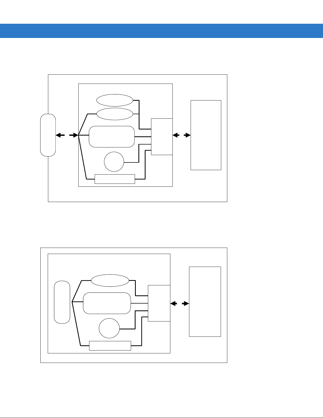
Symbol MS1204FZY, MS2204, MS2204VHD, and MS3204 Block Diagram
Interface Board
Beeper
External Beeper
DB9
Figure 1-2
flex flex
Symbol MS1204FZY, MS2204, MS2204VHD, and MS3204 Block Diagram
Interface Circuit
RS-232
Red/
Green
LED
External Trigger
Symbol MS954 Block Diagram
Interface Board
External Beeper
Interface
Decoded
Scan
Engine
DB9
Figure 1-3
Interface Circuit
RS-232
Red/
Green
LED
External Trigger
Symbol MS954 Block Diagram
Interface
flex
Decoded
Scan
Scan
Engine
Engine
Page 23

Getting Started 1 - 5
Miniscan Block Diagram Descriptions
Decoded Scan Engine - The scan engine emits a beam of laser light that reflects off the bar code to be decoded.
Black bars absorb light, white spaces reflect light. The scan engine collects the reflected light and processes the
signal through several analog filters. The filtered signal is digitized into a Digitized Barcode Pattern (DBP). Timing
information is analyzed by the decoder micro-controller to decode an d transmit the dat a contained in the bar code.
Data transmission is carried out using Motorola’s proprietary SSI Interface.
Interface Board - The interface board adapts the scan engine's interface into usable signals and data for the
intended host. It also contains a beeper (Symbol MS1204FZY/2204/2204VHD/3204 models only) and red/green
LED for audio/visual feedback, and provides for an external trigger and exter nal beeper.
The MiniScan interface board converts TTL level SSI signals to pro per RS-232 levels for connection to any RS-232
compliant host.
DB9 - The DB9 connector provides an outlet for the various interface signals used between a MiniScan scanner
and the host. It also maintains pin compatibility with the previous generation LS 1220 MiniScan host cables.
Page 24

1 - 6 Symbol MiniScan MSXX04 Series Integration Guide
Page 25

Chapter 2 Installation
Introduction
This chapter provides information on unpacking, mounting, and installing the MiniScan scanner.
Unpacking
Remove the MiniScan from its packing and inspect for damage. If the scan ner is damaged, call Motorola Enterprise
Mobility Support at the telephone number listed on page xv.
KEEP THE PACKING. It is the approved shipping container and should be used if the equipment needs to be
returned for servicing.
Page 26
2 - 2 Symbol MiniScan MSXX04 Series Integration Guide
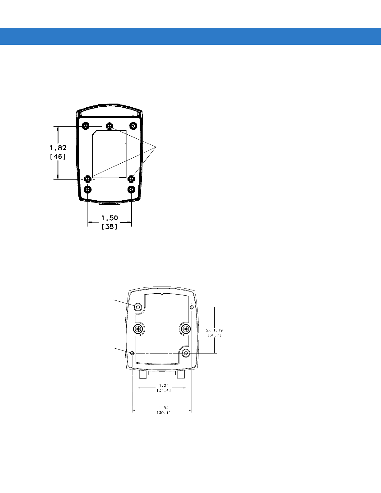
Mounting
There are three mounting holes (threaded inser t s) on th e bottom of the Symb ol MS1204FZY/2204/2204VHD/3204
chassis; two mounting holes on the Symbol MS954.
The following figures provide mounting dimensions for the MiniScan scanner housings. For a mounting template,
see Chapter 12, Mounting Templates.
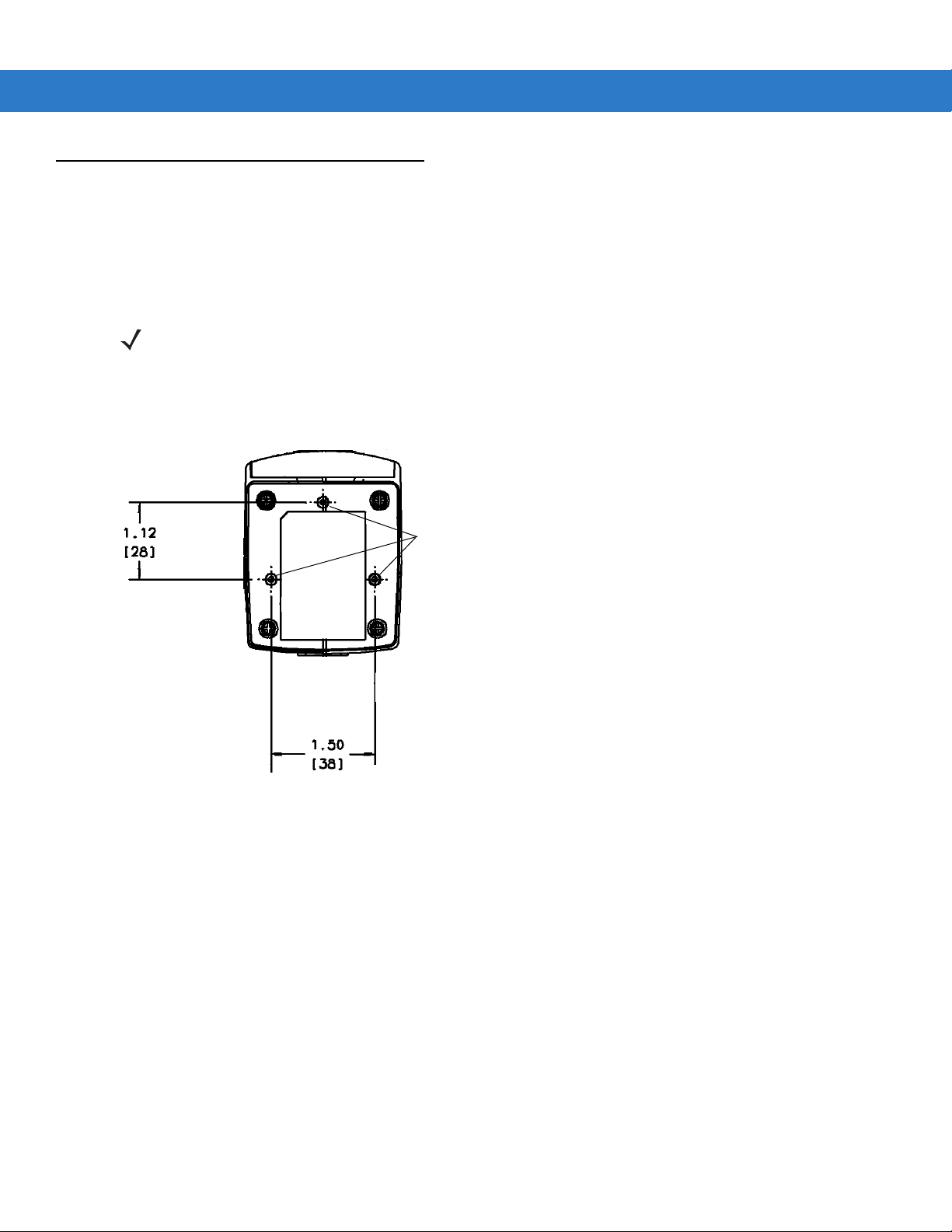
NOTE Use only non-magnetic M3x.5 screws with a maximum length of 3.6M to mount the MiniScan scanner
chassis.
Symbol MS1204FZY/MS2204/MS2204VHD Mounting Dimensions
Threaded Inserts
Figure 2-1
Note:
Dimensions are in inches [mm].
Symbol MS1204FZY/MS2204/MS2204VHD Mounting Dimensions
Page 27
Symbol MS3204 Mounting Dimensions
Threaded Inserts
Note:
Dimensions are in inches [mm].
Installation 2 - 3
Figure 2-2
Symbol MS3204 Mounting Dimensions
Symbol MS954 Mounting Dimensions
2x M3 - 3.6 mm lg. max.
Threaded Inserts
2x - 0.080 [2.0]
Alignment Holes
Note:
Dimensions are in inches [mm].
Figure 2-3
Symbol MS954 Mounting Dimensions
Page 28
2 - 4 Symbol MiniScan MSXX04 Series Integration Guide
Mounting the Scanner on the Stand
NOTE The stand is optional for the Symbol MS1204FZY, MS2204, MS2204VHD, and MS3204 only.
To mount the scanner on the optional stand:
1. Place the bottom of the scanner on the stand’s sca nner mount, aligning the scanner’s center threaded insert
(beneath the scan window) with the center mounting hole on the front of the stand. The two rear threaded
inserts on the bottom of the scanner will align with the proper mounting holes on the stand.
2. Secure the scanner to the stand using the three screws provided with the stand.
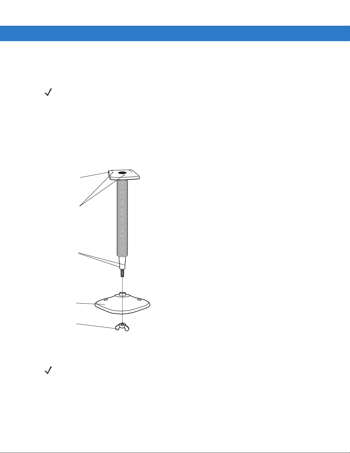
Assembling the Stand
1. Unscrew the wingnut
Scanner mount
from the bottom of the
one-piece scanner
mount.
Mounting holes
Flat areas
Stand base
Wingnut
Figure 2-4
Assembling the Stand
2. Fit the bottom of the
neck piece into the
opening on the top of the
stand base.
3. Tighten the wingnut
underneath the base to
secure the cup and neck
piece (see the note
below).
4. Bend the neck to the
desired position for
scanning.
NOTE Before tightening the wingnut under the base, ensure that the flat areas on the flexible neck fit securely in
the grooves in the base.
Page 29
Installation 2 - 5
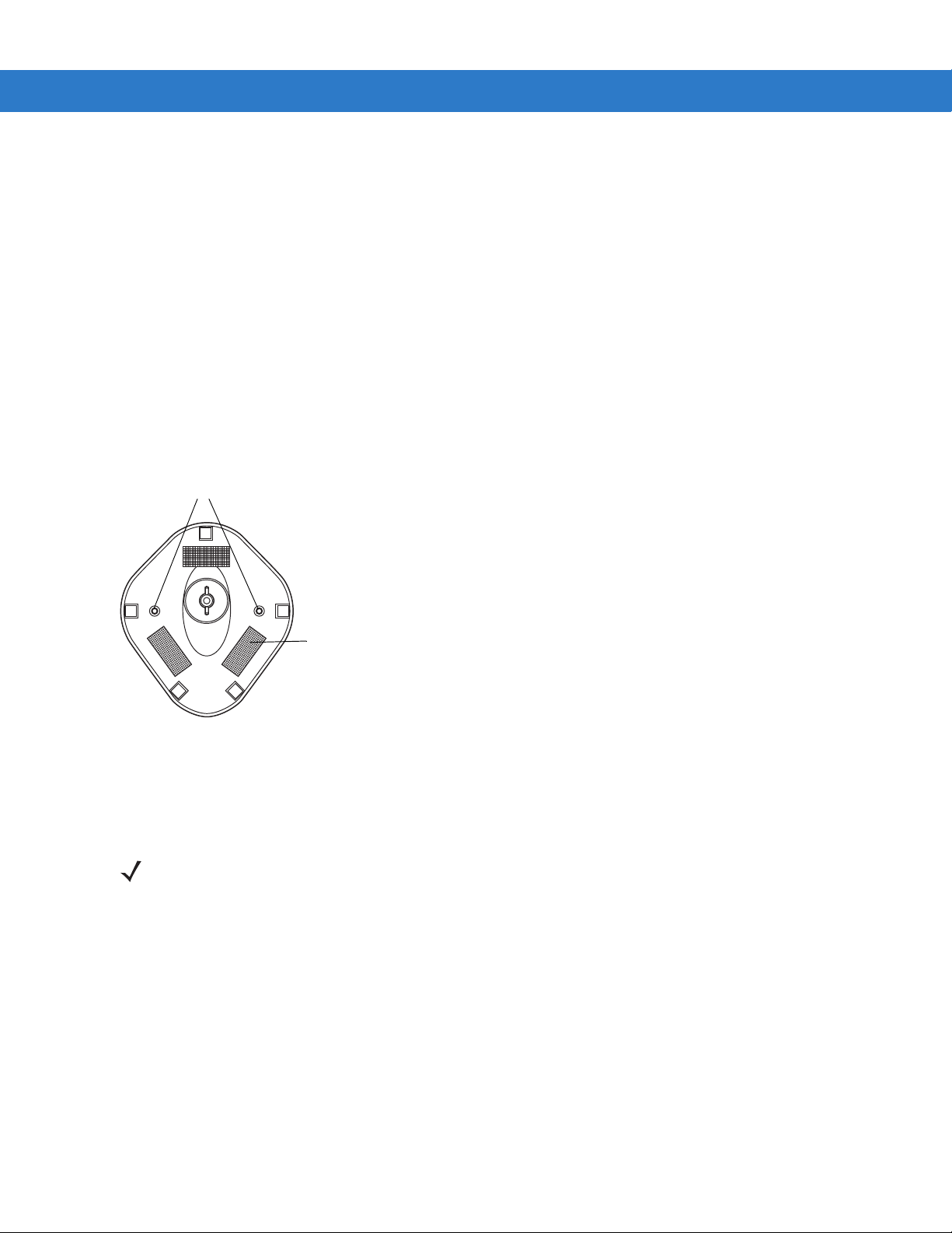
Mounting the Stand (optional)
You can attach the base of the scanner’s stand to a fl at surface using two screws or double-sided tape (not
provided).
Screw Mount
1. Position the assembled base on a flat surface.
2. Screw one #10 wood screw into each screw-mount hole until the base of the stand is secure.
Tape Mount
1. Peel the paper liner off one side of each piece of tape and place the sticky surface over each of the three
rectangular tape areas.
2. Peel the paper liner off the exposed sides of each piece of tape and press the stand on a flat surface until it is
secure.
Two screw-mount holes
Double-sided tape
areas (3 places)
(dimensions = 1” x 2”)
Figure 2-5
Mounting the Stand
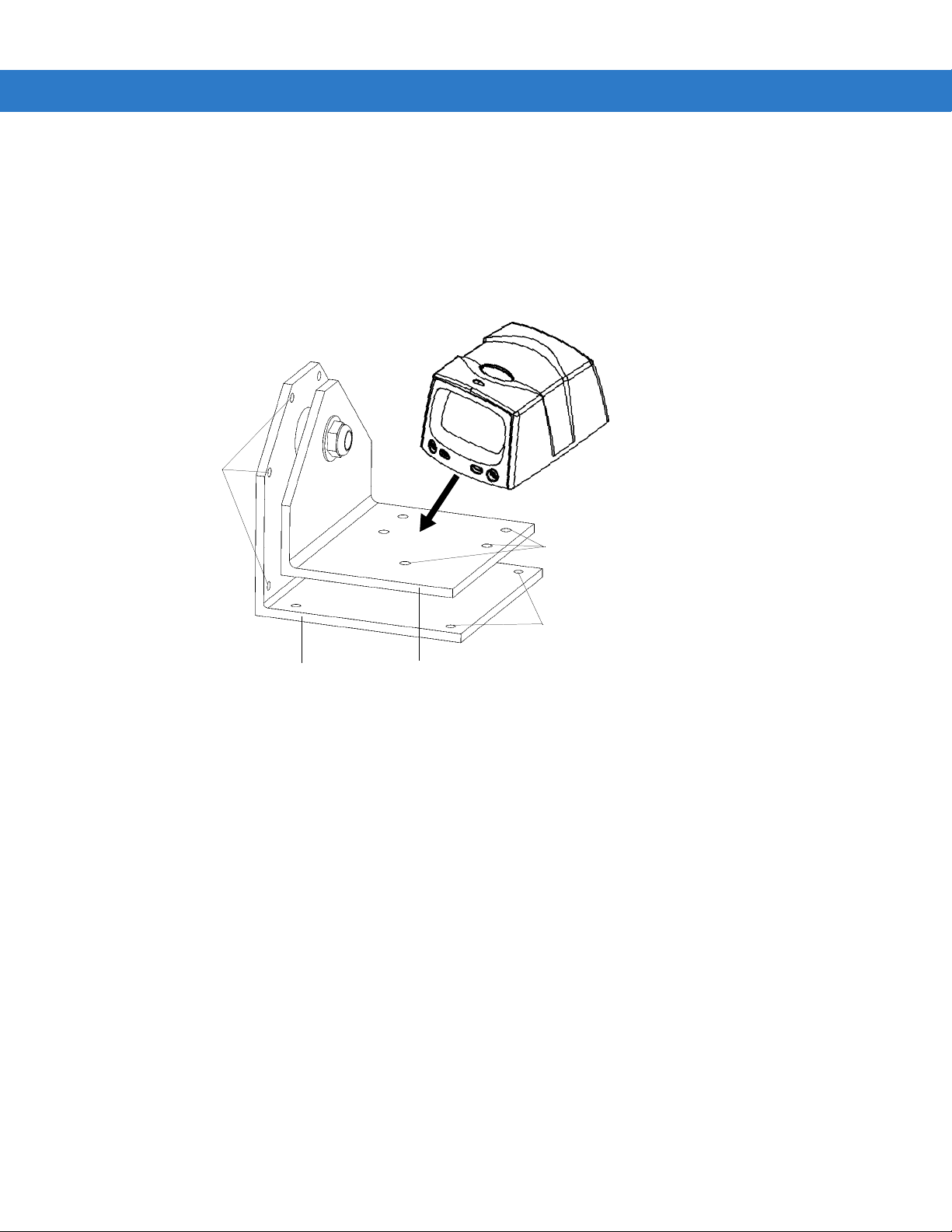
Mounting the Scanner on the Mounting Bracket
NOTE The mounting bracket is optional for the Symbol MS1204FZY, MS2204, MS2204VHD, and MS3204 only.
The optional mounting bracket kit consists of a scanner bracket, a moun ting br acket, and the h ardware re qui red to
mount the scanner. The bracket kit accommodates adjustable angles for optimal positioning of the scanner.
To mount the MiniScan scanner on the bracket, first secure the scanner to the scanner bracket, then attach the
mounting bracket to the wall (see Figure 2-6 on page 2-6):
1. Tilt the scanner bracket forward to access the center scanner mounting hole on the bracket.
2. Place the bottom of the scanner on the scanner br acket, aligning the scanner’s center threaded insert (b eneath
the scan window) with the center mounting hole on the scanner bracket.
3. Insert one of the screws provided through the mounting hole and into the scanner’s center threaded insert.
For the Symbol MS1204FZY, MS2204, and MS2204VHD, use a #0 Phillips screwdriver; for the Symbol
MS3204, use a #1 Phillips screwdriver.
Page 30
2 - 6 Symbol MiniScan MSXX04 Series Integration Guide
4. Tilt the scanner bracket in the opposite direction to access the rear scanner mounting holes (which ar e aligned
with the rear inserts on the bottom of the scanner), then insert the remaining two screws provided through the
two rear mounting holes and into the scanner’s threaded inserts.
5. Secure the mounting bracket to a flat surface by inserting 1/8” or smaller fasten ers through the surfac e and into
the bracket’s mounting holes. There are four mounting holes on the bottom of the mounting bracket for
horizontal mounting, and six holes on the side for vertical mounting.
Vertical
Mounting Holes
Scanner
Mounting Holes
Figure 2-6
Mounting Bracket
Scanner Bracket
Mounting the Scanner and Bracket
Horizontal
Mounting Holes
Page 31

Connecting the MiniScan
1
2
2
3
3
To connect the MiniScan to the host, connect the scanner cables in the order shown in Figure 2-7.
To Host
3
Installation 2 - 7
Beeper
(Optional)
5
Trigger or Photo
Sensor (Optional)
4
1
Trigger Jack (Optional)
See Figure 2-8
2
Figure 2-7
1
Figure 2-8
Typical Connection Diagram
Male jack shown for reference
Note: Due to many variations of
jack and socket styles, identify
terminals as shown before
soldering leads.
Trigger Jack Connector Pins
Insertion
Direction
1 - Ground (Sleeve)
1 - Ground (Sleeve)
2 - Battery (Middle Contact)
2 - Vcc (Middle Contact)
3 - Trigger (Tip)
3 - Trigger (Tip)
Page 32

2 - 8 Symbol MiniScan MSXX04 Series Integration Guide
Location and Positioning
CAUTION The location and positioning guidelines provided do not consider unique application characteristics. It
is recommended that an opto-mechanical engineer perform an opto-mechanical analysis prior to
integration.
NOTE Integrate the scanner in an environment no more extreme than the product’s specification, where the
scanner will not exceed its temperature range. For instance, do not mount the scanner onto or next to a
large heat source. When placing the scanner with another device, ensure there is proper convection or
venting for heat. Follow these suggestions to ensure product longevity, warranty, and overall satisfaction
with the scanner.
Using the MiniScan as an Embedded Scanner
The MiniScan can be mounted to read symbols that are automatically presented, or that are presented in a
pre-determined location. In these applications, MinScan positioning with respect to the symbol is critical. Failure to
properly position the MiniScan can result in unsatisfactory scanning performance. A thermal analysis is also
recommended.
Two methods of positioning the scanner are provided:
•
Use the Calculating the Usable Scan Length Method on page 2- 8 with consistently good quality symbols (see
page 2-9 for the Symbol MS954). This provides a mathematical solution to find the usable scan length.
•
The Testing the Usable Scan Length Method on page 2-10 uses real situation testing to adjust the usable
scan length to fit the application conditions.
Calculating the Usable Scan Length Method
Calculate usable scan length as follows (see Figure 2-9 on page 2-9):
L = 1.8 x (D+d+B) x Tan (A/2)
Table 2-1
MS1204FZY (Default) 1.17 42°
MS1204FZY (Narrow Mode) 1.17 30°
MS2204 1.53 34°
MS2204VHD 1.53 34°
Calculation Constants
Constants B A
MS3204 1.93 34°
Page 33

Installation 2 - 9
r
e
where:
D = Distance (in inches) from the front edge of the host housing to the bar code.
d = The host housing’s internal optical path from the edge of the housing to the front of the MiniScan scanner.
B = Internal optical path from the scan mirror to the front edge of the MiniScan scanner.
A = Scan angle in degrees.
NOTE Usable scan length is determined by this formula, or 90% of scan line at any working distance. This
formula is based on good quality symbols in the center of the working range and length of bar code.
Calculating the Usable Scan Length Method (Symbol MS954 Only)
Calculate usable scan length as follows (see Figure 2-9 on page 2-9):
L = 2.0 x (D+d+B) x Tan (A/2)
Table 2-2
Symbol MS954 Calculation Constants
Constants B A
MS954 0.87 47°
MS954 (Narrow Mode) 0.87 35°
where:
D = Distance (in inches) from the front edge of the host housing to the bar code.
d = The host housing’s internal optical path from the edge of the housing to the front of the MiniScan scanner.
B = Internal optical path from the scan mirror to the front edge of the MiniScan scanner.
A = Scan angle in degrees.
NOTE The Symbol MS954 does not require margin on either side of the bar code to decode. The 47° scan line
provides identical scanning performance to older minscan devices (e.g., Symbol MS923) with a scan line
of 53°.
Consider the width of the scan line at any given distance when designing a system.
Ba
Cod
Host System
MiniScan
Figure 2-9
A
B
d D
Usable Scan Length Diagram
1/2 L
L
1/2 L
Page 34

2 - 10 Symbol MiniScan MSXX04 Series Integration Guide
Testing the Usable Scan Length Method
Due to the variety of symbol sizes, densities, print quality, etc., there is no simple way to calculate the ideal symbol
distance. To op tim ize per fo rm a nc e, us e th e Testing The Usable Scan Length positioning method:
1. Measure the maximum and minimum distances at which the symbols can be read.
2. Check the near and far range on several symbols. If they are not reasonably consistent there ma y be a printing
quality problem that can degrade the performance of the system. Motorola can provide advice on how to
improve the installation.
NOTE Poor quality symbols (from bad printing, wear, or damage) may not decode well when placed in the center
of the depth of field (especially higher density codes). The scan beam has a minimum width in the central
area, and when the scanner tries to read all symbol imperfections in this area it may not decode. After a
preliminary spot is determined using good quality symbols, test several reduced quality symbols and
adjust the spot for the best overall symbol position.
3. Locate the scanner so the symbol is near the middle of the near/far range.
4. Center the symbol (left to right) in the scan line whenever possible.
5. Position the symbol so that the scan line is as near as possible to perpendicular to the bars and spaces in the
symbol.
6. Avoid specular reflection (glare ) off th e symbol by tilting the top or bottom of the symbol away from the scanner .
The exact angle is not critical, but it must be large enough so that if a mirror were inserted in the symbol
location, the reflected scan line would miss the front surface of the scanner. For the maximum allowable angles
refer to the Skew, Pitch and Roll ang les listed in each MiniScan Technical Specifications table.
7. If an additional window is to be placed between the scanner and the symbol, determine the optimum symbol
location using a representative window in the desired window po sitio n .
8. Give the scanner time to dwell on the symbol for several scans. When first enabled, the MiniScan may take two
or three scans before it reaches maximum pe rforman ce . Enable the MiniScan before the symbol is presented,
if possible.
Page 35

Installation 2 - 11
Conveyor Applications
Conveyor applications require setting the conveyor velocity to optimize the scanner’s ability to read symbols. Also
consider the orientation of the symbol with respect to the conveyor direction. Figure 2-10 on page 2-11 illustrates
the relationship of the conveyor velocity with respect to a symbol positioned perpendicular to the conveyor direction
and Figure 2-11 on page 2-12 illustrates the relationship of the conveyor velocity with respect to a symbol
positioned parallel to the conveyor direction.
Symbol is Perpendicular to Conveyor Movement
With the symbol bars perpendicular to the conveyor belt direction (Picket Fence presentation) the relationship is:
V = (R x (F-W)) / N
where: V = Velocity of the conveyor (inches/second)
R = Scan Rate (see technical specifications)
F = 80% of width of scan beam
W = Symbol Width (inches)
N = Number of scans over symbol (minimum of 10 scans)
F=Field Width
W=Symbol Width
Direction of Conveyor Perpendicular to Symbol
Scan Beam
Figure 2-10
Symbol Perpendicular To Conveyor Movement
Example
R = 640 scans per second
F = 80% of 6 in.
W = 4 in.
N = 10
V = (640 x ((0.8 x 6) - 4))) / 10 = 51.2 in./sec
Page 36

2 - 12 Symbol MiniScan MSXX04 Series Integration Guide
Symbol is Parallel to Conveyor Movement
With the symbol bars parallel to the conveyor belt direction (ladder presentation) the relationship is:
V = (R x H) / N
where: V = Velocity of the conveyor (inches/second)
R = Scan Rate of scanner (see technical specifications)
H = Symbol height
N = Number of scans over symbol (minimum of 10 scans)
H=Symbol Height
Scan Beam
Direction of Conveyor Parallel to Symbol
Figure 2-11
Symbol Parallel To Conveyor Movement
Example
Use the previous formula to calculate the number of scans fo r a specific bar code, scanner, and conveyor speed; a
minimum of 10 scans per symbol is recommended.
R = 640 scans/sec
H = 60 mil
N = 10 scans
V = (640 x .060) / 10 = 3.84 in./sec
Embedded Applications Requiring a Window
Use the following guidelines for applications that require a window in front of the MiniScan.
NOTE Motorola does not recommend placing an exit window in front of the MiniScan; however, the following
information is provided for applications that require such a window.
Window Material
Many window materials that look perfectly clear can contain stresses and distortions that can reduce scanner
performance. For this reason, only optical glass or cell-cast acrylic with an anti-reflection coating is highly
recommended. Following is a description of acrylic, and CR-39, another popular window material. T able 2-3 on
page 2-13 outlines the suggested window properties.
Page 37

Installation 2 - 13
CAUTION Consult an opto-mechanical engineer to recommend an appropriate window material and to
determine if coatings are appropriate for the specific application.
NOTE Do not use polycarbonate material.
Acrylic
When fabricated by cell-casting, acrylic has very good optical quality and low initial cost. However, protect the
surface from the environment as acrylic is susce pt ible to attack by chemicals, mechanical stresses, and UV light.
Acrylic has reasonably good impact resistance and can be ultrasonically welded.
CR-39
CR-39 is a thermal-setting plastic produced by the cell-casting process, and is commonly used in plastic eye
glasses lenses. CR-39 has excellent chemical and environmental resistance, including good surface hardness.
Typica lly it does not require hard- coating , but can be hard coated for severe environments. CR-39 has reasonably
good impact resistance and cannot be ultrasonically welded.
Chemically Tempered Float Glass
Glass is a hard material which provides excellent scratch and abrasion resistance. However, unannealed glass is
brittle. Increasing flexibility strength with minimal optical distortion requires chemical tempering. Glass cannot be
ultrasonically welded and is difficult to cut into odd shapes.
Table 2-3
Material Red cell-cast acrylic.
Spectral Transmission 85% minimum from 640 to 690 nanometers.
Thickness 0.059 ± 0.005
Wavefront Distortion (transmission) 0.2 wavelengths peak-to-valley maximum over any 0.08 in. diameter within
Clear Aperture To extend to within 0.04 in. of the edges all around.
Surface Quality 60-20 scratch/dig
Coating Both sides to be anti-reflection coated to provide 0.5% max reflectivity
Suggested Window Properties
Property Description
the clear aperture.
(each side) from 640 to 690 nanometers at nominal window tilt angle.
Coatings must comply with the hardness adherence requirements of
MIL-M-13508.
Page 38

2 - 14 Symbol MiniScan MSXX04 Series Integration Guide
Window Coatings
Table 2-4 on page 2-14 lists some exit window manufacturers and anti-reflection coaters.
Anti-Reflection Coatings
Apply an anti-reflection coating to the inside and/or out side of the window to significantly reduce the amount of light
reflected off the window, back into the scan engine. The coating can also improve the range of accept able window
positions and minimize performance degradation due to signal loss as the light pa sses through the window. Using
anti-reflection coatings on both the inside and outside of the window is high ly recommended.
Polysiloxane Coating
Polysiloxane type coatings are applied to plastic surfaces to improve the surface resistance to both scratch and
abrasion. They are usually applied by dipping, then air-drying in an oven with filtered hot air.
Table 2-4
Evaporated Coatings, Inc.
2365 Maryland Road
Willow Grove, PA 19090
(215) 659-3080
Fosta-Tek Optics, Inc.
320 Hamilton Street
Leominster, MA 01453
(978) 534-6511
Glasflex Corporation
4 Sterling Road
Sterling, NJ 07980
(908) 647-4100
Optical Polymers Int. (OPI)
110 West Main Street
Milford, CT 06460
(203)-882-9093
Window Manufacturers and Coaters
Company Discipline Specifics
Anti-reflection coater Acrylic window supplier
Anti-reflection coater
Cell-caster, hard coater,
laser cutter
Cell-caster Acrylic exit window
CR-39 cell-caster, coater,
laser cutter
CR39 exit window
manufacturer
manufacturer
CR39 exit window
manufacturer
Polycast
70 Carlisle Place
Stamford, CT 06902
800-243-9002
TSP
2009 Glen Parkway
Batavia, OH 45103
800-277-9778
acrylic cell-caster, hard
coater, laser cutter
acrylic cell-caster, coater,
laser cutter
Acrylic exit window
manufacturer
Acrylic exit window
manufacturer
Page 39

Installation 2 - 15
Embedded Window Angle and Position
If a window is placed between the MiniScan and the item to be scanned, observe the following guidelines:
•
Window Clear Opening - Make the clear opening of the window large enough so that the entire scan beam
passes through the window. Cutting off any part of the beam can result in internal reflections and degrade
decode range performance. Ensure that window placement relative to the MiniScan accounts for tolerances
on all parts involved in that assembly.
•
Window Angle - Angle the window at least 2o more than the tilt of the window on the scanner (see Table
2-5). Further tilting the window is acceptable and decreases the possibility of a secondary reflection from that
window degrading the scanner's performan ce.
•
Optical Working Range - Adding a window can reduce the working range of the scanner since there is a
signal loss when passing through window material. To minimize this reduction, use a special coating
described in Window Coatings on page 2-14. To understand the difference, test the scanner in the desired
orientation and see if the difference affects scanner performance.
Table 2-5
Secondary Window Angles
MiniScan Model
MS954
MS1204FZY, MS2204, MS2204VHD
MS3204
MiniScan Exit Window Angle
from Vertical
o
28
o
30
o
35
Minimum Secondary Window
Angle from Vertical
o
30
o
32
o
37
Page 40

2 - 16 Symbol MiniScan MSXX04 Series Integration Guide
Accessories
The following accessories are available for the MiniScan scanner, and can be found in Symbol’s Solution Builder
(ordering guide).
•
For power connection
• 110V power supply, US, p/n 50-14000-008
• 220V power supply, Europe, p/n 50-14000-009
• 100V power supply, Asia, p/n 50-14000-010
• 264V Universal power supply (also order cables below), p/n 50-14001-001
• DC line cord (power supply to scanner), p/n 50-16002-009
• AC line cord (wall outlet to power supply), p/n 23844-00-00
•
RS-232
• Female DB9 with straight connector to RS-232 host (female DB9), with trigger jack and no beeper, p/n
25-13227-XX
• Female DB9 with straight connector to RS-232 host (female DB9), with trigger jack and beeper, p/n
25-13228-XX
• Female DB9 with straight connector to RS-232 host (female DB9),
p/n 25-58918-XX
• Female DB9 with right angle connector to RS-232 host (female DB9),
p/n 25-58919-XX
• Female DB9 with straight connector to RS-232 host (female DB9), with trigger jack and no hardware
handshaking, p/n 25-63736-XX
•
Cable Adapters
• Female 25 pin D, TxD on pin 2, p/n 50-12100-378
• Female 25 pin D, TxD on pin 3, p/n 50-12100-377
• Male 25 pin D, TxD on pin 2, p/n 50-12100-380
• Male 25 pin D, TxD on pin 3, p/n 50-12100-379
•
Optional Accessories
• Push button trigger cable, p/n 25-04950-01R
• Photo sensor trigger cable, p/n 25-13176-01R (retroreflective, IR 850 nm, 7 foot range)
• Fixed-mount stand, p/n 20-60136-01R
• Mounting bracket, p/n KT-65578-01R
Page 41

Installation 2 - 17
Simple Serial Interface Software Developer's Kit (SSISDK)
The Software Developer's Kit, available from Motorola’s website, provides the software tools required to integrate
and communicate with the MiniScan scanners, including:
•
Sample Windows® program with source code
•
DLL with source code for building user applications
•
ActiveX component (including help file) for easy integration into VisualBasic programs
•
Simple Serial Interface documentation.
With over 70 programmable parameters, MiniScan scanners can be configured by scanning bar code menus, or
through the serial interface using Symbol’s Simple Serial Interface protocol.
For Windows
scanner's features and obtain maximum performance.
®
, DOS, and embedded system environments, this enables the user to take full advantage of the
Page 42

2 - 18 Symbol MiniScan MSXX04 Series Integration Guide
Page 43

Chapter 3 Scanning
Introduction
This chapter provides information on scan patterns, sca nning, triggering options, and beeper and LED definitions.
MiniScan Scan Patterns
Symbol MS1204FZY / MS954 Scan Pattern
Symbol MS1204FZY and MS954 scanners emit a single scan line to quickly decode 1D bar codes.
Figure 3-1
Single Scan Line Scan Pattern
Page 44

3 - 2 Symbol MiniScan MSXX04 Series Integration Guide
Symbol MS2204 and MS2204VHD Scan Patterns
The Symbol MS2204 and MS2204VHD generate different scan patterns (Smart Raster and High Density Single
Scan Line) based on the software command received at the interface. The raster pattern can be used to read 1D
bar codes and PDF417 symbols.
NOTE The Symbol MS2204 and MS2204VHD also support omnidirectional and semi-omn idirectional scan
patterns, but are not optimized for these patterns.
Smart Raster Scan Pattern
The Symbol MS2204 and MS2204VHD can create a single line which opens vertically to read PDF417 symbols
using the Smart Raster feature. This feature autodetects the type of bar code b eing scanned and adju sts it s pa ttern
accordingly, providing optimal performance on 1D, PDF417, GS1 DataBar, and Composite codes.
Stage 1: “Slab” Raster Pattern
Stage 2: Open Raster Pattern
Figure 3-2
Raster Scan Pattern
High Density Single Scan Line Scan Pattern
The High Density single scan line appears as a "mini" raster and scans multiple areas of
1D codes to swiftly and accurately capture data on poorly printed and damaged bar codes.
Figure 3-3
High Density Single Scan Line Scan Pattern
Page 45

Scanning 3 - 3
Symbol MS3204 Scan Patterns
The Symbol MS3204 generates four scan patterns based on the software command received at the interface.
These patterns are Smart Raster, Semi-omnidirectional, Omnidirectional, and High Density Single Scan Line. The
raster pattern can be used to read 1D bar codes and PDF417 symbols. The omnidirectio nal pattern reads 1D bar
codes in an omnidirectional manner.
Smart Raster Scan Pattern
The Symbol MS3204 can create a single line which opens vertically to read PDF417 symbols using the Smart
Raster feature. This feature autodetects the type of bar code being scanned and adjusts its pattern accordingly,
providing optimal performance on 1D, PDF417, GS1 DataBar, and Composite codes.
Stage 1: “Slab” Raster Pattern
Stage 2: Open Raster Pattern
Figure 3-4
Raster Scan Pattern
Semi-omnidirectional Scan Pattern
The semi-omnidirectional pattern is an alternative to the full omnidirectional pattern that scans highly truncated 1D
and GS1 DataBar bar codes. Present bar codes horizontally with no more than a 20
Figure 3-5
Semi-omnidirectional Scan Pattern
o
tilt.
Page 46

3 - 4 Symbol MiniScan MSXX04 Series Integration Guide
Omnidirectional Scan Pattern
The high-speed rotating omnidirectional scan pattern provides aggressive performance on 1D bar codes because
there are no “holes” in the pattern. This ensures fast throughput at the point of activity and the ability to read 1D
symbols in 360
o
of rotation, eliminating the need to orient the bar code in the field of view.
Figure 3-6
Omnidirectional Scan Pattern
High Density Single Scan Line Scan Pattern
The high density single scan line appears as a "mini" raster and scans multiple areas of
1D codes to swiftly and accurately capture data on poorly printed and damaged bar codes.
Figure 3-7
High Density Single Scan Line Scan Pattern
Scan Angle Selection
The Symbol MS1204FZY and MS954 scanners support two pre-set scan angles (see each scanner’s technical
specifications)
Selecting Scan Angle via SSI
To use SSI to select the scan angle, issue the SSI PARAM_SEND command with the NUM_SCAN_ANGLE (191)
parameter number. This is set to the default angle (182), or can be set to the alternate angle (181). Se e the Simple
Serial Interface (SSI) Programmer’s Guide (p/n 72-40451-xx) for more information.
Selecting Scan Angle via Parameter Bar Code
.
The scan angle can also be set by scanning a parameter bar code (see Scan Angle on page 10-12). Once the
parameter bar code is scanned, that scan angle setting is retained.
Operation in Blink Mode
The scan angle during Blink Mode is determined by the scan angle system parameter.
Page 47

Scanning Tips
When scanning, make sure the symbol to be scanned is within the scanning range. See Calculating the Usable
Scan Length Method on page 2-8. Align the bar code with the scan beam. The gr een decode LED light s to indicate
a successful decode.
Scan the Entire Symbol
•
The scan beam must cross every bar and space on the symbol.
•
The larger the symbol, the farther away the scanner should be positioned.
•
Position the scanner closer for symbols with bars that are close together.
Scanning 3 - 5
Position at an Angle
Do not position the scanner exactly perpendicular to the bar code. In this position, light can bounce back into the
scanner's exit window and prevent a successful decode.
Trigger Options
Continuous
The laser is enabled continuously and decode processing is continuously active. The scanner can be configured to
scan and transmit a bar code, and then not decode the same bar code or any bar code for a set pe riod of time. See
Timeout Between Decodes on page 10-18 to customize the application to the rate at which bar codes are
presented.
RIGHT
012345
WRONG
012345
Continuous
NOTE This option is not recommended during scanner programming via bar code menus.
Page 48

3 - 6 Symbol MiniScan MSXX04 Series Integration Guide
Level Trigger
The laser is enabled and decode processing begins when the trigger line is activated. Decode processing
continues until a good decode occurs, the trigger is released, or the Laser On Time expires. The laser is disabled
once decode processing is complete. The next decode attempt will not occur until the trigger line is released and
then reactivated.
Pulse Trigger
The laser is enabled and decode processing begins when the trigger line is activated. Decode processing
continues regardless of the trigger line until a good decode occurs, or until the Laser On Time expires. The la ser is
disabled once decode processing is complete. The next decode attempt will not occur until the trigger line is
released and then reactivated.
Level
Pulse
Blink
NOTE This option is supported by the Symbol MS1204FZY and MS954 only.
The laser blinks at a 25% duty cycle (reduced to 10% after 30 seconds of inactivity), until a bar code is presented.
When a bar code is presented, the laser remains on until either the bar code is decoded or removed, or the session
timeout expires. Once the bar code is decoded, the scanner will not decode it again until the bar code is removed.
Blink
Host Trigger
The laser is enabled and decode processing begins in response to an SSI Start Decode message from th e host.
Decode processing continues until a good decode occurs, an SSI Stop Decode message is received, or the Laser
On Time expires. The laser is disabled once decode processing is complete. The next decode attempt will not
occur until the next Start Decode message is received.
Host
Page 49

Beeper and LED Definitions
Table 3-1 provides beeper defin itions, and Table 3-2 provides LED definitions.
Scanning 3 - 7
Table 3-1
Standard Use
1 Beep - short high tone A bar code symbol was decoded (if decode beeper is enabled).
1 Beep - long high tone Thermal shutdown.
3 Beeps - short high tone
(MS2204/2204VHD/3204 only)
Parameter Menu Scanning
2 Beeps - short high tone Correct entry scanned or correct menu sequence performed.
1 Beep - hi/lo/hi/lo tone Successful program exit with change in the parameter setting.
2 Beeps - lo/hi tone Input error, incorrect bar code, or Cancel scanned, wrong entry, incorrect bar
Communication
4 Beeps - short high tone Communication error.
4 Beeps - hi/hi/hi/lo Receive error.
Beeper Definitions
Beeper Sequence Indication
Power-on or reset. Occurs immediately after the scanner is turned on,
indicating that the system software is working properly. If three beeps occur
during normal operation, it is due to a reset and any work in progress is lost. If
this occurs often, contact Motorola Enterprise Mobility Support.
code programming sequence; remain in program mode.
3 Beeps - lo/hi/lo ADF transmit error.
Table 3-2
Red Scanner is on.
Green A bar code was successfully decoded.
LED Definitions
LED Indication
Page 50

3 - 8 Symbol MiniScan MSXX04 Series Integration Guide
Page 51

Chapter 4 Symbol MS1204FZY Specifications
Introduction
This chapter provides the technical specifications for the Symbol MS1204FZY scanner.
Symbol MS1204FZY Electrical Interface
Figure 4-1
MiniScan Connector
Page 52

4 - 2 Symbol MiniScan MSXX04 Series Integration Guide
Table 4-1 lists the pin functions of the Symbol MS1204FZY interface.
Table 4-1
Pin No. Pin Name Type* Function
1 Trigger I Signals scanner to begin scanning session.
2 TXD O Serial data transmit output. Drives the serial data receive input on the
3 RXD I Serial data receive input. Driven by the serial data transmit output on
4 Not used
5 Ground Power supply ground input and signal ground reference.
6 Power I 5.0 VDC ± 10%
7 CTS I Clear-to-send handshaking input line, used only in conjunction with the
8 RTS O Request-to-send handshaking output line, used only in conjunction
9 Beeper/Download I/O During normal operation this signal functions as an external beeper
Symbol MS1204FZY Electrical Interface
device communicating with the scanner.
the device communicating with the scanner.
RTS line. Optionally used by another device to signal the scanner to
begin transmitting data.
with the CTS line. Optionally used by the scanner to signal another
device that data is available to send.
drive line. This signal can sink 50 mA of current to drive an external
beeper, and is normally pulled up. This signal is also used to begin
Flash Download operation when grounded externally during power up.
*I = Input O = Output
Page 53

Symbol MS1204FZY Mechanical Drawings
Symbol MS1204FZY Specifications 4 - 3
Notes:
Unless otherwise specified:
•
Dimensions are in inches,
dimensions in [ ] are mm.
•
User mounting tolerances are not
included.
Figure 4-2
Symbol MS1204FZY Mechanical Drawing
Page 54

4 - 4 Symbol MiniScan MSXX04 Series Integration Guide
Notes:
Unless otherwise specified:
•
Dimensions are in inches,
dimensions in [ ] are mm.
•
User mounting tolerances are
not included.
Figure 4-3
Symbol MS1204FZY Mechanical Drawing
Page 55

Symbol MS1204FZY Technical Specifications
Table 4-2 provides the Symbol MS1204FZY technical specifications.
Symbol MS1204FZY Specifications 4 - 5
Table 4-2
Power Requirements
Laser Power 1.0 mW ± 0.12 mW,
Scan Rate 36 (± 5) scans/sec (bidirectional)
Print Contrast Minimum 25% absolute dark/light reflectance measured at 650 nm.
Scan Angle Default (Wide): 42° ± 2°
Scan Pattern Single scan line
Skew Tolerance ± 50° from normal (see
Pitch Angle ± 65° from normal (see
Roll ± 20° from ve rtical (see
Symbol MS1204FZY Technical Specifications @ 23°C
Item Description
Input Voltage
Scanning Current
Standby Current
V
Noise Level
cc
5.0 VDC ±10%
160 mA ±40 mA
20 mA ±5 mA typical
200 mV peak-to-peak max.
λ
Alternate (Narrow): 30° ± 2°
= 650 nm nominal
Figure 4-4 on page 4-6
Figure 4-4 on page 4-6
Figure 4-4 on page 4-6
)
)
)
Decode Depth of Field See
Ambient Light Immunity
Sunlight
Artificial Light
Drop Multiple 30” drops
Vibration Unpowered scanner withstands a random vibration along each of the
ESD ± 20kV air discharge
Sealing IP54
Operating Temperature -4° to 122°F (-20° to 50°C)
Storage Temperature -40° to 158°F (-40° to 70°C)
Humidity 5% to 95% non-condensing
Note: Environmental and/or tolerance parameters are not cumulative.
Figure 4-5 on page 4-7
8,000 ft. candles (86,112 lux)
450 ft. candles (4,844 lux)
X, Y and Z axes for a period of one hour per axis, defined as follows:
20 to 80 Hz Ramp up to 0.04 G^2/Hz at the rate of 3dB/octave.
80 to 350 Hz 0.04 G^2/Hz
350 to 2000 Hz Ramp down at the rate of 3 dB/octave.
± 8kV indirect discharge
Page 56

4 - 6 Symbol MiniScan MSXX04 Series Integration Guide
Table 4-2
Symbol MS1204FZY Technical Specifications @ 23°C (Continued)
Item Description
Laser Class CDRH Class II, IEC Class 2
Height 1.60 in. (4.06 cm)
Width 2.28 in. (5.79 cm)
Depth 2.94 in. (7.47 cm)
Weight 4.45 oz. (126 gm)
Note: Environmental and/or tolerance parameters are not cumulative.
Skew Pitch
+ 50° from normal
Skew
20 mil
Symbol
Angle
+ 65° from normal
20 mil
Symbol
Pitch
Angle
Scan Beam
15.0 in. (381 mm)
Roll
Roll
Angle
20 mil
Symbol
Scan Beam
Scan Beam
15.0 in. (381 mm)
+ 20° from normal
Note: Tolerances are
reduced at extreme ends
of the working range.
15.0 in. (381 mm)
Figure 4-4
Skew, Pitch and Roll
Page 57

Symbol MS1204FZY Decode Zone
The scanner has a selectable scan angle of either 30° or 42°. The 42° symbol decodes are shown in Figure 4-5. The
figures shown are typical values. Table 4-3 on page 4-8 lists the typical and guaranteed dist ances for th e 42° sca n
angle for selected bar code densities. The minimum element width (or “symbol density”) is the width in mils of the
narrowest element (bar or space) in the symbol. The maximum usable length of a symbol at any give n range is
shown below. To calculate this distance, see Calculating the Usable Scan Length Methodon page 2-8.
Note: Typical performance at 68˚F (20˚C)
on high quality symbols.
MS-120XFZY
5 mil
7.00
3.25
7.5 mil
3.00
2.20
1.00
2.20
4.00
12.50
mil
13
UPC
100%
20 mil * (80% MRD)
20 mil * (25%MRD)
25.75
34.00
27.25
40 mil *
55 mil *
66.75
Symbol MS1204FZY Specifications 4 - 7
in
cm
35
88.9
30
76.2
25
63.5
20
50.8
W
38.1
i
d
25.4
t
h
12.7
o
0
f
12.7
F
i
25.4
e
l
38.1
d
50.8
63.5
76.2
88.9
75.00
15
10
5
0
5
10
15
20
25
30
35
0
In.
0
cm
Figure 4-5
12.7
5
25.4
38.1
50.8
63.5
76.2
88.9
101.6
114.3
127.0
139.7
152.4
165.1
60
55
50
45
40
35
30
25
20
15
10
177.8
75
190.5
70
65
Depth of Field
*Minimum distance determined by symbol length and scan angle
Symbol MS1204FZY Typical Decode Zone (42o Scan Angle)
Page 58

4 - 8 Symbol MiniScan MSXX04 Series Integration Guide
Table 4-3
Symbol MS1204FZY Decode Distances (42o Scan Angle)
Symbol Density/
p/n / Bar Code Type /
W-N Ratio
5.0 mil
64-17453-01
Code 39; 2.5:1
7.5 mil
64-17452-01
Code 39; 2.5:1
13 mil
64-05303-01
100% UPC
20 mil
60-01429-01
Code 39; 2.2:1
20 mil
60-02710-01
Code 39; 2.2:1
Bar Code Content/
Contrast
ABCDEFGH
80% MRD
ABCDEF
80% MRD
012345678905
80% MRD
123
80% MRD
123
25% MRD
Guaranteed Working
Typical Working Ranges
1
3
Ranges
3
Near Far Near Far
3.25 in.
8.26 cm
3.00 in.
7.62 cm
2.20 in.
5.59 cm
1.00 in.
2.54 cm
7.00 in.
17.78 cm
12.50 in.
31.75 cm
25.75 in.
65.41 cm
34.00 in.
86.36 cm
4.75 in.
12.07 cm
4.75 in.
12.07 cm
5.25 in.
13.34 cm
9.00 in.
22.86 cm
Note 2 19.00 in.
48.26 cm
Note 2 24.00 in.
60.96 cm
(Note 2)
1.00 in.
2.54 cm
27.25 in.
69.22 cm
Note 2 22.00 in.
55.88 cm
(Note 2)
40 mil
64-17457-01
Code 39; 2.2:1
55 mil
64-17458-01
Code 39; 2.2:1
AB
80% MRD
CD
80% MRD
2.20 in.
5.59 cm
(Note 2)
4.00 in.
10.16 cm
(Note 2)
66.75 in.
169.55 cm
75.00 in.
190.50 cm
Note 2 49.00 in.
124.46 cm
Note 2 55.00 in.
139.70 cm
Notes:
1. Contrast measured as Mean Reflective Difference (MRD) at 650 nm.
2. Near ranges on lower densities largely depend on the width of the bar code and the scan angle.
3. Working range specifications: Photographic quality symbols, pitch = 10°, skew = 0°, roll = 0°,
ambient light < 150 ft. candles, and temperature = 23 °C.
Usable Scan Length
The decode zone is a function of various symbol characteristics including density, print contrast, wide-to-narrow
ratio, and edge accuracy. Consider the width of the scan line at any given distance when designing a system.
Calculating the Usable Scan Length Methodon page 2-8 describes how to calculate the usable scan length. The
scan angle is provided in Table 4-2 on page 4-5.
Page 59

Chapter 5 Symbol MS2204 Specifications
Introduction
This chapter provides the technical specifications for the Symbol MS2204 scanner.
Symbol MS2204 Electrical Interface
Figure 5-1
MiniScan Connector
Page 60

5 - 2 Symbol MiniScan MSXX04 Series Integration Guide
Table 5-1 lists the pin functions of the Symbol MS2204 interface.
Table 5-1
Pin No. Pin Name Type* Function
1 Trigger I Signals scanner to begin scanning session.
2 TXD O Serial dat a transmit output. Drives the serial data receive inp ut on the
3 RXD I Serial data receive input. Driven by the serial data transmit output on
4 Not used
5 Ground Power supply ground input and signal ground reference.
6 Power I 5.0 VDC ± 10%
7 CTS I Clear-to-send handshaking input line, used only in conjunction with
8 RTS O Request-to-send handshaking output line, used only in conjunction
9 Beeper/Download I/O During normal operation this signal functions as an external beeper
Symbol MS2204 Electrical Interface
device communicating with the scanner.
the device communicating with the scanner.
the RTS line. Optionally used by a nother device to signal the scanner
to begin transmitting data.
with the CTS line. Optionally used by the scanner to signal another
device that data is available to send.
drive line. This signal can sink 50mA of current to drive an external
beeper, and is normally pulled up. This signal is also used to begin
Flash Download operation when grounded externally during power
up.
*I = Input O = Output
Page 61

Symbol MS2204 Mechanical Drawings
Symbol MS2204 Specifications 5 - 3
Notes:
Unless otherwise specified:
• Dimensions are in inches,
dimensions in [ ] are mm.
• User mounting tolerances
are not included.
Figure 5-2
Symbol MS2204 Mechanical Drawing
Page 62

5 - 4 Symbol MiniScan MSXX04 Series Integration Guide
Notes:
Unless otherwise specified:
• Dimensions are in inches,
dimensions in [ ] are mm.
• User mounting tolerances
are not included.
Figure 5-3
Symbol MS2204 Mechanical Drawing
Page 63

Symbol MS2204 Technical Specifications
Table 5-2 provides the Symbol MS2204 technical specifications
Symbol MS2204 Specifications 5 - 5
Table 5-2
Symbol MS2204 Technical Specifications @ 23°C
Item Description
Power Requirements
Input Voltage
Scanning Current
Standby Current
V
Noise Level
cc
Laser Power 0.95 mW ± 0.1 mW,
5.0 VDC ± 10%
250 ± 30 mA typical
25 ± 5 mA typical
200 mV peak-to-peak max.
λ
= 650 nm nominal
Scan Rate 640 scans/sec.
Scan Frequency: Horizontal 320 Hz ± 5 Hz
Scan Frequency: Vertical 282 Hz ± 5 Hz
Frame Rate 24 frames/sec. 12 Hz ±1 Hz (vertical)
Print Contrast Minimum 35% absolute dark/light reflectance differential
o
Scan Angle
Horizontal: 34
Vertical: 12.5o ±1.5
±1.5
o
o
Scan Pattern Smart raster, high density single scan line
Start Time 0.065 sec. to 75% of steady state horizontal amplitude
Skew Tolerance
Pitch Angle
Roll
Decode Depth of Field See
Beam Deviation
(offset from the nominal)
o
± 15
from plane parallel to symbol (see
o
from normal (see
± 30
o
± 4
from (for scanning benchmark label, assuming 3:1 codeword aspect ratio)
(see
Figure 5-4 on page 5-7
Figure 5-5 on page 5-8
Horizontal: ±3.0
Verti cal: ±3.0
o
o
Horizontal tilt: ± 2
Figure 5-4 on page 5-7
)
and
o
Figure 5-6 on page 5-10
Figure 5-4 on page 5-7
)
Ambient Light Immunity
Sunlight
Artificial Light
8,000 ft. candles (86,112 lux)
450 ft. candles (4,844 lux)
Drop Multiple 30” drops
)
Page 64

5 - 6 Symbol MiniScan MSXX04 Series Integration Guide
Table 5-2
Vibration Unpowered scanner withstands a random vibration along each of the X, Y and
ESD ± 20kV air discharge
Sealing IP54
Operating Temperature -4° to 122°F (-20° to 50°C)
Storage Temperature -40° to 158°F (-40° to 70°C)
Humidity 5% to 95% non-condensing
Laser Class CDRH Class II, IEC Class 2
Height 1.60 in. (4.06 cm)
Width 2.28 in. (5.79 cm)
Depth 2.94 in. (7.47 cm)
Symbol MS2204 Technical Specifications @ 23°C (Continued)
Item Description
Z axes for a period of one hour per axis, defined as follows:
20 to 80 Hz Ramp up to 0.04 G^2/Hz at the rate of 3dB/octave.
80 to 350 Hz 0.04 G^2/Hz
350 to 2000 Hz Ramp down at the rate of 3 dB/octave.
± 8kV indirect discharge
Weight 4.73 oz. (134 gm)
Page 65

Symbol MS2204 Specifications 5 - 7
Skew Pitch
+ 49° from normal
15 mil
Symbol
Skew
Angle
+ 55° from normal
15 mil
Symbol
Pitch
Angle
Scan Beam
10 in. (254 mm)
Roll
Roll
Angle
15 mil
Symbol
Scan Beam
Scan Beam
10 in. (254 mm)
+ 20° from normal
Note: Tolerances are
reduced at extreme ends
of the working range.
10 in. (254 mm)
Figure 5-4
Skew, Pitch and Roll
Page 66

5 - 8 Symbol MiniScan MSXX04 Series Integration Guide
Symbol MS2204 Decode Zones
The decode zone is a function of various symbol characteristics including density, print contrast, wide to narrow
ratio and edge acurity. T ypical values are shown. Table 5-3 on page 5-9 and Table 5-4 on page 5-11 list the typical
and guaranteed distances for selected bar code d ensities. The minimu m elem ent wid th (or “ symbol density” ) is the
width in mils of the narrowest element (bar or sp ace) in the symbo l. The maximum usable len gth of a symbol at any
given range is shown below. To calculate this distance, see Calculating the Usable Scan Length Methodon page
2-8.
Symbol MS2204 1D Decode Zone
Note: Typical performance at 68˚F (20˚C)
on high quality symbols in normal room light.
Vcc = 5V
MS 22XX
6 mil
2.0
1.5
13 mil Minimum Element Width
*
5.25
7.5 mil
7.0
20 mil Minimum Element Width
40 mil Minimum Element Width
55 mil Minimum Element Width
14.0
19.0
24.0
31.0
In. cm
10
7.5
5
2.5
0
2.5
5
7.5
10
25.4
15.2
10.1
5.1
0
5.1
10.1
15.2
25.4
W
i
d
t
h
o
f
F
i
e
l
d
In.
cm
Figure 5-5
0
0 12.7 25.4 38.1 50.8
5
10 15 20
Depth of Field
* Minimum distance determined by symbol length and scan angle.
Symbol MS2204 1D Decode Distances
25
63.5
30
76.2
35
88.9
Page 67

Symbol MS2204 1D Decode Distances
Symbol MS2204 Specifications 5 - 9
Table 5-3
Symbol MS2204 1D Decode Distances
Symbol Density/
p/n / Bar Code Type
6.0 mil
60-01755-01
Code 39
7.5 mil
64-17452-01
Code 39
13 mil
64-05303-01
100% UPC
20 mil
64-17456-01
Code 39
40 mil
64-17457-01
Code 39
Bar Code Content/
Contrast
1
123
80% MRD
ABCDEF
80% MRD
012345678905
80% MRD
123
80% MRD
AB
80% MRD
Guaranteed Working
Typical Working Ranges
3
Ranges
Near Far Near Far
2.0 in.
5.08 cm
1.5 in.
3.81 cm
Note 2 14.0 in.
5.25 in.
13.34 cm
7.0 in.
17.78 cm
2.75 in.
7.00 cm
2.25 in.
5.72 cm
N/A 10.5 in.
35.56 cm
Note 2 19.0 in.
N/A 14.0 in.
48.26 cm
Note 2 24.0 in.
N/A 18.0 in.
60.96 cm
3
4.0 in.
10.16 cm
5.0 in.
12.7 cm
26.67 cm
35.56 cm
45.72 cm
55 mil
60-01601-01
A
80% MRD
Note 2 31.0 in.
78.74 cm
Note 2 25.0 in.
63.50 cm
Code 39
Notes:
1. Contrast measured as Mean Reflective Difference (MRD) at 650 nm.
2. Near ranges on lower densities largely depend on the width of the bar code and the scan angle.
3. Working range specifications: Photographic quality symbols, pitch = 10°, skew = 0°,
roll = 0°, ambient light < 150 ft. candles, and temperature = 23 °C.
Page 68

5 - 10 Symbol MiniScan MSXX04 Series Integration Guide
Symbol MS2204 2D Decode Zone
Note: Typical performance at 68˚F (20˚C) on high quality symbols
in normal room light. Y-module dimension = 3X.
Vcc = 5V
MS-220X
1.5
6.6 mil
10 mil Minimum Element Width, 35%
3.5
10 mil Minimum Element Width, 80%
3.5
6.0
8.0
9.0
In. cm
5
2.5
0
2.5
5
12.7
6.35
0
6.35
12.7
W
i
d
t
h
o
f
F
i
e
l
d
0
In.
cm
0
Figure 5-6
NOTE Not optimized for omnidirectional mode.
15 mil Minimum Element Width
6
15.2820.3
10 12
25.4 30.5
14
35.6
2
5.1
5.6
4
10.1
Depth of Field
Symbol MS2204 2D Slab/Raster Decode Distances
15.0
16
40.6
Page 69

Symbol MS2204 2D Decode Distances
Symbol MS2204 Specifications 5 - 11
Table 5-4
Symbol Density/
p/n / Bar Code Type
Symbol MS2204 2D Slab/Raster Decode Distances
Bar Code Content/
Contrast
1
Typical Working Ranges
3
Guaranteed Working
Ranges
Near Far Near Far
6.6 mil
64-14035-01
ABCDEF
80% MRD
1.5 in.
3.81 cm
6.00 in.
15.24 cm
Note 2 4.75 in.
PDF417
10 mil
64-14937-01
012345678905
35% MRD
3.5 in.
8.89 cm
8.0 in.
20.32 cm
Note 2 5.0 in.
PDF417
10 mil
64-14037-01
80% MRD 3.5 in.
8.89 cm
9.0 in.
22.86 cm
Note 2 7.5 in.
PDF417
15 mil
64-14038-01
80% MRD 5.6 in.
14.22 cm
15.0 in.
38.10 cm
Note 2 13.0 in.
PDF417
Notes:
1. Contrast measured as Mean Reflective Difference (MRD) at 650 nm.
2. Near ranges on lower densities largely depend on the width of the bar code and the scan
angle.
3. Working range specifications: Photographic quality symbols, pitch = 10°, skew = 0°,
roll = 0°, ambient light < 150 ft. candles, and temperature = 23 °C.
3
12.07 cm
12.7 cm
19.05 cm
33.02 cm
NOTE Not optimized for omnidirectional mode.
Usable Scan Length
The decode zone is a function of various symbol characteristics including density, print contrast, wide-to-narrow
ratio, and edge acuity. Consider width of decode zone at any given distance when designing a system.
Calculating the Usable Scan Length Methodon page 2-8 describes how to calculate the usable scan length.
Page 70

5 - 12 Symbol MiniScan MSXX04 Series Integration Guide
Page 71

Chapter 6 Symbol MS2204VHD
Specifications
Introduction
This chapter provides the technical specifications for the Symbol MS2204VHD scanner.
Symbol MS2204VHD Electrical Interface
Figure 6-1
MiniScan Connector
Page 72

6 - 2 Symbol MiniScan MSXX04 Series Integration Guide
Table 6-1 lists the pin functions of the Symbol MS2204VHD.
Table 6-1
Pin No. Pin Name Ty p e* Function
1 Trigger I Signals scanner to begin scanning session.
2 TXD O Serial data transmit output. Drives the serial data receive input on the
3 RXD I Serial data receive input. Driven by the serial data transmit output on
4 Not used
5 Ground Power supply ground input and signal ground reference.
6 Power I 5.0 VDC ± 10%
7 CTS I Clear-to-send handshaking input line, used only i n conjunction with the
8 RTS O Request-to-send handshaking output line, used only in conjunction
9 Beeper/Download I/O During normal operation this signal functions as an external beeper
Symbol MS2204VHD Electrical Interface
device communicating with the scanner.
the device communicating with the scanner.
RTS line. Optionally used by another device to signal the scanner to
begin transmitting data.
with the CTS line. Optionally used by the scanner to signal another
device that data is available to send.
drive line. This signal can sink 50mA of current to drive an external
beeper, and is normally pulled up. This signal is also used to begin
Flash Download operation when grounded externally during power up.
*I = Input O = Output
Page 73

Symbol MS2204VHD Mechanical Drawings
Symbol MS2204VHD Specifications 6 - 3
Notes:
Unless otherwise specified:
• Dimensions are in inches,
dimensions in [ ] are mm.
• User mounting tolerances
are not included.
Figure 6-2
Symbol MS2204VHD Mechanical Drawing
Page 74

6 - 4 Symbol MiniScan MSXX04 Series Integration Guide
Notes:
Unless otherwise specified:
•
Dimensions are in inches,
dimensions in [ ] are mm.
•
User mounting tolerances are
not included.
Figure 6-3
Symbol MS2204VHD Mechanical Drawing
Page 75

Symbol MS2204VHD Technical Specifications
Table 6-2 provides the Symbol MS2204VHD technical specifications.
Symbol MS2204VHD Specifications 6 - 5
Table 6-2
Symbol MS2204VHD Technical Specifications @ 23°C
Item Description
Power Requirements
Input Voltage
Scanning Current
Standby Current
V
Noise Level
cc
Laser Power 0.7 mW ± 0.1 mW,
5.0 VDC ± 10%
250 ± 30 mA typical
25 ± 5 mA typical
200 mV peak-to-peak max.
λ
= 650 nm nominal
Scan Rate 640 scans/sec.
Scan Frequency: Horizontal 320 Hz ± 5 Hz
Scan Frequency: Vertical 282 Hz ± 5 Hz
Frame Rate 24 frames/sec. 12 Hz ±1 Hz (vertical)
Print Contrast Minimum 35% absolute dark/light reflectance differential
Scan Angle
Horizontal: 34
Vertical: 12.5o ±3
o ±3o
o
Scan Pattern Smart raster, high density single scan line
Start Time 0.065 sec. to 75% of steady state horizontal amplitude
Skew Tolerance
Pitch Angle
Roll
Decode Depth of Field See
Beam Deviation
(offset from the nominal)
Additional Post Shock Beam
Deviation (2000G Shock)
o
± 15
from plane parallel to symbol (see
o
from normal (see
± 30
o
± 4
(for scanning benchmark label, assuming 3:1 codeword aspect ratio)
(see
Figure 6-4 on page 6-7
Figure 6-5 on page 6-8
Horizontal: ±3.0
Verti cal: ±3.0
o
o
Horizontal tilt: ± 2
o
o
max
Horizontal: ±3.0
Verti cal: ±6.0
Figure 6-5 on page 6-8
)
and
o
max
Figure 6-6 on page 6-10
Figure 6-4 on page 6-7
)
Ambient Light Immunity
Sunlight
Artificial Light
8,000 ft. candles (86,112 lux)
450 ft. candles (4,844 lux)
Drop Multiple 30” drops
)
Page 76

6 - 6 Symbol MiniScan MSXX04 Series Integration Guide
Table 6-2
Vibration Unpowered scanner withstands a random vibration along each of the X, Y
ESD ± 20kV air discharge
Sealing IP54
Operating Temperature -4° to 122°F (-20° to 50°C)
Storage Temperature -40° to 158°F (-40° to 70°C)
Humidity 5% to 95% non-condensing
Laser Class CDRH Class II, IEC Class 2
Height 1.60 in. (4.06 cm)
Width 2.28 in. (5.79 cm)
Depth 2.94 in. (7.47 cm)
Symbol MS2204VHD Technical Specifications @ 23°C (Continued)
Item Description
and Z axes for a period of one hour per axis, defined as follows:
20 to 80 Hz Ramp up to 0.04 G^2/Hz at the rate of 3dB/octave.
80 to 350 Hz 0.04 G^2/Hz
350 to 2000 Hz Ramp down at the rate of 3 dB/octave.
± 8kV indirect discharge
Weight 4.73 oz. (134 gm)
Page 77

Symbol MS2204VHD Specifications 6 - 7
Skew Pitch
+ 15° from normal
10 mil
Symbol
Skew
Angle
+ 30° from normal
10 mil
Symbol
Pitch
Angle
Scan Beam
4 in. (102 mm)
Roll
Roll
Angle
10 mil
Symbol
Scan Beam
Scan Beam
4 in. (102 mm)
+ 4° from normal
Note: Tolerances are
reduced at extreme ends
of the working range.
4 in. (102 mm)
Figure 6-4
Skew, Pitch and Roll
Page 78

6 - 8 Symbol MiniScan MSXX04 Series Integration Guide
Symbol MS2204VHD Decode Zones
The decode zone is a function of various symbol characteristics including density, print contrast, wide to narrow
ratio and edge acurity. T ypical values are shown. Table 6-3 on page 6-9 and Table 6-4 on page 6-11 list the typical
and guaranteed distances for selected bar code d ensities. The minimu m elem ent wid th (or “ symbol density” ) is the
width in mils of the narrowest element (bar or sp ace) in the symbo l. The maximum usable len gth of a symbol at any
given range is shown below. To calculate this distance, see Calculating the Usable Scan Length Methodon page
2-8.
Symbol MS2204VHD 1D Decode Zone
Note: Typical performance at 68˚F (20˚C)
on high quality symbols in normal room light.
Vcc = 5V
MS 2204VHD
4 mil
5 mil
6 mil
7.5 mil
3.4
4.1
4.75
5.25
55 mil
2.0
1.75
1.5
*
15.0
In. cm
25.4
10
15.2
7.5
5
2.5
0
2.5
5
7.5
10
10.1
5.1
0
5.1
10.1
15.2
25.4
W
i
d
t
h
o
f
F
i
e
l
d
Figure 6-5
0
In.
cm
0 12.7 25.4 38.1 50.8
2.5
5 7.5 10
12.5
63.5
Depth of Field
* Minimum distance determined by symbol length and scan angle.
Symbol MS2204VHD 1D Slab/Raster Decode Distances
15
76.2
Page 79

Symbol MS2204VHD 1D Decode Distances
Symbol MS2204VHD Specifications 6 - 9
Table 6-3
Symbol MS2204VHD 1D Decode Distances
Symbol Density/
p/n / Bar Code Type
4 mil
64-15660-01
Code 39
5 mil
64-18779-01
Code 39
6 mil
64-01755-01
Code 39
7.5 mil
63-04191-01
Code 39
55 mil
60-01601-01
Code 39
Bar Code Content/
Contrast
STI4026
80% MRD
STI5025
80% MRD
123
80% MRD
STI30F4
80% MRD
A
80% MRD
Guaranteed Working
Typical Working Ranges
1
3
Ranges
3
Near Far Near Far
2.0 in.
5.08 cm
1.75 in.
4.45 cm
1.75 in.
4.45 cm
1.50 in.
3.81 cm
Note 2 15.0 in.
3.4 in.
8.64 cm
4.1 in.
10.41 cm
4.75 in.
12.07 cm
5.25 in.
13.34 cm
38.10 cm
2.75 in.
7.00 cm
2.25 in.
5.72 cm
2.25 in.
5.72 cm
2.00 in.
5.08 cm
2.8 in.
7.11 cm
3.5 in.
8.89 cm
4.0 in.
10.16 cm
4.75 in.
12.07 cm
Note 2 12.5 in.
31.75 cm
Notes:
1. Contrast measured as Mean Reflective Difference (MRD) at 650 nm.
2. Near ranges on lower densities largely depend on the width of the bar code and the scan angle.
3. Working range specifications: Photographic quality symbols, pitch = 10°, skew = 0°, roll = 0°,
ambient light < 150 ft. candles, and temperature = 23 °C.
Page 80

6 - 10 Symbol MiniScan MSXX04 Series Integration Guide
Symbol MS2204VHD 2D Decode Zone
Note: Typical performance at 68˚F (20˚C) on high quality symbols
in normal room light. Y-module dimension = 3X.
Vcc = 5V
In. cm
2.5
1.25
6.35
3.18
W
i
d
t
h
MS-2204VHD
In.
cm
Figure 6-6
NOTE Not optimized for omnidirectional mode.
0
4.0 mil
1.90
1.50
5.1
1
2
5.1
0
0
3.00
6.6 mil
3.00
10 mil, 35% MRD
3
15.2410.1
4.75
5.75
56
25.4 15.2
1.25
2.5
Depth of Field
Symbol MS2204VHD 2D Slab/Raster Decode Distances
0
3.18
6.35
o
f
F
i
e
l
d
Page 81

Symbol MS2204VHD 2D Decode Distances
Symbol MS2204VHD Specifications 6 - 11
Table 6-4
Symbol Density/
p/n / Bar Code Type
Symbol MS2204VHD 2D Slab/Raster Decode Distances
Bar Code Content/
Contrast
1
Typical Working Ranges
3
Guaranteed Working
Ranges
Near Far Near Far
4 mil
64-17025-01
123
80% MRD
1.90 in.
4.83 cm
3.00 in.
7.62 cm
2.20 in.
5.59 cm
PDF417
6.6 mil
64-14035-01
ABCDEF
80% MRD
1.50 in.
3.81 cm
4.75 in.
12.07 cm
2.00 in.
5.08 cm
PDF417
10 mil
64-14937-01
012345678905
80% MRD
3.00 in.
7.62 cm
5.75 in.
14.61 cm
4.25 in.
10.80 cm
PDF417
Notes:
1. Contrast measured as Mean Reflective Difference (MRD) at 650 nm.
2. Near ranges on lower densities largely depend on the width of the bar code and the scan
angle.
3. Working range specifications: Photographic quality symbols, pitch = 10°, skew = 0°,
roll = 0°, ambient light < 150 ft. candles, and temperature = 23 °C.
3
2.70 in.
6.89 cm
4.50 in.
11.43 cm
5.00 in.
12.72 cm
NOTE Not optimized for omnidirectional mode.
Usable Scan Length
The decode zone is a function of various symbol characteristics including density, print contrast, wide-to-narrow
ratio, and edge acuity. Consider width of decode zone at any given distance when designing a system.
Calculating the Usable Scan Length Methodon page 2-8 describes how to calculate the usable scan length. The
scan angle is provided in the Usable Scan Length Diagramon page 2-9.
Page 82

6 - 12 Symbol MiniScan MSXX04 Series Integration Guide
Page 83

Chapter 7 Symbol MS3204 Specifications
Introduction
This chapter provides the technical specifications for the Symbol MS3204 scanner.
Page 84

7 - 2 Symbol MiniScan MSXX04 Series Integration Guide
Symbol MS3204 Electrical Interface
This section describes the pin functions of the Symbol MS3204 scanner.
Figure 7-1
Table 7-1
Pin No. Pin Name Type* Function
1 Trigger I Signals scanner to begin scanning session.
2 TXD O Serial data transmit output. Drives the seria l data receive input on the
3 RXD I Serial data receive input. Driven by the serial data transmit output on
4 Not used
5 Ground Power supply ground input and signal ground reference.
6 Power I 5.0 VDC ± 10%
7 CTS I Clear-to-send handshaking input line, used only in conjunction with
8 RTS O Request-to-send handshaking output line, used only in conjunction
Symbol MS3204 Connector
Symbol MS3204 Electrical Interface
device communicating with the scanner.
the device communicating with the scanner.
the RTS line. Optionally used by another device to signal the scanner
to begin transmitting data.
with the CTS line. Optionally used by the scanner to signal another
device that data is available to send.
9 Beeper/Download I/O During normal operation this signal functions as an external beeper
drive line. This signal can sink 50mA of current to drive an external
beeper, and is normally pulled up. This signal is also used to begin
Flash Download operation when grounded externally during power
up.
*I = Input O = Output
Page 85

Symbol MS3204 Mechanical Drawings
Symbol MS3204 Specifications 7 - 3
Notes:
Unless otherwise specified:
•
Dimensions are in inches,
dimensions in [ ] are mm.
•
User mounting tolerances are not
included.
Figure 7-2
Symbol MS3204 Mechanical Drawing
Page 86

7 - 4 Symbol MiniScan MSXX04 Series Integration Guide
Notes:
Unless otherwise specified:
•
Dimensions are in inches,
dimensions in [ ] are mm.
•
User mounting tolerances are
not included.
Figure 7-3
Symbol MS3204 Mechanical Drawing
Page 87

Symbol MS3204 Technical Specifications
Symbol MS3204 Specifications 7 - 5
Table 7-2
Symbol MS3204 Technical Specifications @ 23°C
Item Description
Power Requirements
Input Voltage
Scanning Current
Standby Current
V
Noise Level
cc
Laser Power 0.7 mW typical, 0.8 mW maximum,
+5.0 VDC ± 10%
250 ± 30 mA typical
21 ± 5 mA typical
200 mV peak-to-peak max.
λ
= 650 nm
Scan Rate 640 scans/second
Scan Frequency: Horizontal 320 Hz ± 5 Hz
Scan Frequency: Vertical 282 Hz ± 5 Hz
Frame Rate 24 frames/sec. 12 Hz ±1 Hz (vertical)
Print Contrast Minimum 35% absolute dark/light reflectance differential (PDF);
35% absolute dark/light reflectance differential (1D)
o
Scan Angle
Scan Pattern
Horizontal: 34
Vertical: 12.5o ±1.5
MS3204-I000
o
±1.5
o
: Omnidirectional, semi-omnidirectional, smart raster,
high density single scan line
MS3204-E000
: Omnidirectional only
Start Time 0.065 sec. to 75% of steady state horizontal amplitude
Skew Tolerance
Pitch Angle
Roll
o
± 15
from normal (see
o
from normal (see
± 30
o
± 4
from vertical (see
Figure 7-4 on page 7-7
Figure 7-4 on page 7-7
Figure 7-4 on page 7-7
)
)
)
(For scanning benchmark label, assuming 3:1 codeword aspect ratio).
Note that this is dependent on the decoder.
Decode Depth of Field See
Beam Deviation
(offset from the nominal)
Additional Post Shock Beam
Deviation (2000G Shock)
Figure 7-5 on page 7-8
Horizontal: ±3.0
Verti cal: ±3.0
o
o
Horizontal tilt: ± 2
o
max
o
Horizontal: ±3.0
Verti cal: ±6.0
o
max
and
Figure 7-6 on page 7-10
Page 88

7 - 6 Symbol MiniScan MSXX04 Series Integration Guide
Table 7-2
Ambient Light Immunity
Drop Multiple 30 inch drops
Vibration Unpowered scanner withstands a random vibration along each of the
ESD ± 20kV air discharge
Sealing IP54
Operating Temperature -22 °F to 122 °F (-30 °C to 50 °C)
Storage Temperature -40 °F to 158 °F (-40 °C to 70 °C)
Humidity 5% to 95% non-condensing
Symbol MS3204 Technical Specifications @ 23°C (Continued)
Item Description
Sunlight
Artificial Light
8,000 ft. candles (86,112 lux)
450 ft. candles (4,844 lux)
X, Y and Z axes for a period of one hour per axis, defined as follows:
20 to 80 Hz Ramp up to 0.04 G^2/Hz at the rate of 3dB/octave.
80 to 350 Hz 0.04 G^2/Hz
350 to 2000 Hz Ramp down at the rate of 3 dB/octave.
± 8kV indirect discharge
Laser Class CDRH Class II, IEC Class 2
Height 1.98 in. (5.03 cm)
Width 2.41 in. (6.12 cm)
Depth 3 .60 in. (9.14 cm)
Weight 4.97 oz. (141 g)
Page 89

Symbol MS3204 Specifications 7 - 7
Skew Pitch
+ 15° from normal
20 mil
Symbol
Skew
Angle
+ 30° from normal
20 mil
Symbol
Pitch
Angle
Scan Beam
7.0 in. (177.8 mm)
Roll
Roll
Angle
20 mil
Symbol
Scan Beam
Scan Beam
7.0 in. (177.8 mm)
+4° from normal
Note: Tolerances are
reduced at extreme ends
of the working range.
7.0 in. (177.8 mm)
Figure 7-4
Skew, Pitch and Roll
Page 90

7 - 8 Symbol MiniScan MSXX04 Series Integration Guide
i
d
t
h
o
f
F
i
e
l
d
Symbol MS3204 Decode Zones
The decode zone is a function of various symbol characteristics including density, print contrast, wide to narrow
ratio and edge acuity. The figures shown are typical values. Table 7-3 on page 7-9 and Table 7-4 on page 7-11 list
the typical and guaranteed distances for selected bar code densities. The minimum element width (or “symbol
density”) is the width in mils of the narrowest element (bar or space) in the symbol. The maximum usable length of
a symbol at any given range is shown below. To calculate this distance, see Calculating the Usable Scan Length
Methodon page 2-8.
Omnidirectional Decode Distances
Note: Typical performance at 68˚F (20˚C)
on high quality symbols in normal room light.
Vcc = 5V
in.
5
2.5
cm
12.7
6.35
W
.25
1.00
6 mil
.25
1.00
1.5
1.75
3.25
80% UPC
6.5
100% UPC
20 mil
Depth of Field
0
In.
cm
0 12.7 25.4 38.1 50.8
2.5
5 7.5 10
Depth of Field
* Minimum distance determined by symbol length and scan angle.
Figure 7-5
Symbol MS3204 Omnidirectional Decode Zone
12.5
63.5
12.5
12.5
0
0
6.35
2.5
12.7
5
Page 91

Symbol MS3204 Specifications 7 - 9
Table 7-3
Symbol Density/
p/n / Bar Code Type
Symbol MS3204 Omnidirectional Decode Distances
Bar Code Content/
Contrast
1
Typical Working Ranges
3
Guaranteed Working
Ranges
Near Far Near Far
6.0 mil
60-01755-01
123
80% MRD
0.25 in.
0.64 cm
3.25 in.
8.3 cm
0.75 in.
1.9 cm
2.25 in.
5.7 cm
Code 39
64-06629-01
80% UPC
13 mil
64-05303-01
0080015
80% MRD
012345678905
80% MRD
1.0 in.
2.5 cm
1.5 in.
3.8 cm
6.5 in.
16.5 cm
12.5 in.
31.2 cm
1.5 in.
3.8 cm
4.5 in.
11.4 cm
Note 2 9.5 in.
24.1 cm
100% UPC
20 mil 1D
60-02710-03
123
80% MRD
1.75 in.
4.4 cm
12.5 in.
31.8 cm
Note 2 10.0 in.
25.4 cm
LC 35%
Notes:
1. Contrast measured as Mean Reflective Difference (MRD) at 650 nm.
2. Near ranges on largely depend on the width of the bar code and the scan angle.
3. Working range specifications: Photographic quality symbols, pitch = 15°, skew = 0°, roll = 0°,
ambient light < 150 ft. candles, and temperature = 23 °C, Vcc = 5V.
4. Measured from the front of the scanner.
3
Page 92

7 - 10 Symbol MiniScan MSXX04 Series Integration Guide
i
d
t
h
o
f
F
i
e
l
d
2D Slab/Raster Decode Distances (Symbol MS3204-I000 Only)
Note: Typical performance at 68˚F (20˚C)
on high quality symbols in normal room light.
Vcc = 5V
6.6 mil PDF 417
1.0
3.5
1.0
0
In.
cm
0 12.7 25.4 38.1 50.8
5.25
10 mil PDF 417
6.5
5
9.5
15 mil PDF 417
55 mil 1D
10 15 20
Depth of Field
* Minimum distance determined by symbol length and scan angle.
Figure 7-6
Symbol MS3204 2D Slab/Raster Decode Distance
25
63.5
14.0
30
76.2
32.0
In. cm
11
10
7.5
5
2.5
0
2.5
5
7.5
10
11
35
88.9
27.9
25.4
15.2
10.1
5.1
0
5.1
10.1
15.2
25.4
27.9
W
Page 93

Symbol MS3204 Specifications 7 - 11
Table 7-4
p/n / Bar Code Type
Symbol MS3204-I000 2D Slab/Raster Decode Distances
Symbol Density/
Bar Code Content/
Contrast
1
Typical Working Ranges
Guaranteed Working
3
Ranges
Near Far Near Far
6.6 mil
64-14035-01
123
80% MRD
1.0 in.
2.54 cm
5.25 in.
13.34 cm
1.5 in.
3.8 cm
3.75 in.
9.5 cm
2D
10 mil
64-14037-01
ABCDEF
80% MRD
3.5 in.
8.89 cm
9.5 in.
24.13 cm
5.0 in.
12.7 cm
7.5 in.
9.5 cm
2D
15 mil
64-14038-01
012345678905
80% MRD
6.5 in.
16.51 cm
14.0 in.
35.6 cm
Note 2 11.0 in.
24.1 cm
2D
55 mil
64-17458-01
CD
80% MRD
1.0 in.
2.54 cm
32 in.
81.3 cm
Note 2 22.0 in.
55.9 cm
1D
Notes:
1. Contrast measured as Mean Reflective Difference (MRD) at 650 nm.
2. Near ranges on largely depend on the width of the bar code and the scan angle.
3. Working range specifications: Photographic quality symbols, pitch = 15°, skew = 0°, roll = 0°,
ambient light < 150 ft. candles, and temperature = 23 °C, Vcc = 5V.
4. Measured from the front of the scanner.
3
Usable Scan Length
The decode zone is a function of various symbol characteristics including density, print contrast, wide-to-narrow
ratio, and edge acuity. Consider width of decode zone at any given distance when designing a system.
Calculating the Usable Scan Length Methodon page 2-8 describes how to calculate the usable scan length. The
scan angle is provided in Table 7-2 on page 7-5.
Page 94

7 - 12 Symbol MiniScan MSXX04 Series Integration Guide
Page 95

Chapter 8 Symbol MS954 Specifications
Introduction
This chapter provides the technical specifications for the Symbol MS954 scanner.
Page 96

8 - 2 Symbol MiniScan MSXX04 Series Integration Guide
Symbol MS954 Electrical Interface
Figure 8-1
Table 8-1 lists the pin functions of the Symbol MS954 interface.
Table 8-1
Pin No. Pin Name Ty pe * Function
1 Trigger I Signals scanner to begin scanning session.
2 TXD O Serial data transmit output. Drives the serial data receive input on the
3 RXD I Serial data receive input. Driven by the serial data transmit output on
4 Not used
5 Ground Power supply ground input and signal ground reference.
6 Power I 5.0 VDC ± 10%
7 CTS I Clear-to-send handshaking input line, used only in conjunction with the
8 RTS O Request-to-send handshaking output line , used only in conjunction with
MiniScan Connector
Symbol MS954 Electrical Interface
device communicating with the scanner.
the device communicating with the scanner.
RTS line. Optionally used by another device to signal the scanner to
begin transmitting data.
the CTS line. Optionally used by the scanner to signal another device
that data is available to send.
9 Beeper/Download I/O During normal operation this signal functions as an external beeper
drive line. This signal can sink 50 mA of current to drive an external
beeper, and is normally pulled up. This signal is also used to begin
Flash Download operation when grounded externally during power up.
*I = Input O = Output
Page 97

Symbol MS954 Mechanical Drawings
Symbol MS954 Specifications 8 - 3
Notes:
Unless otherwise specified:
•
Dimensions are in inches,
dimensions in [ ] are mm.
•
User mounting tolerances are
not included.
Figure 8-2
Symbol MS954 Mechanical Drawing
Page 98

8 - 4 Symbol MiniScan MSXX04 Series Integration Guide
Notes:
Unless otherwise specified:
•
Dimensions are in inches,
dimensions in [ ] are mm.
•
User mounting tolerances are not
included.
Figure 8-3
Symbol MS954 Mechanical Drawing
Page 99

Symbol MS954 Technical Specifications
Symbol MS954 Specifications 8 - 5
Table 8-2
Power Requirements
Laser Power 1.5 mW typical,
Scan Rate 104 (±12) scans/sec (bidirectional)
Print Contrast Minimum 25% absolute dark/light reflectance measured at 650 nm.
Scan Angle Default (Wide): 47° ± 3°
Scan Pattern Single scan line
Skew Tolerance ± 50° from normal (see
Pitch Angle ± 65° from normal (see
Symbol MS954 Technical Specifications @ 23°C
Item Description
Input Voltage
Scanning Current
Standby Current
V
Noise Level
cc
5.0 VDC ±10%
95 mA typical; 125 mA max
27 mA typical; 50 mA max
200 mV peak-to-peak max.
λ
Alternate (Narrow): 35° ± 3°
Note: The Symbol MS954 does not require margin on either side of the bar code to
decode. The 47° scan line provides identical scanning performance to older
minscans (e.g., Symbol MS923) with a scan line of 53°.
= 650 nm nominal
Figure 8-4 on page 8-6
Figure 8-4 on page 8-6
)
)
Roll ± 35° from ve rtical (see
Decode Depth of Field See
Ambient Light Immunity
Sunlight
Artificial Light
Drop Multiple 30” drops
Vibration Unpowered engine withstands a random vibration along each of the X, Y, and Z
ESD ± 15kV air discharge
Operating Temperature -4° F to 140° F (-20° C to 60° C)
Storage Temperature -40°F to 158° F (-40° C to 70° C)
Humidity 95% (non-condensing)
Figure 8-5 on page 8-7
10,000 ft. candles (107,640 lux)
450 ft. candles (4,844 lux)
axes for a period of 1 hour per axis, defined as follows:
20 - 80 Hz: ramp up to 0.04G^2/Hz at the rate of 3dB/octave.
80 - 350 Hz: 00.04 G^2/Hz.
350 - 2000 Hz: ramp down at the rate of 3dB/octave.
± 8kV indirect discharge
Figure 8-4 on page 8-6
)
Page 100

8 - 6 Symbol MiniScan MSXX04 Series Integration Guide
Table 8-2
Symbol MS954 Technical Specifications @ 23°C (Continued)
Item Description
Laser Class CDRH Class II, IEC Class 2
Height 1.02 in. (2.59 cm) maximum
Width 1.93 in. (4.90 cm) maximum
Depth 2.31 in. (5.87 cm) maximum
Weight 1.67 oz. (47.34 g)
Skew Pitch
+ 50° from normal
Skew
Angle
Scan Beam
13 mil
Symbol
+ 65° from normal
Scan Beam
13 mil
Symbol
Pitch
Angle
Figure 8-4
5.0 in. (127 mm)
Skew, Pitch and Roll
Roll
Roll
Angle
13 mil
Symbol
Scan Beam
+
35° from normal
5.0 in. (127 mm)
5.0 in. (127 mm)
Note: Tolerances are
reduced at extreme ends
of the working range.
 Loading...