

Motorola MOC119 Datasheet
1
Motorola Optoelectronics Device Data
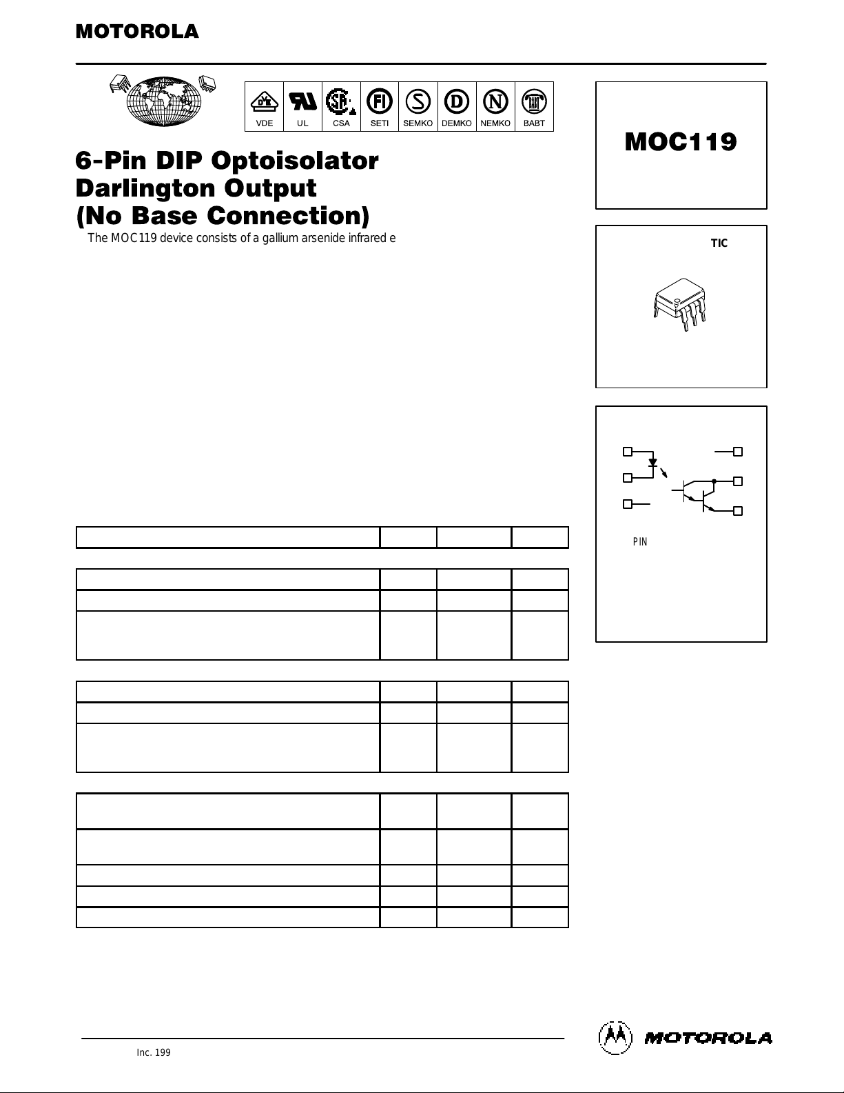
The MOC119 device c onsists of a g allium arsenide i nfrared emitting d iode o ptically
coupled to a monolithic silicon photodarlington detector. The chip to Pin 6 connection
has been eliminated for better performance when used in high noise environments.
It is designed for use in applications requiring high improved noise immunity.
• Provides Higher Output Collector Current (
IC) with Lower Values of Input Drive Current (IF)
•
To order devices that are tested and marked per VDE 0884 requirements, the
suffix ”V” must be included at end of part number. VDE 0884 is a test option.
Applications
• Appliance, Measuring Instruments
• Interfacing and coupling systems of different potentials and impedances
• Monitor and Detection Circuits
• I/O Interfaces for Computers
• Solid State Relays
• Portable Electronics
• Programmable Controllers
MAXIMUM RATINGS
(TA = 25°C unless otherwise noted)
Rating
Symbol Value Unit
INPUT LED
Reverse Voltage V
R
3 Volts
Forward Current — Continuous I
F
60 mA
LED Power Dissipation @ TA = 25°C
with Negligible Power in Output Detector
Derate above 25°C
P
D
120
1.41
mW
mW/°C
OUTPUT DETECTOR
Collector–Emitter Voltage V
CEO
30 Volts
Emitter–Collector Voltage V
ECO
7 Volts
Detector Power Dissipation @ TA = 25°C
with Negligible Power in Input LED
Derate above 25°C
P
D
150
1.76
mW
mW/°C
TOTAL DEVICE
Isolation Surge Voltage
(1)
(Peak ac Voltage, 60 Hz, 1 sec Duration)
V
ISO
7500 Vac(pk)
Total Device Power Dissipation @ TA = 25°C
Derate above 25°C
P
D
250
2.94
mW
mW/°C
Ambient Operating Temperature Range
(2)
T
A
–55 to +100 °C
Storage Temperature Range
(2)
T
stg
–55 to +150 °C
Soldering Temperature (10 sec, 1/16″ from case) T
L
260 °C
1. Isolation surge voltage is an internal device dielectric breakdown rating.
1. For this test, Pins 1 and 2 are common, and Pins 4 and 5 are common.
2. Refer to Quality and Reliability Section in Opto Data Book for information on test conditions.
GlobalOptoisolator is a trademark of Motorola, Inc.
Order this document
by MOC119/D
SEMICONDUCTOR TECHNICAL DATA
GlobalOptoisolator
Motorola, Inc. 1995
SCHEMATIC
[CTR = 300% Min]
STANDARD THRU HOLE
CASE 730A–04
STYLE 3 PLASTIC
PIN 1. LED ANODE
2. LED CATHODE
3. N.C.
4. EMITTER
5. COLLECTOR
6. N.C.
1
2
3
6
5
4
6
1
REV 2
MOC119
2
Motorola Optoelectronics Device Data
ELECTRICAL CHARACTERISTICS
(TA = 25°C unless otherwise noted)
(1)
Characteristic Symbol Min Typ
(1)
Max Unit
INPUT LED
Reverse Leakage Current
(VR = 3 V)
I
R
— 0.05 100 µA
Forward Voltage
(IF = 10 mA)
V
F
— 1.15 1.5 Volts
Capacitance
(VR = 0 V, f = 1 MHz)
C — 18 — pF
PHOTOTRANSISTOR (TA = 25°C and IF = 0 unless otherwise noted)
Collector–Emitter Dark Current
(VCE = 10 V)
I
CEO
— — 100 nA
Collector–Emitter Breakdown Voltage
(IC = 100 µA)
V
(BR)CEO
30 — — Volts
Emitter–Collector Breakdown Voltage
(IE = 10 µA)
V
(BR)ECO
7 — — Volts
COUPLED (TA = 25°C unless otherwise noted)
Collector Output Current
(3)
(VCE = 2 V, IF = 10 mA)
IC (CTR)
(2)
30 (300) 45 (450) — mA (%)
Isolation Surge Voltage
(4,5)
, 60 Hz ac Peak, 1 Second V
ISO
7500 — — Vac(pk)
Isolation Resistance
(4)
(V = 500 V)
R
ISO
— 10
11
— Ohms
Collector–Emitter Saturation Voltage
(3)
(IC = 10 mA, IF = 10 mA)
V
CE(sat)
— — 1 Volt
Isolation Capacitance
(4)
(V = 0 V, f = 1 MHz)
C
ISO
— 0.2 — pF
SWITCHING (Figures 4, 5)
Turn–On Time
t
on
— 3.5 —
µs
Turn–Off Time
t
off
— 95 —
Rise Time
VCE = 10 V, RL = 100 Ω, IF = 5 mA
(6)
t
r
— 1 —
Fall Time t
f
— 2 —
1. Always design to the specified minimum/maximum electrical limits (where applicable).
2. Current Transfer Ratio (CTR) = IC/IF x 100%.
3. Pulse Test: Pulse Width = 300 µs, Duty Cycle p2%.
4. For this test, LED Pins 1 and 2 are common and Phototransistor Pins 4 and 5 are common.
5. Isolation Surge Voltage, V
ISO
, is an internal device dielectric breakdown rating.
6. For test circuit setup and waveforms, refer to Figure 9.
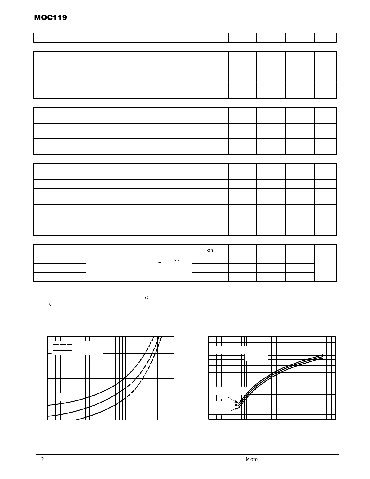
TYPICAL CHARACTERISTICS
TA = 25°C
TA = –55°C THRU
+70°C
+100°C
+25°C
Figure 1. LED Forward Voltage versus Forward Current Figure 2. Output Current versus Input Current
2
1.8
1.6
1.4
1.2
1
1 10 100 1000
IF, LED FORWARD CURRENT (mA)
25°C
100°C
V
F
, FORWARD VOLTAGE (VOLTS)
I
C
, OUTPUT COLLECTOR CURRENT (NORMALIZED)
10
1
0.1
0.01
0.5 1 2 5 10 20 50
IF, LED INPUT CURRENT (mA)
NORMALIZED TO: IF = 10 mA
TA = –55°C
PULSE ONLY
PULSE OR DC
 Loading...