

Motorola MC74F153D, MC74F153N, MC54F153N Datasheet
4-64
FAST AND LS TTL DATA
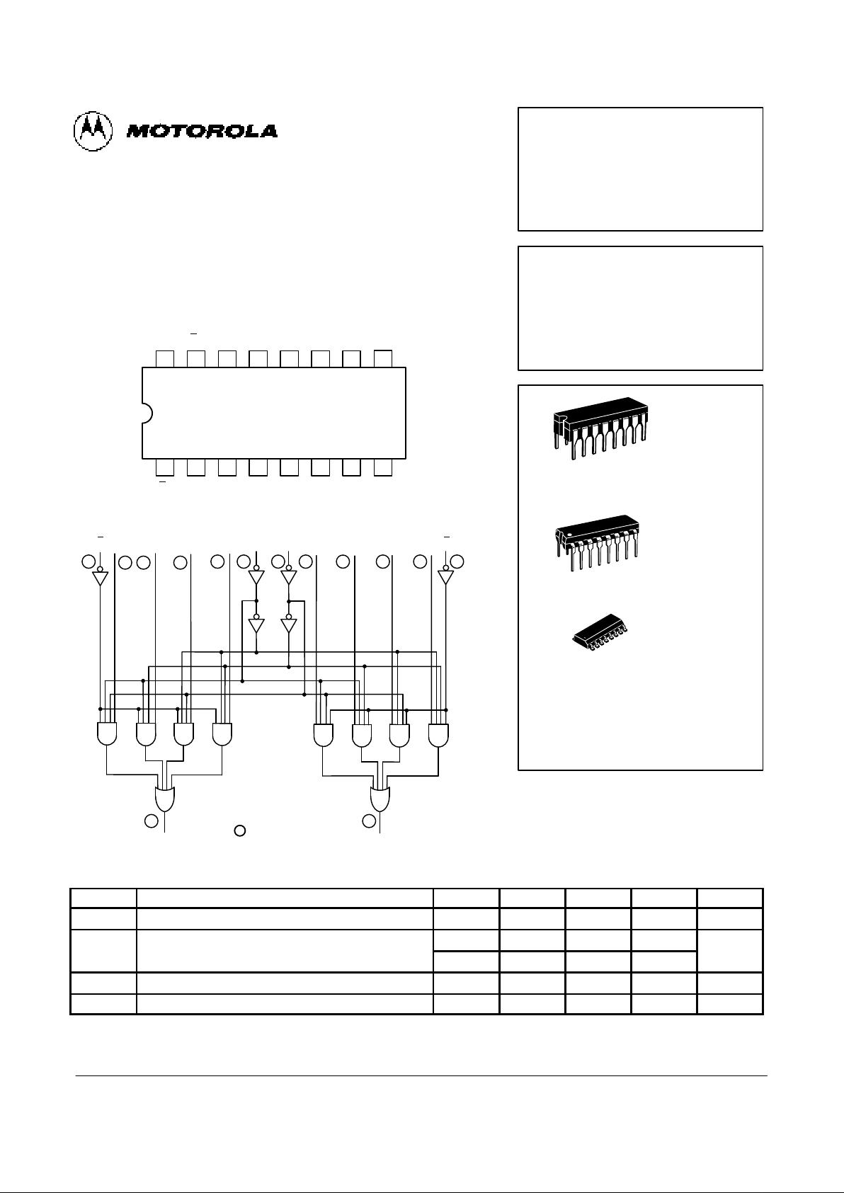
DUAL 4-INPUT MULTIPLEXER
The MC54/74F153 is a high-speed Dual 4-Input Multiplexer with common
select inputs and individual enable inputs for each section. It can select two
lines of data from four sources. The two buffered outputs present data in the
true (non-inverted) form. In addition to multiplexer operation, the F153 can
generate any two functions of three variables.
CONNECTION DIAGRAM DIP (TOP VIEW)
1516 14 13 12 11 10
21 3 4 5 6 7
V
CC
9
8
E
bS0I3bI2bI1b
I
0bZb
E
aS1I3aI2aI1aI0aZa
GND
LOGIC DIAGRAM
VCC = PIN 16
GND = PIN 8
= PIN NUMBERS
E
b
E
a
Z
a
Z
b
I
0aI1aI2aI3aS1S0I0bI1bI2b
I
3b
6 5
1 23
4
10 11 12 1314 15
7
9
GUARANTEED OPERATING RANGES
Symbol Parameter Min Typ Max Unit
V
CC
Supply Voltage 54, 74 4.5 5.0 5.5 V
T
A
Operating Ambient Temperature Range 54 –55 25 125 °C
74 0 25 70
I
OH
Output Current — High 54, 74 –1.0 mA
I
OL
Output Current — Low 54, 74 20 mA
MC54FXXXJ Ceramic
MC74FXXXN Plastic
MC74FXXXD SOIC
MC54/74F153
DUAL 4-INPUT
MULTIPLEXER
FAST SHOTTKY TTL
J SUFFIX
CERAMIC
CASE 620-09
N SUFFIX
PLASTIC
CASE 648-08
16
1
16
1
ORDERING INFORMATION
16
1
D SUFFIX
SOIC
CASE 751B-03
4-65
FAST AND LS TTL DATA
MC54/74F153
FUNCTIONAL DESCRIPTION
The MC54/74F153 is a Dual 4-Input Multiplexer. It can select two bits of data from up to four sources under the control
of the common Select Inputs (S0, S1). The two 4-input multiplexer circuits have individual active LOW Enables (Ea, Eb)
which can be used to strobe the outputs independently. When
the Enables (E
a
, Eb) are HIGH, the corresponding outputs (Za,
Zb) are forced LOW.
The F153 is the logic implementation of a 2-pole, 4-position
switch, where the position of the switch is determined by the
logic levels supplied to the two Select Inputs. The logic equations for the outputs are shown below:
Za = E
a
• (I0a • S1 • S0 + I1a • S1 • S0 +
I2a • S1 • S
0
+ I3a • S1 • S0)
Zb = E
b
• (I0b • S1 • S0 + I1b • S1 • S0 +
I2b • S1 • S
0
+ I3b • S1 • S0)
The F153 can be used to move data from a group of registers to a common output bus. The particular register from
which the data came would be determined by the state of the
Select Inputs. A less obvious application is as a function generator. The F153 can generate two functions of three variables. This is useful for implementing highly irregular random
logic.
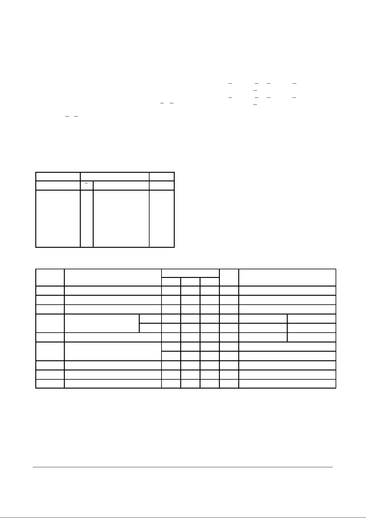
FUNCTION TABLE
Select Inputs Inputs (a or b) Output
S
0
S
1
E I
0I1I2I3
Z
X X H X X X X L
L L L L X X X L
L L L H X X X H
H L L X L X X L
H L L X H X X H
L H L X X L X L
L H L X X H X H
H H L X X X L L
H H L X X X H H
H = HIGH Voltage Level; L = LOW Voltage Level; X = Don’t Care
DC CHARACTERISTICS OVER OPERATING TEMPERATURE RANGE (unless otherwise specified)
Limits
Symbol Parameter Min Typ Max Unit Test Conditions
V
IH
Input HIGH Voltage 2.0 V Guaranteed Input HIGH Voltage
V
IL
Input LOW Voltage 0.8 V Guaranteed Input LOW Voltage
V
IK
Input Clamp Diode Voltage –1.2 V IIN = –18 mA, VCC = MIN
V
OH
Output HIGH Voltage
54, 74 2.5 V IOL = –1.0 mA VCC = 4.50V
74 2.7 V IOL = –1.0 mA VCC = 4.75 V
V
OL
Output LOW Voltage 0.5 V IOL = 20 mA VCC = MIN
I
IH
Input HIGH Current 20
µA VIN = 2.7 V, VCC = MAX
0.1 mA VIN = 7.0 V, VCC = MAX
I
IL
Input LOW Current –0.6 mA VIN = 0.5 V, VCC = MAX
I
OS
Output Short Circuit Current (Note 2) –60 –150 mA V
OUT
= 0 V, VCC = MAX
I
CC
Power Supply Current 20 mA VIN = GND, VCC = MAX
NOTES:
1. For conditions shown as MIN or MAX, use the appropriate value specified under recommended operating conditions for the applicable device type.
2. Not more than one output should be shorted at a time, nor for more than 1 second.
 Loading...