

4-59
FAST AND LS TTL DATA
8-LINE TO 3-LINE
PRIORITY ENCODER
The MC54/74F148 provides three bits of binary coded output representing
the position of the highest order active input, along with an output indicating
the presence of any active input. It is easily expanded via input and output enables to provide priority encoding over many bits.
• Encodes Eight Data Lines in Priority
• Provides 3-Bit Binary Priority Code
• Input Enable Capability
• Signals When Data Present on Any Input
• Cascadable for Priority Encoding of n Bits
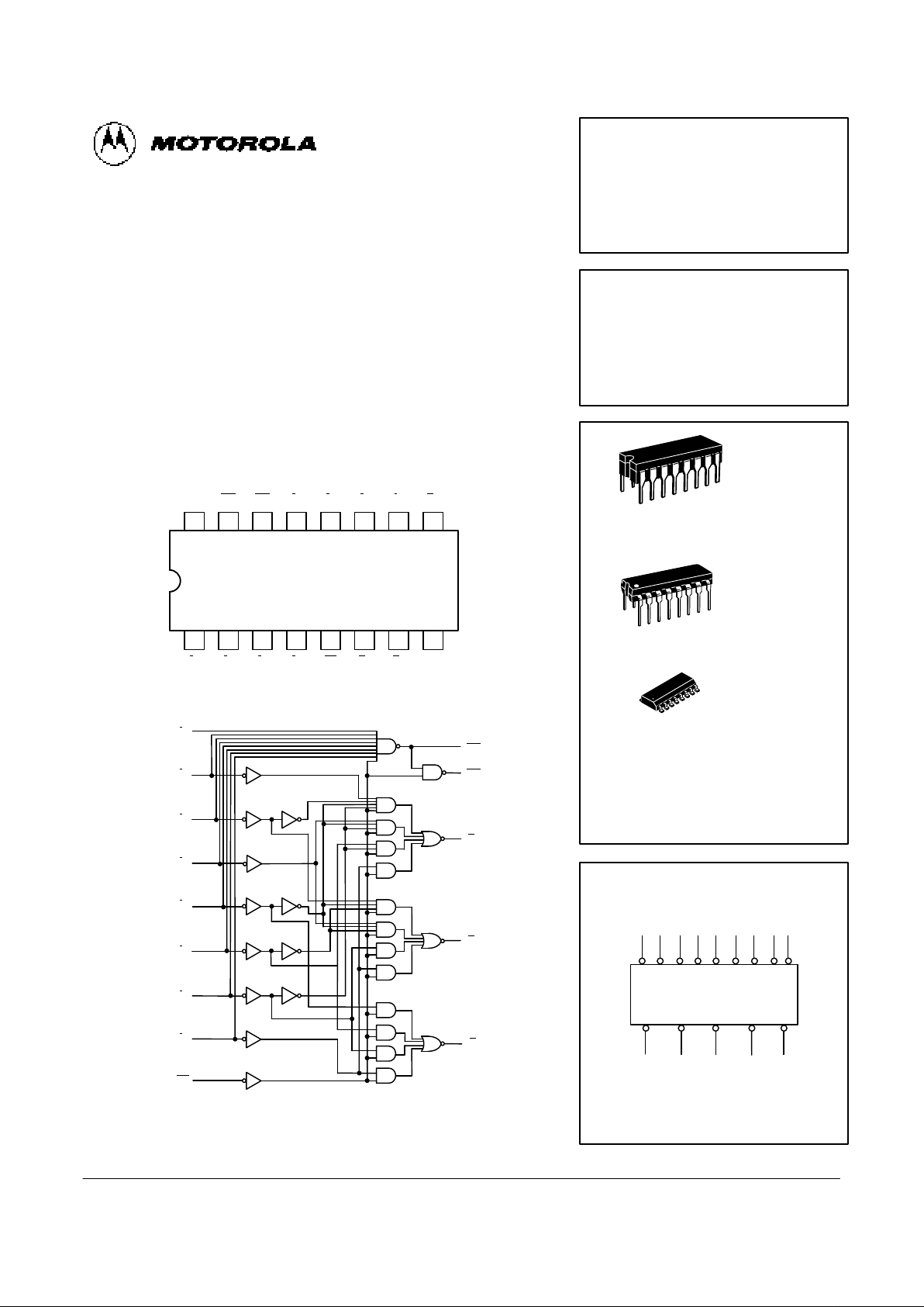
CONNECTION DIAGRAM DIP (TOP VIEW)
1516 14 13 12 11 10
21 3 4 5 6 7
V
CC
9
8
EO GS I
3I2I1I0A0
I4I5I6I7E1
A
2A1
GND
NOTE:
This diagram is provided only for the understanding of logic operations and should not
be used to estimate propagation delays.
LOGIC DIAGRAM
I
0
I
1
I
2
I
3
I
4
I
5
I
6
I
7
E1
EO
GS
A
0
A
1
A
2
(10)
(11)
(12)
(13)
(1)
(2)
(3)
(4)
(5)
(15)
(14)
(9)
(7)
(6)
MC54FXXXJ Ceramic
MC74FXXXN Plastic
MC74FXXXD SOIC
MC54/74F148
8-LINE TO 3-LINE
PRIORITY ENCODER
FAST SHOTTKY TTL
J SUFFIX
CERAMIC
CASE 620-09
N SUFFIX
PLASTIC
CASE 648-08
16
1
16
1
ORDERING INFORMATION
16
1
D SUFFIX
SOIC
CASE 751B-03
LOGIC SYMBOL
I0I1I2I3I4I5I6I7E1
EO A0A1A2GS
5432113121110
1467915
VCC = PIN 16
GND = PIN 8
4-60
FAST AND LS TTL DATA
MC54/74F148
GUARANTEED OPERATING RANGES
Symbol Parameter Min Typ Max Unit
V
CC
Supply Voltage 54, 74 4.5 5.0 5.5 V
T
A
Operating Ambient Temperature Range
54 –55 25 125
°C
74 0 25 70
I
OH
Output Current — High 54, 74 –1.0 mA
I
OL
Output Current — Low 54, 74 20 mA
FUNCTIONAL DESCRIPTION
The F148 8-input priority encoder accepts data from eight
active LOW inputs (I
0–I7
) and provides a binary representation on the three active LOW outputs. A priority is assigned to
each input so that when two or more inputs are simultaneously
active, the input with the highest priority is represented on the
output, with input line 7 having the highest priority. A HIGH on
the Enable Input (E1
) will force all outputs to the inactive
(HIGH) state and allow new data to settle without producing
erroneous information at the outputs. A Group Signal output
(GS
) and Enable Output (EO) are provided along with the
three priority data outputs (A
2
, A1, A0). GS
is active LOW when
any input is LOW; this indicates when any input is active. EO
is active LOW when all inputs are HIGH. Using the Enable
Output along with the Enable Input allows cascading for priority encoding on any number of input signals. Both EO
and GS
are in the inactive HIGH state when the Enable Input is HIGH.
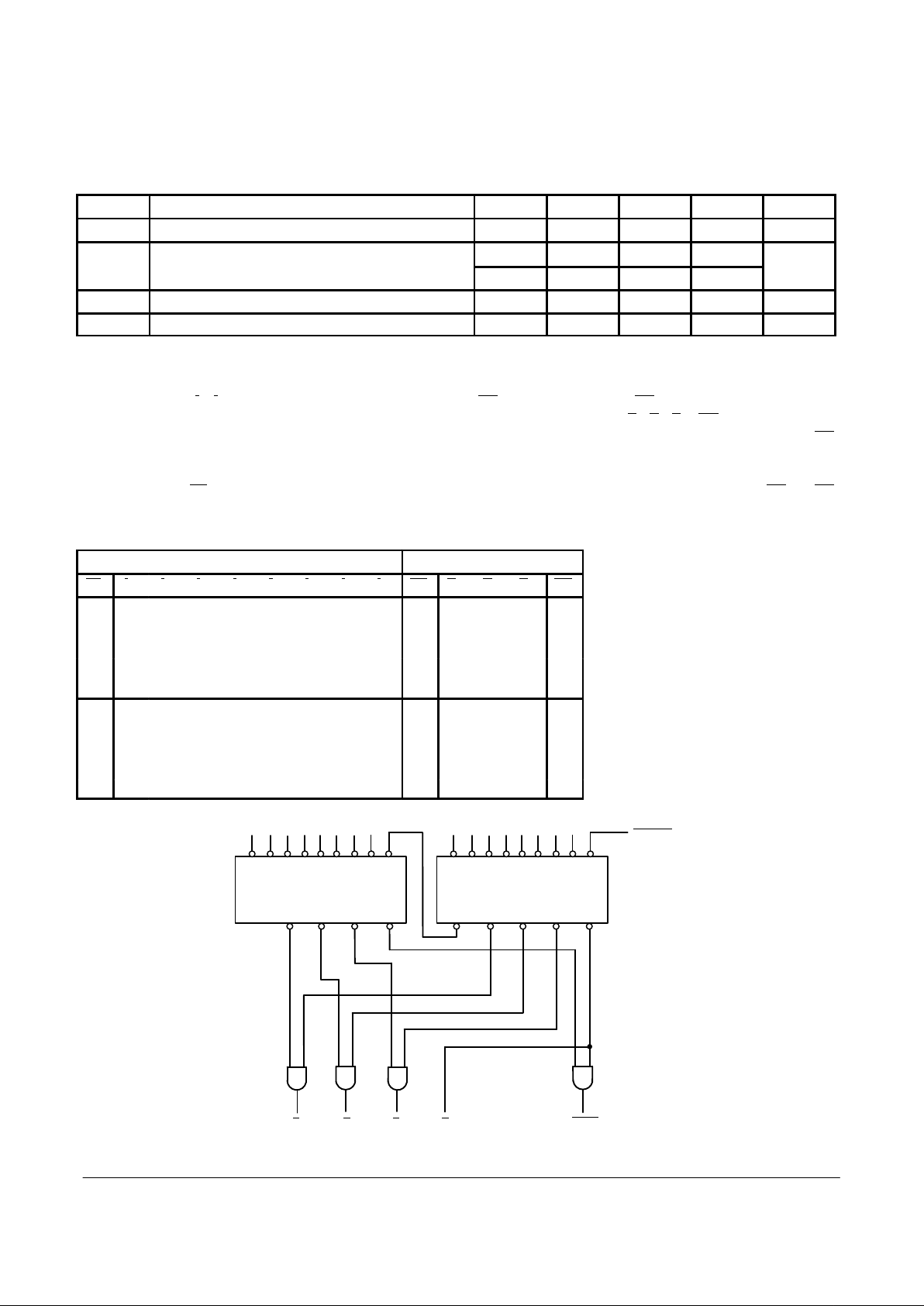
FUNCTION TABLE
Inputs Outputs
E1 I
0I1I2I3I4I5I6I7
GS A0A1A2EO
H X X X X X X X X H H H H H
L H H H H H H H H H H H H L
L X X X X X X X L L L L L H
L X X X X X X L H L H L L H
L X X X X X L H H L L H L H
L X X X X L H H H L H H L H
L X X X L H H H H L L L H H
L X X L H H H H H L H L H H
L X L H H H H H H L L H H H
L L H H H H H H H L H H H H
H = HIGH Voltage Level; L = LOW Voltage Level; X = Don’t Care
0 1 2 3 4 5 6 7 E1
A
2
A
1
A
0
GS
’F148
ENABLE
MSB
LSB
FLAG
A
3
A
2
A
1
A
0
0 1 2 3 4 5 6 7 E1
A
2
A
1
A
0
GS
’F148 ’F148
Figure 1. Application: 16-Input Priority Encoder
EO
 Loading...