

Motorola MC74F138D, MC74F138N, MC54F138J Datasheet
4-53
FAST AND LS TTL DATA
1-OF-8 DECODER/
DEMULTIPLEXER
The MC54/74F138 is a high speed 1-of-8 Decoder/Demultiplexer. This device is ideally suited for high speed bipolar memory chip select address decoding. The multiple input enables allow parallel expansion to a 1-of-24 decoder using just three F138 devices or to a 1-of-32 decoder using four F138s
and one inverter.
• Demultiplexing Capability
• Multiple Input Enable for Easy Expansion
• Active Low Mutually Exclusive Outputs
• Input Clamp Diodes Limit High-Speed Termination Effects
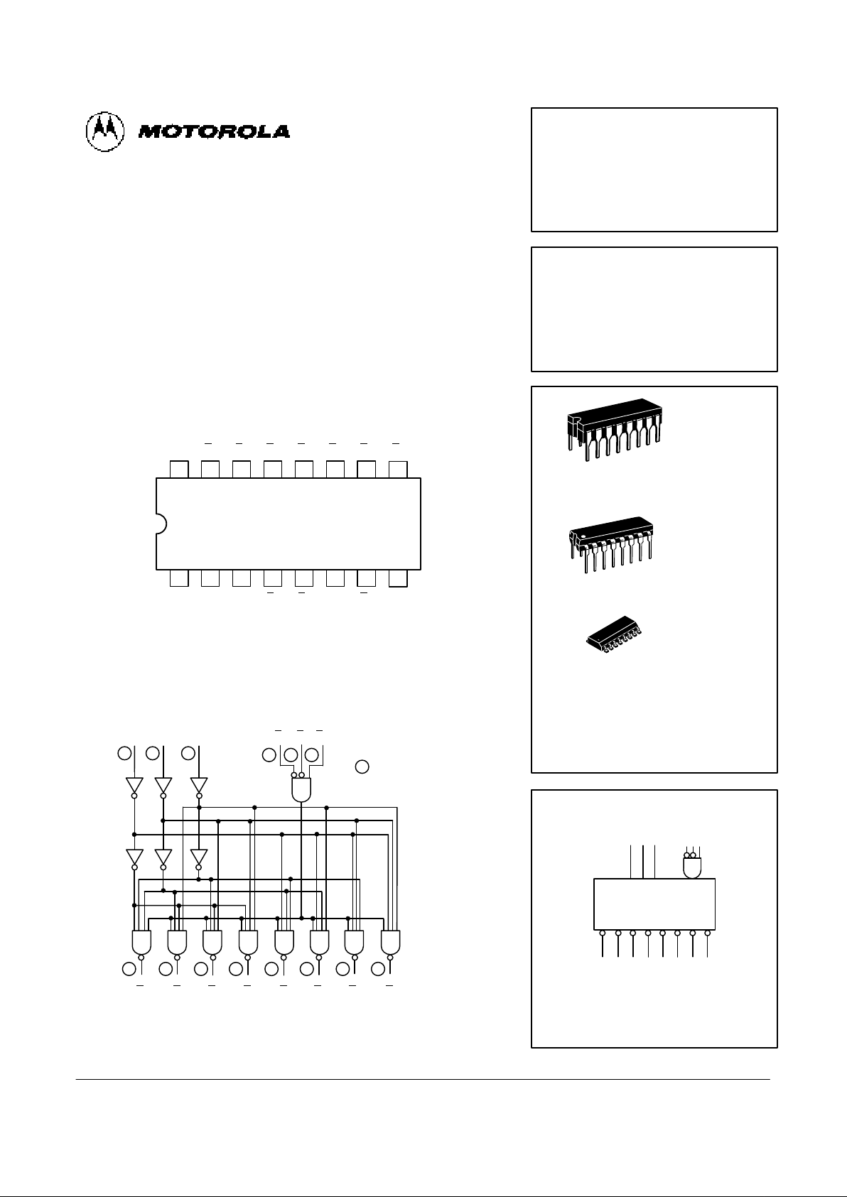
CONNECTION DIAGRAM DIP (TOP VIEW)
1516 14 13 12 11 10
21 3 4 5 6 7
V
CC
9
8
O
0O1O2O3O4O5O6
A0A1A2E1E2E3O7GND
6
5
LOGIC DIAGRAM
VCC = PIN 16
GND = PIN 8
= PIN NUMBERS
3
A2A
1
A
0
E
1E2E3
O
7
O5O4O3O2O
1
O
0
O
6
2 1
4
7
9 10 11
12
13 14
15
4 5 6
1 2 3
MC54FXXXJ Ceramic
MC74FXXXN Plastic
MC74FXXXD SOIC
MC54/74F138
1-OF-8 DECODER/
DEMULTIPLEXER
FAST SHOTTKY TTL
J SUFFIX
CERAMIC
CASE 620-09
N SUFFIX
PLASTIC
CASE 648-08
16
1
16
1
ORDERING INFORMATION
16
1
D SUFFIX
SOIC
CASE 751B-03
LOGIC SYMBOL
VCC = PIN 16
GND = PIN 8
1 2 3
O0 O1 O2 O3 O4 O5 O6 O
7
15 14 13 12 11 10 9 7
A0 A1 A
2
4-54
FAST AND LS TTL DATA
MC54/74F138
GUARANTEED OPERATING RANGES
Symbol Parameter Min Typ Max Unit
V
CC
Supply Voltage 54, 74 4.5 5.0 5.5 V
T
A
Operating Ambient Temperature Range 54 –55 25 125 °C
74 0 25 70
I
OH
Output Current — High 54, 74 –1.0 mA
I
OL
Output Current — Low 54, 74 20 mA
DC CHARACTERISTICS OVER OPERATING TEMPERATURE RANGE (unless otherwise specified)
Limits
Symbol Parameter Min Typ Max Unit Test Conditions
V
IH
Input HIGH Voltage 2.0 V Guaranteed Input HIGH Voltage
V
IL
Input LOW Voltage 0.8 V Guaranteed Input LOW Voltage
V
IK
Input Clamp Diode Voltage –1.2 V VCC = MIN, IIN = –18 mA
V
OH
Output HIGH Voltage 54, 74 2.5 V IOH = –1.0 mA VCC = 4.50 V
74 2.7 V IOH = –1.0 mA VCC = 4.75 V
V
OL
Output LOW Voltage 0.5 V IOL = 20 mA VCC = MIN
I
IH
Input HIGH Current 20 µA VCC = MAX, VIN = 2.7 V
0.1 mA VCC = MAX, VIN = 7.0 V
I
IL
Input LOW Current –0.6 mA VCC = MAX, VIN = 0.5 V
I
OS
Output Short Circuit Current (Note 2) –60 –150 mA VCC = MAX, V
OUT
= 0 V
I
CC
Power Supply Current 20 mA VCC = MAX
NOTES:
1. For conditions shown as MIN or MAX, use the appropriate value specified under recommended operating conditions for the applicable device type.
2. Not more than one output should be shorted at a time, nor for more than 1 second.
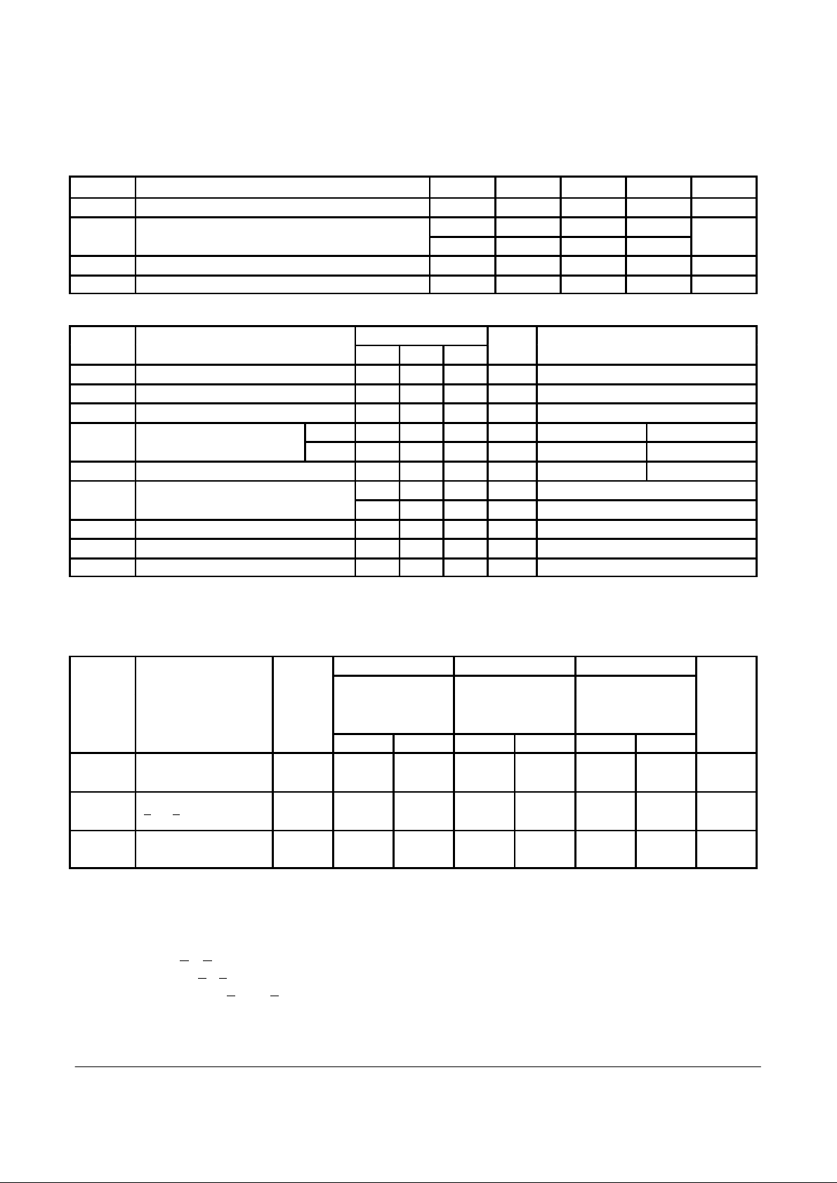
AC CHARACTERISTICS
54/74F 54F 74F
TA = +25 °C TA = +25°C to +125°C TA = 0°C to 70°C
Levels
VCC = +5.0 V VCC = 5.0 V ±10% VCC = 5.0 V ±10%
of
CL = 50 pF CL = 50 pF CL = 50 pF
Symbol Parameter
Delay
Min Max Min Max Min Max Unit
t
PLH
Propagation Delay,
3
3.0 7.5 3.0 12 3.0 8.5 ns
t
PHL
Address to Output 3.0 8.0 3.0 9.5 3.0 9.0
t
PLH
Enable to Output
2
3.5 7.0 3.5 11 3.5 8.0 ns
t
PHL
E
1
or E
2
3.0 7.0 3.0 8.0 3.0 7.5
t
PLH
Enable to Output
3
4.0 8.0 4.0 12.5 4.0 9.0 ns
t
PHL
E3 3.5 7.5 3.5 8.5 3.5 8.5
FUNCTIONAL DESCRIPTION
The decoder accepts three binary weighted inputs (AO, A1,
A2) and when enabled provides eight mutually exclusive
active LOW outputs (O
0–O7
). The F138 features three Enable
inputs, two active LOW (E
1
, E2) and one active HIGH (E3). All
outputs will be HIGH unless E
1
and E2 are LOW and E3 is
HIGH. This multiple enable function allows easy parallel
expansion of the device to a 1-of-32 (5 lines to 32 lines)
decoder with just four F138s and one inverter.
The F138 can be used as an 8-output demultiplexer by
using one of the active LOW Enable inputs as the data input
and the other Enable inputs as strobes. The Enable inputs
which are not used must be permanently tied to their
appropriate active HIGH or active LOW states.
 Loading...