

Page 1

MC7090CN Enterprise Digital
Assistant
User Guide
Page 2

Page 3

MC7090CN
User Guide
72E-88965-03
Revision A
March 2015
Page 4

ii MC7090CN User Guide
© 2015 ZIH Corp and/or its affiliates. All rights reserved.
No part of this publication may be reproduced or used in any form, or by any electrical or mechanical means,
without permission in writing from Zebra. This includes electronic or mechanical means, such as photocopying,
recording, or information storage and retrieval systems. The material in this manual is subject to change
without notice.
The software is provided strictly on an “as is” basis. All software, including firmware, furnished to the user is on
a licensed basis. Zebra grants to the user a non-transferable and non-exclusive license to use each software
or firmware program delivered hereunder (licensed program). Except as noted below, such license may not be
assigned, sublicensed, or otherwise transferred by the user without prior written consent of Zebra. No right to
copy a licensed program in whole or in part is granted, except as permitted under copyright law. The user shall
not modify, merge, or incorporate any form or portion of a licensed program with other program material, create
a derivative work from a licensed program, or use a licensed program in a network without written permission
from Zebra. The user agrees to maintain Zebra’s copyright notice on the licensed programs delivered
hereunder, and to include the same on any authorized copies it makes, in whole or in part. The user agrees not
to decompile, disassemble, decode, or reverse engineer any licensed program delivered to the user or any
portion thereof.
Zebra reserves the right to make changes to any software or product to improve reliability, function, or design.
Zebra does not assume any product liability arising out of, or in connection with, the application or use of any
product, circuit, or application described herein.
No license is granted, either expressly or by implication, estoppel, or otherwise under any Zebra, intellectual
property rights. An implied license only exists for equipment, circuits, and subsystems contained in Zebra
products.
Warranty
For the complete Zebra hardware product warranty statement, go to: http://www.zebra.com/warranty.
Page 5

Table of Contents
About This Guide
Introduction .................................................................................................................... vii
Documentation Set .................................................................................................. vii
Configurations................................................................................................................ viii
Chapter Descriptions ..................................................................................................... viii
Notational Conventions.................................................................................................. ix
Related Documents ....................................................................................................... x
Service Information........................................................................................................ x
Chapter 1: Getting Started
Introduction ................................................................................................................... 1-1
Unpacking ..................................................................................................................... 1-2
Accessories ................................................................................................................... 1-3
Getting Started .............................................................................................................. 1-4
Installing and Removing the Main Battery .................................................................... 1-4
Installing the Main Battery ....................................................................................... 1-4
Removing the Main Battery ..................................................................................... 1-5
Charging the Battery ..................................................................................................... 1-6
Charging the Main Battery and Memory Backup Battery ........................................ 1-6
Charging Spare Batteries ........................................................................................ 1-7
Charging Temperature ............................................................................................ 1-8
Powering On the EDA ................................................................................................... 1-8
Calibrating the Screen ............................................................................................ 1-8
Checking Battery Status ............................................................................................... 1-8
Adjusting the Handstrap ................................................................................................ 1-8
Removing the Screen Protector .................................................................................... 1-10
Battery Management ..................................................................................................... 1-10
Changing the Power Settings ................................................................................. 1-11
Changing the Backlight Settings ............................................................................. 1-11
Changing the Keypad Backlight Settings ................................................................ 1-11
Turning Off the Radios ............................................................................................ 1-11
Turning Off the WLAN Radio ............................................................................ 1-11
Turning Off the Bluetooth and WAN Radios ..................................................... 1-12
Chapter 2: Using the MC70
Introduction ................................................................................................................... 2-1
Page 6

iv MC7090CN User Guide
Status Icons .................................................................................................................. 2-1
Speaker Icon ........................................................................................................... 2-2
Battery Icon ............................................................................................................. 2-3
Connectivity Icon ..................................................................................................... 2-3
Time Icon ................................................................................................................ 2-4
Multiple Notifications Icon ....................................................................................... 2-5
LED Indicators .............................................................................................................. 2-5
Keypads ........................................................................................................................ 2-6
Numeric Keypad Configuration ............................................................................... 2-6
QWERTY Keypad Configuration ............................................................................. 2-10
Special Character Key ...................................................................................... 2-14
Function Buttons ........................................................................................................... 2-16
Stylus ............................................................................................................................ 2-16
Data Capture ................................................................................................................ 2-17
Linear Scanning ...................................................................................................... 2-17
Imaging ................................................................................................................... 2-17
Operational Modes ............................................................................................ 2-17
Scanning Considerations ........................................................................................ 2-18
Linear Scanning ...................................................................................................... 2-18
Imager Scanning ..................................................................................................... 2-19
Resetting the EDA ........................................................................................................ 2-20
Performing a Warm Boot ........................................................................................ 2-20
Performing a Cold Boot ........................................................................................... 2-20
Waking the EDA ...................................................................................................... 2-21
Locking the EDA ........................................................................................................... 2-21
Chapter 3: Using Bluetooth
Introduction ................................................................................................................... 3-1
Adaptive Frequency Hopping ....................................................................................... 3-1
Security ......................................................................................................................... 3-2
Turning the Bluetooth Radio Mode On and Off ............................................................ 3-2
Disabling Bluetooth ................................................................................................. 3-3
Enabling Bluetooth .................................................................................................. 3-3
Bluetooth Power States .......................................................................................... 3-3
Cold Boot .......................................................................................................... 3-3
Warm Boot ........................................................................................................ 3-4
Suspend ............................................................................................................ 3-4
Resume ............................................................................................................. 3-4
Modes ........................................................................................................................... 3-4
Wizard Mode ........................................................................................................... 3-4
Explorer Mode ......................................................................................................... 3-6
Discovering Bluetooth Device(s) ................................................................................... 3-7
Bonding with Discovered Device(s) .................................................................. 3-8
Renaming a Bonded Device ............................................................................. 3-10
Deleting a Bonded Device ................................................................................ 3-11
Accepting a Bond .............................................................................................. 3-12
Discovering Services .................................................................................................... 3-12
File Transfer Services ............................................................................................. 3-13
Page 7

Table of Contents - v
Creating a New File or Folder ........................................................................... 3-14
Deleting a File ................................................................................................... 3-14
Getting a File ..................................................................................................... 3-14
Copying a File ................................................................................................... 3-15
Connecting to the Internet Using an Access Point .................................................. 3-15
Dial-Up Networking Services .................................................................................. 3-15
Adding a Dial-up Entry ...................................................................................... 3-18
Object Exchange Push Services ............................................................................. 3-19
Sending a Contact ............................................................................................. 3-19
Sending a Picture .............................................................................................. 3-20
Serial Port Services ................................................................................................ 3-21
ActiveSync Using Serial Port Services .............................................................. 3-22
Personal Area Network Services ............................................................................ 3-23
Bluetooth Settings ......................................................................................................... 3-24
Device Info Tab ....................................................................................................... 3-24
Services Tab ........................................................................................................... 3-24
Dial-Up Networking Service .............................................................................. 3-25
File Transfer Service ......................................................................................... 3-26
OBEX Object Push Service ............................................................................... 3-26
Personal Area Networking Service ................................................................... 3-27
Serial Port Service ............................................................................................ 3-27
Security Tab ............................................................................................................ 3-28
Discovery Tab ......................................................................................................... 3-29
Virtual COM Port Tab .............................................................................................. 3-29
Miscellaneous Tab .................................................................................................. 3-30
Chapter 4: Accessories
Introduction ................................................................................................................... 4-1
Cables ..................................................................................................................... 4-1
Cradles .................................................................................................................... 4-1
Miscellaneous ......................................................................................................... 4-1
Snap-on Modules .................................................................................................... 4-1
Multi Media Card (MMC) / Secure Digital (SD) Card .................................................... 4-2
Single Slot USB/Serial Cradle ....................................................................................... 4-3
Charging the EDA Battery ....................................................................................... 4-3
Charging the Spare Battery .................................................................................... 4-4
Battery Charging Indicators .................................................................................... 4-4
Charging Temperature ...................................................................................... 4-4
Four Slot Ethernet Cradle ............................................................................................. 4-5
Charging ................................................................................................................ 4-5
Battery Charging Indicators .................................................................................... 4-5
Charging Temperature ...................................................................................... 4-6
VCD7000 Vehicle Cradle .............................................................................................. 4-6
Charging the EDA Battery ....................................................................................... 4-6
Removing the EDA ............................................................................................ 4-7
Charging the Spare Battery .................................................................................... 4-7
Battery Charging Indicators .................................................................................... 4-8
Charging Temperature ...................................................................................... 4-8
Page 8

vi MC7090CN User Guide
Four Slot Spare Battery Charger .................................................................................. 4-9
MC70 Battery Shim Installation ............................................................................... 4-9
Spare Battery Charging .......................................................................................... 4-10
Battery Charging Indicators .................................................................................... 4-10
Charging Temperature ...................................................................................... 4-10
Magnetic Stripe Reader (MSR) ..................................................................................... 4-11
Attaching and Removing the MSR .......................................................................... 4-11
Using the MSR ....................................................................................................... 4-12
TRG7000 Trigger Handle ............................................................................................. 4-12
Inserting the EDA into the Trigger Handle .............................................................. 4-13
Removing the EDA ................................................................................................. 4-13
Scanning ................................................................................................................. 4-13
Using a Cradle ........................................................................................................ 4-14
Cables ........................................................................................................................... 4-15
Battery Charging and Operating Power .................................................................. 4-16
LED Charge Indications .......................................................................................... 4-16
Charging Temperature ...................................................................................... 4-16
Chapter 5: Maintenance & Troubleshooting
Introduction ................................................................................................................... 5-1
Maintaining the EDA ..................................................................................................... 5-1
Troubleshooting ............................................................................................................ 5-2
EDA ......................................................................................................................... 5-2
Bluetooth Connection .............................................................................................. 5-4
Single Slot USB/Serial Cradle ................................................................................. 5-6
Four Slot Ethernet Cradle ....................................................................................... 5-7
Vehicle Cradle ......................................................................................................... 5-8
Four Slot Spare Battery Charger ............................................................................ 5-9
Cables ..................................................................................................................... 5-10
Magnetic Stripe Reader .......................................................................................... 5-10
Trigger Handle .............................................................................................................. 5-11
Appendix A: Technical Specifications
MC7090CN Technical Specifications ........................................................................... A-1
MC7090CN Accessory Specifications .......................................................................... A-4
Page 9

About This Guide
Introduction
This guide provides information about using the MC7090CN Enterprise Digital Assistant (EDA) and
accessories.
NOTE Screens and windows pictured in this guide are samples and can differ from actual screens.
Documentation Set
The documentation set for the MC7090CN provides information for specific user needs, and includes:
•
Microsoft® Windows Mobile 5.0 Applications User Guide for Zebra Devices - describes how to use
Microsoft developed applications.
About This Guide
•
Application Guide - describes how to use Zebra developed sample applications.
•
MC7090CN User Guide - describes how to use the MC7090CN EDA.
•
MC7090CN Integrator Guide - describes how to set up the MC7090CN EDA and accessories.
•
SMDK Help File - provides API information for writing applications.
Page 10

viii MC7090CN User Guide
Configurations
This guide covers the following configurations:
•
MC7090CN - Windows® Mobile 5.0 Operating System; 802.11a/b/g radio; Bluetooth® wireless
technology; color display; 64MB RAM/128MB flash memory; 1D laser scanner or 2D imager; numeric or
QWERTY keypad; user accessible SD card slot.
Chapter Descriptions
Topics covered in this guide are as follows:
•
Chapter 1, Getting Started provides information on getting the EDA up and running for the first time.
•
Chapter 2, Using the MC70 provides basic instructions for using the EDA, including powering on and
resetting the EDA, and entering and capturing data.
•
Chapter 3, Using Bluetooth explains Bluetooth functionality on the EDA.
•
Chapter 4, Accessories describes the available accessories and how to use them with the EDA.
Page 11

•
Chapter 5, Maintenance & Troubleshooting includes instructions on cleaning and storing the EDA, and
provides troubleshooting solutions for potential problems during EDA operation.
•
Appendix A, Technical Specifications provides the technical specifications for the EDA.
Notational Conventions
The following conventions are used in this document:
•
“EDA” refers to the MC7090CN series of hand-held EDAs.
•
Italics are used to highlight the following:
- Chapters and sections in this and related documents
- Dialog box, window, and screen names
- Drop-down list and list box names
- Check box and radio button names
- Icons on a screen.
•
Bold text is used to highlight the following:
- Key names on a keypad
- Button names on a screen.
About This Guide ix
•
bullets (•) indicate:
- Action items
- Lists of alternatives
- Lists of required steps that are not necessarily sequential
•
Sequential lists (e.g., those that describe step-by-step procedures) appear as numbered lists.
Page 12

x MC7090CN User Guide
Related Documents
•
MC70 Quick Start Guide, p/n 72-71770-xx
•
MC70 Microsoft Mobile 5.0 Regulatory Information, p/n 72-71767-xx
•
MC7090CN Integrator Guide, p/n 72E-88966-xx
•
Microsoft® Applications for Mobile and CE 5.0 User Guide, p/n 72E-78456-xx
•
Application Guide, p/n 72E-68901-xx
•
Symbol Mobility Developer Kits (SMDKs), available at: http://www.zebra.com/support.
•
Latest ActiveSync software, available at: http://www.microsoft.com.
For the latest version of this guide and all guides, go to: http://www.zebra.com/mc70.
Service Information
If you have a problem with your equipment, contact the “Zebra Global Interactive Center,” for your region. Go to
http://www.zebra.com/support
that Business Partner for service.
. If you purchased your Zebra product from a Zebra Business Partner, contact
Before contacting, have the model number and serial number at hand. If your problem cannot be solved by the
Zebra Global Interactive Center, you may need to return your equipment for servicing and you will be given
specific directions.
Zebra is not responsible for any damages incurred during shipment if the approved shipping container is not
used. Shipping the units improperly can possibly void the warranty. If the original shipping container was not
kept, contact Zebra to have another sent to you.
Page 13

Chapter 1 Getting Started
Scan/Action Button
Handstrap Attachment
Keypad
(Numeric Keypad Pictured)
Power Button
I/O Connector
Up/Down Button
Touch Screen with
Protective Overlay
Scan/Decode
LED
Charge
Status LED
Radio Power
Status LED
Introduction
This chapter lists the parts and accessories for the EDA and explains how to install and charge the batteries,
replace the strap, and power on the EDA for the first time.
Chapter 1
Getting Started
Figure 1-1
MC7090CN Front View
Page 14

1 - 2 MC7090CN User Guide
Battery Cover
Speaker
Tether Point
Scan Window
(Imager Model Shown)
Memory Card Slot
Action Button
Scan/Action Button
Stylus
Battery Cover Latch
Handstrap Slot
Handstrap
Figure 1-2
Unpacking
Carefully remove all protective material from the EDA and save the shipping container for later storage and
shipping.
Verify that you received the following equipment:
•
MC7090CN EDA
•
Lithium-ion battery
•
Battery cover/strap assembly
•
Tethered stylus
•
Protective overlay, installed on display window
•
Regulatory Guide
•
Quick Start Guide.
Inspect the equipment for damage. If any equipment is missing or damaged, contact the Zebra Support Center
immediately. See page x for contact information.
MC7090CN Rear View
Page 15

Accessories
Table 1-1 lists the accessories available for the MC7090CN EDA.
Getting Started 1 - 3
Table 1-1
MC7090CN Accessories
Accessory Description
Snap-on Cables The EDA supports the following cables:
•
AC line cord (country-specific) and power supply, charges the EDA.
•
Auto charge cable, charges the EDA using a vehicle’s cigarette lighter.
•
DEX cable, connects the EDA to a vending machine.
•
Serial cable, adds serial communication capabilities.
•
USB cable, adds USB communication capabilities.
•
Modem inverter cable.
•
Printer cables, available for O’Neil and Zebra printers from printer
vendors.
Single Slot USB/Serial
Cradle
Charges the EDA main battery and a spare battery. Synchronizes the EDA with
a host computer through either a serial or a USB connection.
Four Slot Ethernet Cradle Charges the EDA main battery and connects the EDA with an Ethernet network.
VCD7000 Vehicle Cradle Installs in a vehicle and charges the EDA main battery and a spare battery.
Provides serial data communication between an MC7090CN and an external
device.
Four Slot Spare Battery
Charges up to four EDA spare batteries. Includes an adapter.
Charger
Belt Mounted Rigid
Clips onto belt to hold the EDA when not in use.
Holster
Magnetic Stripe Reader
Snaps on to the EDA and adds magstripe read capabilities.
(MSR)
Memory Card (MMC/SD) Provides secondary non-volatile storage.
Software Symbol Mobility Developer Kits (SMDKs), available at:
http://www.zebra.com/mc70.
Spare lithium-ion battery Replacement batteries: standard capacity 1900 mAh battery; extended capacity
3800 mAh battery.
Stylus Performs pen functions.
Trigger Handle Snap-on attachment adds a gun-style handle to the EDA.
Wall Mounting Kit Use for wall mounting the cradles.
Page 16

1 - 4 MC7090CN User Guide
Battery
Release Latch
Getting Started
To start using the EDA for the first time:
•
Install the main battery and cover assembly.
•
Charge the EDA.
•
Power on the EDA.
•
Configure the EDA.
Installing and Removing the Main Battery
Installing the Main Battery
Before using the EDA, install a lithium-ion battery. The standard capacity 1900 mAh battery is shown. The
extended capacity 3800 mAh battery requires a larger capacity battery cover.
1. Insert the battery, top first, into the battery compartment in the back of the EDA.
2. Press the battery down into the battery compartment until the battery release latch snaps into place.
Figure 1-3
Inserting the Battery
NOTE Position the battery correctly, with the battery charging contacts on top of the charging
contacts in the battery compartment.
Page 17

Getting Started 1 - 5
Battery Cover
Battery Cover Latch
Handstrap Slot
Handstrap
Battery Cover Latch
3. With the battery cover latches open, insert the cover, bottom first, then press down on the top of the cover.
Figure 1-4
4. Close the battery cover latches on either side of the battery cover.
5. Insert the handstrap through the handstrap slot, then tighten and press down to secure.
Figure 1-5
Inserting the Battery Cover
Inserting the Handstrap
The EDA powers up after inserting the battery.
Removing the Main Battery
1. Press the red Power button to suspend the EDA.
2. Loosen the handstrap at the top of the EDA.
3. Open the battery cover latches on either side of the battery cover.
Figure 1-6
Opening the Battery Cover Latches
Page 18

1 - 6 MC7090CN User Guide
4. Lift the top of the battery cover and remove.
Figure 1-7
5. Press the battery release latch on the bottom of the battery to unlock, and lift the battery out of the well.
Removing the Battery Cover
Charging the Battery
Charging the Main Battery and Memory Backup Battery
Before using the EDA for the first time, charge the main battery until the amber Charge Status LED remains lit
(see Table 1-2 on page 1-7 for charge status indications). To charge the EDA, use a cable or a cradle with the
appropriate power supply. For information about the accessories available for the EDA, see Chapter 4,
Accessories.
The EDA is equipped with a memory backup battery which automatically charges from the fully-charged main
battery. When using the EDA for the first time, the backup battery requires approximately 24 hours to fully
charge. This is also true any time the backup battery is discharged, which occurs when the main battery is
removed for several hours. The backup battery retains RAM data in memory for at least 30 minutes (at room
temperature) when the EDA's main battery is removed. When the EDA reaches a very low battery state, the
combination of main battery and backup battery retains data in memory for at least 40 hours.
To charge batteries, use either a cable or one of the following cradles. For cradle setup and charging
procedures refer to the MC7090CN Integrator Guide.
•
Single Slot USB/Serial Cradle
•
Four Slot Ethernet Cradle
•
Vehicle Cradle.
Snap-on accessories such as the Magnetic Stripe Reader (MSR) and the Trigger Handle provide a
pass-through port for charging.
To charge the main battery:
1. Connect the charging accessory to the appropriate power source.
2. Insert the EDA into a cradle or attach the cable. The EDA begins charging. The Charge LED blinks amber
while charging, then turns solid amber when fully charged. See Table 1-2 for charging indications.
Page 19

Getting Started 1 - 7
The standard capacity battery (1900 mAh) fully charges in less than four hours. The extended capacity battery
(3800 mAh) fully charges in less than eight hours.
Table 1-2
LED Charge Indicators
Charge Status LED Indication
Off EDA is not charging; EDA is not inserted correctly in the cradle or connected to
a power source; charger is not powered.
Slow Blinking Amber
EDA is charging.
(1 blink every 2 seconds)
Solid Amber Charging complete.
Note: When the battery is initially inserted in the EDA, the amber LED flashes
once if the battery power is low or the battery is not fully inserted.
Fast Blinking Amber
(2 blinks/second)
Charging error, e.g.:
•
Temperature is too low or too high.
•
Charging has gone on too long without completing (typically eight hours).
Charging Spare Batteries
Use one of the following accessories to charge a 1900 mAh or 3800 mAh spare battery:
•
Single Slot USB/Serial Cradle
•
Four Slot Battery Charger
•
VCD7000 Vehicle Cradle.
To charge a spare battery:
1. Connect the spare battery charging accessory to the appropriate power source.
2. Insert the spare battery into the accessory’s spare battery charging slot with the charging contacts facing
down (over the charging pins) and gently press down on the battery to ensure proper contact.
The battery begins charging. The amber charge LED on the accessory lights to show the charge status.
The standard spare battery fully charges in less than four hours, and the extended spare battery fully charges
in less than eight hours.
Page 20

1 - 8 MC7090CN User Guide
Charging Temperature
Charge batteries in temperatures from 0 °C to 40 °C (32 °F to 104 °F). Note that at temperatures above 35oC,
charging is intelligently controlled by the EDA and the charging accessory in order to ensure safe operation
and optimize long-term battery life.
To accomplish this, for small periods of time, the EDA or accessory alternately enables and disables battery
charging to keep the battery at acceptable temperatures. The EDA or accessory indicates when charging is
disabled due to abnormal temperatures via its LED. See Table 1-2.
Powering On the EDA
Press the Power button to turn on the EDA. If the EDA does not power on, reset it. See Resetting the EDA on
page 2-20.
When turning the EDA on for the first time, the Zebra splash screen displays for about a minute as the EDA
initializes its flash file system, then the calibration window appears. Note that these windows also appear upon
cold boot.
NOTE When the EDA powers up after inserting a battery for the first time, the device boots and
powers on automatically.
Calibrating the Screen
To calibrate the screen so the cursor on the touch screen aligns with the tip of the stylus:
1. Remove the stylus from its holder on the back of the EDA.
2. Carefully press and briefly hold the tip of stylus on the center of each target that appears on the screen.
3. Repeat as the target moves around the screen, then tap the screen to continue.
Checking Battery Status
To check the charge status of the main battery or backup battery in the EDA, tap Start - Settings - System Power icon to display the Power window.
To save battery power, tap the Advanced tab and set the EDA to turn off after a specified number of minutes.
Adjusting the Handstrap
The EDA handstrap is attached to the bottom of the battery cover. Adjust the handstrap to increase comfort
when holding the EDA for extended periods of time. To adjust the handstrap:
1. Feed the handstrap through the handstrap slot in either direction, to tighten or loosen.
Page 21

2. Secure the handstrap by pressing the two sides together as shown in Figure 1-8.
Getting Started 1 - 9
Figure 1-8
Handstrap Adjustment
Page 22

1 - 10 MC7090CN User Guide
Lift Screen
Protector Corner
Removing the Screen Protector
A screen protector is applied to the MC7090CN. Zebra recommends using this to minimize wear and tear.
Screen protectors enhance the usability and durability of touch screen displays.
To remove the screen protector, lift the corner using a thin plastic card, such as a credit card, then carefully lift
it off the display.
Figure 1-9
Battery Management
Observe the following battery saving tips:
•
Leave the EDA connected to AC power at all times when not in use.
•
Set the EDA to turn off after a short period of non-use.
•
Set the backlight to turn off after a short period of non-use.
•
Turn off all wireless activities when not in use.
•
Power off the EDA when charging to charge at a faster rate.
Removing the Screen Protector
CAUTION Do not use a sharp object to remove the protector. Doing so can damage the display.
NOTE Not using a screen protector can affect warranty coverage. To purchase replacement
protectors, contact your local account manager or Zebra. These include screen protector
installation instructions. Part number: KT-67525-01 Screen Protector 3/pk.
Page 23

Getting Started 1 - 11
Changing the Power Settings
To set the EDA to turn off after a short period of non-use:
1. Ta p Start - Settings - System tab - Power icon - Advanced tab.
2. Select the On battery power: Turn off device if not used for check box and select a value from the
drop-down list.
3. Select ok.
Changing the Backlight Settings
To change the backlight settings in order to conserve more battery power:
1. Ta p Start - Settings - System tab - Backlight icon - Battery Power tab.
2. Select the Disable backlight if device is not used for check box and select a value from the drop-down
list.
3. Select the Brightness tab.
4. Tap the Disable backlight check box to turn off the display backlight, or use the slider to set a low value
for the backlight.
5. Select ok.
Changing the Keypad Backlight Settings
To change the keypad backlight settings in order to conserve more battery power:
1. Ta p Start - Settings - System tab - Keylight icon - Battery Power tab.
2. Select the On battery power: Disable keylight if device if not used for check box and select a value
from the drop-down list.
3. Select the Advanced tab.
4. Tap the Disable keylight check box to turn off the keypad backlight.
5. Select ok.
Turning Off the Radios
Turning Off the WLAN Radio
To turn off the WLAN radio, tap the Signal Strength icon and select Disable Radio. A red X appears across the
icon indicating the radio is disabled (off).
To turn the WLAN radio back on, tap the Signal Strength icon and select Enable Radio. The red X disappears
from the icon indicating the radio is enabled (on).
Page 24

1 - 12 MC7090CN User Guide
Turning Off the Bluetooth and WAN Radios
NOTE The Flight Mode feature only turns off the Bluetooth radios. You must turn off the WLAN
radio separately.
To turn off the Bluetooth radio:
•
Tap the Connectivity icon and select Turn on flight mode
OR
•
Tap the Bluetooth icon and select Disable Bluetooth.
To turn on the Bluetooth and WAN radios:
•
Tap the Connectivity icon and select Turn off flight mode
OR
•
Tap the Bluetooth icon and select Enable Bluetooth.
Page 25

Chapter 2 Using the MC70
Introduction
This chapter explains the buttons, status icons, and controls on the EDA, and provides basic instructions for
using the EDA, including powering on and resetting the EDA, and entering and capturing data.
Status Icons
The navigation bar at the top of the screen can contain the status icons listed in Table 2-1.
Chapter 2
Chapter 2
Using the MC70
Table 2-1
Icon Function Description
Status Icons
Speaker All sounds are on.
All sounds are off.
Vibrate is on.
Battery Backup battery is very low.
Main battery is charging.*
Main battery is low.
Main battery is very low.
Main battery is full.*
Connectivity Connection is active.
Synchronization is occurring.
Time and Next
Appointment
Multiple Notifications There are more notification icons than can be displayed. Tap to display
Displays current time in analog or digital format.
remaining icons.
* Only appears in the Time and Next Appointment dialog box.
Page 26

2 - 2 MC7090CN User Guide
The command bar at the bottom of the screen can contain the task tray icons listed in Table 2-2.
Table 2-2
Icon Description
Task Tray Icons
Wireless connection
Indicates WLAN signal strength.
status
Bluetooth Enabled Bluetooth radio is on.
Bluetooth Disabled Bluetooth radio is off.
ActiveSync Active connection between the EDA and the development PC.
Speaker Icon
To adjust the system volume using the Speaker icon in the navigation bar:
1. Tap the Speaker icon. The Volume dialog box appears.
Figure 2-1
2. Tap and move the slide bar to adjust the volume.
3. Select the On or Off radio button to turn the volume on or off.
Volume Dialog Box
You can also adjust the system volume using the Sounds & Notifications window, or use the Up/Down button
on the side of the EDA.
Page 27

Using the MC70 2 - 3
Battery Icon
Battery icons appear on the navigation bar when the main battery or backup battery power falls below a
predetermined level. A Battery dialog box also appears indicating the status of the main or backup battery.
Figure 2-2
Also view the battery status using the Power window.
Battery Status Dialog Box
Connectivity Icon
The Connectivity icon indicates the communication status of the EDA when it is connecting to the internet or
host computer.
Figure 2-3
Connectivity Dialog Box
Page 28

2 - 4 MC7090CN User Guide
Analog ClockDigital Clock
Battery Status Icon
Upcoming Appointments
Current Date and Time
Time Icon
The Time icon displays the current time in a digital or analog format. To change the time format, tap and hold
the Time icon until a menu appears. Select the format.
Figure 2-4
Time Icon Format Menu
To display current date, time, and appointments, tap the Time icon to display the Time and Next Appointment
dialog box.
Figure 2-5
Time and Next Appointment Dialog Box
The dialog box displays the current date and time, the battery status, and any upcoming appointments in the
Calendar.
Page 29

Using the MC70 2 - 5
Multiple Notifications
Radio Power
Status LED
Scan/Decode
LED
Charge
Status LED
Multiple Notifications Icon
The Multiple Notifications icon appears when two or more message notifications occur. Tap the icon to display
the multiple notification icons.
Figure 2-6
LED Indicators
The MC7090CN has three LED indicators. The Scan/Decode LED indicates status for scanning. The Charge
Status LED indicates status for main battery charging. The Radio Power Status LED indicates radio status.
Table 2-3 describes the LED indications.
Figure 2-7
Table 2-3
LED Indications
Multiple Notifications Icon
LED Indicators
LED State Indication
Scan/Decode LED
Solid Green Successful decode/capture.
Solid Red Laser enabled, scanning/imaging in process.
Off Not enabled.
Page 30

2 - 6 MC7090CN User Guide
F2
Table 2-3
Charge Status LED
Slow Blinking Amber Main battery in EDA is charging.
Solid Amber Main battery in EDA is fully charged.
Fast Blinking Amber Charging error.
Off Not charging.
Radio Power Status LED*
Slow Blinking Green Any one of the radios is on.
Off No radio is on.
*The Radio Power Status LED is disabled by default. A registry setting change is required to make this LED
functional. Refer to the MC7090CN Integrator Guide.
LED Indications (Continued)
LED State Indication
NOTE For information about scanning/decoding, see Data Capture on page 2-17. For information about radio
status and settings, see Chapter 3, Using Bluetooth or refer to the MC7090CN Integrator Guide.
Keypads
The EDA offers two modular keypad configurations: Numeric and QWERTY.
Numeric Keypad Configuration
The numeric keypad contains application keys, scroll keys, and function keys. The keypad is color-coded to
indicate the alternate function key (blue) values. Note that an application can change keypad functions so the
EDA’s keypad may not function exactly as described. See Table 2-4 for key and button descriptions and Table
2-5 on page 2-8 for the keypad’s special functions.
Figure 2-8
MC70 Numeric Keypad
Page 31

Using the MC70 2 - 7
Table 2-4
Blue Key (left) Use this key to launch applications or access items (shown on the keypad in blue).
Orange Key (right) Use this key to access the secondary layer of characters and actions (shown on the
Scan (yellow) Activates the scanner/imager in a scan enabled application.
Scroll Up and Down Moves up one item.
MC70 Numeric Keypad Descriptions
Key Description
Press the Blue key once to activate this mode, followed by another key.
A single press displays the following icon at the bottom of the screen, until a second
key is pressed:
keypad in orange). Press the Orange key once to lock the keypad into Alpha state.
A single press displays the following icon at the bottom of the screen:
Press the Orange key a second time to return to the normal state.
Press the Orange key, then the Shift key to add a temporary shift (that applies only to
the next key pressed) to the orange lock state. This displays the following icon at the
bottom of the screen:
Moves left one item when pressed with the Orange key.
Scroll Left and Right Moves down one item.
Moves right one item when pressed with the Orange key.
Menu Accesses the command or menu above it on the screen.
Star Produces an asterisk in default state.
Press and release the blue key, then press the Star key to open the Start menu.
Alphanumeric In default state, produces the numeric value on the key.
In Alpha state, produces the lower case alphabetic characters on the key. Each key
press produces the next alphabetic character in sequence. For example, press and
release the Orange key and then press the ‘4’ key once to produce the letter ‘g’; press
and release the Orange key and then press the ‘4’ key three times to produce the letter
‘i’.
Press the SHIFT key in Alpha state to produce the upper case alphabetic characters
on the key. For example, press and release the Orange key, press and release the
SHIFT key, and then press the ‘4’ key once to produce the letter ‘G’; press and release
the Orange key, press and release the SHIFT key and then press the ‘4’ key three
times to produce the letter ‘I’.
Page 32

2 - 8 MC7090CN User Guide
Table 2-4
MC70 Numeric Keypad Descriptions (Continued)
Key Description
SPACE Produces a space.
BACKSPACE Produces a backspace.
SHIFT Press and release the SHIFT key to activate the keypad alternate SHIFT functions.
A single press displays the following icon at the bottom of the screen, until a second
key is pressed:
Press the Orange key, then the Shift key to add a temporary shift (that applies only to
the next key pressed) to the orange lock state. This displays the following icon at the
bottom of the screen:
ENT (Enter) Executes a selected item or function.
Pound Produces a pound/number sign.
Press and release the blue key, then press the Pound key to produce an OK.
Table 2-5
Key
Numeric Keypad Input Modes
Numeric Mode
Blue+
Key
SHIFT
+ Key
Orange Key
(Alpha Lowercase Mode)
1st Press
2nd
Press
3rd
Press
4th
Press
Orange + Shift Keys
(Alpha Uppercase Mode)
1st Press
2nd
Press
3rd
Press
4th
Press
1 1 F1! * **** ***
22F2@a bc A BC
33F3#d ef D EF
44F4$g hi G HI
55F5%j kl J KL
66F6^m no MNO
77F7&p qrsP QRS
88F8*t uv T UV
9 9 F9 ( w xyzW XYZ
Note: An application can change the key functions. The keypad may not function exactly as described.
Page 33

Using the MC70 2 - 9
Table 2-5
Numeric Keypad Input Modes (Continued)
Numeric Mode
Key
Blue+
Key
SHIFT
+ Key
Orange Key
(Alpha Lowercase Mode)
1st Press
2nd
Press
3rd
Press
4th
Press
Orange + Shift Keys
(Alpha Uppercase Mode)
1st Press
2nd
Press
3rd
Press
00F10). >
Up Up Up Hilight UpLeft Left
Down Down Down Hilight
Right Right
Down
Enter Action Action Action Action Action
Note: An application can change the key functions. The keypad may not function exactly as described.
4th
Press
Page 34

2 - 10 MC7090CN User Guide
QWERTY Keypad Configuration
The QWERTY keypad produces the 26-character alphabet (A-Z, both lowercase and uppercase), numbers
(0-9), and assorted characters. The keypad is color-coded to indicate which modifier key to press to produce a
particular character or action. The keypad default is alphabetic, producing lowercase letters. See Table 2-6 for
key and button descriptions and Table 2-7 on page 2-12 for the keypad’s special functions.
Figure 2-9
Table 2-6
QWERTY Keypad Configuration
QWERTY Keypad Descriptions
Key Action
Blue Key (left) Launches applications (shown on the keypad in blue).
•
Press the Blue key once to activate this mode temporarily, followed by
another key. This displays the following icon at the bottom of the screen, until
a second key is pressed:
•
Press the Blue key twice to lock this mode. This displays the following icon
at the bottom of the screen:
•
Press the Blue key a third time to unlock.
•
Press and hold the Blue key while selecting a sequence of keys to activate
this mode temporarily. This displays the following icon at the bottom of the
screen as long as the key is pressed:
Page 35

Using the MC70 2 - 11
Table 2-6
QWERTY Keypad Descriptions (Continued)
Key Action
Orange Key (right) Accesses the secondary layer of characters and actions (shown on the keypad in
orange).
•
Press the Orange key once to activate this mode temporarily, followed by
another key. This displays the following icon at the bottom of the screen, until
a second key is pressed:
•
Press the Orange key twice to lock this mode. This displays the following
icon at the bottom of the screen:
•
Press the Orange key a third time to unlock.
•
Press and hold the Orange key while selecting a sequence of keys to
activate this mode temporarily. This displays the following icon at the bottom
of the screen as long as the key is pressed:
Scroll Up and Left Moves up one item.
Moves left one item when pressed with the Orange key.
Scroll Down and Right Moves down one item.
Moves right one item when pressed with the Orange key.
Menu Accesses the command or menu above it on the screen.
Shift Changes the state of the alpha characters from lowercase to uppercase.
•
Press the Shift key once to activate this mode temporarily, followed by
another key. This displays the following icon at the bottom of the screen, until
a second key is pressed:
•
Press the Shift key twice to lock this mode. This displays the following icon at
the bottom of the screen:
•
Press the Shift key a third time to unlock.
•
Press and hold the Shift key while selecting a sequence of keys to apply a
temporary shift. This displays the following icon at the bottom of the screen
as long as the key is pressed:
Backlight Turns the display backlight on and off.
Page 36

2 - 12 MC7090CN User Guide
Table 2-6
QWERTY Keypad Descriptions (Continued)
Key Action
Backspace Produces a backspace.
Enter Executes a selected item or function.
Star Produces an asterisk.
OK Use this key in conjunction with the Blue key as an OK or close button. This function
is user programmable.
Start Menu Use this key in conjunction with the Blue key to instantly display the Start menu from
any application without tapping the screen. This function is user programmable.
Menu Use this key in conjunction with the Blue key to instantly display the context menu
from any application without tapping the screen. This function is user
programmable.
Table 2-7
QWERTY Keypad Input Modes
Key Normal Shift + Key Orange + Key Blue + Key
Q q Q * Start Menu
W w W 1 Menu
E e E 2 Phone
Rr R 3
Tt T +
Yy Y _
Uu U -
Ii I =
Oo O “
Pp P áü OK
Aa A #
Ss S 4
Note: An application can change the key functions. The keypad may not function exactly as described.
Page 37

Using the MC70 2 - 13
Table 2-7
Dd D 5
Ff F 6
Gg G (
Hh H )
Jj J /
Kk K :
Ll L ‘
BACKSPACE Backspace
Shift Shift
Zz Z 7
Xx X 8
Cc C 9
Vv V %
QWERTY Keypad Input Modes (Continued)
Key Normal Shift + Key Orange + Key Blue + Key
Bb B &
Nn N !
Mm M ?
,, <@
TAB Tab Back tab
SPACE Space
.. >0
ENTER Enter
Note: An application can change the key functions. The keypad may not function exactly as described.
Page 38

2 - 14 MC7090CN User Guide
Special Character Key
NOTE Special characters are only available on the QWERTY keypad configurations.
To add special characters using the MC70 áü key, type the related character first, then press the Orange + áü
(P) key. Continue holding the Orange key and pressing the áü key until the special character displays. To
modify an existing character, move the cursor to the right of the character then press and hold the Orange key
and press the áü key until the special character replaces the original character. Table 2-8 lists the special
characters you can generate.
Table 2-8
Key Special Characters
a
A
c
C
d
D
e
E
i
I
l
L
n
Special Characters
N
o
O
p
P
r
R
s
S
t
Page 39

Using the MC70 2 - 15
Table 2-8
Key Special Characters
T
u
U
y
Y
z
Z
$
/
“
(
)
+
Special Characters (Continued)
!
.
*
@
%
,
#
&
_
‘
?
:
-
Page 40

2 - 16 MC7090CN User Guide
Scan/Action
Button
Power Button
Up/Down Button
Action Button
Scan/Action Button
!
Function Buttons
The EDA’s buttons perform certain functions.
Stylus
Figure 2-10
•
Power: Press the red Power button to turn the EDA screen on and off. The EDA is in suspend mode
Function Buttons
when the screen is off. For more information, see Powering On the EDA on page 1-8. Also use the
Power button to reset the EDA by performing a warm or cold boot. See Resetting the EDA on page 2-20.
•
Scan/Action: Press to scan bar codes or capture images. See Data Capture on page 2-17.
®
Or, press to open an application or perform a function. See the Microsoft
Applications for Mobile and CE
5.0 User Guide to set an application to open.
•
Up/Down: Press to increase or decrease the EDA’s volume.
•
Action: Press to open an application or perform a function. See the Microsoft® Applications for Mobile
and CE 5.0 User Guide to set an application to open.
Use the EDA stylus to select items and enter information. The stylus functions as a mouse.
•
Tap: Touch the screen once with the stylus to press option buttons and open menu items.
•
Tap and Hold: Tap and hold the stylus on an item to see a list of actions available for that item. On the
pop-up menu that appears, tap the action to perform.
•
Drag: Hold the stylus on the screen and drag across the screen to select text and images. Drag in a list to
select multiple items.
NOTE Zebra recommends using the spring-loaded tip of the stylus to write on the screen, and the back end of
the stylus to tap the screen. Use your finger to press the Power button and keypad buttons.
CAUTION To prevent damage to the screen, do not use any device other than the Zebra-provided
stylus.
Page 41

Data Capture
Imager
Linear Scanner
The MC70 offers two types of data capture options:
•
Linear scanning
•
Imaging.
Using the MC70 2 - 17
Figure 2-11
Data Capture Configurations
Linear Scanning
EDAs with an integrated linear scanner have the following features:
•
Reading of a variety of bar code symbologies, including the most popular linear, postal, and 1-D code
types.
•
Intuitive aiming for easy point-and-shoot operation.
Imaging
EDAs with an integrated imager have the following features:
•
Omnidirectional reading of a variety of bar code symbologies, including the most popular linear, postal,
PDF417, and 2D matrix code types.
•
The ability to capture and download images to a host for a variety of imaging applications.
•
Advanced intuitive laser aiming for easy point-and-shoot operation.
The imager uses digital camera technology to take a digital picture of a bar code, stores the resulting image in
its memory, and executes state-of-the-art software decoding algorithms to extract the data from the image.
Operational Modes
EDAs with an integrated imager support three modes of operation, listed below. Activate each mode by pulling
the trigger or pressing the Scan button.
•
Decode Mode: In this mode, the EDA attempts to locate and decode enabled bar codes within its field of
view. The imager remains in this mode as long as you hold the trigger, or until it decodes a bar code.
•
Pick List Mode: This mode allows you to selectively decode a bar code when more than one bar code is
in the EDA’s field of view. To accomplish this, move the aiming crosshair over the required bar code to
decode only this bar code. This feature is ideal for pick lists containing multiple bar codes and
manufacturing or transport labels containing more than one bar code type (either 1D or 2D).
Page 42

2 - 18 MC7090CN User Guide
•
Image Capture Mode: Use this mode to capture an image within the EDA’s field of view. This is useful
for capturing signatures or images of items like damaged boxes.
Scanning Considerations
Typically, scanning is a simple matter of aim, scan, and decode and a few quick trial efforts master it. However,
consider the following to optimize scanning performance:
•
Range
Any scanning device decodes well over a particular working range — minimum and maximum distances
from the bar code. This range varies according to bar code density and scanning device optics.
Scanning within range brings quick and constant decodes; scanning too close or too far away prevents
decodes. Move the scanner closer and further away to find the right working range for the bar codes
being scanned.
•
Angle
Scanning angle is important for promoting quick decodes. When laser beams reflect directly back into the
scanner from the bar code, this specular reflection can “blind” the scanner.
To avoid this, scan the bar code so that the beam does not bounce directly back. But don’t scan at too
sharp an angle; the scanner needs to collect scattered reflections from the scan to make a successful
decode. Practice quickly shows what tolerances to work within.
•
Hold the EDA farther away for larger symbols.
•
Move the EDA closer for symbols with bars that are close together.
NOTE Scanning procedures depend on the application and EDA configuration. An application may use different
scanning procedures from the one listed above.
Linear Scanning
1. Ensure that a scan enabled application is loaded on the EDA.
2. Aim the scan window at the bar code.
Figure 2-12
Linear Scanning
Page 43

Using the MC70 2 - 19
Incorrect
Correct
Linear bar code
PDF417 symbol
Symbol
View Finder
(Aiming Pattern)
Correct
3. Press the scan button. Ensure the red scan beam covers the entire bar code. The Scan/Decode LED lights
red to indicate that scanning is in process, then lights green and a beep sounds, by default, to indicate the
bar code was decoded successfully.
Figure 2-13
Linear Scanner Aiming Pattern
Imager Scanning
1. Ensure that a scan-enabled application is loaded on the EDA.
2. Aim the scan window at the bar code.
Figure 2-14
3. Press the scan button. The red laser aiming pattern turns on to assist in aiming. Ensure the bar code is
within the area formed by the brackets in the aiming pattern. The Scan/Decode LED lights red to indicate
that scanning is in process, then lights green and a beep sounds, by default, to indicate the bar code was
decoded successfully. Note that when the EDA is in Pick List Mode, the imager does not decode the bar
code until the crosshair touches the bar code.
Imager Scanning
Figure 2-15
Imager Aiming Pattern: Bar Code Centered
Page 44

2 - 20 MC7090CN User Guide
Correct
Incorrect
Figure 2-16
Figure 2-17
1. Release the scan button.
NOTE Imager decoding usually occurs instantaneously. The EDA repeats the steps required to take a digital
picture (image) of a poor or difficult bar code as long as the scan button remains pressed.
Imager Aiming Pattern: Bar Code Not Centered
Pick List Mode with Multiple Bar Codes in Aiming Pattern
Resetting the EDA
There are two reset functions, warm boot and cold boot. A warm boot restarts the EDA by closing all running
programs. A cold boot also restarts the EDA, and also resets the clock. Data saved in flash memory or a
memory card is not lost.
Perform a warm boot first. If the EDA still does not respond, perform a cold boot.
Performing a Warm Boot
Hold down the Power button for approximately five seconds. As soon as the EDA starts to boot release the
Power button.
Performing a Cold Boot
To perform a cold boot simultaneously press the Power button and the 1 and 9 keys.
Page 45

Using the MC70 2 - 21
Waking the EDA
The wakeup conditions define what actions wake up the EDA. These settings are configurable and the factory
default settings shown in Table 2-9 are subject to change/update.
Table 2-9
Power Off
(Suspend Mode)
Auto Off When the EDA suspends by an automatic
Wakeup Conditions (Default Settings)
Status Description Conditions for Wakeup
Locking the EDA
Use the Device Lock feature to prevent use of the device. Note that when locked, the EDA does not respond to
screen or keypad input.
To lock the device, tap the Device unlocked icon. The icon changes to locked.
When the EDA suspends by pressing
Power, these actions wake the EDA.
power-off function, these actions wake the
EDA.
1. Power button is pressed.
2. AC power added or removed.
3. Cradle/cable connect or disconnect.
Key or scan button is pressed.
Real Time Clock set to wake up.
1. Power button is pressed.
2. AC power added or removed.
3. Cradle/cable connect or disconnect.
Key or scan button is pressed.
Real Time Clock set to wake up.
Figure 2-18
Device Locked/Unlocked Icons
Page 46

2 - 22 MC7090CN User Guide
To unlock the device and free it for use, tap Unlock.
Figure 2-19
Ta p Unlock on the Unlock Device window.
Unlock Device Window
Page 47

Chapter 3 Using Bluetooth
Introduction
Bluetooth-equipped devices can communicate without wires, using frequency-hopping spread spectrum
(FHSS) radio frequency (RF) to transmit and receive data in the 2.4 GHz Industry Scientific and Medical (ISM)
band (802.15.1). Bluetooth wireless technology is specifically designed for short-range (30 feet/10 meters)
communication and low power consumption.
EDAs with Bluetooth capabilities can exchange information (e.g., files, appointments, and tasks) with other
Bluetooth enabled devices such as phones, printers, access points, and other mobile computers. To use the
Bluetooth phone as a modem, create a dial-up modem connection between the Bluetooth mobile computer
and a Bluetooth enabled phone.
Zebra mobile computers with Bluetooth technology use the StoneStreet Bluetooth stack. To program Bluetooth
within the EDA refer to the Microsoft Embedded Visual C++ help.
Chapter 3
Using Bluetooth
Adaptive Frequency Hopping
Adaptive Frequency Hopping (AFH) is a method of avoiding fixed frequency interferers. All devices in the
piconet (Bluetooth network) must be AFH-capable in order for AFH to work. There is no AFH when connecting
and discovering devices. Avoid making Bluetooth connections and discoveries during critical 802.11b
communications. AFH for Bluetooth consists of four main sections:
•
Channel Classification - A method of detecting an interference on a channel-by-channel basis, or
pre-defined channel mask.
•
Link Management - Coordinates and distributes the AFH information to the rest of the Bluetooth network.
•
Hop Sequence Modification - Avoids interference by selectively reducing the number of hopping
channels.
•
Channel Maintenance - A method for periodically re-evaluating the channels.
When AFH is enabled, the Bluetooth radio “hops around” (instead of through) the 802.11b high-rate channels.
AFH coexistence allows Zebra mobile computers to operate in any infrastructure.
The Bluetooth radio in this EDA operates as a Class 2 device power class. The maximum output power is
2.5mW and the expected range is 32.8 feet (10 meters). A definition of ranges based on power class is difficult
to obtain due to power and device differences, and whether one measures open space or closed office space.
NOTE It is not recommended to perform Bluetooth wireless technology inquiry when high rate
802.11b operation is required.
Page 48

3 - 2 MC7090CN User Guide
Security
The current Bluetooth specification defines security at the link level. Application-level security is not specified.
This allows application developers to define security mechanisms tailored to their specific need. Link-level
security occurs between devices, not users, while application-level security can be implemented on a per-user
basis. The Bluetooth specification defines security algorithms and procedures needed to authenticate devices,
and if needed, encrypt the data flowing on the link between the devices. Device authentication is a mandatory
feature of Bluetooth while link encryption is optional.
Pairing of Bluetooth devices is accomplished by creating an initialization key that is used to authenticate the
devices and create a link key for them. Entering a common PIN number in the devices being paired generates
the initialization key. The PIN number is never sent over the air. By default, the Bluetooth stack responds with
no key when a key is requested (it is up to user to respond to the key request event). Authentication of
Bluetooth devices is based-upon a challenge-response transaction. Bluetooth allows for a PIN number or
passkey that is used to create other 128-bit keys used for security and encryption. The encryption key is
derived from the link key used to authenticate the pairing devices. Also worthy of note is the limited range and
fast frequency hopping of the Bluetooth radios that makes long-distance eavesdropping difficult.
Recommendations are:
•
Perform pairing in a secure environment
•
Keep PIN codes private and don't store the PIN codes in the mobile computer
•
Implement application-level security.
Turning the Bluetooth Radio Mode On and Off
Turn off the Bluetooth radio to save power or if entering an area with radio restrictions (e.g., an airplane). When
the radio is off, other Bluetooth devices cannot see or connect to the EDA. Turn on the Bluetooth radio to
exchange information with other Bluetooth devices (within range). Communicate only with Bluetooth radios in
close proximity.
NOTE To achieve the best battery life in EDAs with multiple radios, turn off radios not in use.
Page 49

Using Bluetooth 3 - 3
Disabling Bluetooth
To disable Bluetooth, tap Bluetooth icon - Disable Bluetooth. The Bluetooth icon changes to indicate that
Bluetooth is disabled.
Figure 3-1
Disable Bluetooth
Enabling Bluetooth
To enable Bluetooth, tap Bluetooth icon - Enable Bluetooth. The Bluetooth icon changes to indicate that
Bluetooth is enabled.
Figure 3-2
Enable Bluetooth
Bluetooth Power States
Cold Boot
Performing a cold boot on the EDA turns off Bluetooth after initialization (which takes a few moments). It is
normal to see the Bluetooth icon appear and disappear, as well as a wait cursor, when initialization proceeds in
all modes.
Page 50

3 - 4 MC7090CN User Guide
Warm Boot
Performing a warm boot on the EDA returns Bluetooth to the last state after initialization.
Suspend
Suspending the EDA turns off Bluetooth.
NOTE Suspending the EDA powers off the Bluetooth radio and drops the piconet (Bluetooth
connection). When the EDA resumes, it take approximately 10 seconds for the Bluetooth radio
driver to re-initialize the radio.
Resume
When the EDA resumes, Bluetooth turns on if it was on prior to suspend.
Modes
The BTExplorer application has two mode for managing Bluetooth connections: Wizard Mode and Explorer
Mode. The Wizard Mode is for novice Bluetooth users and the Explorer Mode is for experienced Bluetooth
users. To switch between modes, select View - Wizard Mode or View - Explorer Mode.
Wizard Mode
Wizard Mode provides a simple process for discovering and connecting to Bluetooth devices.
NOTE Switching between Wizard Mode and Explorer Mode closes all active connections.
The following steps provide an example for using the Wizard to connect to remote devices.
1. Tap the Bluetooth icon and select Show BTExplorer. The BTExplorer window appears.
2. Ta p File - New Connection. The New Connection Wizard window appears.
Figure 3-3
New Connection Wizard Window
Page 51

Using Bluetooth 3 - 5
3. Select an action from the drop-down list. Options include:
•
Explore Services on Remote Device
•
Pair with a Remote Device
•
Active Sync via Bluetooth
•
Browse Files on Remote Device
•
Connect to Internet Using Access Point
•
Connect to Internet Using Phone/Modem
•
Connect to a Personal Area Network
•
Send or Exchange Objects
•
Associate Serial Port.
NOTE If you select Active Sync via Bluetooth, ensure that the Bluetooth software is set up
properly on the host device.
4. Ta p Next. The BTExplorer searches for Bluetooth devices in the area and displays the devices in the
Select Remote Device window.
Figure 3-4
Select Remote Device Window
5. Select a device from the list and then tap Next. The Connection Favorite Options window appears.
Figure 3-5
Connection Favorite Options Window
Page 52

3 - 6 MC7090CN User Guide
6. Select the Save As Favorite check box to save this service in the Favorite view.
7. In the Favorite Name text box, enter a name for this service that will appear in the Favorite list.
8. Ta p Next. The Connection Summary window appears.
Figure 3-6
9. Ta p Connect to connect to the service.
Connection Summary Window
Explorer Mode
The Explorer Mode window is easy to navigate and provides greater control to users familiar with Bluetooth.
The menu bar provides quick access to the options and tools used to connect to devices. To access Explorer
Mode, tap View - Explorer Mode.
Figure 3-7
Explorer Mode Window
Page 53

You can also use the “tap and hold” technique to view available options. Scroll bars and view options are
similar to those on the Windows desktop. The tree structure lists the following sub-items:
•
Local Device - This EDA
•
Remote Device - Other Bluetooth devices
- Trusted Devices - Bonded (paired) Bluetooth devices
- Untrusted Devices - Discovered devices that are not bonded
•
Favorites - Selected services that are set as Favorite for quick access.
NOTE Switching between Wizard Mode and Explorer Mode closes all active connections.
Discovering Bluetooth Device(s)
The EDA can receive information from discovered devices without bonding. However, once bonded, the EDA
and a bonded device exchange information automatically when you turn the Bluetooth radio on.
To find Bluetooth devices in the area:
Using Bluetooth 3 - 7
1. Ensure that the Bluetooth device to discover is in discoverable mode.
2. Ensure that the two devices are within 30 feet (10 meters) of one another.
3. Tap the Bluetooth icon and select Show BTExplorer. The BTExplorer window appears.
Figure 3-8
BTExplorer Window
Page 54

3 - 8 MC7090CN User Guide
4. Tap and hold Remote Devices and select Discover Devices from the pop-up menu. The EDA searches for
Bluetooth devices in the area.
Figure 3-9
The discovered devices display in the Untrusted Devices folder.
Figure 3-10
Discover Devices
Discovered Devices Listed in Untrusted Folder
Bonding with Discovered Device(s)
A bond is a relationship created between the EDA and another Bluetooth device in order to exchange
information in a secure manner. Creating a bond involves entering the same PIN on the two devices. After
creating a bond and turning on the Bluetooth radios, the devices recognize the bond and can exchange
information without re-entering a PIN.
Page 55

To bond with a discovered Bluetooth device:
1. Discover remote devices. See Discovering Bluetooth Device(s) on page 3-7.
2. In the Untrusted Devices folder, tap and hold on a device to pair with.
Using Bluetooth 3 - 9
Figure 3-11
3. Select Pair from the pop-up menu. The PIN Code Request window appears.
Figure 3-12
4. In the PIN Code: text box, enter the PIN number (between 1 and 16 characters) and then tap OK.
5. On the remote device, enter the same PIN number.
Pairing a Remote Device
PIN Code Request Window
Page 56

3 - 10 MC7090CN User Guide
6. The devices pair and the device name moves to the Trusted Devices folder.
Figure 3-13
Bonded (Paired) Discovered Device
Renaming a Bonded Device
To rename a bonded device:
1. Launch BTExplorer.
2. Tap and hold the device to rename.
Figure 3-14
Rename Device Selection Dialog Box
Page 57

3. Select Rename in the pop-up menu. The Change Device Name window appears.
Using Bluetooth 3 - 11
Figure 3-15
4. Enter a new name for the bonded device in the text box. Tap OK.
Change Device Name Window
Deleting a Bonded Device
To delete a device no longer needed:
1. Launch BTExplorer.
2. Tap and hold the device to delete and select Delete in the pop-up menu.
Figure 3-16
3. A confirmation dialog appears. Tap Yes.
Deleting a Bonded Device
Page 58

3 - 12 MC7090CN User Guide
Accepting a Bond
When a remote device wants to bond with the EDA, enter a PIN when requested to grant permission.
1. Ensure that the EDA is set to discoverable and connectable. See Bluetooth Settings on page 3-24.
When prompted to bond with the remote device the PIN Code Request window appears.
Figure 3-17
2. In the PIN Code: text box, enter the same PIN entered on the device requesting the bond. The PIN must
be between 1 and 16 characters.
3. In the Device Name: text box, edit the name of the device requesting the bond, if desired.
4. Ta p OK to create the bond. The EDA can now exchange information with the other device.
PIN Code Request Window
Discovering Services
Before using services, first discover remote devices and then bond to those devices.
To determine what services are available on a bonded remote device:
1. Tap the Bluetooth icon and select Show BTExplorer.
2. In BTExplorer window, tap and hold on the remote device and select Explore from the pop-up menu.
Figure 3-18
Discovering Services
Page 59

Using Bluetooth 3 - 13
The EDA communicates with the remote device and lists the services under the device name.
Figure 3-19
List of Discovered Services
Some examples of available services are:
•
File Transfer Services
•
Dial-Up Networking Services
•
OBEX Object Push Services
•
Serial Port Services.
See the following sections for information on these services.
File Transfer Services
To transfer files between the EDA and another Bluetooth enabled device:
1. Ensure the EDA is discoverable and connectable. See Bluetooth Settings on page 3-24.
2. Discover and bond (pair) with the remote access point. See Bonding with Discovered Device(s) on page
3-8.
3. In BTExplorer, select the Remote Devices folder.
4. Select the Trusted Devices folder.
5. Tap the remote device folder.
6. Tap and hold on the remote device and select Explore from the pop-up menu.
7. Tap and hold on File Transfer and select Connect. The remote device’s accessible folders appear.
Page 60

3 - 14 MC7090CN User Guide
8. Select a folder. The contents of the folder appear in the sub-window.
Figure 3-20
9. Tap and hold on the file. A pop-up menu appears.
10. Select the action to perform:
•
New - create a new file or folder on the remote device
•
Delete - delete the selected file on the remote device.
•
Get File - copy the file from the remote device to the EDA.
•
Put File - copy a file from the EDA to the remote device.
Remote Device Folders
Creating a New File or Folder
To create a new folder or file on the remote device:
1. Tap and hold on the file and select New - Folder or New - File. The Create New Folder or Create New File
window appears.
2. Enter the name for the new folder or file.
3. Ta p OK to create the new folder or file on the remote device.
Deleting a File
To delete a file from the remote device:
1. Tap and hold on the file and select Delete.
2. In the Delete Remote Device File dialog box tap OK.
Getting a File
To copy a file from a remote device:
1. Tap and hold on the file and select Get. The Save Remote File window appears.
2. Navigate to the directory to save the file.
3. Ta p Save. The file is transferred from the remote device to the EDA.
Page 61

Using Bluetooth 3 - 15
Copying a File
To copy a file to a remote device:
1. Tap and hold on the file and select Put. The Send Local File window appears.
2. Navigate to the directory to save the file and select a file.
3. Ta p Open. The file copies from the EDA to the remote device.
Connecting to the Internet Using an Access Point
This section explains how to access a Bluetooth-enabled LAN access point (AP) for a network connection. Use
Internet Explorer to connect to a server.
1. Ensure the EDA is discoverable and connectable. See Bluetooth Settings on page 3-24.
2. Discover and bond (pair) with the remote access point. See Bonding with Discovered Device(s) on page
3-8.
3. In BTExplorer, select the Remote Devices folder.
4. Select the Trusted Devices folder.
5. Tap the remote device folder.
6. Tap and hold on the remote device and select Explore from the pop-up menu.
7. Tap and hold LAN Access using PPP service and select Connect from the pop-up menu. The EDA
connects with the access point.
8. Ta p Start - Internet Explorer. The Internet Explorer window appears.
9. In the address field, enter an internet address and tap the Enter button. The web page loads.
Dial-Up Networking Services
To use a phone that has Bluetooth capabilities as a modem for the EDA, create a Bluetooth modem connection
on the EDA and send information to the phone using Bluetooth. The phone relays the information over the
phone line and sends back to the EDA any information that was requested over the connection. After creating
a modem connection to the Bluetooth phone, you can reuse it.
Prior to creating a connection, ensure the following:
•
Bluetooth phone is turned on.
•
Bluetooth phone is discoverable. (Some phones must also be pairable to accept a bonding request. For
more information, refer to the phone documentation.)
•
EDA’s and phone's Bluetooth radios are turned on.
•
EDA and phone are within range of each other (30 feet/10 meters).
Page 62

3 - 16 MC7090CN User Guide
Before setting up dial-up networking, obtain dial-up information and other necessary settings for the office
network or ISP. To create a new Bluetooth connection:
1. Ensure the EDA is discoverable and connectable. See Bluetooth Settings on page 3-24.
2. Discover and bond (pair) with the remote device. See Bonding with Discovered Device(s) on page 3-8.
3. In BTExplorer, select the Remote Devices folder.
4. Select the Trusted Devices folder.
5. Tap the remote device folder.
6. Tap and hold on Dial-up Networking and select Connect from the pop-up menu. The Select Dial-up
Networking Entry window appears.
Figure 3-21
NOTE If a dial-up entry is not listed, see Adding a Dial-up Entry on page 3-18.
7. Select a dial-up entry.
8. Ta p OK. The EDA begins to communicate with the phone. If required, the phone requests permission to
Select Dial-up Networking Entry Window
communicate with the EDA.
9. Confirm the connection on the phone. The Network Log On window appears.
Figure 3-22
Network Log On Window
Page 63

10. In the User name: text box, enter the user name for this connection.
11. In the Password: text box, enter the password for this connection.
12. In the Domain: text box, enter the domain for this connection, if required.
13. Ta p OK. The phone begins dialing, then connects to the network.
Using Bluetooth 3 - 17
Figure 3-23
14. To end a session, tap the Connection icon and then tap Disconnect in the dialog box.
Figure 3-24
Connecting to Bluetooth Phone
Connectivity Dialog Box
Page 64

3 - 18 MC7090CN User Guide
Adding a Dial-up Entry
To add a dial-up entry:
1. In the Select Dial-up Networking Entry window, tap and hold, then select Add Entry from the pop-up menu.
Figure 3-25
Add Dial-Up Entry
The Add Phone Book Entry window appears.
2. In the Name for the connection: text box, enter a name for this connection.
3. In the Country Code: text box, enter the country code for the country that you are calling.
4. In the Area Code: text box, enter the area code.
5. In the Phone Number: text box, enter the phone number.
6. Ta p OK.
Page 65

Using Bluetooth 3 - 19
Object Exchange Push Services
Object Exchange (OBEX) is a set of protocols that allows sharing objects such as Contacts or pictures using
Bluetooth.
To exchange contact information with another Bluetooth enabled device:
1. Ensure the EDA is discoverable and connectable. See Bluetooth Settings on page 3-24.
2. Discover and bond (pair) with the remote device. See Bonding with Discovered Device(s) on page 3-8.
3. In BTExplorer, select the Remote Devices folder.
4. Select the Trusted Devices folder.
5. Tap the remote device folder.
6. Tap and hold on OBEX Object Push and select Connect. The OBEX Object Push window appears.
7. In the Action drop-down list, select one of the following options: Send Contact Information, Swap Contact
Information, Fetch Contact Information, or Send a Picture.
Sending a Contact
To send a contact to another device:
1. Ensure the EDA is discoverable and connectable. See Bluetooth Settings on page 3-24.
2. Discover and bond (pair) with the remote device. See Bonding with Discovered Device(s) on page 3-8.
3. In BTExplorer, select the Remote Devices folder.
4. Select the Trusted Devices folder.
5. Tap the remote device folder.
6. Tap and hold on OBEX Object Push and select Connect. The OBEX Object Push window appears.
Figure 3-26
7. In the Action: drop-down list, select Send Contact Information.
OBEX Object Push Window
Page 66

3 - 20 MC7090CN User Guide
8. Tap . Th e Select Contact Entry window appears.
Figure 3-27
9. Select a contact to send to the other device.
10. Ta p OK.
11. Ta p OK to send the contact to the other device and display a confirmation dialog box on the other device to
Select Contact Entry Window
accept the contact. A Send Contact dialog appears.
12. Ta p Ok.
Sending a Picture
To send a picture to another device:
1. Ensure the EDA is discoverable and connectable. See Bluetooth Settings on page 3-24.
2. Discover and bond (pair) with the remote device. See Bonding with Discovered Device(s) on page 3-8.
3. In BTExplorer, select the Remote Devices folder.
4. Select the Trusted Devices folder.
5. Tap the remote device folder.
Page 67

Using Bluetooth 3 - 21
6. Tap and hold on OBEX Object Push and select Connect. The OBEX Object Push window appears.
Figure 3-28
7. In the Action: drop-down list, select Send A Picture.
8. Tap . Th e Send Local Picture window appears.
Figure 3-29
9. Navigate to the picture to send to the other device.
10. Ta p Open.
OBEX Object Push Window
Send Local Picture Window
11. Ta p OK to send the picture to the other device and display a confirmation dialog box on the other device to
accept the picture. A Send Picture dialog appears.
12. Ta p Ok.
Serial Port Services
Use the wireless Bluetooth serial port connection as you would a physical serial cable connection. Configure
the application that will use the connection to the correct serial port.
To establish a serial port connection:
1. Ensure the EDA is discoverable and connectable. See Bluetooth Settings on page 3-24.
Page 68

3 - 22 MC7090CN User Guide
2. Discover and bond (pair) with the remote device. See Bonding with Discovered Device(s) on page 3-8.
3. In BTExplorer, select the Remote Devices folder.
4. Select the Trusted Devices folder.
5. Tap the remote device folder.
6. Tap and hold Serial Port and select Connect in the pop-up menu. The Remote Service Connection window
appears.
Figure 3-30
7. In the Local COM Port: drop-down list select a COM port.
8. Ta p OK.
Remote Service Connection Window
ActiveSync Using Serial Port Services
NOTE By default, COM ports COM4, COM5, and COM9 are Bluetooth virtual ports. If an application
opens one of these ports, the Bluetooth driver activates and guides you through a Bluetooth
connection.
Use the wireless Bluetooth serial port connection for ActiveSync just as you would a physical serial cable
connection. You must configure the application that will use the connection to the correct serial port.
To establish an ActiveSync connection:
1. On the host computer, ensure the Bluetooth software is set up properly.
2. Ensure the mobile computer is discoverable and connectable. See Bluetooth Settings on page 3-24.
3. Discover and bond (pair) with the remote device.See Bonding with Discovered Device(s) on page 3-8.
4. In BTExplorer, select the Remote Devices folder.
5. Select the Trusted Devices folder.
6. Tap the remote device folder.
Page 69

7. Tap and hold ActiveSync and select Connect in the pop-up menu.
Using Bluetooth 3 - 23
Figure 3-31
8. The Remote Service Connection window appears In the Local COM Port drop-down list select a COM port.
Figure 3-32
9. Ta p OK. The mobile computer communicates with the host computer and ActiveSync initates.
Connect to ActiveSync Service
Remote Service Connection Window
Personal Area Network Services
Connect two or more Bluetooth devices to share files, collaborate, or play multi-player games.
To establish a Personal Area Network connection:
1. Ensure the EDA is discoverable and connectable. See Bluetooth Settings on page 3-24.
2. Discover and bond (pair) with the remote device. See Bonding with Discovered Device(s) on page 3-8.
3. In BTExplorer, select the Remote Devices folder.
4. Select the Trusted Devices folder.
5. Tap the remote device folder.
6. Tap and hold Personal Area Network and select Connect in the pop-up menu.
Page 70

3 - 24 MC7090CN User Guide
Bluetooth Settings
Use the BTExplorer Settings window to configure the operation of the BTExplorer application. Tap Tools Settings. The BTExplorer Settings window appears.
Device Info Tab
Use the Device Info tab to configure the EDA’s Bluetooth connection modes.
Figure 3-33
Device Name Displays the name of the EDA.
Discoverable
Mode
Connectable Mode Select whether or not the EDA is connectable by other Bluetooth
BTExplorer Settings - Device Info Tab
Select whether or not the EDA is discoverable by other Bluetooth
devices.
devices.
Services Tab
Use the Services tab to add or delete Bluetooth services.
Figure 3-34
BTExplorer Settings - Services Tab
Page 71

To add a service:
1. Ta p Add. The Add Local Service window displays.
Using Bluetooth 3 - 25
Figure 3-35
2. In the list, select a service to add.
3. Ta p OK. The Edit Local Service window displays for the selected service.
4. Select the appropriate information and then tap OK. See the following sections for information on the
Add Local Service Window
available services.
Dial-Up Networking Service
Dial-up Networking allows other Bluetooth devices to access a dial-up modem.
Figure 3-36
Add Local Service Window
Service Name Displays the name of the service.
Service Security Select the type of security from the drop-down list. Options are None,
Authenticate, or Authenticate/Encrypt.
Local COM Port Select the COM port.
Local Baud Rate Select the communication baud rate.
Local Port Options Select the port option.
Page 72
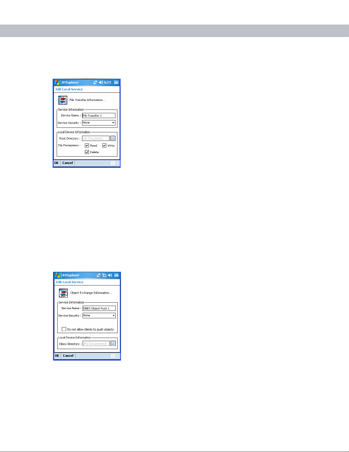
3 - 26 MC7090CN User Guide
File Transfer Service
File transfer allows other Bluetooth devices to browse files.
Figure 3-37
Service Name Displays the name of the service.
Service Security Select the type of security from the drop-down list. Options are None,
Root Directory Select the directory that other Bluetooth devices can access.
File Permissions Select the file permissions for the selected directory. Check the
File Transfer Information Window
Authenticate, or Authenticate/Encrypt.
appropriate box to grant read access, write access, and delete access.
OBEX Object Push Service
OBEX Object Push allows other Bluetooth devices to push contacts, business cards, pictures, appointments,
and tasks to the EDA.
Figure 3-38
OBEX Exchange Information Window
Service Name Displays the name of the service.
Service Security Select the type of security from the drop-down list.
Options are None, Authenticate, or Authenticate/Encrypt.
Page 73

Using Bluetooth 3 - 27
Do not allow clients to push
objects
Inbox Directory Select a directory where another Bluetooth device can
Disables clients from pushing objects to the EDA.
store files.
Personal Area Networking Service
Personal Area Networking hosts a Personal Area Network which allows communication with other Bluetooth
devices.
Figure 3-39
Personal Area Networking Window
Service Name Displays the name of the service.
Service Security Select the type of security from the drop-down list. Options are None,
Authenticate, or Authenticate/Encrypt.
Support Group Ad-Hoc
Networking
Select to enable Ad-Hoc networking.
Serial Port Service
Serial port allows other Bluetooth devices to access COM ports.
Figure 3-40
Serial Port Service Window
Page 74

3 - 28 MC7090CN User Guide
Service Name Displays the name of the service.
Service Security Select the type of security from the drop-down list. Options are None,
Local COM Port Select the COM port.
Local Baud Rate Select the communication baud rate.
Local Port Options Select the port option.
Security Tab
To adjust the security settings for an individual service, select the Services tab first, then select the individual
service, then Properties.
Authenticate, or Authenticate/Encrypt.
Figure 3-41
Use PIN Code (Incoming
Connection)
PIN Code Enter the PIN code.
Encrypt Link On All Outgoing
Connections
BTExplorer Settings - Security Tab
Select for automatic use of the PIN code entered in the PIN Code
text box. It is recommended not to use this automatic PIN code
feature. See Security on page 3-2 for more information.
Select to enable or disable encryption. Use encryption whenever
possible.
Page 75

Discovery Tab
Use the Discovery tab to set and modify discovered devices.
Using Bluetooth 3 - 29
Figure 3-42
Inquiry Length Sets the amount of time the EDA takes to discover Bluetooth devices
Name Discovery Mode Select either Automatic or Manual.
Discovered Devices Deletes all discovered devices and link keys.
BTExplorer Settings - Discovery Tab
in the area.
Virtual COM Port Tab
Use the Virtual COM Port tab to select the COM ports for Bluetooth communication.
Figure 3-43
COM4:Bluetooth Enable or disable COM Port 4.
COM5:Bluetooth Enable or disable COM Port 5
COM9:Bluetooth Enable or disable COM Port 9
BTExplorer Settings - Virtual COM Port Tab
Page 76

3 - 30 MC7090CN User Guide
Miscellaneous Tab
Figure 3-44
Highlight Connections Select the connection type to highlight when connected. In the
Apply Text Style Select the text style to apply to the connection text.
Apply Text Color Select the text color to apply to the connection text.
BTExplorer Settings - Miscellaneous Tab
Wizard Mode, the only options are Favorites or None. In the Explorer
Mode the options are None, Tree View Only, List View Only, or Tree
and List View.
Page 77

Chapter 4 Accessories
Introduction
MC7090CN accessories, listed below, provide a variety of product support capabilities.
Cables
Snap one of the following cables on to the EDA to connect an external device.
•
USB Client charge cable
•
RS232 charge cable
•
DEX cable
•
Modem inverter
Chapter 4
Accessories
•
Autocharge cable.
Cradles
•
Single Slot USB/Serial cradle charges the EDA main battery and a spare battery. It also synchronizes the
EDA with a host computer through a USB connection.
•
Four Slot Ethernet cradle charges the EDA main battery and connects the EDA with an Ethernet
network.
•
Vehicle cradle charges the EDA main battery and a spare battery.
Miscellaneous
•
Four Slot Spare Battery Charger charges up to four EDA spare batteries.
•
Multimedia Card or Secure Digital (SD) Card provides secondary non-volatile storage.
•
Belt Mounted Rigid Holster holds the EDA when not in use.
Snap-on Modules
•
MSR snaps on to the EDA and adds magstripe read capabilities.
•
TRG7000 Trigger Handle adds a gun-style handle with a scanning trigger to the EDA.
Page 78

4 - 2 MC7090CN User Guide
!
Multi Media Card (MMC) / Secure Digital (SD) Card
The MMC/SD card slot provides secondary non-volatile storage. The slot is located on the side of the EDA
(see Figure 4-1). Refer to the documentation provided with the card for more information, and follow the
manufacturer’s recommendations for use.
NOTE SD cards are interoperable with MMC cards; both can be used in MC7090CN EDAs.
CAUTION Follow proper ESD precautions to avoid damaging the MMC/SD. Proper ESD precautions
include, but are not limited to, working on an ESD mat and ensuring that the operator is properly
grounded.
To insert the MMC/SD card:
1. Power off the EDA.
2. Remove the card cover on the side of the EDA by loosening the screws and lifting the cover out of the slot.
Figure 4-1
3. Insert the card with the card contacts facing down and the cut corner on the right, until you feel a click.
4. Replace the housing cover and secure with the screws.
Card Cover Removal
To remove an MMC/SD card:
1. Power off the EDA.
2. Remove the card cover at the top of the EDA by loosening the screws and lifting the cover out of the slot.
3. Using the stylus, press and release the card to eject it.
4. Remove the card from the card slot.
5. Replace the card cover.
Page 79

Single Slot USB/Serial Cradle
Charge Status LED
This section describes how to use a Single Slot USB/Serial cradle with the EDA. For USB communication
setup procedures refer to the MC7090CN Integrator Guide.
The Single Slot USB/Serial Cradle:
•
Provides 5.4 VDC power for operating the EDA.
•
Synchronizes information between the EDA and a host computer. Refer to the MC7090CN Integrator
Guide for information on setting up a partnership between the EDA and a host computer.
•
Charges the EDA’s battery.
•
Charges a spare battery.
NOTE Use only an approved power supply output rated 12 Vdc and minimum 3.33A. The power
supply is certified to EN60950 with SELV outputs. Use of an alternative power supply will invalidate
any approval given to this device and may be dangerous.
HINWEIS Benutzen Sie nur eine von genehmigte Stromversorgung mit einer Ausgangsleistung
von 12 V (Gleichstrom) und mindestens 3.33A. Die Stromversorgung ist nach EN60950 für die
Verwendung in SELV-Stromkreisen zertifiziert. Bei Verwendung eines anderen Netzteils werden
alle für das Gerät gewährten Genehmigungen außer Kraft gesetzt, und der Betrieb kann gefährlich
sein.
Accessories 4 - 3
Charging the EDA Battery
Connect the cradle to power. Insert the EDA into the EDA slot to begin charging.
Figure 4-2
EDA Battery Charging
Page 80

4 - 4 MC7090CN User Guide
Spare Battery
Spare Battery
Charging LED
Charging the Spare Battery
Figure 4-3
Spare Battery Charging
Battery Charging Indicators
The Single Slot USB/Serial Cradle charges the EDA’s main battery and a spare battery simultaneously.
The EDA’s charge LED indicates the status of the battery charging in the EDA. See Table 1-2 on page 1-7 for
charging status indications.
The spare battery charging LED on the cradle indicates the status of the spare battery charging in the cradle.
See Table 4-1 for charging status indications.
The standard battery fully charges in approximately four hours and the extended capacity battery fully charges
in approximately eight hours.
Charging Temperature
Charge batteries in temperatures from 0oC to 40oC (32°F to 104°F). Note that at temperatures above 35oC,
charging is intelligently controlled by the EDA and the charging accessory in order to ensure safe operation
and optimize long-term battery life.
To accomplish this, for small periods of time, the EDA or accessory alternately enables and disables battery
charging to keep the battery at acceptable temperatures. The EDA or accessory indicates when charging is
disabled due to abnormal temperatures via its LED. See Table 1-2 on page 1-7 and Table 4-1.
Table 4-1
Spare Battery LED Charging Indicators
Spare Battery LED
(on cradle)
Indication
Off Battery is not charging; battery is not inserted correctly in the
cradle; cradle is not powered
Slow Blinking Amber Spare battery is charging.
Solid Amber Charging complete.
Fast Blinking Amber Charging error.
Page 81

Four Slot Ethernet Cradle
This section describes how to set up and use a Four Slot Ethernet cradle with the EDA. For cradle
communication setup procedures refer to the MC7090CN Integrator Guide.
The Four Slot Ethernet cradle:
•
Provides 5.4 VDC power for operating the EDA.
•
Connects the EDA (up to four) to an Ethernet network.
•
Simultaneously charges up to four EDAs.
NOTE Use only an approved power supply output rated 12 Vdc and minimum 9A. The power
supply is certified to EN60950 with SELV outputs. Use of an alternative power supply will invalidate
any approval given to this device and may be dangerous.
HINWEIS Benutzen Sie nur eine von genehmigte Stromversorgung mit einer Ausgangsleistung
von 12 V (Gleichstrom) und mindestens 9A. Die Stromversorgung ist nach EN60950 für die
Verwendung in SELV-Stromkreisen zertifiziert. Bei Verwendung eines anderen Netzteils werden
alle für das Gerät gewährten Genehmigungen außer Kraft gesetzt, und der Betrieb kann gefährlich
sein.
Accessories 4 - 5
Charging
Insert the EDA into a slot to begin charging.
Figure 4-4
EDA Battery Charging
Battery Charging Indicators
The EDA’s charge LED shows the status of the battery charging in the EDA. See Table 1-2 on page 1-7 for
charging status indications.
The standard battery fully charges in approximately four hours and the extended capacity battery fully charges
in approximately eight hours.
Page 82

4 - 6 MC7090CN User Guide
Release Lever
Charging Temperature
Charge batteries in temperatures from 0oC to 40oC (32°F to 104°F). Note that at temperatures above 35oC,
charging is intelligently controlled by the EDA and the charging accessory in order to ensure safe operation
and optimize long-term battery life.
To accomplish this, for small periods of time, the EDA or accessory alternately enables and disables battery
charging to keep the battery at acceptable temperatures. The EDA or accessory indicates when charging is
disabled due to abnormal temperatures via its LED. See Table 1-2 on page 1-7.
VCD7000 Vehicle Cradle
This section describes how to use a VCD7000 vehicle cradle with the EDA. For cradle installation and
communication setup procedures refer to the MC7090CN Integrator Guide.
Once installed in a vehicle, the cradle:
•
holds the EDA securely in place
•
provides power for operating the EDA
•
provides a serial port for data communication between an EDA and an external device (e.g., a printer)
•
re-charges the battery in the EDA
•
re-charges a standard capacity or extended capacity spare battery.
Charging the EDA Battery
Insert the EDA into the vehicle cradle to begin charging. A click indicates that the EDA button release locking
mechanism is enabled and the EDA is locked in place.
Figure 4-5
EDA Battery Charging
CAUTION Ensure the EDA is fully inserted in the cradle. Lack of proper insertion may result in
property damage or personal injury. Zebra is not responsible for any loss resulting from the use of
the products while driving.
Page 83

Accessories 4 - 7
Release Lever
Extended Capacity
Battery Shown
Battery Release Lever
Removing the EDA
To remove the EDA, hold back the release lever on the cradle and pull the EDA up and out of the cradle.
Figure 4-6
Removing the EDA
Charging the Spare Battery
Insert a spare battery to begin charging:
1. Lift the battery release lever.
Figure 4-7
2. Insert the spare battery in the spare battery charging slot in the cradle with the charging contacts facing up
and to the rear of the cradle.
3. Release the battery release lever. The battery release lever locks the spare battery into place.
Inserting the Spare Battery
Page 84

4 - 8 MC7090CN User Guide
Battery Release Lever
Extended Capacity
Battery Shown
To remove a spare battery, hold back the battery release lever and lift the battery from the spare battery slot.
Figure 4-8
Removing the Spare Battery
Battery Charging Indicators
The Vehicle Cradle charges the EDA’s main battery and a spare battery simultaneously.
The EDA’s charge LED indicates the status of the battery charging in the EDA. See Table 1-2 on page 1-7 for
charging status indications.
The spare battery charging LED on the cradle indicates the status of the spare battery charging in the cradle.
See Table 4-2 for charging status indications.
The standard battery fully charges in approximately four hours and the extended capacity battery fully charges
in approximately eight hours.
Charging Temperature
Charge batteries in temperatures from 0oC to 40oC (32°F to 104°F). Note that at temperatures above 35oC,
charging is intelligently controlled by the EDA and the charging accessory in order to ensure safe operation
and optimize long-term battery life.
To accomplish this, for small periods of time, the EDA or accessory alternately enables and disables battery
charging to keep the battery at acceptable temperatures. The EDA or accessory indicates when charging is
disabled due to abnormal temperatures via its LED. See Table 1-2 on page 1-7 and Table 4-2.
Table 4-2
Vehicle Cradle Spare Battery LED Charging Indicators
Spare Battery LED
(on cradle)
Indication
Off Battery is not charging; battery is not inserted correctly in the
cradle; cradle is not powered
Slow Blinking Amber Spare battery is charging.
Solid Amber Charging complete.
Fast Blinking Amber Charging error.
Page 85

Four Slot Spare Battery Charger
Shim
This section describes how to use the Four Slot Spare Battery Charger to charge up to four MC70 spare
batteries.
NOTE Use only an approved power supply output rated 12 Vdc and minimum 3.33A. The power
supply is certified to EN60950 with SELV outputs. Use of an alternative power supply will invalidate
any approval given to this device and may be dangerous.
HINWEIS Benutzen Sie nur eine von genehmigte Stromversorgung mit einer Ausgangsleistung
von 12 V (Gleichstrom) und mindestens 3.33A. Die Stromversorgung ist nach EN60950 für die
Verwendung in SELV-Stromkreisen zertifiziert. Bei Verwendung eines anderen Netzteils werden
alle für das Gerät gewährten Genehmigungen außer Kraft gesetzt, und der Betrieb kann gefährlich
sein.
MC70 Battery Shim Installation
Before charging a spare battery, snap the MC70 shim into the battery slot as shown in Figure 4-9.
Accessories 4 - 9
Figure 4-9
NOTE To purchase additional shims, contact your local account manager or Zebra Part number:
KT-76490-01.
MC70 Spare Battery Shim Installation
Page 86

4 - 10 MC7090CN User Guide
Spare Battery
Charging LEDs (4)
Spare Battery
Spare Battery Charging
1. Connect the charger to a power source.
2. Insert the spare battery into a spare battery charging well and gently press down on the battery to ensure
proper contact.
Battery Charging Indicators
Figure 4-10
The charger has an amber LED for each battery charging well. See Table 4-3 for charging status indications.
The standard battery fully charges in approximately 2.5 hours and the extended capacity battery fully charges
in approximately six hours.
Four Slot Spare Battery Charger
Charging Temperature
Charge batteries in temperatures from 0oC to 40oC (32°F to 104°F). Note that at temperatures above 35oC,
charging is intelligently controlled by the charger in order to ensure safe operation and optimize long-term
battery life.
To accomplish this, for small periods of time, the charger alternately enables and disables battery charging to
keep the battery at acceptable temperatures. The charger indicates when charging is disabled due to abnormal
temperatures via its LED. See Table 4-3.
Page 87

Accessories 4 - 11
Card Reader Slot
Table 4-3
Off No spare battery in slot; battery is not charging; battery is not inserted correctly
Slow Blinking Amber Spare battery is charging.
Solid Amber Charging complete.
Fast Blinking Amber Charging error.
Spare Battery LED Charging Indicators
LED Indication
in the charger; charger is not powered.
Magnetic Stripe Reader (MSR)
This section describes how to set up and use the snap-on MSR with the EDA. The MSR snaps on to the
bottom of the EDA and removes easily when not in use.
When attached to the EDA, the MSR allows the EDA to capture data from magnetic stripe cards. To download
MSR data capture software, visit http://www.zebra.com/support.
Attaching and Removing the MSR
To attach, slide the MSR onto the bottom of the EDA and secure by snapping the arms into the EDA housing.
Figure 4-11
To remove the MSR open the arms and pull the MSR from the EDA.
MSR Installation
NOTE When attaching a cable with a cup connector through the MSR to charge the device, you
cannot swipe cards.
Page 88

4 - 12 MC7090CN User Guide
Using the MSR
The MSR3000 sample application illustrates how an application handles MSR input (refer to Applications
User’s Guide).
To use the MSR:
1. Attach the MSR to the EDA.
2. Power on the EDA.
3. Install the MC70 Demo application onto the EDA. The demo is available with the SMDK. See the
MC7090CN Integrator Guide for more information.
4. Ta p Start - MC70 Demo - Test A pps - MSR MC70 or MSR Cameo to start the sample application.
5. Swipe the magnetic stripe card through the MSR, with the magnetic stripe on the card facing down. Swipe
the card in either direction, from left to right or from right to left. For best results, gently press down on the
card while swiping to ensure contact with the bottom of the reader.
Figure 4-12
Magnetic Stripe Card Swiping
TRG7000 Trigger Handle
The TRG7000 Trigger Handle pistol grip accessory adds a gun-style handle with a scanning trigger to the EDA.
It increases comfort when using the EDA in scan-intensive applications for extended periods of time. The
TRG7000 is intended for use with MC70 WLAN/PAN configurations.
Install the cleat onto the EDA before using the trigger handle. For cleat installation and communication setup
procedures refer to the MC7090CN Integrator Guide.
Page 89

Accessories 4 - 13
Release
Release
Inserting the EDA into the Trigger Handle
Slide the EDA into the Trigger Handle until it locks in place. The release secures the EDA to the Trigger
Handle.
Figure 4-13
Inserting the EDA into the Trigger Handle
Removing the EDA
To remove the EDA, press the release down and pull the EDA forward.
Figure 4-14
Removing the EDA
Scanning
To scan bar codes:
1. Start the EDA’s scanning application.
2. Aim the EDA at the bar code.
Page 90

4 - 14 MC7090CN User Guide
3. Pull the trigger on the handle. The Scan/Decode LED lights and a beep sounds to indicate a successful
decode.
Figure 4-15
Scanning with the Trigger Handle
Using a Cradle
CAUTION Do not place a Trigger Handle with an attachment, such as a Magnetic Stripe Reader
(MSR) into a cradle. Remove the attachment before inserting the Trigger Handle into the cradle.
To charge the EDA’s battery while the EDA is in the Trigger Handle, insert the EDA into either the Single-Slot
USB/Serial cradle or the Four-Slot Ethernet cradle.
Figure 4-16
Inserting the EDA Into the Cradle for Charging
Page 91

Cables
This section describes how to set up and use the cables. The cables are available with a variety of connection
capabilities.
The following communication/charge cables are available:
The following printer cables are available directly from the printer manufacturer:
•
Serial (RS232) Charge cable (9-pin D female with power input receptacle)
•
USB Client Charge cable (standard-A connector and a barrel receptacle for power)
•
Auto charge cable
•
DEX cable
•
Modem inverter cable.
•
O’Neil Printer cable
•
Zebra Printer cable.
Accessories 4 - 15
Figure 4-17
Cables
Communication/charge cables:
•
Provide the EDA with operating and charging power when used with the approved power supply.
•
Synchronize information between the EDA and a host computer. With customized or third party software,
it can also synchronize the EDA with corporate databases.
•
Provide serial connection through the serial pass-through port for communication with a serial device,
such as a host computer. For communication setup procedures, refer to the MC7090CN Integrator
Guide.
•
Provide USB connection through the USB pass-through port for communication with a USB device, such
as a host computer. For communication setup procedures, refer to the MC7090CN Integrator Guide.
Dedicated printer cables provide communication with a printer.
Page 92

4 - 16 MC7090CN User Guide
Battery Charging and Operating Power
The communication/charge cables can charge the EDA battery and supply operating power.
To charge the EDA battery:
1. Connect the communication/charge cable power input connector to the approved power source.
2. Slide the bottom of the EDA into the connector end of the communication/charge cable and gently press in
until it latches into the EDA. The EDA amber Charge LED indicates the EDA battery charging status. The
standard battery charges in less than four hours and the extended capacity battery charges in less than six
hours. See Table 1-2 on page 1-7 for charging status indications.
3. When charging is complete, remove the cable by gently pulling the EDA and the cable apart.
LED Charge Indications
The amber Charge LED on the EDA indicates battery charging status. See Table 1-2 on page 1-7 for charging
status indications.
Charging Temperature
Charge batteries in temperatures from 0oC to 40oC (32°F to 104°F). Note that at temperatures above 35oC,
charging is intelligently controlled by the EDA and the charging accessory in order to ensure safe operation
and optimize long-term battery life.
To accomplish this, for small periods of time, the EDA or accessory alternately enables and disables battery
charging to keep the battery at acceptable temperatures. The EDA or accessory indicates when charging is
disabled due to abnormal temperatures via its LED. See Table 1-2 on page 1-7.
Page 93

Chapter 5
Chapter 5 Maintenance & Troubleshooting
Introduction
This chapter includes instructions on cleaning and storing the EDA, and provides troubleshooting solutions for
potential problems during EDA operation.
Maintaining the EDA
For trouble-free service, observe the following tips when using the EDA:
•
Do not scratch the screen of the EDA. When working with the EDA, use the supplied stylus or
plastic-tipped pens intended for use with a touch-sensitive screen. Never use an actual pen or pencil or
other sharp object on the surface of the EDA screen.
Maintenance & Troubleshooting
Zebra recommends using a screen protector, p/n KT-67525-01.
•
The touch-sensitive screen of the EDA is glass. Do not to drop the EDA or subject it to strong impact.
•
Protect the EDA from temperature extremes. Do not leave it on the dashboard of a car on a hot day, and
keep it away from heat sources.
•
Do not store or use the EDA in any location that is dusty, damp, or wet.
•
Use a soft lens cloth to clean the EDA. If the surface of the EDA screen becomes soiled, clean it with a
soft cloth moistened with a diluted window-cleaning solution.
•
Periodically replace the rechargeable battery to ensure maximum battery life and product performance.
Battery life depends on individual usage patterns.
•
A screen protector is applied to the EDA. Zebra recommends using this to minimize wear and tear.
Screen protectors enhance the usability and durability of touch screen displays. Benefits include:
- Protection from scratches and gouges
- Durable writing and touch surface with tactile feel
- Abrasion and chemical resistance
- Glare reduction
- Keeping the device’s screen looking new
- Quick and easy installation.
Page 94

5 - 2 MC7090CN User Guide
Troubleshooting
EDA
Table 5-1
EDA does not turn on. Lithium-ion battery
Rechargeable
lithium-ion battery did
not charge.
Cannot see characters
on display.
During data
communication, no
data transmitted, or
transmitted data was
incomplete.
Troubleshooting the EDA
Problem Cause Solution
not charged.
Lithium-ion battery
not installed properly.
System crash. Perform a warm boot. If the EDA still does not turn on,
Battery failed. Replace battery. If the EDA still does not operate, perform
EDA removed from
cradle while battery
was charging.
EDA not powered on. Press the Power button.
EDA removed from
cradle or
disconnected from
host computer during
communication.
Charge or replace the lithium-ion battery in the EDA.
Install the battery properly. See Installing and Removing the
Main Battery on page 1-4.
perform a cold boot. See Resetting the EDA on page 2-20.
a warm boot, then a cold boot. See Resetting the EDA on
page 2-20.
Insert EDA in cradle. The standard capacity battery (1900
mAh) fully charges in less than four hours. The extended
capacity battery (3800 mAh) fully charges in less than eight
hours.
Replace the EDA in the cradle, or reattach the
communication cable and re-transmit.
Incorrect cable
configuration.
Communication
software was
incorrectly installed
or configured.
No sound. Volume setting is low
or turned off.
See the system administrator.
Perform setup. Refer to the MC70 Integrator Guide for
details.
Adjust the volume. See Speaker Icon on page 2-2.
Page 95

Maintenance & Troubleshooting 5 - 3
Table 5-1
EDA shuts off. EDA is inactive. The EDA turns off after a period of inactivity. If the EDA is
Tapping the window
buttons or icons does
not activate the
corresponding feature.
A message appears
stating that the EDA
memory is full.
Troubleshooting the EDA (Continued)
Problem Cause Solution
running on battery power, set this period from 1 to 5
minutes, in one-minute intervals. If the EDA is running on
external power, set this period to 1, 2, 5, 10, 15, or 30
minutes.
Check the Power window by selecting Start - Settings -
System tab and tapping the Power icon. Select the
Advanced tab and change the setting for a longer delay
before the automatic shutoff feature activates.
Battery is depleted. Replace the battery.
Battery is not
inserted properly.
Screen is not
calibrated correctly.
The system is not
responding.
Too many files stored
on the EDA.
Insert the battery properly. See Installing and Removing the
Main Battery on page 1-4.
Re-calibrate the screen. See Calibrating the Screen on
page 1-8.
Warm boot the system. See Resetting the EDA on page
2-20.
Delete unused memos and records. If necessary, save
these records on the host computer (or use an SD card for
additional memory).
EDA keeps powering
down to protect
memory contents.
Too many
applications installed
on the EDA.
The EDA’s battery is
low.
The radio is powered
on for a long time.
Remove user-installed applications on the EDA to recover
memory. Select Start - Settings - System tab and tap the
Remove Programs icon. Select the unused program and
tap Remove.
Recharge the battery.
Because this mode requires battery power, power it off
when not needed. Using the SetDeviceState() API (refer to
the SMDK Help File), set the Bluetooth to D4 power state.
Page 96

5 - 4 MC7090CN User Guide
Table 5-1
The EDA does not
accept scan input.
Troubleshooting the EDA (Continued)
Problem Cause Solution
Scanning application
is not loaded.
Unreadable bar
code.
Distance between
exit window and bar
code is incorrect.
EDA is not
programmed for the
bar code.
EDA is not
programmed to
generate a beep.
Battery is low. If the scanner stops emitting a laser beam upon a trigger
Load a scanning application on the EDA. See the system
administrator.
Ensure the symbol is not defaced.
Place the EDA within proper scanning range.
Program the EDA to accept the type of bar code being
scanned.
If the EDA does not beep on a good decode, set the
application to generate a beep on good decode.
press, check the battery level. When the battery is low, the
scanner shuts off before the EDA low battery condition
notification.
Note: If the scanner is still not reading symbols, contact the
distributor or Zebra.
Bluetooth Connection
Table 5-2
EDA cannot find
any Bluetooth
devices nearby.
When trying to
connect a Bluetooth
phone and EDA, the
phone thinks a
previously paired
EDA is used.
Troubleshooting Bluetooth Connection
Problem Cause Solution
Too far from other
Bluetooth devices.
The Bluetooth device(s)
nearby are not turned on.
The Bluetooth device(s)
are not in discoverable
mode.
The phone remembers
the name and address of
the EDA it last paired
with via the Bluetooth
radio.
Move closer to the other Bluetooth device(s), within a
range of 10 meters.
Turn on the Bluetooth device(s) to find.
Set the Bluetooth device(s) to discoverable mode. If
needed, refer to the device’s user documentation for help.
Manually delete the pairing device and name from the
phone. Refer to the phone’s user documentation for
instructions.
Page 97

Maintenance & Troubleshooting 5 - 5
Table 5-2
Can’t make my
Ericsson R520
phone
discoverable.
There is a delay in
the Bluetooth stack
re-initializing during
a resume from
suspend.
Piconet (the
connection between
a Bluetooth master
and one or more
Bluetooth slaves)
drops.
Troubleshooting Bluetooth Connection (Continued)
Problem Cause Solution
You attempted to bond
with the phone, and
when the phone
presented a “pairing
query,” you entered No.
This prevents the phone
from being discoverable
until it is reset.
This is normal behavior. No solution required.
The EDA suspends and
the Bluetooth radio
power turns off.
One of the devices are
out of range.
Reset the phone by removing its battery.
An application can register for notification of an EDA
resume by creating a message queue using the
CreateMsgQueue() API and power notifications using the
RequestPowerNotifications() API (refer to the SMDK Help
File). After an application receives a resume notification it
should close open Bluetooth sessions and reopen
them.This reestablishes the piconet lost during the
suspend.
My application
created a
successful
RFCOMM session
with another
Bluetooth device
but the session was
dropped.
After completing an
RFCOMM session
with another
Bluetooth device, I
was unable to
create a virtual
COM port to
connect to another
Bluetooth device.
Device went out of range
or was shut off.
The Microsoft Bluetooth
stack holds a baseband
connection for ten
seconds after an
application closes its
session and exits. This
was designed to allow for
speedy connections to
the same device if other
profiles were to connect.
Check the return value of APIs for errors. Look for a DCD
state change event in the Microsoft Bluetooth stack DCD
window of the Bluetooth connection.
Either wait 10 seconds, choose a different COM port
number for the virtual COM port, or modify
HKLM\software\Microsoft\bluetooth\l2cap\IdlePhys (which
defines the number of seconds to hold the connection).
Page 98

5 - 6 MC7090CN User Guide
Single Slot USB/Serial Cradle
Table 5-3
LEDs do not
light when EDA
Troubleshooting the Single Slot USB/Serial Cradle
Symptom Possible Cause Action
Cradle is not receiving
power.
Ensure the power cable is connected securely to both the cradle
and to AC power.
or spare
battery is
inserted.
EDA is not seated
firmly in the cradle.
Spare battery is not
seated firmly in the
Remove and re-insert the EDA into the cradle, ensuring it is firmly
seated.
Remove and re-insert the spare battery into the charging slot,
ensuring it is firmly seated.
cradle.
EDA battery is
not charging.
EDA was removed
from cradle or cradle
was unplugged from
AC power too soon.
Ensure cradle is receiving power. Ensure EDA is seated correctly.
Confirm main battery is charging under Start - Settings - System -
Power. The standard capacity battery (1900 mAh) fully charges in
less than four hours. The extended capacity battery (3800 mAh)
fully charges in less than eight hours.
Battery is faulty. Verify that other batteries charge properly. If so, replace the faulty
battery.
The EDA is not fully
seated in the cradle.
Ambient temperature
of the cradle is too
Remove and re-insert the EDA into the cradle, ensuring it is firmly
seated.
Move the cradle to an area where the ambient temperature is
between 0
o
C and 35oC.
warm.
Spare battery
is not charging.
During data
communication
, no data
transmits, or
transmitted
data was
incomplete.
Battery not fully seated
in charging slot.
Battery inserted
incorrectly.
Remove and re-insert the spare battery in the cradle, ensuring it
is firmly seated.
Re-insert the battery so the charging contacts on the battery align
with the contacts on the cradle.
Battery is faulty. Verify that other batteries charge properly. If so, replace the faulty
battery.
Ambient temperature
of the cradle is too
Move the cradle to an area where the ambient temperature is
between 0
o
C and 35oC.
warm.
EDA removed from
Replace EDA in cradle and retransmit.
cradle during
communications.
Incorrect cable
See the system administrator.
configuration.
Communication
Perform setup as described in the MC7090CN Integrator Guide.
software is not
installed or configured
properly.
Page 99

Four Slot Ethernet Cradle
Maintenance & Troubleshooting 5 - 7
Table 5-4
Attempt by the EDA
to ActiveSync failed.
Troubleshooting the Four Slot Ethernet Cradle
Symptom Cause Solution
EDA removed from
the cradle while the
LED was blinking
green.
Using an outdated
version of
ActiveSync.
ActiveSync on the
host computer has
not yet closed the
previous ActiveSync
session.
Incorrect cable
configuration.
Communication
software improperly
configured.
EDA ActiveSync
disabled or not
configured to accept
network connection.
Wait one minute and reinsert the EDA in the cradle. This
allows the cradle to attempt another synchronization.
Visit http://www.microsoft.com for the latest ActiveSync
software.
Wait one minute and reinsert the EDA in the cradle. This
allows the cradle to attempt another synchronization.
Ensure the correct cable (Ethernet) is used with the cradle.
Perform setup as described in the MC70 Integrator Guide.
On the EDA, tap Start - ActiveSync - To ol s - Options - Options
button. Then, uncheck the Enable PC sync using this
connection: check box.
During
communication, no
data transmits, or
transmitted data was
incomplete.
Host ActiveSync
disabled or not
configured to accept
network connection.
EDA removed from
cradle during
communications.
EDA has no active
connection.
On the host computer, check File - Connection Settings - Allow
network (Ethernet) Server Connection with this desktop
computer.
Replace EDA in cradle and retransmit.
An icon is visible in the status bar if a connection is currently
active.
Page 100

5 - 8 MC7090CN User Guide
Table 5-4
Troubleshooting the Four Slot Ethernet Cradle (Continued)
Symptom Cause Solution
Battery is not
charging.
Vehicle Cradle
Table 5-5
Troubleshooting the Vehicle Cradle
Symptom Possible Cause Action
EDA removed from
the cradle too soon.
Replace the EDA in the cradle. The standard capacity battery
(1900 mAh) fully charges in less than four hours. The
extended capacity battery (3800 mAh) fully charges in less
than eight hours. Tap Start - Settings - System - Power to view
battery status.
Battery is faulty. Verify that other batteries charge properly. If so, replace the
faulty battery.
EDA is not inserted
correctly in the
cradle.
Ambient
temperature of the
Remove the EDA and reinsert it correctly. Verify charging is
active. Tap Start - Settings - System - Power to view battery
status.
Move the cradle to an area where the ambient temperature is
between 0
o
C and 35oC.
cradle is too warm.
EDA battery
charging LED does
not light up.
EDA battery is not
recharging.
No data transmitted,
or transmitted data
was incomplete.
Cradle is not receiving
power.
EDA was removed from
the cradle too soon.
Ensure the power input cable is securely connected to the
cradle’s power port.
Replace the EDA in the cradle. The standard capacity
battery (1900 mAh) fully charges in less than four hours.
The extended capacity battery (3800 mAh) fully charges in
less than eight hours.
Battery is faulty. Replace the battery.
EDA is not placed
correctly in the cradle.
Remove the EDA from the cradle, and re-insert correctly. If
the battery still does not charge, contact customer support.
The EDA battery charging LED slowly blinks amber when
the EDA is correctly inserted and charging.
Ambient temperature of
the cradle is too warm.
EDA removed from
Move to an area where the ambient temperature is between
o
0
C and 35oC.
Replace EDA in cradle and retransmit.
cradle during
communication.
No null modem cable
was used.
Incorrect cable
Some external devices require a null modem cable.
Retransmit using a null modem cable.
See the system administrator.
configuration.
Cable missing or
disconnected.
Re-connect cable.
 Loading...